EP0596788B1 - Osteosynthesis device for spinal consolidation - Google Patents
Osteosynthesis device for spinal consolidation Download PDFInfo
- Publication number
- EP0596788B1 EP0596788B1 EP93402676A EP93402676A EP0596788B1 EP 0596788 B1 EP0596788 B1 EP 0596788B1 EP 93402676 A EP93402676 A EP 93402676A EP 93402676 A EP93402676 A EP 93402676A EP 0596788 B1 EP0596788 B1 EP 0596788B1
- Authority
- EP
- European Patent Office
- Prior art keywords
- rod
- rods
- bore
- threaded
- nut
- Prior art date
- Legal status (The legal status is an assumption and is not a legal conclusion. Google has not performed a legal analysis and makes no representation as to the accuracy of the status listed.)
- Expired - Lifetime
Links
Images


Classifications
-
- A—HUMAN NECESSITIES
- A61—MEDICAL OR VETERINARY SCIENCE; HYGIENE
- A61B—DIAGNOSIS; SURGERY; IDENTIFICATION
- A61B17/00—Surgical instruments, devices or methods, e.g. tourniquets
- A61B17/56—Surgical instruments or methods for treatment of bones or joints; Devices specially adapted therefor
- A61B17/58—Surgical instruments or methods for treatment of bones or joints; Devices specially adapted therefor for osteosynthesis, e.g. bone plates, screws, setting implements or the like
- A61B17/88—Osteosynthesis instruments; Methods or means for implanting or extracting internal or external fixation devices
-
- A—HUMAN NECESSITIES
- A61—MEDICAL OR VETERINARY SCIENCE; HYGIENE
- A61B—DIAGNOSIS; SURGERY; IDENTIFICATION
- A61B17/00—Surgical instruments, devices or methods, e.g. tourniquets
- A61B17/56—Surgical instruments or methods for treatment of bones or joints; Devices specially adapted therefor
- A61B17/58—Surgical instruments or methods for treatment of bones or joints; Devices specially adapted therefor for osteosynthesis, e.g. bone plates, screws, setting implements or the like
- A61B17/68—Internal fixation devices, including fasteners and spinal fixators, even if a part thereof projects from the skin
- A61B17/70—Spinal positioners or stabilisers ; Bone stabilisers comprising fluid filler in an implant
- A61B17/7049—Connectors, not bearing on the vertebrae, for linking longitudinal elements together
-
- A—HUMAN NECESSITIES
- A61—MEDICAL OR VETERINARY SCIENCE; HYGIENE
- A61B—DIAGNOSIS; SURGERY; IDENTIFICATION
- A61B17/00—Surgical instruments, devices or methods, e.g. tourniquets
- A61B17/56—Surgical instruments or methods for treatment of bones or joints; Devices specially adapted therefor
- A61B17/58—Surgical instruments or methods for treatment of bones or joints; Devices specially adapted therefor for osteosynthesis, e.g. bone plates, screws, setting implements or the like
- A61B17/68—Internal fixation devices, including fasteners and spinal fixators, even if a part thereof projects from the skin
- A61B17/70—Spinal positioners or stabilisers ; Bone stabilisers comprising fluid filler in an implant
- A61B17/7001—Screws or hooks combined with longitudinal elements which do not contact vertebrae
- A61B17/7041—Screws or hooks combined with longitudinal elements which do not contact vertebrae with single longitudinal rod offset laterally from single row of screws or hooks
-
- A—HUMAN NECESSITIES
- A61—MEDICAL OR VETERINARY SCIENCE; HYGIENE
- A61B—DIAGNOSIS; SURGERY; IDENTIFICATION
- A61B17/00—Surgical instruments, devices or methods, e.g. tourniquets
- A61B17/56—Surgical instruments or methods for treatment of bones or joints; Devices specially adapted therefor
- A61B17/58—Surgical instruments or methods for treatment of bones or joints; Devices specially adapted therefor for osteosynthesis, e.g. bone plates, screws, setting implements or the like
- A61B17/68—Internal fixation devices, including fasteners and spinal fixators, even if a part thereof projects from the skin
- A61B17/84—Fasteners therefor or fasteners being internal fixation devices
- A61B17/86—Pins or screws or threaded wires; nuts therefor
- A61B17/8605—Heads, i.e. proximal ends projecting from bone
-
- A—HUMAN NECESSITIES
- A61—MEDICAL OR VETERINARY SCIENCE; HYGIENE
- A61B—DIAGNOSIS; SURGERY; IDENTIFICATION
- A61B17/00—Surgical instruments, devices or methods, e.g. tourniquets
- A61B17/56—Surgical instruments or methods for treatment of bones or joints; Devices specially adapted therefor
- A61B17/58—Surgical instruments or methods for treatment of bones or joints; Devices specially adapted therefor for osteosynthesis, e.g. bone plates, screws, setting implements or the like
- A61B17/68—Internal fixation devices, including fasteners and spinal fixators, even if a part thereof projects from the skin
- A61B17/84—Fasteners therefor or fasteners being internal fixation devices
- A61B17/86—Pins or screws or threaded wires; nuts therefor
- A61B17/8625—Shanks, i.e. parts contacting bone tissue
- A61B17/863—Shanks, i.e. parts contacting bone tissue with thread interrupted or changing its form along shank, other than constant taper
-
- Y—GENERAL TAGGING OF NEW TECHNOLOGICAL DEVELOPMENTS; GENERAL TAGGING OF CROSS-SECTIONAL TECHNOLOGIES SPANNING OVER SEVERAL SECTIONS OF THE IPC; TECHNICAL SUBJECTS COVERED BY FORMER USPC CROSS-REFERENCE ART COLLECTIONS [XRACs] AND DIGESTS
- Y10—TECHNICAL SUBJECTS COVERED BY FORMER USPC
- Y10T—TECHNICAL SUBJECTS COVERED BY FORMER US CLASSIFICATION
- Y10T403/00—Joints and connections
- Y10T403/55—Member ends joined by inserted section
- Y10T403/553—Laterally inserted section
-
- Y—GENERAL TAGGING OF NEW TECHNOLOGICAL DEVELOPMENTS; GENERAL TAGGING OF CROSS-SECTIONAL TECHNOLOGIES SPANNING OVER SEVERAL SECTIONS OF THE IPC; TECHNICAL SUBJECTS COVERED BY FORMER USPC CROSS-REFERENCE ART COLLECTIONS [XRACs] AND DIGESTS
- Y10—TECHNICAL SUBJECTS COVERED BY FORMER USPC
- Y10T—TECHNICAL SUBJECTS COVERED BY FORMER US CLASSIFICATION
- Y10T403/00—Joints and connections
- Y10T403/71—Rod side to plate or side
- Y10T403/7182—Yoke or ring-type connector
- Y10T403/7188—Rod received in open channel
-
- Y—GENERAL TAGGING OF NEW TECHNOLOGICAL DEVELOPMENTS; GENERAL TAGGING OF CROSS-SECTIONAL TECHNOLOGIES SPANNING OVER SEVERAL SECTIONS OF THE IPC; TECHNICAL SUBJECTS COVERED BY FORMER USPC CROSS-REFERENCE ART COLLECTIONS [XRACs] AND DIGESTS
- Y10—TECHNICAL SUBJECTS COVERED BY FORMER USPC
- Y10T—TECHNICAL SUBJECTS COVERED BY FORMER US CLASSIFICATION
- Y10T403/00—Joints and connections
- Y10T403/71—Rod side to plate or side
- Y10T403/7194—Crossed rods
Definitions
- the present invention relates to an osteosynthesis device comprising a rod, and an element having a threaded section extending from a head and provided with a nut.
- Such a known osteosynthesis device for stabilizing and correcting the spine is provided with at least two screws, as an element with a threaded section.
- each of the screws includes a partially or completely threaded part to be implanted most often in the pedicle of a vertebra.
- the consolidation rod extends along the spinous process of the spine and must be quickly connected to the threaded sections of several pedicle screws, while ensuring precise positioning of the screws relative to each other and above all a connection effective removable between screws and rod.
- the rod is connected to a screw by tightening the rod between two suitable nuts screwed onto the threaded section of screw and laterally to the latter.
- a portion of the rod is wedged between a washer having an edge in the form of a half-gutter and a chamfered edge of the nut; the nut pushes the rod on the washer and the washer against the screw head which separates the threaded section and the part of the implanted screw.
- EP-A-0 408 489 describes an osteosynthesis device which overcomes the above drawbacks by means of a connecting clip, comprising a rod with threads on the right and on the left, an element having a threaded section extending from a intermediate head and fitted with a nut, and a connecting clip.
- the fastener comprises a first bore through which said rod passes, a slot opening axially into the first bore, and a second bore substantially perpendicular to the first slot and traversed by a part of said threaded section located between the head and the nut.
- the consolidation rod is threaded to be screwed into the first bore which is tapped.
- This thread connection requires the surgeon to turn the rod to adjust the positions of several fasteners on the rod depending on the position of the pedicle screws and above all does not allow other fasteners to be positioned opposite the screw when a fastener is tightened on the rod by the corresponding nut.
- said element according to EP-A-0 408 489 is an anchoring screw, the convex intermediate head of which encloses, with the nut also having a convex contact surface, the branches of the fastener shared by the slot.
- the anchor screws being already installed, the second bores of the fasteners already screwed on the consolidation rod must be previously oriented and positioned respectively opposite the threaded sections of the implanted screws. This prepositioning is very difficult to perform.
- this prepositioning in combination with the screwing of the rod into the fasteners does not allow the surgeon to adjust the distances and relative positions of the fasteners between them and consequently the traction / pushing forces on the sections of the consolidation rod between the ties.
- the present invention aims to improve the convenience and speed of assembly, while ensuring easy adjustment of the distances and relative positions of the fasteners on the consolidation rod.
- an osteosynthesis device according to the invention is as defined in claim 1.
- the connecting fastener partially housed between the nut and the screw head offers a bearing surface on the periphery of the rod incomparably higher than the known nuts or the known combination of the nut and the half-gutter washer. Thanks to pinching, the fastener can almost completely enclose a section of the rod and therefore adhere to almost the entire periphery of the section of the rod.
- the assembly is particularly rigid, in particular against any attempt to rotate the rod around its axis.
- the smooth nature of the first bore allows any loose fastener to slip independently of other fasteners.
- the nut tightening the branches of the fastener separated by the slot is used naturally so that the nut is not stressed by forces close to radial directions.
- the second slot can be substantially perpendicular or parallel to the first bore, in order to facilitate the introduction of the fastener between the nut and the head of a screw, particularly when the consolidation rod connects numerous screws and other elements with threaded section. .
- the cylindrical skirt of the nut has a diameter which is substantially equal to the diameter of the second bore and greater than the width of the second slot.
- the second slot narrower than the diameter of the skirt and of the second bore maintains the threaded section of the screw in the connecting clip when the nut is screwed onto the threaded section and narrows the first slot.
- an element with a threaded section can comprise a part in the shape of a claw separated from said threaded section by the head.
- the device may comprise a means having a bore traversed by sliding by the rod and having a portion in the shape of a claw, and a means of pressure radial to the rod to keep immobile said means mounted to slide on the rod.
- claw-shaped sliding elements and means are intended to cling to the vertebral processes.
- the invention also relates to the transverse stabilization between two consolidation rods side by side, for example arranged to the right and to the left of the spinous process, and the longitudinal stabilization between two rods along the same side of the spinous process.
- An osteosynthesis device comprises at least one basic assembly for connecting a consolidation rod 1 to an element with a threaded section, which is constituted by a pedicle screw 2 according to FIG. 1, by means of a quick connection means 3.
- a consolidation rod 1 to an element with a threaded section, which is constituted by a pedicle screw 2 according to FIG. 1, by means of a quick connection means 3.
- the pedicle screw 2 is in the form of a stud and is composed of a partially threaded part 20-21 substantially frustoconical, a cylindrical section 22 threaded substantially over its entire length, and an intermediate gripping head 23, here in section hexagonal, located between the threaded part and section.
- the part 20-21 comprises, substantially over half of its length, a substantially frustoconical section 20 having a relatively wide round thread pitch, terminated by a self-tapping end with a foam tip 201, that is to say a point comprising two Opposite axial grooves with a v-shaped section, so as to easily penetrate and be firmly anchored in the cancellous bone of a vertebral body.
- a tapered section 21 arranged between the section 20 and the head 23 completes the part of the screw 20-21.
- the section 21 is covered with a rough coating of pure porous titanium so that its micro-crevices are filled by bone growth of the vertebral pedicle where it is implanted.
- This anchoring of the rough section 21 in the pedicle provides primary stability to the device, unlike a fibrous connection with a smooth section of known screw made of Nickel-Chromium or Cobalt-Chromium alloy crossing the pedicle.
- the gripping head 23 is intended to be taken by a corresponding operating key to screw the threaded section 20 into the pedicle and vertebral body until the head 23 abuts against the cortical bone.
- the second threaded section 22 constitutes the posterior extra-vertebral end of the screw 2 after implantation, and is intended to cooperate with the connecting means 3 and to receive a nut 24.
- this threaded section posterior 22 is designed initially relatively long so as to adapt its length by preoperative sawing.
- the end face of the threaded section 22 includes a slot 221 for receiving a screwdriver, as illustrated in FIG. 1, or else a polygonal end, for example hexagonal, for cooperating with an operating key so as to prevent possible rotation of the screw 2 when the connecting means 3 are tightened by the nut 24, as will be seen later.
- a quick connection means is a fastener 3 which is substantially in the form of a small block which is divided into two anterior and posterior faces symmetrical with respect to a slot 35.
- the first halves, here beveled trapezoidally, of the anterior and posterior faces of the attachment 3, substantially “vertical" after implantation of the device, are pierced in parallel in a smooth bore 30 slidingly receiving the rod 1.
- Second halves of the two anterior and posterior faces of the fastener 3 are pierced perpendicularly by a second smooth bore 31 which is perpendicular to the first bore 30 and not concurrent with the latter.
- the bore 31 has a section contained in the polygonal sections of the head 242 of the nut 24 and of the head 23 of the screw 2.
- the threaded section 22 of a screw 2 in particular is freely received in the bore 31.
- the ends of the first bore 30 have countersinks 32 facilitating the penetration of the rod 1 into the bore 30.
- On the rear face of the fastener 3 is provided a small tapped hole 33 opening radially into the first smooth bore 30 so that a small hexagon socket headless pressure screw 34 screwed into the hole 33 keeps the fastener 3 stationary on the rod 1 in a desired temporary position.
- the fastener 3 also comprises two rectangular slots 35 and 36 which extend substantially perpendicular to each other from a "lateral" face of the fastener which is parallel to the bore 30 and opposite to the 'bore 30 relative to bore 31 and which is oriented substantially to the left or right after implantation of the device ( Figure 6).
- the first slot 35 is formed along a substantially median plane of the coplanar attachment to the axis of the bore 30.
- the slot 35 is traversed perpendicularly by the bore 31, opens axially into the bore 30, and has a width very much less than the diameter of the rod 1 and the bore 30.
- the second slot 36 opens axially into the second bore 31, is substantially perpendicular to the first bore 30, and offers a width greater than the diameter of the threaded section of screws 22 and less than the diameter of the bore 31.
- the second bore 31 receives a complementary cylindrical skirt with a chamfered end 241 which is disposed under the polygonal head 242 of the nut 24.
- the skirt 241 is shorter than the bore 31 and has a diameter substantially equal to the diameter of the bore 31 and greater than the width of the slot 36 so that the skirt does not escape from the fastener after tightening the nut 24.
- the embodiment illustrated in Figure 1 advantageously avoids lateral sliding of the fastener 3 relative to the screw 2 during the assembly of the latter, thanks to the imprisonment of the skirt 241 in the bore 31 which is wider that the slot 36, although the threaded section 22 passes through the slot 35 during assembly of the device.
- the fastener 3 constitutes a collar tightening the rod 1 and connecting the rod 1 to the screw 2.
- the rod slides in the bore 30 during the assembly and positioning of different parts of the osteosynthesis device and after implantation of the screw 2.
- the front and rear faces of the fastener 3 are clamped between the screw head 23 and the nut head 242 so as to substantially bend said faces towards each other and shrink the first slot 35 to pinch the rod 1, and simultaneously quickly and securely link the screw 1 to the fastener 3 and therefore to the rod 1. Thanks to the small width of the first slot 35 of the fastener 3, almost all of the circular periphery of the section of the rod 1 contained in the bore 30 is pinched in the first bore 30 which , initially split, closes and bends the rod 1.
- a loosening of the pinching of the rod 1 by the bore 30 to modify the relative positions of the screw 2 and the rod 1 is obtained by loosely loosening the nut 24, while still maintaining the skirt 241 in the bore 31 so that the threaded section 22 does not escape through the slot 36.
- a connecting clip 3a has, in a manner analogous to the clip 3 in FIG. 2, a first smooth bore 30a into which opens a first slot 35a axial to this bore, a second smooth bore 31a perpendicular to the bore 30a, and a small tapped hole 33a for clamping screw 34a, radial to the bore 30.
- a second slot 36a which, like the slot 36 in the first fastener 3, opens axially into the second bore 31 and is perpendicular to the first slot 35a, but which is formed laterally in an "upper” or “lower” face of the fastener 3a substantially parallel, not perpendicular, to the first bore 30a.
- the invention thus provides two types of attachment with lateral slit 36a, depending on whether the slit 36a is oriented “upwards”, or “downwards” towards the coccyx, as shown in FIG. 6.
- the small temporary clamping screws 34, 34a assist in maintaining the corresponding fasteners 3, 3a at desired positions along a common rod 1 when several fasteners 3, 3a mounted on the rod 1 are to be engaged by the slots 36, 36a and the bores 31, 31a simultaneously in threaded sections 22 of corresponding screws 2 (or threaded sections 41 of claws 4; FIG. 4).
- the assembly between a rod 1, an element with a threaded section such as a screw 2, and a fastener 3, 3a further comprises preferably a means traversed by the threaded section 22 of the screw 2 and disposed between the head of screw 23 and the nut head 242 for damping relative micro-displacements between the rod 1 and the screw 2.
- This means for damping thus contributes to cancel spinal micro-displacements from one vertebra to the other and therefore d '' a pedicle screw to the other and thus to avoid cracks or fractures of the screw 2 and / or of the rod 1.
- This means for damping comprises a washer 25 of damping material, such as elastomer or polyurethane or silicone, threaded onto the threaded section 22.
- this washer 25 is braced by two metal guide washers 26, which are preferably fused to the washer 25; this set of washers 25 + 26 is threaded around the section 22 and is enclosed at the base of the section 22, between the screw head 23 and the front face of the fastener 3, or 3a.
- this first assembly of washers can only comprise one washer 25 made of damping material and a single metal washer 26.
- a second assembly of washers comprising at least one washer made of damping material either replaces the first assembly of washers, either is combined with the latter, and is disposed between the rear face of the fastener 3, 3a and the head 242 of the nut 24.
- the element with a threaded section previously constituted by a screw 2 is here in the form of a first vertebral claw 4.
- This claw 4 also includes a cylindrical threaded section 41 intended to receive a nut 24 and to entering a second bore 31, 31a of attachment 3, 3a through the second slot 36, 36a of this attachment; by way of example, FIG. 4 shows a claw assembly 4 with a fastener 3a with a second lateral slot 36a.
- Underlying the threaded section 41 of the claw 4 is provided a portion in the form of a substantially circular half-crescent 42, forming a "claw", which is separated from the threaded section 41 by a rectangular head 43 and which is terminated by a substantially pointed end 44.
- the part 42 is intended to hang the edges of various recesses of the vertebrae, in particular pedicle, lumbar, thoracic, supraminar, sub-laminar, and transverse.
- the claw 4 can be approached substantially laterally, by the right or the left, or by the top or the bottom, by one of the three fasteners 3, 3a, and its part in the form of a semi-crescent 42 may be oriented in any direction by virtue of the rotation of the threaded section 41 in the bore 31, 31a of the clip 3, 3a.
- FIG. 5 A second claw 5 similar to the previous claw 4 is shown in FIG. 5.
- This second claw 5 comprises a half-crescent-shaped part 52 analogous to part 42, and a parallelepiped head 53 comprising a bore 55 which is mounted at sliding on a consolidation rod 1.
- the tip 54 of the claw is located in an axial plane to the bore 55; however, according to other embodiments, the half-crescent-shaped part 52 can be oriented in any way and as required around a median axis of the head 53 perpendicular to the bore 55. Along this median axis is formed by a tapped hole 51 starting from the often posterior face of the head 53 opposite the half-crescent-shaped part 52 and opening radially into the bore 55.
- a small pressure screw 56 without a six head hollow sides enters the hole 51 so as to block in translation and in rotation the rod 1 in the bore 55, and thus maintain the claw 5 on the rod 1.
- Such a second claw 5 mounted to slide on the rod 1 can be anchored for example in a transverse or thorny process of a vertebra.
- FIG. 6 schematically shows in latero-posterior view, by way of example, a rigid assembly of various parts which can enter into the constitution of an osteosynthesis device for spinal consolidation according to the invention.
- this device there are pedicle screws 2 with nut 24 and damping means 25 + 26 as well as first claws 4 with nut 24 which are connected to several rods 1, here three in number 1a, 1b and 1c, by l intermediary of corresponding fasteners 3 and 3a as well as a second vertebral claw 5 fixed around the rod 1c.
- the first and second rods 1a and 1b are two rods to be connected to sets of screws situated respectively to the right and to the left of the spinous process of the spine and are therefore arranged substantially side by side by means of at least one of two means transverse stabilization 6 and 7.
- the first and third rods 1a and 1c are arranged along the same side of the spinous process, for example the right side.
- the third rod 1c may be intended to extend a spinal consolidation already carried out by the means linked to the first rod 1a; a longitudinal stabilization means 8 is therefore provided between the ends of the rods 1a and 1c.
- the first transverse stabilization means 6 is shown in FIG. 7 and comprises an elongated substantially rectangular stabilization plate 60, first two rod hooks 61 as well as two nuts 62 and two notched washers 63.
- the plate 60 has a smooth front face 601 to be applied to the two rods 1a and 1b and a rear face 602 having small parallel notches capable of meshing with notched faces 632 of the two washers 63.
- Two oblong slots 603 are formed longitudinally in the plate 60 to be disposed substantially transversely to the rods 1a and 1b. According to another variant, the two lights are replaced by a longer light.
- the hooks 61 have a shape analogous to the first vertebral claws 4, such as that shown in FIG. 4, but have a size reduced substantially by half compared to the claws 4.
- a hook 61 comprises a threaded section 611 and a grip part shape of a circular semi-crescent 612 as well as a rectangular head 613 between the section 611 and the part 612.
- the length of the hook head 613 is substantially less than that of the slots 603 in the plate 60.
- the substantially semicircular concave surface 615 of the hook 61 has a diameter substantially greater than the diameter D1 rods 1a, 1b and has a lateral opening 614 whose parallel surfaces are substantially inclined relative to the axis of the threaded section 611 and towards the section 611, and therefore relative to the plate 60 after tightening.
- Two first hooks 61 are thus mounted on two rods 1a and 1b and connected by a common plate 60.
- the hooks can be arranged back-to-back between the rods 1a and 1b as shown in FIG. 7, or else face-to- facing the outside of the set of two rods, or alternatively in series and respectively outside and inside the set of two rods.
- the two rods 1a and 1b can be stabilized by two plates 60 and four hooks 61 by forming a non-deformable quadrilateral so as to consolidate the assembly of these parts in contraction or in relaxation, as shown in Figure 6.
- l spacing at the ends of the rods 1a and 1b can be increased or decreased, after loosening the nuts 62 of the stabilization plate 60 and disengagement of the notched washers 63 from the face of the plate 602, by moving away or bringing the rod hooks and corresponding notched washers 61 and 63 by sliding the hooks in the slots 603 of the plate 60.
- a second transverse stabilization means 7 comprises, with reference to FIG. 8, a thin bar 70 as well as two second rod hooks 71 each provided with a small pressure screw 72 without head and with hexagon socket.
- the bar 70 has a smooth cylindrical central part 701 separating two threaded end parts 702 which offer coplanar longitudinal flats 703 parallel to the axis of the bar 70.
- Each of the second rod hooks 71 has a shape analogous to a second vertebral claw 5, such as that shown in FIG. 5, but having a size reduced substantially by half.
- a hook 71 comprises a parallelepiped head 713 and a grip part substantially in the form of a circular semi-crescent 712 for hooking a rod 1a, 1b.
- the head 713 comprises an oblong half-tapped hole 717 which extends parallel to the hooked grip part 712 and perpendicular to the rod 1a, 1b hooked by the latter.
- a tapped hole 711 is made to receive a pressure screw 72 perpendicular both to the bar 70 and to the rod 1a, 1b after assembly.
- the hole 717 is divided, in cross section, into a first concave longitudinal portion at least partially tapped 718 and a second smooth concave longitudinal portion 719 by with respect to a plane parallel to the axis of hole 717 and perpendicular to hole 711.
- the oblong section of hole 718 is longer and at least substantially as wide as the diameter of the threaded parts of bar 702.
- the first portion 718 is preferably tapped at least at the bottom with a thread corresponding to the threaded parts 702 of the bar 70 and is arranged opposite the tapped hole 711 relative to the axis of the hole 717, towards the front part in the form of a semi-crescent 712.
- the second smooth portion 719 is disposed towards the rear face of the hole 717, and the tapped hole 711 opens transversely into this smooth portion.
- the second stabilization means 7 is mounted in the following manner.
- Each of the second hooks 71, the oblong half-tapped holes 717 of which have been released from the screws 72, are threaded onto the threaded end parts 702 of the bar 70 on either side of the two rods 1a and 1b and are arranged with their parts 712 in the form of a circular semi-crescent, for example facing one another as shown in FIG. 8.
- the threaded bar parts 702 are meshed in the tapped portions 718 of the holes 717.
- This assembly is very resistant against any separation or removal of the hooks 71 thanks to the relatively high number of threads cooperating between the hole portions 718 and the bar parts 702.
- this assembly is quick to assemble or disassemble, without requiring unscrewing. along the ends of bar 702, since these are placed in the oblong holes 718.
- the longitudinal stabilizing means is in the form of a connecting rod 8.
- the connector 8 has a parallelepipedal shape in which is formed a longitudinal hole 81 having an oblong cross section.
- the width of the orifice 81 and the diameter of the semicircular end walls 810 of the orifice 81 are substantially equal to the diameter D1 of the rods 1a, 1c.
- the rear face of the connector 8 is pierced with a tapped hole 82 opening transversely and centrally in the oblong orifice 81.
- the hole 82 is suitable for receiving a small needle screw 83 without a hexagon socket head having a smooth frustoconical pointed end 84.
- the height H8 (transverse length) of the orifice 81 is greater than the sum of the diameters of the rods 1a and 1c, but less than the sum of the diameters of the rods 1a and 1c and of the needle screw 83.
- the needle screw 83 is screwed into the orifice 82 so that its frustoconical pointed end 84 progressively spreads the rods 1a and 1c and wedges them firmly against the walls semicircular opposite 810 of the hole 81, which definitively and securely connects the two rods 1a and 1c.
- a connector has an orifice 81 having a higher height to connect there by wedging several rods side by side.
- said height H8 is greater than the sum of the diameters of three, respectively four consolidation rods and less than the sum of the diameters of the three respectively four rods and the diameters of two, respectively three needle screws screwed transversely in the fitting and each having a frustoconical end disposed between two respective rods.
Abstract
Description
La présente invention concerne un dispositif d'ostéosynthèse comprenant une tige, et un élément ayant un tronçon fileté s'étendant à partir d'une tête et muni d'un écrou.The present invention relates to an osteosynthesis device comprising a rod, and an element having a threaded section extending from a head and provided with a nut.
Un tel dispositif d'ostéosynthèse connu pour stabiliser et corriger le rachis est muni au moins de deux vis, en tant qu'élément à tronçon fileté. Outre le tronçon fileté servant à la relier à la tige de consolidation au moyen de l'écrou, chacune des vis comprend une partie partiellement ou complètement filetée à implanter le plus souvent dans le pédicule d'une vertèbre.Such a known osteosynthesis device for stabilizing and correcting the spine is provided with at least two screws, as an element with a threaded section. In addition to the threaded section used to connect it to the consolidation rod by means of the nut, each of the screws includes a partially or completely threaded part to be implanted most often in the pedicle of a vertebra.
La tige de consolidation s'étend le long de l'apophyse épineuse du rachis et doit être reliée rapidement aux tronçons filetés de plusieurs vis pédiculaires, tout en assurant un positionnement précis des vis l'une par rapport à l'autre et surtout une liaison démontable efficace entre les vis et la tige.The consolidation rod extends along the spinous process of the spine and must be quickly connected to the threaded sections of several pedicle screws, while ensuring precise positioning of the screws relative to each other and above all a connection effective removable between screws and rod.
Selon la technique antérieure, la tige est reliée à une vis en serrant la tige entre deux écrous adéquats vissés sur le tronçon fileté de vis et latéralement à ce dernier. Selon une autre variante connue, une portion de la tige est coincée entre une rondelle ayant une bordure en forme de demi-gouttière et une arête chanfreinée de l'écrou; l'écrou pousse la tige sur la rondelle et la rondelle contre la tête de vis qui sépare le tronçon fileté et la partie de vis implantée.According to the prior art, the rod is connected to a screw by tightening the rod between two suitable nuts screwed onto the threaded section of screw and laterally to the latter. According to another known variant, a portion of the rod is wedged between a washer having an edge in the form of a half-gutter and a chamfered edge of the nut; the nut pushes the rod on the washer and the washer against the screw head which separates the threaded section and the part of the implanted screw.
Ces liaisons connues entre vis et tige n'offrent pas de portée suffisante aux écrous, ou à la rondelle en demi-gouttière et l'écrou, sur la tige pour empêcher la rotation, voire la translation, de la tige. Le tronçon fileté et surtout les écrous subissent des efforts asymétriques par rapport à leur axe ce qui accroit le risque de rupture de ces pièces notamment lorsque la tige de consolidation est soumise à une flexion ou torsion du rachis.These known connections between screw and rod do not provide sufficient reach for the nuts, or the half-gutter washer and the nut, on the rod to prevent rotation, or even translation, of the rod. The threaded section and especially the nuts undergo asymmetrical forces with respect to their axis which increases the risk of rupture of these parts in particular when the consolidation rod is subjected to a bending or twisting of the spine.
La EP-A-0 408 489 décrit un dispositif d'ostéosynthèse remédiant aux inconvénients précédents grâce à une attache de liaison, comprenant une tige avec filetages à droite et à gauche, un élément ayant un tronçon fileté s'étendant à partir d'une tête intermédiaire et muni d'un écrou, et une attache de liaison. L'attache comprend un premier alésage traversé par ladite tige, une fente débouchant axialement dans le premier alésage, et un second alésage sensiblement perpendiculaire à la première fente et traversé par une partie dudit tronçon fileté localisée entre la tête et l'écrou.EP-A-0 408 489 describes an osteosynthesis device which overcomes the above drawbacks by means of a connecting clip, comprising a rod with threads on the right and on the left, an element having a threaded section extending from a intermediate head and fitted with a nut, and a connecting clip. The fastener comprises a first bore through which said rod passes, a slot opening axially into the first bore, and a second bore substantially perpendicular to the first slot and traversed by a part of said threaded section located between the head and the nut.
Selon cette demande de brevet, d'une part, la tige de consolidation est filetée pour être vissée dans le premier alésage qui est taraudé. Cette liaison par filetage oblige le chirurgien à tourner la tige pour ajuster les positions de plusieurs attaches sur la tige en fonction de la position des vis pédiculaires et surtout ne permet pas de positionner d'autres attaches en face de vis lorsqu'une attache est serrée sur la tige par l'écrou correspondant.According to this patent application, on the one hand, the consolidation rod is threaded to be screwed into the first bore which is tapped. This thread connection requires the surgeon to turn the rod to adjust the positions of several fasteners on the rod depending on the position of the pedicle screws and above all does not allow other fasteners to be positioned opposite the screw when a fastener is tightened on the rod by the corresponding nut.
D'autre part, ledit élément selon la EP-A-0 408 489 est une vis d'ancrage dont la tête intermédiaire bombée enserre, avec l'écrou ayant également une surface de contact bombée, les branches de l'attache partagées par la fente. Toutefois, lors de l'assemblage, les vis d'ancrage étant déjà implantées, les seconds alésages des attaches déjà vissées sur la tige de consolidation doivent être préalablement orientés et positionnés en regard respectivement des tronçons filetés des vis implantées. Ce prépositionnement est très difficile à effectuer. En outre ce prépositionnement en combinaison avec le vissage de la tige dans les attaches ne permet pas au chirurgien de régler les distances et positions relatives des attaches entr'elles et en conséquence les efforts de traction/poussée sur les tronçons de la tige de consolidation entre les attaches.On the other hand, said element according to EP-A-0 408 489 is an anchoring screw, the convex intermediate head of which encloses, with the nut also having a convex contact surface, the branches of the fastener shared by the slot. However, during assembly, the anchor screws being already installed, the second bores of the fasteners already screwed on the consolidation rod must be previously oriented and positioned respectively opposite the threaded sections of the implanted screws. This prepositioning is very difficult to perform. In addition, this prepositioning in combination with the screwing of the rod into the fasteners does not allow the surgeon to adjust the distances and relative positions of the fasteners between them and consequently the traction / pushing forces on the sections of the consolidation rod between the ties.
La présente invention vise à améliorer la commodité et la rapidité du montage, tout en garantissant un réglage aisé des distances et positions relatives des attaches sur la tige de consolidation.The present invention aims to improve the convenience and speed of assembly, while ensuring easy adjustment of the distances and relative positions of the fasteners on the consolidation rod.
A cette fin, un dispositif d'ostéosynthèse selon l'invention est tel que défini dans la revendication 1.To this end, an osteosynthesis device according to the invention is as defined in
L'attache de liaison logée partiellement entre l'écrou et la tête de vis offre une surface porteuse sur la périphérie de la tige incomparablement plus élevée que les écrous connus ou la combinaison connue de l'écrou et la rondelle à demi-gouttière. Grâce au pinçage, l'attache peut enserrer quasiment totalement un tronçon de la tige et donc adhérer à la quasi-totalité de la périphérie de la section de la tige. L'assemblage est particulièrement rigide notamment contre toute tentative de rotation de la tige autour de son axe.The connecting fastener partially housed between the nut and the screw head offers a bearing surface on the periphery of the rod incomparably higher than the known nuts or the known combination of the nut and the half-gutter washer. Thanks to pinching, the fastener can almost completely enclose a section of the rod and therefore adhere to almost the entire periphery of the section of the rod. The assembly is particularly rigid, in particular against any attempt to rotate the rod around its axis.
Le caractère lisse du premier alésage autorise un glissement de toute attache non serrée indépendamment d'autres attaches.The smooth nature of the first bore allows any loose fastener to slip independently of other fasteners.
Lorsque la première fente avant montage a une largeur relativement faible, l'écrou serrant les branches de l'attache séparées par la fente est utilisé naturellement de sorte que l'écrou ne soit pas sollicité par des efforts proches de directions radiales.When the first slot before mounting has a relatively small width, the nut tightening the branches of the fastener separated by the slot is used naturally so that the nut is not stressed by forces close to radial directions.
La seconde fente peut être sensiblement perpendiculaire ou parallèle au premier alésage, afin de faciliter l'introduction de l'attache entre l'écrou et la tête d'une vis particulièrement lorsque la tige de consolidation relie de nombreuses vis et autres éléments à tronçon fileté.The second slot can be substantially perpendicular or parallel to the first bore, in order to facilitate the introduction of the fastener between the nut and the head of a screw, particularly when the consolidation rod connects numerous screws and other elements with threaded section. .
Selon une autre variante de l'invention, la jupe cylindrique de l'écrou possède un diamètre qui est sensiblement égal au diamètre du second alésage et supérieur à la largeur de la seconde fente.According to another variant of the invention, the cylindrical skirt of the nut has a diameter which is substantially equal to the diameter of the second bore and greater than the width of the second slot.
La seconde fente plus étroite que le diamètre de la jupe et du second alésage maintient le tronçon fileté de la vis dans l'attache de liaison lorsque l'écrou est vissé sur le tronçon fileté et retrécit la première fente.The second slot narrower than the diameter of the skirt and of the second bore maintains the threaded section of the screw in the connecting clip when the nut is screwed onto the threaded section and narrows the first slot.
Selon une autre réalisation, un élément à tronçon fileté peut comporter une partie en forme de griffe séparée dudit tronçon fileté par la tête.According to another embodiment, an element with a threaded section can comprise a part in the shape of a claw separated from said threaded section by the head.
Le dispositif peut comprendre un moyen ayant un alésage traversé à coulissement par la tige et ayant une partie en forme de griffe, et un moyen de pression radial à la tige pour maintenir immobile ledit moyen monté à coulissement sur la tige. Ces éléments et moyens coulissants en forme de griffe sont destinés à s'accrocher à des apophyses vertébraux.The device may comprise a means having a bore traversed by sliding by the rod and having a portion in the shape of a claw, and a means of pressure radial to the rod to keep immobile said means mounted to slide on the rod. These claw-shaped sliding elements and means are intended to cling to the vertebral processes.
L'invention concerne également la stabilisation transversale entre deux tiges de consolidation côte à côté, par exemple disposées à droite et à gauche de l'apophyse épineuse, et la stabilisation longitudinale entre deux tiges le long du même côté de l'apophyse épineuse.The invention also relates to the transverse stabilization between two consolidation rods side by side, for example arranged to the right and to the left of the spinous process, and the longitudinal stabilization between two rods along the same side of the spinous process.
Selon une autre variante de l'invention, lorsqu'une seconde tige de consolidation est disposée latéralement à la première tige précitée, un premier moyen transversal de stabilisation reliant les première et seconde tiges comprend
- une plaque transversale aux tiges,
- deux crochets ayant chacun un tronçon fileté traversant une lumière de la plaque et une partie de prise entourant partiellement l'une respectif des première et seconde tiges, et
- deux écrous vissés respectivement autour des tronçons filetés de crochet pour serrer la plaque contre les première et seconde tiges afin d'emprisonner les tiges entre la plaque et les parties de prise de crochet.
- a transverse plate to the rods,
- two hooks each having a threaded section passing through a lumen of the plate and a grip part partially surrounding a respective one of the first and second rods, and
- two nuts screwed respectively around the threaded hook sections to tighten the plate against the first and second rods in order to trap the rods between the plate and the hook grip parts.
Selon une autre variante, un moyen transversal de stabilisation comprend
- une barre transversale aux tiges,
- deux crochets ayant des parties de prise à crocheter aux tiges, et des moyens pour fixer rapidement les crochets à des extrémités de la barre.
- a crossbar to the rods,
- two hooks having grip portions to be hooked to the rods, and means for quickly attaching the hooks to ends of the bar.
Selon l'invention, un moyen longitudinal de stabilisation entre des première et troisième tige de consolidation sensiblement parallèles, par exemple entre des extrémités de tiges sensiblement en prolongement l'une de l'autre, comprend un raccord ayant un orifice longitudinal à section oblongue traversé par les première et troisième tiges, et
- un moyen pour écarter les première et troisième tiges afin de bloquer les première et troisième tiges dans ledit orifice.
- means for spreading the first and third rods to block the first and third rods in said orifice.
D'autres caractéristiques et avantages de la présente invention apparaîtront plus clairement à la lecture de la description suivante de plusieurs réalisations préférées de l'invention, en référence aux dessins annexés correspondants dans lesquels :
- la figure 1 est une vue en perspective éclatée d'un assemblage de base entre une vis pédiculaire et une tige de consolidation dans un dispositif d'ostéosynthèse selon l'invention ;
- la figure 2 est une vue en perspective d'une première attache pour relier une tige de consolidation à un élément à tronçon fileté tel que vis pédiculaire ou première griffe vertébrale ;
- la figure 3 est une vue en perspective d'une seconde attache pour relier une tige de consolidation à un élément à tronçon fileté ;
- la figure 4 est une vue en perspective éclatée d'un autre assemblage de base entre une tige de consolidation et une griffe vertébrale à tronçon fileté dans un dispositif d'ostéosynthèse selon l'invention ;
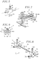
- la figure 5 est une vue en perspective partiellement éclatée d'une seconde griffe vertébrale montée à coulissement sur une tige de consolidation ;
- la figure 6 est une vue en perspective schématique d'un dispositif d'ostéosynthèse comprenant plusieurs tiges de consolidation reliées par des moyens transversaux et longitudinaux de stabilisation ;
- la figure 7 est une vue en perspective partiellement éclatée d'un premier moyen transversal de stabilisation à plaque crantée ;
- la figure 8 est une vue en perspective éclatée d'un second moyen transversal de stabilisation à barre filetée ; et
- la figure 9 est une vue transversale en bout d'un raccord longitudinal de stabilisation pour deux tiges de consolidation.
- Figure 1 is an exploded perspective view of a base assembly between a pedicle screw and a consolidation rod in an osteosynthesis device according to the invention;
- Figure 2 is a perspective view of a first fastener for connecting a consolidation rod to an element with a threaded section such as pedicle screw or first vertebral claw;
- Figure 3 is a perspective view of a second fastener for connecting a consolidation rod to a threaded section member;
- FIG. 4 is an exploded perspective view of another basic assembly between a consolidation rod and a vertebral claw with threaded section in an osteosynthesis device according to the invention;
- Figure 5 is a partially exploded perspective view of a second spinal claw slidably mounted on a consolidation rod;
- Figure 6 is a schematic perspective view of an osteosynthesis device comprising several consolidation rods connected by transverse and longitudinal stabilization means;
- Figure 7 is a partially exploded perspective view of a first transverse notch plate stabilization means;
- Figure 8 is an exploded perspective view of a second transverse thread bar stabilizing means; and
- FIG. 9 is a transverse end view of a longitudinal stabilization connector for two consolidation rods.
Un dispositif d'ostéosynthèse selon l'invention comprend au moins un assemblage de base pour relier une tige de consolidation 1 à un élément à tronçon fileté, qui est constituée par une vis pédiculaire 2 selon la figure 1, par l'intermédiaire d'un moyen de liaison rapide 3. Ces divers éléments et d'autres cités par la suite sont essentiellement métalliques, par exemple en un alliage à base de titane.An osteosynthesis device according to the invention comprises at least one basic assembly for connecting a
La vis pédiculaire 2 est en forme de goujon et est composée d'une partie partiellement filetée 20-21 sensiblement tronconique, d'un tronçon cylindrique 22 fileté sensiblement sur toute sa longueur, et d'une tête de préhension intermédiaire 23, ici à section hexagonale, située entre les partie et tronçon filetés.The
La partie 20-21 comprend, sensiblement sur la moitié de sa longueur, un tronçon sensiblement tronconique 20 ayant un pas de filetage rond relativement large, terminé par une extrémité autotaraudeuse à pointe mousse 201, c'est-à-dire une pointe comportant deux rainures axiales opposées avec une section en vé, de manière à pénétrer facilement et être ancré intimement dans l'os spongieux d'un corps vertébral. Un tronçon tronconique 21 disposé entre le tronçon 20 et la tête 23 complète la partie de vis 20-21. Le tronçon 21 est recouvert d'un revêtement rugueux en titane pur poreux afin que ses micro-anfractuosités soient comblées par croissance osseuse du pédicule vertébral où il est implanté. Cet ancrage du tronçon rugueux 21 dans le pédicule assure une stabilité primaire au dispositif, contrairement à une liaison fibreuse avec un tronçon lisse de vis connue en alliage de Nickel-Chrome ou Cobalt-Chrome traversant le pédicule. La tête de préhension 23 est destinée à être prise par une clé de manoeuvre correspondante pour visser le tronçon fileté 20 dans les pédicule et corps vertébral jusqu'à ce que la tête 23 bute contre l'os cortical.The part 20-21 comprises, substantially over half of its length, a substantially
Le second tronçon fileté 22 constitue l'extrémité postérieure extra-vertébrale de la vis 2 après implantation, et est destiné à coopérer avec le moyen de liaison 3 et à recevoir un écrou 24. Comme montré en 22a à la figure 6, ce tronçon fileté postérieur 22 est conçu initialement relativement long de manière à adapter sa longueur par sciage préopératoire. La face extrême du tronçon fileté 22 comporte une fente 221 pour recevoir un tournevis, comme illustré à la figure 1, ou bien une extrémité polygonale, par exemple hexagonale, pour coopérer avec une clé de manoeuvre de manière à empêcher la rotation éventuelle de la vis 2 lors du serrage du moyen de liaison 3 par l'écrou 24, comme on le verra par la suite.The second threaded
Comme montré aux figures 1 et 2, un moyen de liaison rapide est une attache 3 se présentant sensiblement sous la forme d'un petit pavé qui est partagé en deux faces antérieure et postérieure symétriques par rapport à une fente 35. Des premières moitiés, ici biseautées trapézoïdalement, des faces antérieure et postérieure de l'attache 3, sensiblement "verticales" après implantation du dispositif, sont percées parallèlement en un alésage lisse 30 recevant à coulissement la tige 1. Des secondes moitiés des deux faces antérieure et postérieure de l'attache 3 sont percées perpendiculairement par un second alésage lisse 31 qui est perpendiculaire au premier alésage 30 et non concourant avec ce dernier. L'alésage 31 a une section contenue dans les sections polygonales de la tête 242 de l'écrou 24 et de la tête 23 de la vis 2. Le tronçon fileté 22 d'une vis 2 notamment est reçu librement dans l'alésage 31.As shown in Figures 1 and 2, a quick connection means is a
Les extrémités du premier alésage 30 offrent des fraisures 32 facilitant la pénétration de la tige 1 dans l'alésage 30. Sur la face postérieure de l'attache 3 est prévu un petit trou taraudé 33 débouchant radialement dans le premier alésage lisse 30 afin qu'une petite vis de pression sans tête à six pans creux 34 vissée dans le trou 33 maintienne immobile l'attache 3 sur la tige 1 à une position temporaire souhaitée.The ends of the
L'attache 3 comporte également deux fentes rectangulaires 35 et 36 qui s'étendent sensiblement perpendiculairement l'une à l'autre à partir d'une face "latérale" de l'attache qui est parallèle à l'alésage 30 et opposée à l'alésage 30 par rapport à l'alésage 31 et qui est orientée sensiblement vers la gauche ou droite après implantation du dispositif (figure 6). La première fente 35 est pratiquée suivant un plan sensiblement médian de l'attache coplanaire à l'axe de l'alésage 30. La fente 35 est traversée perpendiculairement par l'alésage 31, débouche axialement dans l'alésage 30, et a une largeur très nettement inférieure au diamètre de la tige 1 et de l'alésage 30. La seconde fente 36 débouche axialement dans le second alésage 31, est sensiblement perpendiculaire au premier alésage 30, et offre une largeur supérieure au diamètre du tronçon fileté de vis 22 et inférieure au diamètre de l'alésage 31. Le second alésage 31 reçoit une jupe complémentaire cylindrique à extrémité chanfreinée 241 qui est disposée sous la tête polygonale 242 de l'écrou 24. La jupe 241 est plus courte que l'alésage 31 et a un diamètre sensiblement égal au diamètre de l'alésage 31 et plus grand que la largeur de la fente 36 afin que la jupe ne s'échappe pas de l'attache après serrage de l'écrou 24.The
La réalisation illustrée à la figure 1 évite avantageusement un glissement latéral de l'attache 3 par rapport à la vis 2 lors de l'assemblage de ces derniers, grâce à l'emprisonnement de la jupe 241 dans l'alésage 31 qui est plus large que la fente 36, bien que le tronçon fileté 22 passe à travers la fente 35 pendant l'assemblage du dispositif.The embodiment illustrated in Figure 1 advantageously avoids lateral sliding of the
Ainsi il apparaît que l'attache 3 constitue un collier serrant la tige 1 et de liaison de la tige 1 à la vis 2. La tige coulisse dans l'alésage 30 lors de l'assemblage et positionnement de différentes pièces du dispositif d'ostéosynthèse et après implantation de la vis 2. Les faces antérieure et postérieure de l'attache 3 sont enserrées entre la tête de vis 23 et la tête d'écrou 242 de manière à fléchir sensiblement lesdites faces l'une vers l'autre et rétrécir la première fente 35 pour bloquer par pinçage la tige 1, et simultanément lier rapidement et solidement la vis 1 à l'attache 3 et donc à la tige 1. Grâce à la faible largeur de la première fente 35 de l'attache 3, la quasi-totalité de la périphérie circulaire du tronçon de la tige 1 contenue dans l'alésage 30 est pincée dans le premier alésage 30 qui, initialement fendu, se referme et cintre la tige 1. Ce pinçage quasi-total empêche tout glissement de l'attache 3 le long et/ou autour de la tige 1, et ainsi confère une surface porteuse davantage étendue et une liaison davantage rigide entre la tige et la vis 2 comparativement à la technique antérieure. Lors du vissage de l'écrou 24 et du rétrécissement de la fente 35, la vis 2 est maintenue immobile, le cas échéant, par la tête 23 ou la fente 221.Thus it appears that the
En outre, un relâchement du pinçage de la tige 1 par l'alésage 30 pour modifier les positions relatives de la vis 2 et de la tige 1 est obtenu en dévissant faiblement l'écrou 24, tout en maintenant encore la jupe 241 dans l'alésage 31 afin que le tronçon fileté 22 ne s'échappe pas par la fente 36.In addition, a loosening of the pinching of the
Selon une autre variante montrée à la figure 3, une attache de liaison 3a présente, d'une manière analogue à l'attache 3 à la figure 2, un premier alésage lisse 30a dans lequel débouche une première fente 35a axiale à cet alésage, un second alésage lisse 31a perpendiculaire à l'alésage 30a, et un petit trou taraudé 33a pour vis de serrage 34a, radial à l'alésage 30. Dans l'attache 3a est ménagée une seconde fente 36a qui, comme la fente 36 dans la première attache 3, débouche axialement dans le second alésage 31 et est perpendiculaire à la première fente 35a, mais qui est pratiquée latéralement dans une face "supérieure" ou "inférieure" de l'attache 3a sensiblement parallèlement, et non perpendiculairement, au premier alésage 30a.According to another variant shown in FIG. 3, a connecting
L'invention prévoit ainsi deux types d'attache à fente latérale 36a, selon que la fente 36a est orientée vers le "haut", ou vers le "bas" en direction du coccyx, comme montré à la figure 6.The invention thus provides two types of attachment with
Ces trois types d'attache, en conjugaison avec le montage à coulissement et rotation de l'alésage 30, 30a sur la tige 1, permettent ainsi d'aborder le tronçon fileté 22 d'une vis 3 (ou celui 41 d'une griffe vertébrale 4; figure 4) quasiment par n'importe quelle direction. En particulier, l'une choisie de ces attaches peut relier une tige 1 à une vis, quelle que soit l'orientation de la tige par rapport à la vis, dans un plan sensiblement perpendiculaire à la vis. Les petites vis de serrage temporaire 34, 34a assistent au maintien des attaches correspondantes 3, 3a à des positions souhaitées le long d'une tige commune 1 lorsque plusieurs attaches 3, 3a montées sur la tige 1 doivent être engagées par les fentes 36, 36a et les alésages 31, 31a simultanément dans des tronçons filetés 22 de vis correspondantes 2 (ou tronçons filetés 41 de griffes 4; figure 4).These three types of attachment, in conjunction with the sliding and rotation mounting of the
L'assemblage entre une tige 1, un élément à tronçon fileté telle qu'une vis 2, et une attache 3, 3a comprend, en outre de préférence, un moyen traversé par le tronçon fileté 22 de la vis 2 et disposé entre la tête de vis 23 et la tête d'écrou 242 pour amortir des micro-déplacements relatifs entre la tige 1 et la vis 2. Ce moyen pour amortir contribue ainsi à annuler des micro-déplacements rachidiens d'une vertèbre à l'autre et donc d'une vis pédiculaire à l'autre et ainsi à éviter des fêlures ou fractures de la vis 2 et/ou de la tige 1. Ce moyen pour amortir comprend une rondelle 25 en matériau amortissant, tel qu'élastomère ou polyuréthanne ou silicone, enfilé sur le tronçon fileté 22. Selon la réalisation illustrée à la figure 1, cette rondelle 25 est entretoisée par deux rondelles de guidage métalliques 26, qui sont de préférence termocollées à la rondelle 25; cet ensemble de rondelles 25 + 26 est enfilé autour du tronçon 22 et est enserré à la base du tronçon 22, entre la tête de vis 23 et la face antérieure de l'attache 3, ou 3a.The assembly between a
Selon d'autres variantes, ce premier assemblage de rondelles ne peut comporter qu'une rondelle 25 en matériau amortissant et une seule rondelle métallique 26. Un second assemblage de rondelles comportant au moins une rondelle en matériau amortissant soit remplace le premier assemblage de rondelles, soit est combiné avec celui-ci, et est disposé entre la face postérieure de l'attache 3, 3a et la tête 242 de l'écrou 24.According to other variants, this first assembly of washers can only comprise one
En référence à la figure 4, l'élément à tronçon fileté constitué précédemment par une vis 2 est ici sous la forme d'une première griffe vertébrale 4. Cette griffe 4 comporte également un tronçon fileté cylindrique 41 destiné à recevoir un écrou 24 et à pénétrer dans un second alésage 31, 31a d'attache 3, 3a à travers la seconde fente 36, 36a de cette attache; à titre d'exemple, la figure 4 montre un assemblage de griffe 4 avec une attache 3a à seconde fente latérale 36a. Sous-jacente au tronçon fileté 41 de la griffe 4 est prévue une partie en forme de demi-croissant sensiblement circulaire 42, formant une "griffe", qui est séparée du tronçon fileté 41 par une tête rectangulaire 43 et qui est terminée par une extrémité sensiblement pointue 44. La partie 42 est destinée à accrocher des bordures de divers évidemments des vertèbres notamment pédiculaires, lombaires, thoraciques, sus-laminaires, sous-laminaires, et transversaires. Comme pour la vis 2, la griffe 4 peut être abordé sensiblement latéralement, par la droite ou la gauche, ou par le haut ou le bas, par l'une des trois attaches 3, 3a, et sa partie en forme de demi-croissant 42 peut-être orientée selon une direction quelconque grâce à la rotation du tronçon fileté 41 dans l'alésage 31, 31a de l'attache 3, 3a.With reference to FIG. 4, the element with a threaded section previously constituted by a
Une seconde griffe 5 analogue à la griffe précédente 4 est montrée à la figure 5. Cette seconde griffe 5 comporte une partie en forme de demi-croissant 52 analogue à la partie 42, et une tête parallélépipédique 53 comportant un alésage 55 qui est monté à coulissement sur une tige de consolidation 1. Selon la réalisation illustrée à la figure 5, la pointe 54 de la griffe est située dans un plan axial à l'alésage 55; toutefois, selon d'autres réalisations, la partie en forme de demi-croissant 52 peut être orientée d'une manière quelconque et en fonction des besoins autour d'un axe médian de la tête 53 perpendiculaire à l'alésage 55. Le long de cet axe médian est ménagé un trou taraudé 51 à partir de la face souvent postérieure de la tête 53 opposée à la partie en forme de demi-croissant 52 et débouchant radialement dans l'alésage 55. Une petite vis de pression 56 sans tête à six pans creux pénètre dans le trou 51 de manière à bloquer en translation et en rotation la tige 1 dans l'alésage 55, et ainsi maintenir la griffe 5 sur la tige 1. Une telle seconde griffe 5 montée à coulissement sur la tige 1 peut être ancrée par exemple dans une apophyse transverse ou épineuse d'une vertèbre.A
La figure 6 montre schématiquement en vue latéro-postérieure, à titre d'exemple, un ensemble rigide de diverses pièces pouvant entrer dans la constitution d'un dispositif d'ostéosynthèse pour consolidation rachidienne selon l'invention. Dans ce dispositif on y retrouve des vis pédiculaires 2 avec des écrou 24 et moyen amortissant 25 + 26 ainsi que des premières griffes 4 avec écrou 24 qui sont reliées à plusieurs tiges 1, ici au nombre de trois 1a, 1b et 1c, par l'intermédiaire d'attaches correspondantes 3 et 3a ainsi qu'une seconde griffe vertébrale 5 fixée autour de la tige 1c.FIG. 6 schematically shows in latero-posterior view, by way of example, a rigid assembly of various parts which can enter into the constitution of an osteosynthesis device for spinal consolidation according to the invention. In this device there are
Les première et seconde tiges 1a et 1b sont deux tiges à relier à des ensembles de vis respectivement situés à droite et à gauche de l'apophyse épineuse du rachis et sont donc disposées sensiblement côte à côte grâce à au moins l'un de deux moyens transversaux de stabilisation 6 et 7.The first and
Les première et troisième tiges 1a et 1c sont disposées le long du même coté de l'apophyse épineuse, par exemple le côté droit. La troisième tige 1c peut être destinée à prolonger une consolidation rachidienne déjà effectuée par les moyens liés à la première tige 1a; un moyen longitudinal de stabilisation 8 est donc prévu entre des extrémités des tiges 1a et 1c.The first and
Le premier moyen transversal de stabilisation 6 est montré à la figure 7 et comprend une plaque de stabilisation sensiblement rectangulaire allongée 60, deux premiers crochets de tige 61 ainsi que deux écrous 62 et deux rondelles crantées 63.The first transverse stabilization means 6 is shown in FIG. 7 and comprises an elongated substantially
La plaque 60 présente une face antérieure lisse 601 à appliquer sur les deux tiges 1a et 1b et une face postérieure 602 ayant des petites crénelures parallèles propres à engrener avec des faces crantées 632 des deux rondelles 63. Deux lumières oblongues 603 sont ménagées longitudinalement dans la plaque 60 pour être disposée sensiblement transversalement aux tiges 1a et 1b. Selon une autre variante, les deux lumières sont remplacées par une lumière plus longue.The
Les crochets 61 ont une forme analogue au premières griffes vertébrales 4, tel que celle montrée à la figure 4, mais ont une taille réduite sensiblement de moitié comparativement aux griffes 4. Ainsi un crochet 61 comporte un tronçon fileté 611 et une partie de prise en forme de demi-croissant circulaire 612 ainsi qu'une tête rectangulaire 613 entre le tronçon 611 et la partie 612.The
D'une part, la longueur de la tête de crochet 613 est sensiblement inférieure à celle des lumières 603 dans la plaque 60. D'autre part, la surface concave sensiblement semi-circulaire 615 du crochet 61 a un diamètre sensiblement supérieur au diamètre D1 des tiges 1a, 1b et présente une ouverture latérale 614 dont les surfaces parallèles sont sensiblement inclinées par rapport à l'axe du tronçon fileté 611 et vers le tronçon 611, et donc par rapport à la plaque 60 après serrage. Ces deux conditions permettent à une tige 1a, 1b logée dans le fond de la surface concave 615 du crochet d'être poussée par une plaque 60 dont une lumière encadre largement la tête 613, sans que la tige 1a, 1b, ne puisse s'échapper du crochet 61. La distance H6 entre la surface lisse 601 de la plaque et la pointe 614 du crochet est alors inférieure au diamètre D1 de la tige, comme montré à droite dans la figure 7.On the one hand, the length of the
Cette liaison rigide entre la partie en forme de demi-croissant 612 d'un crochet 61 et une plaque 60 est obtenue :
- (a) en crochetant la tige correspondante 1a, 1b par la surface concave 615,
- (b) en introduisant à coulissement la tête de crochet 613 dans une lumière 603 de la plaque,
- (c) en enfilant une rondelle crantée 602 sur le tronçon fileté 611 saillant de la
face crénelée 602, au-dessus de la lumière 603, - (d) en engrenant les crans de la rondelle crantée 63 dans les crénelures de la
face 602, et - (e) finalement en vissant l'écrou 62 sur le tronçon 611 de manière à ce que l'écrou avec la surface concave de crochet 615 ensert la rondelle 63, la
plaque 60 au niveau de la lumière 603, et la tige correspondante 1a, 1b.
- (a) by hooking the
corresponding rod concave surface 615, - (b) sliding the
hook head 613 into aslot 603 in the plate, - (c) by threading a notched
washer 602 on the threadedsection 611 projecting from thecrenellated face 602, above thelumen 603, - (d) by meshing the notches of the notched
washer 63 in the notches of theface 602, and - (e) finally by screwing the
nut 62 onto thesection 611 so that the nut with the concave surface of thehook 615 encloses thewasher 63, theplate 60 at the level of theslot 603, and thecorresponding rod
Deux premiers crochets 61 sont ainsi montés sur deux tiges 1a et 1b et reliés par une plaque commune 60. Les crochets peuvent être disposés dos-à-dos entre les tiges 1a et 1b comme montré à la figure 7, ou bien face-à-face à l'extérieur de l'ensemble des deux tiges, ou bien encore en série et respectivement à l'extérieur et à l'intérieur de l'ensemble des deux tiges.Two
Les deux tiges 1a et 1b peuvent être stabilisées par deux plaques 60 et quatre crochets 61 en formant un quadrilatère indéformable de manière à consolider l'assemblage de ces pièces en contraction ou en décontraction, comme montré à la figure 6. A cet égard, l'écartement à des extrémités des tiges 1a et 1b peut être augmenté ou diminué, après desserrage des écrous 62 de la plaque de stabilisation 60 et dégagement des rondelles crantées 63 de la face de plaque 602, en éloignant ou rapprochant les crochets de tige et rondelles crantées correspondants 61 et 63 par coulissement des crochets dans les lumières 603 de la plaque 60.The two
Un second moyen transversal de stabilisation 7 comprend, en référence à la figure 8, une barre mince 70 ainsi que deux seconds crochets de tige 71 munis chacun d'une petite vis de pression 72 sans tête et à six pans creux.A second transverse stabilization means 7 comprises, with reference to FIG. 8, a
La barre 70 comporte une partie centrale cylindrique lisse 701 séparant deux parties extrêmes filetées 702 qui offrent des méplats longitudinaux coplanaires 703 parallèles à l'axe de la barre 70.The
Chacun des seconds crochets de tige 71 a une forme analogue à une seconde griffe vertébrale 5, telle que celle montrée à la figure 5, mais ayant une taille réduite sensiblement de moitié. Ainsi un crochet 71 comporte une tête parallélépipédique 713 et une partie de prise sensiblement en forme de demi-croissant circulaire 712 pour crocheter une tige 1a, 1b. La tête 713 comporte un trou demi-taraudé oblong 717 qui s'étend parallèlement à la partie de prise en crochet 712 et perpendiculairement à la tige 1a, 1b crocheté par celle-ci. Perpendiculairement à la face postérieure de la tête 713 et dans le prolongement axial d'une section oblongue du trou 717 est pratiquée un trou taraudé 711 pour recevoir une vis de pression 72 perpendiculaire à la fois à la barre 70 et à la tige 1a, 1b après assemblage.Each of the second rod hooks 71 has a shape analogous to a second
Le trou 717 est partagé, en section transversale, en une première portion longitudinale concave au moins partiellement taraudée 718 et une seconde portion longitudinale concave lisse 719 par rapport à un plan parallèle à l'axe du trou 717 et perpendiculaire au trou 711. La section oblongue du trou 718 est plus longue et au moins sensiblement aussi large que le diamètre des parties filetées de barre 702. La première portion 718 est de préférence taraudée au moins au fond avec un filetage correspondant aux parties filetées 702 de la barre 70 et est disposée à l'opposé du trou taraudé 711 par rapport à l'axe du trou 717, vers la partie antérieure en forme de demi-croissant 712. La seconde portion lisse 719 est disposée vers la face postérieure du trou 717, et le trou taraudé 711 débouche transversalement dans cette portion lisse.The
Le second moyen de stabilisation 7 est monté de la manière suivante.The second stabilization means 7 is mounted in the following manner.
Chacun des seconds crochets 71 dont les trous oblongs demi-taraudés 717 ont été dégagés des vis 72, sont enfilés sur les parties extrêmes filetées 702 de la barre 70 de part et d'autre des deux tiges 1a et 1b et sont disposés avec leurs parties 712 en forme de demi-croissant circulaire, par exemple en regard l'une de l'autre comme montré à la figure 8. Après crochetage des tiges 1a et 1b par les parties de prise 712, pour tenter de les rapprocher selon la figure 8, ou de les éloigner selon d'autres variantes déjà évoquées pour les crochets 61, les parties filetées de barre 702 sont engrenées dans les portions taraudées 718 des trous 717. Ces engrènements sont maintenus en vissant dans les trous 711 les vis 72 dont les bouts plats poussent les méplats 703 contre les portions taraudées 718. Dans ces conditions, la barre 70 est arrêtée aussi bien en rotation grâce à la pression des vis 72 exercée sur les méplats 703, qu'en translation axiale grâce à l'engrènement autobloquant du filetage des parties de barre 702 dans le taraudage des portions de trou demi-taraudé 718.Each of the second hooks 71, the oblong half-tapped
Cet assemblage est très résistant contre tout écartement ou éloignement des crochets 71 grâce au nombre relativement élevé des filets coopérant entre les portions de trou 718 et les parties de barre 702. En outre, cet assemblage est rapide à monter ou démonter, sans nécessiter un dévissage long des extrémités de barre 702, puisque celles-ci sont posées dans les trous oblongs 718.This assembly is very resistant against any separation or removal of the
Comme montré aux figures 6 et 9, le moyen longitudinal de stabilisation est sous la forme d'un raccord de tiges 8. Ce raccord 8 a une forme parallélépipédique dans laquelle est ménagée un orifice longitudinal 81 à section transversale oblongue. La largeur de l'orifice 81 et le diamètre des parois extrêmes semi-circulaires 810 de l'orifice 81 sont sensiblement égaux au diamètre D1 des tiges 1a, 1c. La face postérieure du raccord 8 est percée d'un trou taraudé 82 débouchant transversalement et centralement dans l'orifice oblong 81. Le trou 82 est propre à recevoir une petite vis-pointeau 83 sans tête à six pans creux ayant un bout pointu lisse tronconique 84.As shown in Figures 6 and 9, the longitudinal stabilizing means is in the form of a connecting
La hauteur H8 (longueur transversale) de l'orifice 81 est supérieure à la somme des diamètres des tiges 1a et 1c, mais inférieure à la somme des diamètres des tiges 1a et 1c et de la vis-pointeau 83. Dans ces conditions, après avoir enfilé les extrémités des deux tiges 1a et 1c dans l'orifice oblong 81, la vis-pointeau 83 est vissée dans l'orifice 82 afin que son bout pointu tronconique 84 écarte progressivement les tiges 1a et 1c et les coince fermement contre les parois semi-circulaires en regard 810 du trou 81, ce qui relie définitivement et solidement les deux tiges 1a et 1c.The height H8 (transverse length) of the
Selon d'autres variantes, un raccord présente un orifice 81 ayant une hauteur plus élevée pour y relier par coinçage plusieurs tiges côte à côte. Par exemple, ladite hauteur H8 est supérieure à la somme des diamètres de trois, respectivement quatre tiges de consolidation et inférieure à la somme des diamètres des trois respectivement quatre tiges et des diamètres de deux, respectivement trois vis-pointeau vissées transversalement dans le raccord et ayant chacune une extrémité tronconique disposée entre deux tiges respectives.According to other variants, a connector has an
Claims (19)
- An osteosynthesis device comprising a rod (1), a member (2;4) having a threaded section (22;41) extending from a head (23;43) and fitted with a nut (24), and a connecting fastener (3), the fastener (3) comprising a first bore (30) passed through by said rod (1), a first slit (35) opening axially into the first bore, and a second bore (31) substantially perpendicular to the first slit (35) and passed through by a portion of said threaded section (22;41) located between the member head and the nut,
characterized bythe smooth character of the first bore (30), anda second slit (36) perpendicularly to the first slit (35), opening axially into the second bore (31) and having a width greater than the diameter of said threaded member section (22;41). - Device according to the claim 1, characterized in that it comprises a cylindrical shank (241) of the nut (24) having a diameter that is substantially equal to the diameter of the second bore (31) and more than the width of the second slit (36).
- Device according to the claim 1 or 2, characterized in that the second slit (36;36a) extends substantially perpendicular to the first bore (30;30a).
- Device according to any one of claims 1 to 3, characterized in that the fastener (3) comprises a locking means (34) radial to the first bore (30) in order to temporarily maintain the fastener (3) motionless on the rod (1).
- Device according to any one of claims 1 to 4, comprising a means (25;26) passed through by the threaded section (22;41) and provided between the member head (23;43) and the nut (24) for damping relative movements between the rod (1) and said member (2;4).
- Device according to the claim 5, characterized in that the damping means comprises a washer made of damping material (25), which is preferably in contact with one or two metal washers (26).
- Device according to any one of claims 1 to 6, characterized in that said member (2) comprises a portion (20-21) which is at least partially threaded and separated from said threaded section (22) by the head (23).
- Device according to any one of claims 1 to 6, characterized in that said member (4) comprises a claw-shaped portion (42) separated from said threaded section (41) by the head (43).
- Device according to any one of claims 1 to 8, comprising a means (5) having a bore slidably passed through by the rod (1) and having a claw-shaped portion (52), and a locking means (56) radial to the rod for maintaining motionless said means slidably passed through (5) by the rod (1).
- Device according to any one of claims 1 to 9, comprising a second rod (1b) disposed laterally to the previously mentioned first rod (1a), and a first transversal stabilizing means (6) connecting the first and second rods.
- Device according to any one of claims 1 to 9, comprisinga second rod (1b) disposed laterally to the previously mentioned first rod (1a),a plate (60) transversal to the rods,two hooks (61) each having a threaded section (611) passing through a slot (603) of the plate and a holding portion (612) partially surrounding respective one of first and second rods (1a, 1b), and two nuts (62) respectively screwed onto threaded hook sections (611) for tightening the plate (60) against the first and second rods (1a, 1b) thereby confining the rods between the plate and the hook holding portions (612).
- Device according to the claim 11, characterized in that the holding portion (612) of each hook (61) is located into the slot (603) and has an opening (614) substantially inclined in relation to and towards the threaded section (611) of said hook.
- Device according to the claim 11 or 12, characterized in that one (602) of sides of the plate (60) is indented thereby cooperating with notched washers (63) slid over the threaded sections (611) of the hooks (61).
- Device according to any one of the claims 1 to 9, comprising :a second rod (1b), disposed laterally to the previously mentioned first rod (1a),a bar (70) transversal to the rods,two hooks (71) having hooking portions (712) to be hooked to the rods, andmeans (717, 72) for quickly securing the hooks to ends (702, 703) of the bar.
- Device according to the claim 14, characterized in thatthe ends (702, 703) of the bar (70) each comprise a longitudinal threaded section (702) and a longitudinal flat surface (703), andthe securing means in each of the shooks (79) comprise an oblong hole (717) for free racommodating one of the bar ends (702,703),said hole having a tapped longitudinal portion (718) for meshing with the tapped portion of said one of said bar ends, and a smooth portion (719) into which opens a tapped hole (711) containing a locking screw (72) pressed against said flat surface (703) of said one of the bar ends.
- Device according to any one of claims 1 to 15, comprising a third rod (1c) substantially parallel to the first rod (1a), and a longitudinal stabilizing means (8) connecting the ends of the rods.
- Device acording to any one of claims 1 to 15, comprisinga third rod (1c) substantially parallel to the first rod (1a), anda connector (8) having a longitudinal orifice (81) with an oblong cross-section passed through by the first and third rods, anda means (83) for spacing apart the first and third rods thereby blocking the first and third rods in said orifice (81).
- Device according to the claim 17, characterized in that said spacing means comprises a screw (83) having a pointed end (84) which opens transversely into said orifice (81) of the connector and between the first and third rods (1a, 1c) and wedges the first and third rods against opposite walls (810) of the hole (81).
- Device according to any one of claims 1 to 15, comprising plural rods (1a, 1b, 1c), a connector (8) having a longitudinal orifice (81) with an oblong cross-section passed through by said rods, and plural means (83) fewer by one unit in number than the rods for each spacing apart respective two rods thereby blocking rods in said orifice.
Applications Claiming Priority (2)
| Application Number | Priority Date | Filing Date | Title |
|---|---|---|---|
| FR9213414 | 1992-11-06 | ||
| FR9213414A FR2697742B1 (en) | 1992-11-06 | 1992-11-06 | Osteosynthesis device for spinal consolidation. |
Publications (2)
| Publication Number | Publication Date |
|---|---|
| EP0596788A1 EP0596788A1 (en) | 1994-05-11 |
| EP0596788B1 true EP0596788B1 (en) | 1996-12-11 |
Family
ID=9435322
Family Applications (1)
| Application Number | Title | Priority Date | Filing Date |
|---|---|---|---|
| EP93402676A Expired - Lifetime EP0596788B1 (en) | 1992-11-06 | 1993-10-29 | Osteosynthesis device for spinal consolidation |
Country Status (10)
| Country | Link |
|---|---|
| US (1) | US5380325A (en) |
| EP (1) | EP0596788B1 (en) |
| JP (1) | JP2666683B2 (en) |
| KR (1) | KR940010975A (en) |
| AT (1) | ATE146064T1 (en) |
| CA (1) | CA2109457C (en) |
| DE (1) | DE69306536T2 (en) |
| ES (1) | ES2096249T3 (en) |
| FR (1) | FR2697742B1 (en) |
| GR (1) | GR3022754T3 (en) |
Cited By (1)
| Publication number | Priority date | Publication date | Assignee | Title |
|---|---|---|---|---|
| US7744632B2 (en) | 2006-12-20 | 2010-06-29 | Aesculap Implant Systems, Inc. | Rod to rod connector |
Families Citing this family (187)
| Publication number | Priority date | Publication date | Assignee | Title |
|---|---|---|---|---|
| WO1991016020A1 (en) * | 1990-04-26 | 1991-10-31 | Danninger Medical Technology, Inc. | Transpedicular screw system and method of use |
| US5810817A (en) * | 1992-06-19 | 1998-09-22 | Roussouly; Pierre | Spinal therapy apparatus |
| US5947965A (en) * | 1992-12-31 | 1999-09-07 | Bryan; Donald W. | Spinal fixation apparatus and method |
| US5498262A (en) * | 1992-12-31 | 1996-03-12 | Bryan; Donald W. | Spinal fixation apparatus and method |
| FR2704133B1 (en) * | 1993-04-19 | 1995-07-13 | Stryker Corp | Implant for osteosynthesis device in particular of the spine. |
| US5611800A (en) * | 1994-02-15 | 1997-03-18 | Alphatec Manufacturing, Inc. | Spinal fixation system |
| FR2719759B1 (en) * | 1994-05-16 | 1996-08-30 | Charles Khalife | Intervertebral osteosynthesis system, in particular with transverse reinforcement device. |
| US5542946A (en) * | 1994-05-27 | 1996-08-06 | Sofamor S.N.C. | Hook for an occipito-cervical rod or plate of an occipito-cervical osteosynthesis instrumentation |
| US5620443A (en) * | 1995-01-25 | 1997-04-15 | Danek Medical, Inc. | Anterior screw-rod connector |
| US5697895A (en) * | 1996-05-15 | 1997-12-16 | Bremer; Ross L. | Halo ring with longitudinally and angularly adjustable pins |
| US6171311B1 (en) | 1996-10-18 | 2001-01-09 | Marc Richelsoph | Transverse connector |
| CA2264672C (en) | 1996-10-24 | 2010-11-30 | Spinal Concepts, Inc. | Method and apparatus for spinal fixation |
| US6416515B1 (en) | 1996-10-24 | 2002-07-09 | Spinal Concepts, Inc. | Spinal fixation system |
| US6045579A (en) | 1997-05-01 | 2000-04-04 | Spinal Concepts, Inc. | Adjustable height fusion device |
| US5928243A (en) * | 1997-07-16 | 1999-07-27 | Spinal Concepts, Inc. | Pedicle probe and depth gage |
| US6454769B2 (en) | 1997-08-04 | 2002-09-24 | Spinal Concepts, Inc. | System and method for stabilizing the human spine with a bone plate |
| US6030389A (en) * | 1997-08-04 | 2000-02-29 | Spinal Concepts, Inc. | System and method for stabilizing the human spine with a bone plate |
| US6053921A (en) * | 1997-08-26 | 2000-04-25 | Spinal Concepts, Inc. | Surgical cable system and method |
| US5964769A (en) | 1997-08-26 | 1999-10-12 | Spinal Concepts, Inc. | Surgical cable system and method |
| US6749361B2 (en) | 1997-10-06 | 2004-06-15 | Werner Hermann | Shackle element for clamping a fixation rod, a method for making a shackle element, a hook with a shackle element and a rode connector with a shackle element |
| US6179838B1 (en) | 1998-02-24 | 2001-01-30 | Daniel Fiz | Bone fixation arrangements and method |
| US5944720A (en) * | 1998-03-25 | 1999-08-31 | Lipton; Glenn E | Posterior spinal fixation system |
| DE19914232B4 (en) * | 1999-03-29 | 2012-08-30 | Signus Medizintechnik Gmbh | Device for stabilizing vertebral bodies of a spinal column |
| US6315779B1 (en) * | 1999-04-16 | 2001-11-13 | Sdgi Holdings, Inc. | Multi-axial bone anchor system |
| US6423067B1 (en) | 1999-04-29 | 2002-07-23 | Theken Surgical Llc | Nonlinear lag screw with captive driving device |
| ES2154227B1 (en) * | 1999-06-30 | 2001-11-16 | Surgival Co S A | POLYAXIAL SYSTEM OF FIXATION OF VERTEBRAS. |
| US6238396B1 (en) * | 1999-10-07 | 2001-05-29 | Blackstone Medical, Inc. | Surgical cross-connecting apparatus and related methods |
| EP1244387B1 (en) * | 1999-12-24 | 2005-12-14 | Societe De Fabrication De Materiel Orthopedique Sofamor | Pedicle screws with inclined channels to hold support rods |
| US6331179B1 (en) | 2000-01-06 | 2001-12-18 | Spinal Concepts, Inc. | System and method for stabilizing the human spine with a bone plate |
| US6613049B2 (en) * | 2000-02-02 | 2003-09-02 | Robert A. Winquist | Adjustable bone stabilizing frame system |
| US6645207B2 (en) | 2000-05-08 | 2003-11-11 | Robert A. Dixon | Method and apparatus for dynamized spinal stabilization |
| US6524310B1 (en) | 2000-08-18 | 2003-02-25 | Blackstone Medical, Inc. | Surgical cross-connecting apparatus having locking lever |
| FR2816196B1 (en) * | 2000-11-07 | 2003-01-03 | Medicrea | VERTEBRAL ARTHRODESIS MATERIAL |
| US7651516B2 (en) * | 2000-12-01 | 2010-01-26 | Spinevision S.A. | Connection assembly for the field of spinal osteosynthesis and method for using at least one such assembly |
| US8123814B2 (en) | 2001-02-23 | 2012-02-28 | Biomet Manufacturing Corp. | Method and appartus for acetabular reconstruction |
| US7597715B2 (en) | 2005-04-21 | 2009-10-06 | Biomet Manufacturing Corp. | Method and apparatus for use of porous implants |
| US20060064092A1 (en) * | 2001-05-17 | 2006-03-23 | Howland Robert S | Selective axis serrated rod low profile spinal fixation system |
| US7314467B2 (en) * | 2002-04-24 | 2008-01-01 | Medical Device Advisory Development Group, Llc. | Multi selective axis spinal fixation system |
| US20040243128A1 (en) * | 2001-05-17 | 2004-12-02 | Howland Robert S. | Selective axis posterior lumbar spinal plating fixation apparatus and methods for use |
| US6770075B2 (en) | 2001-05-17 | 2004-08-03 | Robert S. Howland | Spinal fixation apparatus with enhanced axial support and methods for use |
| FR2826861B1 (en) | 2001-07-04 | 2004-06-18 | Materiel Orthopedique En Abreg | SIDE CONNECTOR WITH ADJUSTABLE OFFSET FOR A SPINE CORRECTION AND STABILIZATION DEVICE, FIXING DEVICE ADAPTED TO THIS CONNECTOR AND ASSEMBLY FORMED BY THIS CONNECTOR AND THIS FIXING DEVICE |
| US7722645B2 (en) * | 2001-09-24 | 2010-05-25 | Bryan Donald W | Pedicle screw spinal fixation device |
| US7766947B2 (en) * | 2001-10-31 | 2010-08-03 | Ortho Development Corporation | Cervical plate for stabilizing the human spine |
| FR2832308B1 (en) * | 2001-11-22 | 2004-09-24 | Guillaume Derouet | ORTHOPEDIC IMPLANT CONSTITUTES A SUPPORT STRUCTURE EQUIPPED WITH AT LEAST ONE ORIFICE FOR THE PASSING OF A FIXATION SCREW ASSOCIATED WITH A NUT |
| CA2702131A1 (en) * | 2002-03-11 | 2003-09-25 | Zimmer Spine, Inc. | Instrumentation and procedure for implanting spinal implant devices |
| DE10320417A1 (en) * | 2003-05-07 | 2004-12-02 | Biedermann Motech Gmbh | Dynamic anchoring device and dynamic stabilization device for bones, in particular for vertebrae, with such an anchoring device |
| FR2857850B1 (en) * | 2003-06-27 | 2005-08-19 | Medicrea International | MATERIAL OF VERTEBRAL OSTEOSYNTHESIS |
| FR2865377B1 (en) * | 2004-01-27 | 2006-10-20 | Medicrea | MATERIAL OF VERTEBRAL OSTEOSYNTHESIS |
| WO2005000135A1 (en) | 2003-06-27 | 2005-01-06 | Medicrea Technologies | Vertebral osteosynthesis equipment |
| FR2856578B1 (en) * | 2003-06-27 | 2006-03-17 | Medicrea | MATERIAL OF VERTEBRAL OSTEOSYNTHESIS |
| US7708764B2 (en) * | 2003-11-10 | 2010-05-04 | Simonson Peter M | Method for creating an artificial facet |
| US7569069B2 (en) * | 2003-12-19 | 2009-08-04 | Orthopaedic International, Inc. | Transverse connector for rod-based spinal implants |
| US20050143737A1 (en) * | 2003-12-31 | 2005-06-30 | John Pafford | Dynamic spinal stabilization system |
| FR2865375B1 (en) * | 2004-01-27 | 2006-12-15 | Medicrea International | MATERIAL OF VERTEBRAL OSTEOSYNTHESIS |
| CN100403997C (en) * | 2004-02-11 | 2008-07-23 | 英属维京群岛商冠亚股份有限公司 | Plug inserting vertebrae fixing and repositioning device |
| DE102004010380A1 (en) * | 2004-03-03 | 2005-09-22 | Biedermann Motech Gmbh | Anchoring element and stabilizing device for the dynamic stabilization of vertebrae or bones with such an anchoring element |
| FR2870711B1 (en) * | 2004-05-26 | 2006-09-01 | Sdgi Holdings Inc | DEVICE FOR CONNECTING THE ROD OF A SPINAL OSTEOSYNTHESIS DEVICE TO A VERTEBRA, AND A OSTEOSYNTHESIS DEVICE COMPRISING SAME |
| US8034082B2 (en) * | 2004-07-08 | 2011-10-11 | Globus Medical, Inc. | Transverse fixation device for spinal fixation systems |
| US8114158B2 (en) | 2004-08-03 | 2012-02-14 | Kspine, Inc. | Facet device and method |
| US8414648B2 (en) | 2004-08-09 | 2013-04-09 | Si-Bone Inc. | Apparatus, systems, and methods for achieving trans-iliac lumbar fusion |
| US8388667B2 (en) | 2004-08-09 | 2013-03-05 | Si-Bone, Inc. | Systems and methods for the fixation or fusion of bone using compressive implants |
| US9662158B2 (en) | 2004-08-09 | 2017-05-30 | Si-Bone Inc. | Systems and methods for the fixation or fusion of bone at or near a sacroiliac joint |
| US20060036251A1 (en) | 2004-08-09 | 2006-02-16 | Reiley Mark A | Systems and methods for the fixation or fusion of bone |
| US20070156241A1 (en) | 2004-08-09 | 2007-07-05 | Reiley Mark A | Systems and methods for the fixation or fusion of bone |
| US20180228621A1 (en) | 2004-08-09 | 2018-08-16 | Mark A. Reiley | Apparatus, systems, and methods for the fixation or fusion of bone |
| US9949843B2 (en) | 2004-08-09 | 2018-04-24 | Si-Bone Inc. | Apparatus, systems, and methods for the fixation or fusion of bone |
| US8425570B2 (en) | 2004-08-09 | 2013-04-23 | Si-Bone Inc. | Apparatus, systems, and methods for achieving anterior lumbar interbody fusion |
| EP1627608B1 (en) * | 2004-08-20 | 2009-05-06 | Stryker Trauma SA | Clamp element and joint element |
| US7959653B2 (en) * | 2004-09-03 | 2011-06-14 | Lanx, Inc. | Spinal rod cross connector |
| US7604655B2 (en) * | 2004-10-25 | 2009-10-20 | X-Spine Systems, Inc. | Bone fixation system and method for using the same |
| JP2008517733A (en) * | 2004-10-25 | 2008-05-29 | アルファスパイン インコーポレイテッド | Pedicle screw system and assembly / installation method of the system |
| WO2006049602A1 (en) * | 2004-10-28 | 2006-05-11 | Murray Ian P | Multi-axial positioning system for a surgically-implanted spinal support |
| US7578833B2 (en) * | 2004-12-13 | 2009-08-25 | Dr. Robert S. Bray, Jr. | Bone fastener assembly for bone retention apparatus |
| WO2006069089A2 (en) * | 2004-12-21 | 2006-06-29 | Packaging Service Corporation Of Kentucky | Cervical plate system |
| ES2275382B1 (en) * | 2005-01-03 | 2008-06-01 | Socinser 21, S.A. | TRANSPEDICULAR VERTEBRAL FIXING SYSTEM. |
| US20060229607A1 (en) * | 2005-03-16 | 2006-10-12 | Sdgi Holdings, Inc. | Systems, kits and methods for treatment of the spinal column using elongate support members |
| US8066778B2 (en) * | 2005-04-21 | 2011-11-29 | Biomet Manufacturing Corp. | Porous metal cup with cobalt bearing surface |
| US8266780B2 (en) * | 2005-04-21 | 2012-09-18 | Biomet Manufacturing Corp. | Method and apparatus for use of porous implants |
| US8292967B2 (en) * | 2005-04-21 | 2012-10-23 | Biomet Manufacturing Corp. | Method and apparatus for use of porous implants |
| US8021432B2 (en) | 2005-12-05 | 2011-09-20 | Biomet Manufacturing Corp. | Apparatus for use of porous implants |
| EP1901668A1 (en) * | 2005-05-25 | 2008-03-26 | Warsaw Orthopedic, Inc. | Dual anchor spinal implant apparatus |
| US7717943B2 (en) * | 2005-07-29 | 2010-05-18 | X-Spine Systems, Inc. | Capless multiaxial screw and spinal fixation assembly and method |
| US7628799B2 (en) * | 2005-08-23 | 2009-12-08 | Aesculap Ag & Co. Kg | Rod to rod connector |
| WO2007041702A2 (en) * | 2005-10-04 | 2007-04-12 | Alphaspine, Inc. | Pedicle screw system with provisional locking aspects |
| US7717921B2 (en) * | 2005-10-19 | 2010-05-18 | Warsaw Orthopedic, Inc. | Instruments and methods for delivering multiple implants in a surgical procedure |
| US7699873B2 (en) * | 2005-11-23 | 2010-04-20 | Warsaw Orthopedic, Inc. | Spinous process anchoring systems and methods |
| US7635447B2 (en) * | 2006-02-17 | 2009-12-22 | Biomet Manufacturing Corp. | Method and apparatus for forming porous metal implants |
| DE602006008266D1 (en) * | 2006-02-21 | 2009-09-17 | Stryker Trauma Sa | Clamping and joint element |
| US8043337B2 (en) | 2006-06-14 | 2011-10-25 | Spartek Medical, Inc. | Implant system and method to treat degenerative disorders of the spine |
| US7699203B2 (en) * | 2006-11-13 | 2010-04-20 | Warsaw Orthopedic, Inc. | Variable angle surgical staple inserter |
| WO2008119006A1 (en) | 2007-03-27 | 2008-10-02 | Alpinespine Llc | Pedicle screw system configured to receive a straight or a curved rod |
| US8197517B1 (en) | 2007-05-08 | 2012-06-12 | Theken Spine, Llc | Frictional polyaxial screw assembly |
| US8480715B2 (en) * | 2007-05-22 | 2013-07-09 | Zimmer Spine, Inc. | Spinal implant system and method |
| US8083772B2 (en) * | 2007-06-05 | 2011-12-27 | Spartek Medical, Inc. | Dynamic spinal rod assembly and method for dynamic stabilization of the spine |
| US8021396B2 (en) | 2007-06-05 | 2011-09-20 | Spartek Medical, Inc. | Configurable dynamic spinal rod and method for dynamic stabilization of the spine |
| US8092501B2 (en) * | 2007-06-05 | 2012-01-10 | Spartek Medical, Inc. | Dynamic spinal rod and method for dynamic stabilization of the spine |
| US8114134B2 (en) | 2007-06-05 | 2012-02-14 | Spartek Medical, Inc. | Spinal prosthesis having a three bar linkage for motion preservation and dynamic stabilization of the spine |
| US8048121B2 (en) | 2007-06-05 | 2011-11-01 | Spartek Medical, Inc. | Spine implant with a defelction rod system anchored to a bone anchor and method |
| US8147520B2 (en) * | 2007-06-05 | 2012-04-03 | Spartek Medical, Inc. | Horizontally loaded dynamic stabilization and motion preservation spinal implantation system and method |
| US8048115B2 (en) * | 2007-06-05 | 2011-11-01 | Spartek Medical, Inc. | Surgical tool and method for implantation of a dynamic bone anchor |
| US8070776B2 (en) | 2007-06-05 | 2011-12-06 | Spartek Medical, Inc. | Deflection rod system for use with a vertebral fusion implant for dynamic stabilization and motion preservation spinal implantation system and method |
| US8105359B2 (en) * | 2007-06-05 | 2012-01-31 | Spartek Medical, Inc. | Deflection rod system for a dynamic stabilization and motion preservation spinal implantation system and method |
| CA2689965A1 (en) | 2007-06-06 | 2008-12-18 | Kspine, Inc. | Medical device and method to correct deformity |
| US20080312655A1 (en) * | 2007-06-14 | 2008-12-18 | X-Spine Systems, Inc. | Polyaxial screw system and method having a hinged receiver |
| CN101842062B (en) * | 2007-09-25 | 2013-04-03 | 拜欧米特制造公司 | Cementless tibial tray |
| US20090105756A1 (en) | 2007-10-23 | 2009-04-23 | Marc Richelsoph | Spinal implant |
| US8029539B2 (en) * | 2007-12-19 | 2011-10-04 | X-Spine Systems, Inc. | Offset multiaxial or polyaxial screw, system and assembly |
| US8864798B2 (en) * | 2008-01-18 | 2014-10-21 | Globus Medical, Inc. | Transverse connector |
| US8057515B2 (en) | 2008-02-26 | 2011-11-15 | Spartek Medical, Inc. | Load-sharing anchor having a deflectable post and centering spring and method for dynamic stabilization of the spine |
| US20100030224A1 (en) * | 2008-02-26 | 2010-02-04 | Spartek Medical, Inc. | Surgical tool and method for connecting a dynamic bone anchor and dynamic vertical rod |
| US8016861B2 (en) * | 2008-02-26 | 2011-09-13 | Spartek Medical, Inc. | Versatile polyaxial connector assembly and method for dynamic stabilization of the spine |
| US8267979B2 (en) * | 2008-02-26 | 2012-09-18 | Spartek Medical, Inc. | Load-sharing bone anchor having a deflectable post and axial spring and method for dynamic stabilization of the spine |
| US8097024B2 (en) | 2008-02-26 | 2012-01-17 | Spartek Medical, Inc. | Load-sharing bone anchor having a deflectable post and method for stabilization of the spine |
| US8333792B2 (en) * | 2008-02-26 | 2012-12-18 | Spartek Medical, Inc. | Load-sharing bone anchor having a deflectable post and method for dynamic stabilization of the spine |
| US8211155B2 (en) * | 2008-02-26 | 2012-07-03 | Spartek Medical, Inc. | Load-sharing bone anchor having a durable compliant member and method for dynamic stabilization of the spine |
| US20100036437A1 (en) * | 2008-02-26 | 2010-02-11 | Spartek Medical, Inc. | Load-sharing bone anchor having a deflectable post with a compliant ring and method for stabilization of the spine |
| US8083775B2 (en) | 2008-02-26 | 2011-12-27 | Spartek Medical, Inc. | Load-sharing bone anchor having a natural center of rotation and method for dynamic stabilization of the spine |
| US8337536B2 (en) | 2008-02-26 | 2012-12-25 | Spartek Medical, Inc. | Load-sharing bone anchor having a deflectable post with a compliant ring and method for stabilization of the spine |
| FR2929100B1 (en) * | 2008-03-25 | 2011-04-15 | Medicrea International | VERTEBRAL ARTHRODESIS EQUIPMENT |
| US8025678B2 (en) * | 2008-03-26 | 2011-09-27 | Depuy Spine, Inc. | Interspinous process spacer having tight access offset hooks |
| US8313512B2 (en) * | 2008-03-26 | 2012-11-20 | Depuy Spine, Inc. | S-shaped interspinous process spacer having tight access offset hooks |
| US9603629B2 (en) | 2008-09-09 | 2017-03-28 | Intelligent Implant Systems Llc | Polyaxial screw assembly |
| US8828058B2 (en) * | 2008-11-11 | 2014-09-09 | Kspine, Inc. | Growth directed vertebral fixation system with distractible connector(s) and apical control |
| US8998961B1 (en) | 2009-02-26 | 2015-04-07 | Lanx, Inc. | Spinal rod connector and methods |
| US8357182B2 (en) * | 2009-03-26 | 2013-01-22 | Kspine, Inc. | Alignment system with longitudinal support features |
| US8109976B2 (en) * | 2009-05-21 | 2012-02-07 | Warsaw Orthopedic, Inc. | Systems and methods for vertebral stabilization |
| FR2946859B1 (en) * | 2009-06-22 | 2012-11-09 | Medicrea International | MATERIAL OF VERTEBRAL OSTEOSYNTHESIS. |
| US9211144B2 (en) * | 2009-09-09 | 2015-12-15 | Globus Medical, Inc. | Spine surgery device and method |
| ES2667759T3 (en) * | 2009-09-11 | 2018-05-14 | Stryker European Holdings I, Llc | Easy to clean clamping device |
| US9168071B2 (en) | 2009-09-15 | 2015-10-27 | K2M, Inc. | Growth modulation system |
| US8568456B2 (en) | 2009-09-21 | 2013-10-29 | Globus Medical, Inc. | Transverse connector having a locking element for capturing multiple rods |
| US20110087292A1 (en) * | 2009-10-14 | 2011-04-14 | K2M, Inc. | Occipital fixation assembly, system and method for attaching the same |
| ES2414532T3 (en) * | 2009-11-06 | 2013-07-19 | Orthofix S.R.L. | Clamp for external orthopedic fixation device |
| US20110118783A1 (en) * | 2009-11-16 | 2011-05-19 | Spartek Medical, Inc. | Load-sharing bone anchor having a flexible post and method for dynamic stabilization of the spine |
| CN102695465A (en) | 2009-12-02 | 2012-09-26 | 斯帕泰克医疗股份有限公司 | Low profile spinal prosthesis incorporating a bone anchor having a deflectable post and a compound spinal rod |
| FR2954905B1 (en) | 2010-01-06 | 2012-12-28 | Implanet | DEVICE FOR FIXING VERTEBRAL |
| US20110307015A1 (en) | 2010-06-10 | 2011-12-15 | Spartek Medical, Inc. | Adaptive spinal rod and methods for stabilization of the spine |
| US9084634B1 (en) | 2010-07-09 | 2015-07-21 | Theken Spine, Llc | Uniplanar screw |
| US10603083B1 (en) | 2010-07-09 | 2020-03-31 | Theken Spine, Llc | Apparatus and method for limiting a range of angular positions of a screw |
| US8777996B2 (en) | 2010-07-12 | 2014-07-15 | Globus Medical, Inc. | Interspinous ligament transverse connector |
| US8920471B2 (en) | 2010-07-12 | 2014-12-30 | K2M, Inc. | Transverse connector |
| US8920475B1 (en) | 2011-01-07 | 2014-12-30 | Lanx, Inc. | Vertebral fixation system including torque mitigation |
| US8992579B1 (en) | 2011-03-08 | 2015-03-31 | Nuvasive, Inc. | Lateral fixation constructs and related methods |
| CA2838047A1 (en) | 2011-06-03 | 2012-12-06 | Kspine, Inc. | Spinal correction system actuators |
| US9393050B2 (en) | 2011-07-28 | 2016-07-19 | Awesome Dudes Making Tools, LLC | Systems, methods, and apparatuses for spinal fixation |
| US8920472B2 (en) | 2011-11-16 | 2014-12-30 | Kspine, Inc. | Spinal correction and secondary stabilization |
| US9451987B2 (en) | 2011-11-16 | 2016-09-27 | K2M, Inc. | System and method for spinal correction |
| WO2014172632A2 (en) | 2011-11-16 | 2014-10-23 | Kspine, Inc. | Spinal correction and secondary stabilization |
| US9468469B2 (en) | 2011-11-16 | 2016-10-18 | K2M, Inc. | Transverse coupler adjuster spinal correction systems and methods |
| US9468468B2 (en) | 2011-11-16 | 2016-10-18 | K2M, Inc. | Transverse connector for spinal stabilization system |
| ES2581533T3 (en) * | 2011-12-06 | 2016-09-06 | Stryker European Holdings I, Llc | Fixing clamp |
| US8430916B1 (en) | 2012-02-07 | 2013-04-30 | Spartek Medical, Inc. | Spinal rod connectors, methods of use, and spinal prosthesis incorporating spinal rod connectors |
| US9060815B1 (en) | 2012-03-08 | 2015-06-23 | Nuvasive, Inc. | Systems and methods for performing spine surgery |
| US10363140B2 (en) | 2012-03-09 | 2019-07-30 | Si-Bone Inc. | Systems, device, and methods for joint fusion |
| KR20140147834A (en) | 2012-03-09 | 2014-12-30 | 에스아이-본 인코포레이티드 | Integrated implant |
| JP5080700B1 (en) * | 2012-04-03 | 2012-11-21 | サカエ理研工業株式会社 | Attachment structure of attachment member to vehicle outer plate, bolt holding member used therefor, and attachment |
| US8771319B2 (en) | 2012-04-16 | 2014-07-08 | Aesculap Implant Systems, Llc | Rod to rod cross connector |
| US8828056B2 (en) | 2012-04-16 | 2014-09-09 | Aesculap Implant Systems, Llc | Rod to rod cross connector |
| WO2013166496A1 (en) | 2012-05-04 | 2013-11-07 | Si-Bone Inc. | Fenestrated implant |
| JP6189939B2 (en) * | 2012-05-11 | 2017-08-30 | オーソペディアトリクス・コーポレーション | Surgical couplers and instruments |
| ES2563785T3 (en) * | 2012-06-01 | 2016-03-16 | Biedermann Technologies Gmbh & Co. Kg | Polyaxial bone anchoring device |
| US9936983B2 (en) | 2013-03-15 | 2018-04-10 | Si-Bone Inc. | Implants for spinal fixation or fusion |
| DE102013107881A1 (en) * | 2013-07-23 | 2015-01-29 | Aesculap Ag | System for anchoring a pedicle screw, associated kit, spacer and Pedikelaugmentat |
| US9468471B2 (en) | 2013-09-17 | 2016-10-18 | K2M, Inc. | Transverse coupler adjuster spinal correction systems and methods |
| US9044273B2 (en) | 2013-10-07 | 2015-06-02 | Intelligent Implant Systems, Llc | Polyaxial plate rod system and surgical procedure |
| US9517089B1 (en) | 2013-10-08 | 2016-12-13 | Nuvasive, Inc. | Bone anchor with offset rod connector |
| US11147688B2 (en) | 2013-10-15 | 2021-10-19 | Si-Bone Inc. | Implant placement |
| US9839448B2 (en) | 2013-10-15 | 2017-12-12 | Si-Bone Inc. | Implant placement |
| FR3012032B1 (en) | 2013-10-18 | 2015-12-11 | Implanet | DEVICE AND SYSTEM FOR VERTICAL FASTENING FOR HOLDING A VERTEBRA ON A ROD, METHOD OF BLOCKING A LOOP WITH SUCH A DEVICE. |
| EP3572017B1 (en) * | 2014-05-02 | 2023-10-25 | Wright Medical Technology, Inc. | Circular fixator system |
| ES2826600T3 (en) | 2014-09-18 | 2021-05-18 | Si Bone Inc | Matrix implant |
| US10166033B2 (en) | 2014-09-18 | 2019-01-01 | Si-Bone Inc. | Implants for bone fixation or fusion |
| US9867637B2 (en) | 2014-10-01 | 2018-01-16 | Foot Innovations, Llc | Clamping device for use with an anatomic external fixation device |
| US9597117B2 (en) | 2014-10-01 | 2017-03-21 | Foot Innovations, Llc | Clamping device for use with an anatomic external fixation system |
| WO2016054697A1 (en) * | 2014-10-09 | 2016-04-14 | Spinal Developments Pty Ltd | Spinal alignment and securement |
| US10376206B2 (en) | 2015-04-01 | 2019-08-13 | Si-Bone Inc. | Neuromonitoring systems and methods for bone fixation or fusion procedures |
| WO2017141459A1 (en) * | 2016-02-15 | 2017-08-24 | 株式会社アスロメディカル | Transverse, and surgical instrument |
| US10260544B2 (en) * | 2016-08-18 | 2019-04-16 | Schultz Mfg., Inc. | Connector and connector assembly |
| SE540728C2 (en) * | 2016-12-01 | 2018-10-23 | Husqvarna Ab | A screw-retaining device and screw-retaining kit |
| US10413331B2 (en) | 2016-12-21 | 2019-09-17 | Spine Wave, Inc. | Spinal stabilization system with head to head cross connector |
| US11116519B2 (en) | 2017-09-26 | 2021-09-14 | Si-Bone Inc. | Systems and methods for decorticating the sacroiliac joint |
| US10507043B1 (en) | 2017-10-11 | 2019-12-17 | Seaspine Orthopedics Corporation | Collet for a polyaxial screw assembly |
| AU2020223180A1 (en) | 2019-02-14 | 2021-07-22 | Si-Bone Inc. | Implants for spinal fixation and or fusion |
| US11369419B2 (en) | 2019-02-14 | 2022-06-28 | Si-Bone Inc. | Implants for spinal fixation and or fusion |
| WO2021108590A1 (en) | 2019-11-27 | 2021-06-03 | Si-Bone, Inc. | Bone stabilizing implants and methods of placement across si joints |
| CN112155704B (en) * | 2020-10-28 | 2022-02-01 | 陈文祥 | Universal centrum repositor used in orthopedic spine operation |
| JP2023553120A (en) | 2020-12-09 | 2023-12-20 | エスアイ-ボーン・インコーポレイテッド | Sacroiliac joint stabilization implants and implant methods |
Family Cites Families (10)
| Publication number | Priority date | Publication date | Assignee | Title |
|---|---|---|---|---|
| US312580A (en) * | 1885-02-17 | o malley | ||
| US4110951A (en) * | 1977-07-21 | 1978-09-05 | John Padrun | Connecting clip for joining concrete reinforcing bars |
| CH632658A5 (en) * | 1978-10-26 | 1982-10-29 | Sulzer Ag | Implant for the fixation of bones and/or bone parts |
| DE3611319A1 (en) * | 1986-04-04 | 1987-10-15 | Witzel Ulrich | FIXATEUR EXTERNAL ON OSTEOSYNTHESIS |
| FR2633177B1 (en) * | 1988-06-24 | 1991-03-08 | Fabrication Materiel Orthopedi | IMPLANT FOR A SPINAL OSTEOSYNTHESIS DEVICE, ESPECIALLY IN TRAUMATOLOGY |
| CH678803A5 (en) * | 1989-07-12 | 1991-11-15 | Sulzer Ag | |
| FR2650173B1 (en) * | 1989-07-26 | 1991-11-15 | Jbs Sa | METHOD AND DEVICE FOR STRAIGHTENING, FIXING, COMPRESSION, ELONGATION OF THE RACHIS |
| FR2659225B1 (en) * | 1990-03-08 | 1995-09-08 | Sofamor | TRANSVERSE FIXING DEVICE FOR PROVIDING A RIGID CROSS-LINK BETWEEN TWO RODS OF A SPINAL OSTEOSYNTHESIS SYSTEM. |
| US5300073A (en) * | 1990-10-05 | 1994-04-05 | Salut, Ltd. | Sacral implant system |
| US5222954A (en) * | 1991-06-21 | 1993-06-29 | Artifex, Ltd. | Spinal implant system and method for installing the implant |
-
1992
- 1992-11-06 FR FR9213414A patent/FR2697742B1/en not_active Expired - Lifetime
-
1993
- 1993-06-22 JP JP5173632A patent/JP2666683B2/en not_active Expired - Lifetime
- 1993-09-08 KR KR1019930018043A patent/KR940010975A/en not_active Application Discontinuation
- 1993-10-28 CA CA002109457A patent/CA2109457C/en not_active Expired - Fee Related
- 1993-10-29 AT AT93402676T patent/ATE146064T1/en not_active IP Right Cessation
- 1993-10-29 DE DE69306536T patent/DE69306536T2/en not_active Expired - Fee Related
- 1993-10-29 ES ES93402676T patent/ES2096249T3/en not_active Expired - Lifetime
- 1993-10-29 EP EP93402676A patent/EP0596788B1/en not_active Expired - Lifetime
- 1993-11-05 US US08/147,532 patent/US5380325A/en not_active Expired - Fee Related
-
1997
- 1997-03-07 GR GR960403541T patent/GR3022754T3/en unknown
Cited By (1)
| Publication number | Priority date | Publication date | Assignee | Title |
|---|---|---|---|---|
| US7744632B2 (en) | 2006-12-20 | 2010-06-29 | Aesculap Implant Systems, Inc. | Rod to rod connector |
Also Published As
| Publication number | Publication date |
|---|---|
| DE69306536D1 (en) | 1997-01-23 |
| FR2697742A1 (en) | 1994-05-13 |
| EP0596788A1 (en) | 1994-05-11 |
| CA2109457A1 (en) | 1994-05-07 |
| JP2666683B2 (en) | 1997-10-22 |
| JPH06165789A (en) | 1994-06-14 |
| ATE146064T1 (en) | 1996-12-15 |
| KR940010975A (en) | 1994-06-20 |
| ES2096249T3 (en) | 1997-03-01 |
| CA2109457C (en) | 1996-10-22 |
| US5380325A (en) | 1995-01-10 |
| GR3022754T3 (en) | 1997-06-30 |
| DE69306536T2 (en) | 1997-05-28 |
| FR2697742B1 (en) | 1994-12-16 |
Similar Documents
| Publication | Publication Date | Title |
|---|---|---|
| EP0596788B1 (en) | Osteosynthesis device for spinal consolidation | |
| EP0645986B1 (en) | Spinal therapy apparatus | |
| EP1439790B1 (en) | Vertebral column support device which is assembled by means of clamping | |
| EP1113758B1 (en) | Posterior backbone osteosynthesis device | |
| CA2133766C (en) | Spinal osteosynthesis device | |
| EP0128058B1 (en) | Spinal fixation device | |
| CA2304579C (en) | Screw and plate system for backbone osteosynthesis | |
| EP1339337B1 (en) | Device for fixing a rod and a spherical symmetry screw head | |
| EP0756472B1 (en) | Device for stabilizing orthopedic anchors | |
| WO2004064654A1 (en) | Device comprising anterior plate for vertebral column support | |
| FR2796545A1 (en) | Polyaxial connector for spinal support frame has head, coupling and connector with deformable seating | |
| CA2330705A1 (en) | Backbone osteosynthesis system for anterior fixing | |
| FR2756481A1 (en) | SPINAL DEVIATION CORRECTION DEVICE | |
| EP0593321A1 (en) | Device for spinal osteosynthesis | |
| WO2003032849A1 (en) | System of holding at least two vertebrae together for the purpose of spinal osteosynthesis | |
| EP2008599B1 (en) | Osteosynthesis system using bone plates and screws | |
| EP1037563B1 (en) | Osteosynthesis system | |
| FR2831419A1 (en) | Spinal support fixator anchor screw has bone screw with locking nut for ball joint connection to fixing rod | |
| FR2706761A1 (en) | Pedicle screw for vertebral guide rod | |
| FR2835733A1 (en) | Osteosynthesis fixing for vertebrae has flat plate with hole to receive threaded shaft of fixing screw and recesses to receive ends of jaws | |
| FR2870108A1 (en) | Rachidian osteosynthesis device for rachidian arthrodesis, has pedicle screw and push rod joining unit with main sleeve in which traversing bore, having transversal section, is formed along axis, where rod is mounted slidably in bore | |
| EP1336382A1 (en) | System for for connecting a spinal rod or the like with at least one vertebrae | |
| FR2806613A1 (en) | System for fixing a bone part onto the bone it was originally cut from includes two clips in opposite side linking a point of the bone part to a point of the periphery of the cut |
Legal Events
| Date | Code | Title | Description |
|---|---|---|---|
| PUAI | Public reference made under article 153(3) epc to a published international application that has entered the european phase |
Free format text: ORIGINAL CODE: 0009012 |
|
| 17P | Request for examination filed |
Effective date: 19931220 |
|
| AK | Designated contracting states |
Kind code of ref document: A1 Designated state(s): AT BE CH DE DK ES GB GR IE IT LI LU MC NL PT SE |
|
| GRAG | Despatch of communication of intention to grant |
Free format text: ORIGINAL CODE: EPIDOS AGRA |
|
| 17Q | First examination report despatched |
Effective date: 19960301 |
|
| GRAH | Despatch of communication of intention to grant a patent |
Free format text: ORIGINAL CODE: EPIDOS IGRA |
|
| GRAH | Despatch of communication of intention to grant a patent |
Free format text: ORIGINAL CODE: EPIDOS IGRA |
|
| GRAA | (expected) grant |
Free format text: ORIGINAL CODE: 0009210 |
|
| AK | Designated contracting states |
Kind code of ref document: B1 Designated state(s): AT BE CH DE DK ES GB GR IE IT LI LU MC NL PT SE |
|
| PG25 | Lapsed in a contracting state [announced via postgrant information from national office to epo] |
Ref country code: DK Effective date: 19961211 |
|
| REF | Corresponds to: |
Ref document number: 146064 Country of ref document: AT Date of ref document: 19961215 Kind code of ref document: T |
|
| REG | Reference to a national code |
Ref country code: CH Ref legal event code: NV Representative=s name: RITSCHER & SEIFERT PATENTANWAELTE VSP |
|
| RAP2 | Party data changed (patent owner data changed or rights of a patent transferred) |
Owner name: BIOMAT (S.A.R.L.) |
|
| REF | Corresponds to: |
Ref document number: 69306536 Country of ref document: DE Date of ref document: 19970123 |
|
| REG | Reference to a national code |
Ref country code: IE Ref legal event code: FG4D Free format text: 70954 |
|
| GBT | Gb: translation of ep patent filed (gb section 77(6)(a)/1977) |
Effective date: 19970125 |
|
| ITF | It: translation for a ep patent filed |
Owner name: ING. PIOVESANA PAOLO |
|
| REG | Reference to a national code |
Ref country code: ES Ref legal event code: FG2A Ref document number: 2096249 Country of ref document: ES Kind code of ref document: T3 |
|
| NLT2 | Nl: modifications (of names), taken from the european patent patent bulletin |
Owner name: BIOMAT (S.A.R.L.) |
|
| REG | Reference to a national code |
Ref country code: PT Ref legal event code: SC4A Free format text: AVAILABILITY OF NATIONAL TRANSLATION Effective date: 19961231 |
|
| REG | Reference to a national code |
Ref country code: GR Ref legal event code: FG4A Free format text: 3022754 |
|
| PLBE | No opposition filed within time limit |
Free format text: ORIGINAL CODE: 0009261 |
|
| STAA | Information on the status of an ep patent application or granted ep patent |
Free format text: STATUS: NO OPPOSITION FILED WITHIN TIME LIMIT |
|
| PGFP | Annual fee paid to national office [announced via postgrant information from national office to epo] |
Ref country code: SE Payment date: 19971027 Year of fee payment: 5 |
|
| PG25 | Lapsed in a contracting state [announced via postgrant information from national office to epo] |
Ref country code: IE Free format text: LAPSE BECAUSE OF NON-PAYMENT OF DUE FEES Effective date: 19971029 |
|
| PG25 | Lapsed in a contracting state [announced via postgrant information from national office to epo] |
Ref country code: LU Free format text: LAPSE BECAUSE OF NON-PAYMENT OF DUE FEES Effective date: 19971031 Ref country code: LI Free format text: LAPSE BECAUSE OF NON-PAYMENT OF DUE FEES Effective date: 19971031 Ref country code: CH Free format text: LAPSE BECAUSE OF NON-PAYMENT OF DUE FEES Effective date: 19971031 |
|
| 26N | No opposition filed | ||
| PG25 | Lapsed in a contracting state [announced via postgrant information from national office to epo] |
Ref country code: PT Free format text: LAPSE BECAUSE OF NON-PAYMENT OF DUE FEES Effective date: 19980430 Ref country code: MC Free format text: LAPSE BECAUSE OF NON-PAYMENT OF DUE FEES Effective date: 19980430 |
|
| PG25 | Lapsed in a contracting state [announced via postgrant information from national office to epo] |
Ref country code: NL Free format text: LAPSE BECAUSE OF NON-PAYMENT OF DUE FEES Effective date: 19980501 |
|
| REG | Reference to a national code |
Ref country code: CH Ref legal event code: PL |
|
| NLV4 | Nl: lapsed or anulled due to non-payment of the annual fee |
Effective date: 19980501 |
|
| REG | Reference to a national code |
Ref country code: PT Ref legal event code: MM4A Free format text: LAPSE DUE TO NON-PAYMENT OF FEES Effective date: 19980430 |
|
| PGFP | Annual fee paid to national office [announced via postgrant information from national office to epo] |
Ref country code: GB Payment date: 19980916 Year of fee payment: 6 |
|
| PGFP | Annual fee paid to national office [announced via postgrant information from national office to epo] |
Ref country code: DE Payment date: 19980918 Year of fee payment: 6 Ref country code: BE Payment date: 19980918 Year of fee payment: 6 |
|
| PGFP | Annual fee paid to national office [announced via postgrant information from national office to epo] |
Ref country code: AT Payment date: 19980922 Year of fee payment: 6 |
|
| PGFP | Annual fee paid to national office [announced via postgrant information from national office to epo] |
Ref country code: ES Payment date: 19981014 Year of fee payment: 6 |
|
| PG25 | Lapsed in a contracting state [announced via postgrant information from national office to epo] |
Ref country code: SE Free format text: LAPSE BECAUSE OF NON-PAYMENT OF DUE FEES Effective date: 19981030 |
|
| PGFP | Annual fee paid to national office [announced via postgrant information from national office to epo] |
Ref country code: GR Payment date: 19981030 Year of fee payment: 6 |
|
| EUG | Se: european patent has lapsed |
Ref document number: 93402676.6 |
|
| PG25 | Lapsed in a contracting state [announced via postgrant information from national office to epo] |
Ref country code: GB Free format text: LAPSE BECAUSE OF NON-PAYMENT OF DUE FEES Effective date: 19991029 Ref country code: AT Free format text: LAPSE BECAUSE OF NON-PAYMENT OF DUE FEES Effective date: 19991029 |
|
| PG25 | Lapsed in a contracting state [announced via postgrant information from national office to epo] |
Ref country code: ES Free format text: LAPSE BECAUSE OF NON-PAYMENT OF DUE FEES Effective date: 19991030 |
|
| PG25 | Lapsed in a contracting state [announced via postgrant information from national office to epo] |
Ref country code: GR Free format text: LAPSE BECAUSE OF NON-PAYMENT OF DUE FEES Effective date: 19991031 Ref country code: BE Free format text: LAPSE BECAUSE OF NON-PAYMENT OF DUE FEES Effective date: 19991031 |
|
| BERE | Be: lapsed |
Owner name: BIOMAT S.A.R.L. Effective date: 19991031 |
|
| GBPC | Gb: european patent ceased through non-payment of renewal fee |
Effective date: 19991029 |
|
| PG25 | Lapsed in a contracting state [announced via postgrant information from national office to epo] |
Ref country code: DE Free format text: LAPSE BECAUSE OF NON-PAYMENT OF DUE FEES Effective date: 20000801 |
|
| REG | Reference to a national code |
Ref country code: ES Ref legal event code: FD2A Effective date: 20001113 |
|
| PG25 | Lapsed in a contracting state [announced via postgrant information from national office to epo] |
Ref country code: IT Free format text: LAPSE BECAUSE OF NON-PAYMENT OF DUE FEES;WARNING: LAPSES OF ITALIAN PATENTS WITH EFFECTIVE DATE BEFORE 2007 MAY HAVE OCCURRED AT ANY TIME BEFORE 2007. THE CORRECT EFFECTIVE DATE MAY BE DIFFERENT FROM THE ONE RECORDED. Effective date: 20051029 |