EP0597023B1 - Atomizing dispenser for endonasal drug spray administration - Google Patents
Atomizing dispenser for endonasal drug spray administration Download PDFInfo
- Publication number
- EP0597023B1 EP0597023B1 EP92917580A EP92917580A EP0597023B1 EP 0597023 B1 EP0597023 B1 EP 0597023B1 EP 92917580 A EP92917580 A EP 92917580A EP 92917580 A EP92917580 A EP 92917580A EP 0597023 B1 EP0597023 B1 EP 0597023B1
- Authority
- EP
- European Patent Office
- Prior art keywords
- piston
- stem
- fitted
- chamber
- ring
- Prior art date
- Legal status (The legal status is an assumption and is not a legal conclusion. Google has not performed a legal analysis and makes no representation as to the accuracy of the status listed.)
- Expired - Lifetime
Links
Images

Classifications
-
- B—PERFORMING OPERATIONS; TRANSPORTING
- B05—SPRAYING OR ATOMISING IN GENERAL; APPLYING FLUENT MATERIALS TO SURFACES, IN GENERAL
- B05B—SPRAYING APPARATUS; ATOMISING APPARATUS; NOZZLES
- B05B11/00—Single-unit hand-held apparatus in which flow of contents is produced by the muscular force of the operator at the moment of use
- B05B11/01—Single-unit hand-held apparatus in which flow of contents is produced by the muscular force of the operator at the moment of use characterised by the means producing the flow
- B05B11/02—Membranes or pistons acting on the contents inside the container, e.g. follower pistons
-
- B—PERFORMING OPERATIONS; TRANSPORTING
- B05—SPRAYING OR ATOMISING IN GENERAL; APPLYING FLUENT MATERIALS TO SURFACES, IN GENERAL
- B05B—SPRAYING APPARATUS; ATOMISING APPARATUS; NOZZLES
- B05B11/00—Single-unit hand-held apparatus in which flow of contents is produced by the muscular force of the operator at the moment of use
- B05B11/01—Single-unit hand-held apparatus in which flow of contents is produced by the muscular force of the operator at the moment of use characterised by the means producing the flow
- B05B11/10—Pump arrangements for transferring the contents from the container to a pump chamber by a sucking effect and forcing the contents out through the dispensing nozzle
- B05B11/1001—Piston pumps
- B05B11/1005—Piston pumps with means for adjusting or modifying pump stroke
Definitions
- the administration requirements of these drugs are: The determination of the number of deliveries in a time period, the subdivided delivery of each administration into the two nostrils and a perfect atomization independent of the speed and the strength of the actuation of the dispenser by the user.
- the known multi-use devices solve the double delivery problem, the single-use devices solve the determination problem but neither of the two known devices solves the problem of perfect atomization.
- EP-A-0 021 123 refers to a spray applicator for fluid or powdery medicine with a container consisting of one or more dosing chambers and provided with a piston plug on one side and a spraying means with a cap on the other side. Circular beads are provided on the inner surface of the container.
- the piston sliding in the container has to deform one bead for moving ahead and discharge the medicine.
- the annular bead cannot resist a force pressing the plug into the container with a precise and predeterminable counter-force.
- Such a container/dispenser for drugs for the atomized endonasal administration comprises a main body operating as a slider and provided with radially extending planes serving as grips and pressers for two finder tips of the user's hand, the slider supporting on its upper part the atomizing nozzle and a piston is axially slidable in the body with a push-stem to be pressed by the user's thumb tip.
- said stem is formed with two different diameters and is provided with one concave bottom circular groove on each diameter.
- Said body may be fitted with a depending cylindrical skirt surrounding said chamber, and said stem is fitted with a cylindrical cup shaped housing formed for sliding in said skirt.
- the container/dispenser for endonasal atomized administration substantially comprises a main body or slider 1 provided with radially extending faces serving as grips and pressers for finger actuation and with an upwardly protruding tubular cylinder supporting the atomizing nozzle (not shown) on the top thereof.
- slider 1 protrudes downwardly forming a cylindrical neck 2 within which a cup-shaped button/housing element 3 is axially slidable, the housing 3 engaging with its bottom the lower end of a stem 4 of a piston/pump 12 which can slide axially into a liquid drug container 5.
- the stem 4 of the piston/pump 12 has two different diameters, namely a larger upper one and a smaller lower one, and is provided on each of the two diameters with concave bottom circular grooves 6 and 7 which retain as seats two resilient detent rings 8 and 9.
- the two diameters of the stem 4 are bridged by a bevel 10 which allows better snapping out of the resilient detent ring 8 and an easier assembling of the ring into the groove 6 during the manufacturing process.
- the two resilient detent rings 8 and 9 are both provided with an elasticity-aiding radial cut 11 as shown in Fig. 2.
- the unit comprising the piston/pump 12 and its stem 4, provided with the grooves 6 and 7 bearing the resilient detent rings 8 and 9, and the edge 13 of the container 5 constitute a servo-assisting device guaranteeing a safer and perfect atomization of the drug in two deliveries, each comprising one half of the available amount of drug.
- the resilient detent ring 9 exerts the same resistance as the ring 8 in its first stage and requires again that enough energy is accumulated in the user's hand to snap it out of the groove/seat 7 as shown in fig. 4.
- Figs. 5, 6, 7 and 8 show a modification wherein the housing/container 103 is provided with two stop-protrusions 114, and a protruding neck 102 of the slider 101 is provided with two vertical slots 115, each comprising a stop shoulder 116 as shown in Fig. 5 and 6.
- Another embodiment of the invention has the grooves/seats retaining the resilient detent rings formed on the inner wall of the button/housing 3, according to claim 6.
- the described device may also be designed as a one-step dispenser, said stem being provided with only one circular groove serving as a ring seat for only one resilient detent ring with a radial cut, said ring being provided on said seat for controlling the movement of the piston/pump for one-step dispension.
Abstract
Description
- In the pharmaceutical field specific dispensers for the endonasal atomized administration of drugs have been developed either for single use or multi-use. These containers/dispensers are to be manually actuated, by means of the user's pressing of a slider, which requires a rapid and strong action, since otherwise the spray jet is not properly atomized. This rapid and strong action is not achievable by certain patients and therefore the drug is not properly delivered and loses its effectiveness.
- Furthermore for single-use dispensers, which are now very popular due to the easier determination of the number of administrations in a given time period, it has become impossible to subdivide the delivery into two administrations, one for each nostril. This subdivided delivery is the most effective and thereby the most advisable way of administrating these drugs.
- Therefore the administration requirements of these drugs are: The determination of the number of deliveries in a time period, the subdivided delivery of each administration into the two nostrils and a perfect atomization independent of the speed and the strength of the actuation of the dispenser by the user.
- The known multi-use devices solve the double delivery problem, the single-use devices solve the determination problem but neither of the two known devices solves the problem of perfect atomization.
- EP-A-0 021 123 refers to a spray applicator for fluid or powdery medicine with a container consisting of one or more dosing chambers and provided with a piston plug on one side and a spraying means with a cap on the other side. Circular beads are provided on the inner surface of the container. The piston sliding in the container has to deform one bead for moving ahead and discharge the medicine. The annular bead cannot resist a force pressing the plug into the container with a precise and predeterminable counter-force.
- It is therefore the object of the invention to facilitate the use and to avoid incorrect delivery by providing a spray dispenser able to provide a drug administration with a precise energy combined with an easier activation of the atomizing device, i.e. a partially servo-assisted atomizing not completely dependent on the speed and the strength of the user's performance.
- This object is achieved by the features of
independent claims - According to an advantageous feature of the invention, said stem is formed with two different diameters and is provided with one concave bottom circular groove on each diameter.
- Said body may be fitted with a depending cylindrical skirt surrounding said chamber, and said stem is fitted with a cylindrical cup shaped housing formed for sliding in said skirt.
- The accompanying drawings show in different scale and by way of non-limiting examples, a basic embodiment of the article of the invention with some possible modifications. In the drawings:
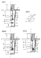
- Fig. 1
- is a fragmentary side, elevational and partly axial sectional view of a lower part of a container/dispenser assembly, prior to the first actuating stroke with an upper resilient detent ring abutting against the cylindrical neck of the drug container and still on its seat,
- Fig. 2
- is a plane view of one of the resilient detent rings provided with a radial cut aiding elasticity,
- Fig. 3
- is a view similar to Fig. 1 but after the first actuation stroke where the upper resilient decent ring has snapped out from its seat and rests against the lower one, which now acts as an end stop to the first half stroke of the piston/pump,
- Fig. 4
- is a view similar to Figs. 1 and 3, but after the second and last actuation stroke, where the lower detent ring is also snapped out from its seat allowing the second half stroke to be performed with the proper servo-assisted speed,
- Fig. 5
- is a view similar to Fig. 1 of a slightly modified embodiment comprising a housing/button and a slider provided with auxiliary stop elements,
- Fig. 6
- is a plane view of the bottom of the embodiment shown in Fig. 5,
- Fig. 7
- is a view similar to Fig. 3 of the embodiment shown in Fig. 5 showing the location of the parts at the end of the first actuating stroke, and
- Fig. 8
- is a view similar to Fig. 4 of the embodiment shown in Fig. 5 after the second and last actuation stroke.
- As clearly shown in Fig. 1, the container/dispenser for endonasal atomized administration substantially comprises a main body or
slider 1 provided with radially extending faces serving as grips and pressers for finger actuation and with an upwardly protruding tubular cylinder supporting the atomizing nozzle (not shown) on the top thereof. - From the lower part said
slider 1 protrudes downwardly forming acylindrical neck 2 within which a cup-shaped button/housing element 3 is axially slidable, thehousing 3 engaging with its bottom the lower end of astem 4 of a piston/pump 12 which can slide axially into aliquid drug container 5. - The
stem 4 of the piston/pump 12 has two different diameters, namely a larger upper one and a smaller lower one, and is provided on each of the two diameters with concave bottomcircular grooves detent rings - The bottom of the
upper groove 6 and therefore the central hole in the upper resilientdetent ring 8 both have a diameter which is larger than the corresponding one of thegroove 7 and thering 9, and also slightly larger than the diameter of the lower part of the stem of the piston/pump 12. - The two diameters of the
stem 4 are bridged by abevel 10 which allows better snapping out of the resilientdetent ring 8 and an easier assembling of the ring into thegroove 6 during the manufacturing process. - The two resilient
detent rings radial cut 11 as shown in Fig. 2. - The unit comprising the piston/
pump 12 and itsstem 4, provided with thegrooves detent rings edge 13 of thecontainer 5 constitute a servo-assisting device guaranteeing a safer and perfect atomization of the drug in two deliveries, each comprising one half of the available amount of drug. - The operation of the atomizer will be described hereinafter with particular reference to Figs. 1, 3 and 4.
- In the position shown in Fig. 1 the upper resilient
detent ring 8 abuts against thelower edge 13 of thecontainer 5. When the button/housing 3 is pressed in the direction indicated by the arrow for the first drug delivery, this pressure is transmitted to the piston/pump 12 engaging with the end of itsstem 4 the bottom of the button/housing 3. - In this state the movement of the piston/
pump 12 is opposed by the resilientdetent ring 8 abutting against theedge 13 of thecontainer 5. - In order to obtain the first dispension of the drug, it is necessary to exert a pressure strong enough to expand the resilient
detent ring 8 and thereby to snap it out from thegroove 6 so that the ring slides downwardly until it is stopped by the resilientdetent ring 9 still resting in itsgroove 7, thus allowing the piston/pump 12 to perform the first half of its movement into the container 5 - as shown in Fig. 3 -, the created pressure being dependent on the elasticity of the resilientdetent ring 8 and producing an accumulation of energy in the user's hand, which is instantly released when the resilientdetent ring 8 snaps out of thegroove 6. - To obtain the second delivery, i.e. the second half of the available amount, the same operation has to be repeated.
- The resilient
detent ring 9 exerts the same resistance as thering 8 in its first stage and requires again that enough energy is accumulated in the user's hand to snap it out of the groove/seat 7 as shown in fig. 4. - The instant release of the accumulated energy will again produce the best atomization not depending on the speed of depression exerted by the user on the
slider 1 and the button/housing 3. - Figs. 5, 6, 7 and 8 show a modification wherein the housing/
container 103 is provided with two stop-protrusions 114, and aprotruding neck 102 of theslider 101 is provided with twovertical slots 115, each comprising astop shoulder 116 as shown in Fig. 5 and 6. - All other parts and functions remain unchanged with respect to the basic embodiment.
- As shown in Fig. 7, at the end of the first stroke the operation of the housing/
container 103 and therefore of the piston/pump 12 is stopped by the abutting of the resilientdetent ring 9 against thering 8 and also by the detent action of theshoulders 116 against theprotrusions 114 of the housing/container 103. - To cause the second stroke it is necessary to turn the housing/container 103 - as indicated by the arrows in Fig. 6 and 7 - in order to remove the obstacle created by the abuttment of the
shoulder 116 against theprotrusion 114, and to then apply the pressure as previously described. - The modifications described herein improve the safety in the control of the first stroke and avoid any possibility of accidentally delivering the two doses within the same activation stroke.
- Another embodiment of the invention has the grooves/seats retaining the resilient detent rings formed on the inner wall of the button/
housing 3, according toclaim 6. - It is finally to be noted that within the scope ot the present invention the described device may also be designed as a one-step dispenser, said stem being provided with only one circular groove serving as a ring seat for only one resilient detent ring with a radial cut, said ring being provided on said seat for controlling the movement of the piston/pump for one-step dispension.
Claims (6)
- An atomizing dispenser for endonasal drug spray dispensing comprising:
a main body (1) comprising an inner cylindrical pump chamber (5) having an open end with a lower edge (13) and a bottom end provided with an opening, and a tubular part in fluid connection with said opening and fitted with an atomizing nozzle, said main body being provided with radially extending faces serving as grips and pressers;
a piston (12) slidable in said pump chamber (5), said piston being fitted with a stem (4),
said dispenser being characterized in that said stem is provided with at least one concave bottom circular groove (6) and in that one resilient detent ring (8) is disposed in each of said at least one groove (6), each of said rings having an outer diameter greater than said piston (12);
so that, when pressing said piston into said chamber, said lower edge (13) abuts against one ring (8) and it is necessary to exert enough pressure to make said ring (8) to expand and snap out from said groove (6) for having said piston (12) sliding in said chamber (5) for an activation stroke. - A dispenser according to claim 1, wherein said stem is provided with a least two grooves (6, 7) each containing one detent ring (8, 9), said stem having portions of different diameters, the diameters being shorter and shorter in direction from said piston toward said stem, and one groove is provided in each portion.
- A dispenser according to any of claims 2 to 4, wherein said stem is formed with two different diameters, with one concave bottom circular groove on each diameter.
- A dispenser according to claim 1, 2, or 3, wherein said body is fitted with a depending cylindrical skirt (2) surrounding said chamber, and said stem is fitted with a cylindrical cup shaped housing (3) formed for sliding in said skirt.
- A dispenser according to claim 4, wherein one of said housing and said skirt is fitted with at least one stop protrusion (114), and the other of said housing and said skirt is formed with at least one axial slot (115) comprising a stop shoulder (116), so that during an activation stroke, said stop protrusion slides in said slot until it reaches the stop shoulder, thus obliging the user to intentionally rotate the housing with respect to the body to disengage the protrusion from the shoulder before to perform a further activation stroke.
- An atomizing dispenser for endonasal drug spray dispensing comprising:
a main body (1) comprising an inner cylindrical pump chamber (5) having an open end with a tower edge (13) and a bottom end provided with an opening, and a tubular part in fluid connection with said opening and fitted with an atomizing nozzle, said main body being provided with radially extending faces serving as grips and pressers;
a piston (12) slidable in said pump chamber (5), said piston being fitted with a stem (4),
said body (1) being fitted with a depending cylindrical skirt (2) surrounding said chamber (5), and said stem (4) is fitted with a cylindrical cup shaped housing (3) formed for sliding in said skirt (2),
said dispenser being characterized in that the inner wall of said housing (3) is provided with at least one concave bottom circular groove (6) and in that one resilient detent ring (8) is disposed in each of said at lease one groove (6), each of said rings (8) having an inner diameter shorter than the outer diameter of said lower edge (13);
so that, when pressing said piston into said chamber, said lower edge (13) abuts against one ring (8) and it is necessary to exert enough pressure to make said ring (8) to contract and snap out from said groove (6) for having said piston (12) sliding in said chamber (5) for an activation stroke.
Applications Claiming Priority (3)
| Application Number | Priority Date | Filing Date | Title |
|---|---|---|---|
| ITGE910102A IT1253173B (en) | 1991-08-02 | 1991-08-02 | ENDONASAL CONTAINER-NEBULIZER WITH A SERVO-DISPENSING DEVICE INCORPORATED TO ENSURE THE EFFECTIVE ADMINISTRATION IN TWO TIMES. |
| ITGE91010 | 1991-08-02 | ||
| PCT/IT1992/000090 WO1993002804A1 (en) | 1991-08-02 | 1992-07-30 | Atomizing dispenser for endonasal drug spray administration |
Publications (2)
| Publication Number | Publication Date |
|---|---|
| EP0597023A1 EP0597023A1 (en) | 1994-05-18 |
| EP0597023B1 true EP0597023B1 (en) | 1995-12-06 |
Family
ID=11354111
Family Applications (1)
| Application Number | Title | Priority Date | Filing Date |
|---|---|---|---|
| EP92917580A Expired - Lifetime EP0597023B1 (en) | 1991-08-02 | 1992-07-30 | Atomizing dispenser for endonasal drug spray administration |
Country Status (5)
| Country | Link |
|---|---|
| US (1) | US5501373A (en) |
| EP (1) | EP0597023B1 (en) |
| DE (1) | DE69206621T2 (en) |
| IT (1) | IT1253173B (en) |
| WO (1) | WO1993002804A1 (en) |
Families Citing this family (8)
| Publication number | Priority date | Publication date | Assignee | Title |
|---|---|---|---|---|
| GB9311892D0 (en) * | 1993-06-09 | 1993-07-28 | Glaxo Wellcome Australia Ltd | Device |
| JP2930526B2 (en) * | 1994-05-31 | 1999-08-03 | 株式会社キートロン | Injector type atomizer |
| DE19723133A1 (en) * | 1997-06-03 | 1998-12-10 | Caideil M P Teoranta Tourmakea | Discharge device for media |
| DE19944211A1 (en) * | 1999-09-15 | 2001-03-22 | Pfeiffer Erich Gmbh & Co Kg | Device for the optionally atomized application of an in particular liquid medium |
| FR2817245B1 (en) * | 2000-11-30 | 2003-05-02 | Valois Sa | FLUID PRODUCT DISPENSING DEVICE |
| MXPA03011532A (en) * | 2001-06-15 | 2004-03-19 | Akzo Nobel Nv | Dispenser for administration of a pharmaceutical fluid. |
| GB0215270D0 (en) | 2002-07-02 | 2002-08-14 | Optinose As | Nasal devices |
| ES2871777T3 (en) | 2009-12-23 | 2021-11-02 | Becton Dickinson Co | Nasal single-dose medication delivery device |
Family Cites Families (13)
| Publication number | Priority date | Publication date | Assignee | Title |
|---|---|---|---|---|
| GB191655A (en) * | 1922-03-16 | 1923-01-18 | Joseph Marie Etienne Franc | Improvements in or relating to means for use in discharging or emptying containers and the like |
| US2474496A (en) * | 1947-06-26 | 1949-06-28 | Rayman Lawrence | Syringe |
| US2764981A (en) * | 1955-09-01 | 1956-10-02 | Norman D Helmer | Multiple dosage syringe |
| US2869541A (en) * | 1956-01-13 | 1959-01-20 | Norman D Helmer | Syringe structure |
| US3563240A (en) * | 1966-07-20 | 1971-02-16 | Jules Silver | Dual unit syringe |
| GB1225495A (en) * | 1967-06-15 | 1971-03-17 | ||
| DE7916475U1 (en) * | 1979-06-08 | 1979-10-18 | Hoechst Ag, 6000 Frankfurt | Spray applicator |
| US4475905A (en) * | 1982-09-30 | 1984-10-09 | Himmelstrup Anders B | Injection device |
| US5257726A (en) * | 1985-08-14 | 1993-11-02 | Ing. Erich Pfeiffer Gmbh & Co. Kg | Dispenser for flowable media |
| DE3734306A1 (en) * | 1987-10-10 | 1989-04-27 | Pfeiffer Erich Gmbh & Co Kg | DISCHARGE DEVICE FOR FLOWABLE MEDIA |
| DE3810262A1 (en) * | 1988-03-25 | 1989-10-12 | Henning Berlin Gmbh | DEVICE FOR THE DOSED ADMINISTRATION OF A LIQUID MEDICINAL PRODUCT |
| US4923448A (en) * | 1988-12-06 | 1990-05-08 | Mark Anderson | Syringe with spray nozzle tip |
| IT1244803B (en) * | 1990-11-21 | 1994-09-05 | Promo Pack S A | SINGLE-DOSE DISPENSER-SPRAYER FOR ENDONASAL ADMINISTRATION OF LIQUID MEDICATIONS. |
-
1991
- 1991-08-02 IT ITGE910102A patent/IT1253173B/en active IP Right Grant
-
1992
- 1992-07-30 WO PCT/IT1992/000090 patent/WO1993002804A1/en active IP Right Grant
- 1992-07-30 EP EP92917580A patent/EP0597023B1/en not_active Expired - Lifetime
- 1992-07-30 US US08/190,112 patent/US5501373A/en not_active Expired - Lifetime
- 1992-07-30 DE DE69206621T patent/DE69206621T2/en not_active Expired - Fee Related
Also Published As
| Publication number | Publication date |
|---|---|
| US5501373A (en) | 1996-03-26 |
| EP0597023A1 (en) | 1994-05-18 |
| WO1993002804A1 (en) | 1993-02-18 |
| DE69206621D1 (en) | 1996-01-18 |
| ITGE910102A0 (en) | 1991-08-02 |
| ITGE910102A1 (en) | 1993-02-02 |
| DE69206621T2 (en) | 1996-08-01 |
| IT1253173B (en) | 1995-07-10 |
Similar Documents
| Publication | Publication Date | Title |
|---|---|---|
| EP0625075B1 (en) | Spray pump package employing multiple orifices for dispensing liquid in different spray patterns with automatically adjusted optimized pump stroke for each pattern | |
| US6321942B1 (en) | Discharge device for flowable media using a thrust piston pump | |
| EP1214985B1 (en) | Device of miniaturised construction for producing high pressure in a fluid to be atomised | |
| US8734392B2 (en) | Dosing device having a pumping device | |
| US6364166B1 (en) | Dispenser with manually operable discharge device | |
| US6964381B2 (en) | Atomization device with lateral actuation | |
| EP0918570B1 (en) | Dispensing device | |
| KR101526843B1 (en) | A dispensing device | |
| EP1101535B1 (en) | Dosage control for dispenser with child-resistant feature | |
| US8096450B2 (en) | Lateral actuation spray device | |
| CA2256008A1 (en) | Fluid dispenser | |
| EP0597023B1 (en) | Atomizing dispenser for endonasal drug spray administration | |
| JP2001520580A (en) | Fluid spray device such as a double dispenser | |
| WO1992020455A1 (en) | Mechanical self-actuated system for medicament atomizing dispensers | |
| US20230277785A1 (en) | Device for dispensing a fluid product | |
| US20220409833A1 (en) | Device for dispensing a fluid product | |
| US7237549B2 (en) | Device for distributing a fluid of the single dose or half dose type | |
| WO2005000477A1 (en) | Dispenser | |
| US20230398561A1 (en) | Device for dispensing a fluid product | |
| MX2007007166A (en) | Fluid or pasty product dispensing device. | |
| US4951840A (en) | Pump dispenser for dispensing accurate small quantities of a fluid substance | |
| US6321952B1 (en) | Sprayer actuating device | |
| JP3313428B2 (en) | Spray dispenser for spray administration of intranasal drugs | |
| GB2337040A (en) | Dispensing apparatus | |
| EP4201457A1 (en) | Atomizing means |
Legal Events
| Date | Code | Title | Description |
|---|---|---|---|
| PUAI | Public reference made under article 153(3) epc to a published international application that has entered the european phase |
Free format text: ORIGINAL CODE: 0009012 |
|
| 17P | Request for examination filed |
Effective date: 19940228 |
|
| AK | Designated contracting states |
Kind code of ref document: A1 Designated state(s): DE FR GB |
|
| 17Q | First examination report despatched |
Effective date: 19940525 |
|
| GRAA | (expected) grant |
Free format text: ORIGINAL CODE: 0009210 |
|
| AK | Designated contracting states |
Kind code of ref document: B1 Designated state(s): DE FR GB |
|
| RIN1 | Information on inventor provided before grant (corrected) |
Inventor name: GALLI, ROSARIA |
|
| REF | Corresponds to: |
Ref document number: 69206621 Country of ref document: DE Date of ref document: 19960118 |
|
| ET | Fr: translation filed | ||
| PLBE | No opposition filed within time limit |
Free format text: ORIGINAL CODE: 0009261 |
|
| STAA | Information on the status of an ep patent application or granted ep patent |
Free format text: STATUS: NO OPPOSITION FILED WITHIN TIME LIMIT |
|
| 26N | No opposition filed | ||
| REG | Reference to a national code |
Ref country code: GB Ref legal event code: IF02 |
|
| PGFP | Annual fee paid to national office [announced via postgrant information from national office to epo] |
Ref country code: GB Payment date: 20050727 Year of fee payment: 14 Ref country code: FR Payment date: 20050727 Year of fee payment: 14 |
|
| PGFP | Annual fee paid to national office [announced via postgrant information from national office to epo] |
Ref country code: DE Payment date: 20050831 Year of fee payment: 14 |
|
| PG25 | Lapsed in a contracting state [announced via postgrant information from national office to epo] |
Ref country code: GB Free format text: LAPSE BECAUSE OF NON-PAYMENT OF DUE FEES Effective date: 20060730 |
|
| PG25 | Lapsed in a contracting state [announced via postgrant information from national office to epo] |
Ref country code: DE Free format text: LAPSE BECAUSE OF NON-PAYMENT OF DUE FEES Effective date: 20070201 |
|
| GBPC | Gb: european patent ceased through non-payment of renewal fee |
Effective date: 20060730 |
|
| REG | Reference to a national code |
Ref country code: FR Ref legal event code: ST Effective date: 20070330 |
|
| PG25 | Lapsed in a contracting state [announced via postgrant information from national office to epo] |
Ref country code: FR Free format text: LAPSE BECAUSE OF NON-PAYMENT OF DUE FEES Effective date: 20060731 |