EP0597213B1 - Suture sleeve with lead locking device - Google Patents
Suture sleeve with lead locking device Download PDFInfo
- Publication number
- EP0597213B1 EP0597213B1 EP93115017A EP93115017A EP0597213B1 EP 0597213 B1 EP0597213 B1 EP 0597213B1 EP 93115017 A EP93115017 A EP 93115017A EP 93115017 A EP93115017 A EP 93115017A EP 0597213 B1 EP0597213 B1 EP 0597213B1
- Authority
- EP
- European Patent Office
- Prior art keywords
- sleeve
- lock member
- throughbore
- sleeve body
- lead
- Prior art date
- Legal status (The legal status is an assumption and is not a legal conclusion. Google has not performed a legal analysis and makes no representation as to the accuracy of the status listed.)
- Expired - Lifetime
Links
Images


Classifications
-
- A—HUMAN NECESSITIES
- A61—MEDICAL OR VETERINARY SCIENCE; HYGIENE
- A61N—ELECTROTHERAPY; MAGNETOTHERAPY; RADIATION THERAPY; ULTRASOUND THERAPY
- A61N1/00—Electrotherapy; Circuits therefor
- A61N1/02—Details
- A61N1/04—Electrodes
- A61N1/05—Electrodes for implantation or insertion into the body, e.g. heart electrode
- A61N1/056—Transvascular endocardial electrode systems
- A61N1/057—Anchoring means; Means for fixing the head inside the heart
-
- A—HUMAN NECESSITIES
- A61—MEDICAL OR VETERINARY SCIENCE; HYGIENE
- A61M—DEVICES FOR INTRODUCING MEDIA INTO, OR ONTO, THE BODY; DEVICES FOR TRANSDUCING BODY MEDIA OR FOR TAKING MEDIA FROM THE BODY; DEVICES FOR PRODUCING OR ENDING SLEEP OR STUPOR
- A61M25/00—Catheters; Hollow probes
- A61M2025/0098—Catheters; Hollow probes having a strain relief at the proximal end, e.g. sleeve
-
- A—HUMAN NECESSITIES
- A61—MEDICAL OR VETERINARY SCIENCE; HYGIENE
- A61N—ELECTROTHERAPY; MAGNETOTHERAPY; RADIATION THERAPY; ULTRASOUND THERAPY
- A61N1/00—Electrotherapy; Circuits therefor
- A61N1/02—Details
- A61N1/04—Electrodes
- A61N1/05—Electrodes for implantation or insertion into the body, e.g. heart electrode
- A61N1/056—Transvascular endocardial electrode systems
- A61N1/057—Anchoring means; Means for fixing the head inside the heart
- A61N2001/0582—Suture sleeves
Definitions
- US-A-3,329,391 discloses a surgical pinch valve which includes a sleeve body having a throughbore to receive a fluid tube and a perpendicular channel intersecting the throughbore, a push button lock member movably disposed within the channel to receive the tube, the lock member being movable to pinch the tube to various degrees, and detents disposed on a side of the button lock member and in a side of the sleeve body throughbore to hold the lock member in the selected pinching position.
Description
Claims (7)
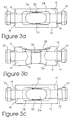
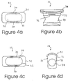
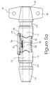
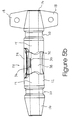
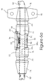
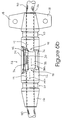
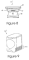
- A suture sleeve adapted to secure a flexible, elongated structure (40) to a patient's body tissue, comprisinga sleeve body (12) having a longitudinal throughbore (14) to receive said elongated structure (40) and a perpendicular channel (26) intersecting the throughbore (14),a push button lock member (22) movably disposed within said channel (26) and having a throughbore (38) to receive the elongated structure (40), the lock member (22) being movable between a first position in which its throughbore (38) is coaxial with the sleeve body throughbore (14), and a second position in which its throughbore (38) is not coaxial with the sleeve body throughbore (14) and the lock member (22) substantially resists movement of the elongated structure (40) relative to the sleeve body (12), anda longitudinal detent (36) disposed on a side of the button lock member (22) and a longitudinal groove (30) formed in a side of said sleeve body throughbore (14), said groove (30) being adapted to receive said detent (36) when said lock member (22) is in its second position such that said lock member (22) is held in said second position.
- The sleeve of claim 1, further comprisingfirst and second collar pieces (16) each affixed to one end of said sleeve body (12) and having a throughbore which is dimensioned to receive said elongated structure (40) and is in substantial coaxial alignment with said sleeve body throughbore (14),each collar piece (16) being made of a resilient material and having a length dimension sufficient to reduce substantial bending of the elongated structure (40) in the region of the sleeve body (12).
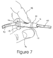
- The sleeve of claim 2, wherein one of said collar pieces (16) has a suture receiving groove (20) formed therein.
- The sleeve of claim 3 or 4, wherein one of said collar pieces (16) comprises a suture tab (18) projecting therefrom.
- The sleeve of any one of claims 1 to 4, wherein said lock member throughbore (38) has textured side walls (50) for enhancing the frictional resistance against movement of said elongated structure (40) through said suture sleeve (10) when said lock member (22) is in its second position.
- The sleeve of any one of claims 1 to 5, wherein a top portion (34) of said lock member (22) is flared and a shallow recess (28) is formed in said sleeve body (12) adapted to receive said lock member top portion (34) and prohibit movement of said lock member (22) in one direction when said lock member (22) is in its second position.
- The sleeve of claim 6, wherein said flared top portion (34) of said lock member (22) is flush with a outer surface of said sleeve body (12) when said lock member (22) is in its second position.
Applications Claiming Priority (2)
| Application Number | Priority Date | Filing Date | Title |
|---|---|---|---|
| US07/971,017 US5273053A (en) | 1992-11-02 | 1992-11-02 | Suture sleeve with lead locking device |
| US971017 | 1992-11-02 |
Publications (2)
| Publication Number | Publication Date |
|---|---|
| EP0597213A1 EP0597213A1 (en) | 1994-05-18 |
| EP0597213B1 true EP0597213B1 (en) | 1999-03-24 |
Family
ID=25517823
Family Applications (1)
| Application Number | Title | Priority Date | Filing Date |
|---|---|---|---|
| EP93115017A Expired - Lifetime EP0597213B1 (en) | 1992-11-02 | 1993-09-17 | Suture sleeve with lead locking device |
Country Status (6)
| Country | Link |
|---|---|
| US (1) | US5273053A (en) |
| EP (1) | EP0597213B1 (en) |
| JP (1) | JP2523445B2 (en) |
| AU (1) | AU655373B2 (en) |
| CA (1) | CA2106332C (en) |
| DE (1) | DE69324102T2 (en) |
Cited By (6)
| Publication number | Priority date | Publication date | Assignee | Title |
|---|---|---|---|---|
| US7082337B2 (en) | 2003-12-18 | 2006-07-25 | Medtronic, Inc. | Suture sleeve |
| US7806873B2 (en) | 2006-07-13 | 2010-10-05 | Venetec International, Inc. | Intravenous securement device with adhesively interconnected anchoring component and permeable adhesive strip |
| US7879013B2 (en) | 2005-12-21 | 2011-02-01 | Venetec International, Inc. | Intravenous catheter anchoring device |
| US8052648B2 (en) | 2005-12-21 | 2011-11-08 | Venetec International, Inc. | Intravenous catheter anchoring device |
| US8295948B2 (en) | 2009-07-21 | 2012-10-23 | Boston Scientific Neuromodulation Corporation | Tubular lead anchor and methods and devices using the anchor |
| US9585654B2 (en) | 2012-05-01 | 2017-03-07 | Dean & Webb, LLC | Segmentally rigid suture and suturing technique |
Families Citing this family (135)
| Publication number | Priority date | Publication date | Assignee | Title |
|---|---|---|---|---|
| US5476493A (en) * | 1993-05-19 | 1995-12-19 | Pacesetter, Inc. | Implantable lead having self-locking suture sleeve |
| US5376108A (en) * | 1993-05-20 | 1994-12-27 | Telectronics Pacing Systems, Inc. | Electrode lead anchoring apparatus and method employing dual suture collars |
| US5628778A (en) * | 1994-11-21 | 1997-05-13 | Medtronic Inc. | Single pass medical electrical lead |
| US5584874A (en) * | 1995-04-28 | 1996-12-17 | Medtronic, Inc. | Medical electrical lead having improved anchoring sleeve |
| US5876429A (en) * | 1995-06-07 | 1999-03-02 | Intermedics, Inc. | Methods and devices for in vivo repair of cardiac stimulator leads |
| US5824032A (en) * | 1996-08-09 | 1998-10-20 | Medtronic Inc. | Medical electrical lead featuring a one piece lead anchoring sleeve with wrap-around locking arms |
| US5735891A (en) * | 1996-12-02 | 1998-04-07 | Sulzer Intermedics Inc. | Self-clamping anchoring sleeve |
| US5746722A (en) * | 1997-02-05 | 1998-05-05 | Medtronic, Inc. | Suture sleeve with circumferential lead locking device |
| US5938596A (en) * | 1997-03-17 | 1999-08-17 | Medtronic, Inc. | Medical electrical lead |
| US5843146A (en) * | 1997-04-30 | 1998-12-01 | Medtronic Incorporated | Adjustable medical lead anchor |
| US6024764A (en) * | 1997-08-19 | 2000-02-15 | Intermedics, Inc. | Apparatus for imparting physician-determined shapes to implantable tubular devices |
| US5908447A (en) * | 1998-02-06 | 1999-06-01 | Intermedics Inc. | Breakaway structure for body implantable medical device |
| US6002969A (en) * | 1998-08-05 | 1999-12-14 | Intermedics Inc. | Cardiac lead with shape-memory structure |
| US6549812B1 (en) | 1999-11-29 | 2003-04-15 | Medtronic, Inc. | Medical electrical lead having bending stiffness which increase in the distal direction |
| US6556873B1 (en) | 1999-11-29 | 2003-04-29 | Medtronic, Inc. | Medical electrical lead having variable bending stiffness |
| US7993368B2 (en) | 2003-03-13 | 2011-08-09 | C.R. Bard, Inc. | Suture clips, delivery devices and methods |
| EP1261282B1 (en) | 2000-03-03 | 2013-09-25 | C. R. Bard, Inc. | Endoscopic tissue apposition device with multiple suction ports |
| ES2435094T3 (en) | 2000-05-19 | 2013-12-18 | C.R. Bard, Inc. | Device and method of tissue capture and suturing |
| US8105351B2 (en) | 2001-05-18 | 2012-01-31 | C.R. Bard, Inc. | Method of promoting tissue adhesion |
| US7031774B1 (en) | 2000-10-11 | 2006-04-18 | Pacesetter, Inc. | Switch for electrode selections in Single-pass Atrial/Ventricular leads |
| US6901287B2 (en) | 2001-02-09 | 2005-05-31 | Medtronic, Inc. | Implantable therapy delivery element adjustable anchor |
| US7463934B2 (en) * | 2002-04-12 | 2008-12-09 | Medtronic, Inc. | Implantable medical device with captivation fixation |
| US6997919B2 (en) * | 2002-04-23 | 2006-02-14 | Medtronic, Inc. | Implantable medical connector for medical tubing with anchoring features |
| WO2004021873A2 (en) | 2002-09-06 | 2004-03-18 | C.R. Bard, Inc. | Integrated endoscope and accessory treatment device |
| US20040059403A1 (en) * | 2002-09-24 | 2004-03-25 | Geriche, Inc. | Suture sleeve |
| US6939240B2 (en) * | 2003-01-23 | 2005-09-06 | Richard A. Daley | Golf putting device |
| BRPI0410376B1 (en) | 2003-05-16 | 2016-06-14 | Bard Inc C R | endoscopic suture system and single intubation |
| US7316694B2 (en) * | 2003-11-26 | 2008-01-08 | Karl Reinitz | Surgical suturing apparatus |
| US7725196B2 (en) | 2004-05-04 | 2010-05-25 | The Cleveland Clinic Foundation | Corpus callosum neuromodulation assembly |
| US7184841B1 (en) * | 2004-08-19 | 2007-02-27 | Cardiac Pacemakers, Inc. | Pacing lead stabilizer |
| US20060127158A1 (en) * | 2004-10-21 | 2006-06-15 | Medtronic, Inc. | Implantable electrical lead retention system and method |
| US7853321B2 (en) * | 2005-03-14 | 2010-12-14 | Boston Scientific Neuromodulation Corporation | Stimulation of a stimulation site within the neck or head |
| US8423155B1 (en) | 2005-03-14 | 2013-04-16 | Boston Scientific Neuromodulation Corporation | Methods and systems for facilitating stimulation of one or more stimulation sites |
| US7848803B1 (en) * | 2005-03-14 | 2010-12-07 | Boston Scientific Neuromodulation Corporation | Methods and systems for facilitating stimulation of one or more stimulation sites |
| WO2006116454A2 (en) * | 2005-04-26 | 2006-11-02 | Cook Vascular Incorporated | Suture collar |
| US7448653B2 (en) | 2005-06-10 | 2008-11-11 | Value Plastics, Inc. | Female connector for releasable coupling with a male connector defining a fluid conduit |
| WO2007024164A1 (en) * | 2005-08-24 | 2007-03-01 | St. Jude Medical Ab | Suture sleeve with lead locking device |
| US7831313B2 (en) * | 2005-08-26 | 2010-11-09 | Boston Scientific Neuromodulation Corporation | Lead anchor for implantable stimulation devices and methods of manufacture and use |
| US9642987B2 (en) | 2005-08-31 | 2017-05-09 | C.R. Bard, Inc. | Anchoring system for a catheter |
| WO2007059386A2 (en) * | 2005-11-10 | 2007-05-24 | Medtronic, Inc. | Intravascular medical device |
| US7806139B2 (en) | 2006-01-20 | 2010-10-05 | Value Plastics, Inc. | Fluid conduit coupling assembly having male and female couplers with integral valves |
| US7616992B2 (en) * | 2006-01-30 | 2009-11-10 | Medtronic, Inc. | Intravascular medical device |
| US7519424B2 (en) * | 2006-01-30 | 2009-04-14 | Medtronic, Inc. | Intravascular medical device |
| US7627376B2 (en) * | 2006-01-30 | 2009-12-01 | Medtronic, Inc. | Intravascular medical device |
| US9005220B2 (en) | 2006-04-04 | 2015-04-14 | C.R. Bard, Inc. | Suturing devices and methods with energy emitting elements |
| US8244379B2 (en) * | 2006-04-26 | 2012-08-14 | Medtronic, Inc. | Pericardium fixation concepts of epicardium pacing leads and tools |
| US7787960B2 (en) * | 2007-02-15 | 2010-08-31 | Boston Scientific Neuromodulation Corporation | Lead anchoring assembly |
| US9072897B2 (en) | 2007-03-09 | 2015-07-07 | Mainstay Medical Limited | Systems and methods for restoring muscle function to the lumbar spine |
| US10925637B2 (en) | 2010-03-11 | 2021-02-23 | Mainstay Medical Limited | Methods of implanting electrode leads for use with implantable neuromuscular electrical stimulator |
| US11331488B2 (en) | 2007-03-09 | 2022-05-17 | Mainstay Medical Limited | Systems and methods for enhancing function of spine stabilization muscles associated with a spine surgery intervention |
| US11679262B2 (en) | 2007-03-09 | 2023-06-20 | Mainstay Medical Limited | Systems and methods for restoring muscle function to the lumbar spine |
| US11679261B2 (en) | 2007-03-09 | 2023-06-20 | Mainstay Medical Limited | Systems and methods for enhancing function of spine stabilization muscles associated with a spine surgery intervention |
| US8428728B2 (en) | 2007-03-09 | 2013-04-23 | Mainstay Medical Limited | Muscle stimulator |
| US20090112301A1 (en) * | 2007-10-25 | 2009-04-30 | Kowalczyk James M | Strain Relief System For Spinal Cord Stimulation Lead |
| US8249719B2 (en) * | 2007-11-09 | 2012-08-21 | Cardiac Pacemakers, Inc. | Lead stabilizer with retention features |
| US8249720B2 (en) * | 2007-11-09 | 2012-08-21 | Cardiac Pacemakers, Inc. | Compression member suture sleeve |
| USD654573S1 (en) | 2007-11-19 | 2012-02-21 | Value Plastics, Inc. | Female quick connect fitting |
| EP2271393B1 (en) * | 2008-03-28 | 2015-06-17 | St. Jude Medical AB | Suture sleeve |
| US8235426B2 (en) | 2008-07-03 | 2012-08-07 | Nordson Corporation | Latch assembly for joining two conduits |
| US8140172B1 (en) * | 2008-07-11 | 2012-03-20 | Advanced Neuromodulation Systems, Inc. | Implantable anchor with locking arm |
| WO2010036227A1 (en) | 2008-09-29 | 2010-04-01 | C R . Bard, Inc . | Endoscopic suturing device |
| WO2010048052A1 (en) | 2008-10-22 | 2010-04-29 | Boston Scientific Scimed, Inc. | Shape memory tubular stent with grooves |
| US9887470B2 (en) | 2009-04-27 | 2018-02-06 | Boston Scienific Neuromodulation Corporation | Torque lock anchor and methods and devices using the anchor |
| US9352147B2 (en) | 2009-04-27 | 2016-05-31 | Boston Scientific Neuromodulation Corporation | Torque lock anchor and methods and devices using the anchor |
| US8394067B2 (en) | 2009-05-21 | 2013-03-12 | C.R. Bard, Inc. | Medical device securement system |
| USD655393S1 (en) | 2009-06-23 | 2012-03-06 | Value Plastics, Inc. | Multi-port valve |
| US8229573B2 (en) | 2009-07-21 | 2012-07-24 | Boston Scientific Neuromodulation Corporation | Spring passive lead anchor and methods and devices using the anchor |
| USD783815S1 (en) | 2009-12-09 | 2017-04-11 | General Electric Company | Male dual lumen bayonet connector |
| US9388929B2 (en) | 2009-12-09 | 2016-07-12 | Nordson Corporation | Male bayonet connector |
| USD649240S1 (en) | 2009-12-09 | 2011-11-22 | Value Plastics, Inc. | Male dual lumen bayonet connector |
| US10711930B2 (en) | 2009-12-09 | 2020-07-14 | Nordson Corporation | Releasable connection assembly |
| USD650478S1 (en) | 2009-12-23 | 2011-12-13 | Value Plastics, Inc. | Female dual lumen connector |
| WO2011079225A1 (en) | 2009-12-23 | 2011-06-30 | Value Plastics, Inc. | Fluid connector latches with profile lead-ins |
| WO2011079228A1 (en) | 2009-12-23 | 2011-06-30 | Value Plastics, Inc. | Button latch with integrally molded cantilever springs |
| CA2792529C (en) | 2010-03-11 | 2018-06-05 | Mainstay Medical, Inc. | Modular stimulator for treatment of back pain, implantable rf ablation system and methods of use |
| US8761902B2 (en) * | 2010-03-11 | 2014-06-24 | Advanced Neuromodulation Systems, Inc. | Implantable anchor for medical stimulation leads |
| US9999763B2 (en) | 2012-06-13 | 2018-06-19 | Mainstay Medical Limited | Apparatus and methods for anchoring electrode leads adjacent to nervous tissue |
| US9950159B2 (en) | 2013-10-23 | 2018-04-24 | Mainstay Medical Limited | Systems and methods for restoring muscle function to the lumbar spine and kits for implanting the same |
| US11684774B2 (en) | 2010-03-11 | 2023-06-27 | Mainstay Medical Limited | Electrical stimulator for treatment of back pain and methods of use |
| US11786725B2 (en) | 2012-06-13 | 2023-10-17 | Mainstay Medical Limited | Systems and methods for restoring muscle function to the lumbar spine and kits for implanting the same |
| US8494652B2 (en) | 2010-08-09 | 2013-07-23 | Advanced Neuromodulation Systems, Inc. | Implantable medical anchor |
| US8805519B2 (en) | 2010-09-30 | 2014-08-12 | Nevro Corporation | Systems and methods for detecting intrathecal penetration |
| US8965482B2 (en) | 2010-09-30 | 2015-02-24 | Nevro Corporation | Systems and methods for positioning implanted devices in a patient |
| US9550045B2 (en) | 2011-01-28 | 2017-01-24 | Medtronic, Inc. | Repositionable therapy delivery element anchor |
| USD652511S1 (en) | 2011-02-11 | 2012-01-17 | Value Plastics, Inc. | Female body of connector for fluid tubing |
| USD652510S1 (en) | 2011-02-11 | 2012-01-17 | Value Plastics, Inc. | Connector for fluid tubing |
| USD663022S1 (en) | 2011-02-11 | 2012-07-03 | Nordson Corporation | Male body of connector for fluid tubing |
| US8437846B2 (en) | 2011-03-11 | 2013-05-07 | Greatbatch Ltd. | Pre-sutured anchor for implantable leads |
| US8676341B2 (en) | 2011-06-21 | 2014-03-18 | Greatbatch Ltd. | Multi durometer reinforced suture sleeve |
| US8688232B2 (en) | 2011-06-21 | 2014-04-01 | Greatbatch Ltd. | Multi-durometer reinforced suture sleeve |
| USD698440S1 (en) | 2011-07-29 | 2014-01-28 | Nordson Corporation | Connector for fluid tubing |
| USD699840S1 (en) | 2011-07-29 | 2014-02-18 | Nordson Corporation | Male body of connector for fluid tubing |
| USD699841S1 (en) | 2011-07-29 | 2014-02-18 | Nordson Corporation | Female body of connector for fluid tubing |
| US20130158640A1 (en) * | 2011-12-19 | 2013-06-20 | Brian D. Soltis | Lead anchoring system with limited movement of anchoring device along lead |
| USD709612S1 (en) | 2011-12-23 | 2014-07-22 | Nordson Corporation | Female dual lumen connector |
| AU2013211937B2 (en) * | 2012-01-25 | 2016-07-28 | Nevro Corporation | Lead anchors and associated systems and methods |
| US10195419B2 (en) * | 2012-06-13 | 2019-02-05 | Mainstay Medical Limited | Electrode leads for use with implantable neuromuscular electrical stimulator |
| US9186501B2 (en) | 2012-06-13 | 2015-11-17 | Mainstay Medical Limited | Systems and methods for implanting electrode leads for use with implantable neuromuscular electrical stimulator |
| JP6085682B2 (en) | 2012-10-29 | 2017-02-22 | カーディアック ペースメイカーズ, インコーポレイテッド | Suture sleeve having an outer surface with fracture resistance |
| US9486622B2 (en) | 2012-11-08 | 2016-11-08 | Cardiac Pacemakers, Inc. | Fixation and strain relief element for temporary therapy delivery device |
| US20140330287A1 (en) | 2013-05-06 | 2014-11-06 | Medtronic, Inc. | Devices and techniques for anchoring an implantable medical device |
| US10532203B2 (en) | 2013-05-06 | 2020-01-14 | Medtronic, Inc. | Substernal electrical stimulation system |
| US9717923B2 (en) | 2013-05-06 | 2017-08-01 | Medtronic, Inc. | Implantable medical device system having implantable cardioverter-defibrillator (ICD) system and substernal leadless pacing device |
| US10471267B2 (en) | 2013-05-06 | 2019-11-12 | Medtronic, Inc. | Implantable cardioverter-defibrillator (ICD) system including substernal lead |
| US10556117B2 (en) | 2013-05-06 | 2020-02-11 | Medtronic, Inc. | Implantable cardioverter-defibrillator (ICD) system including substernal pacing lead |
| US9265935B2 (en) | 2013-06-28 | 2016-02-23 | Nevro Corporation | Neurological stimulation lead anchors and associated systems and methods |
| EP3030310A1 (en) * | 2013-08-07 | 2016-06-15 | Boston Scientific Neuromodulation Corporation | Systems and methods for making and using lead anchors for leads of electrical stimulation systems |
| US9216563B2 (en) | 2013-08-19 | 2015-12-22 | Boston Scientific Neuromodulation Corporation | Lead anchor with adhesive and systems and methods using the lead anchor |
| US9517334B2 (en) | 2013-08-19 | 2016-12-13 | Boston Scientific Neuromodulation Corporation | Lead anchors and systems and methods employing the lead anchors |
| US10434307B2 (en) | 2013-10-15 | 2019-10-08 | Medtronic, Inc. | Methods and devices for subcutaneous lead implantation |
| US9415212B2 (en) | 2014-02-28 | 2016-08-16 | Boston Scientific Neuromodulation Corporation | Side loading lead anchor and methods of making and using thereof |
| US9987482B2 (en) | 2014-05-27 | 2018-06-05 | Boston Scientific Neuromodulation Corporation | Systems and methods for making and using reversible mechanical lead anchors for electrical stimulation systems |
| US10328268B2 (en) | 2014-09-04 | 2019-06-25 | AtaCor Medical, Inc. | Cardiac pacing |
| US9636505B2 (en) | 2014-11-24 | 2017-05-02 | AtaCor Medical, Inc. | Cardiac pacing sensing and control |
| US10743960B2 (en) | 2014-09-04 | 2020-08-18 | AtaCor Medical, Inc. | Cardiac arrhythmia treatment devices and delivery |
| EP3188791A4 (en) | 2014-09-04 | 2018-03-28 | Atacor Medical, Inc. | Cardiac pacing lead delivery system |
| US10471268B2 (en) | 2014-10-16 | 2019-11-12 | Mainstay Medical Limited | Systems and methods for monitoring muscle rehabilitation |
| US9636512B2 (en) | 2014-11-05 | 2017-05-02 | Medtronic, Inc. | Implantable cardioverter-defibrillator (ICD) system having multiple common polarity extravascular defibrillation electrodes |
| US11097109B2 (en) | 2014-11-24 | 2021-08-24 | AtaCor Medical, Inc. | Cardiac pacing sensing and control |
| WO2016130769A1 (en) * | 2015-02-13 | 2016-08-18 | Gi Dynamics, Inc. | Devices and methods for placing a gastrointestinal device |
| WO2016187473A1 (en) | 2015-05-20 | 2016-11-24 | Cardiac Pacemakers, Inc. | Fully integrated lead stabilizer for medical electrical leads and methods of attachment |
| US9636498B2 (en) | 2015-08-03 | 2017-05-02 | Boston Scientific Neuromodulation Corporation | Lead anchor with a wedge and systems using the lead anchor |
| WO2017151438A1 (en) | 2016-02-29 | 2017-09-08 | Boston Scientific Neuromodulation Corporation | Lead anchor for an electrical stimulation system |
| EP3429679B1 (en) | 2016-05-17 | 2022-11-23 | Boston Scientific Neuromodulation Corporation | Systems for anchoring a lead for neurostimulation of a target anatomy |
| EP3463121B1 (en) * | 2016-05-25 | 2021-01-13 | Nalu Medical, Inc. | Systems for insertion of implantable devices |
| US10327810B2 (en) | 2016-07-05 | 2019-06-25 | Mainstay Medical Limited | Systems and methods for enhanced implantation of electrode leads between tissue layers |
| USD838366S1 (en) | 2016-10-31 | 2019-01-15 | Nordson Corporation | Blood pressure connector |
| US10709886B2 (en) | 2017-02-28 | 2020-07-14 | Boston Scientific Neuromodulation Corporation | Electrical stimulation leads and systems with elongate anchoring elements and methods of making and using |
| US10980999B2 (en) | 2017-03-09 | 2021-04-20 | Nevro Corp. | Paddle leads and delivery tools, and associated systems and methods |
| US10835739B2 (en) | 2017-03-24 | 2020-11-17 | Boston Scientific Neuromodulation Corporation | Electrical stimulation leads and systems with elongate anchoring elements and methods of making and using |
| US10857351B2 (en) | 2017-04-28 | 2020-12-08 | Boston Scientific Neuromodulation Corporation | Lead anchors for electrical stimulation leads and systems and methods of making and using |
| EP3758793A4 (en) | 2018-03-29 | 2021-12-08 | Nevro Corp. | Leads having sidewall openings, and associated systems and methods |
| GB2582584B (en) * | 2019-03-26 | 2022-01-12 | Cook Medical Technologies Llc | Medical device holding and delivery assembly and kit therefor |
| US20200398044A1 (en) | 2019-05-29 | 2020-12-24 | AtaCor Medical, Inc. | Implantable electrical leads and electrodes |
| US11666771B2 (en) | 2020-05-29 | 2023-06-06 | AtaCor Medical, Inc. | Implantable electrical leads and associated delivery systems |
Family Cites Families (16)
| Publication number | Priority date | Publication date | Assignee | Title |
|---|---|---|---|---|
| US3176690A (en) * | 1961-05-26 | 1965-04-06 | Doubler Peter B H | Catheter having integral, polymeric flanges |
| US3329391A (en) * | 1964-09-28 | 1967-07-04 | William V Deane | Surgical pinch valve |
| US4276882A (en) * | 1979-05-18 | 1981-07-07 | Medtronic, Inc. | Lead anchoring device |
| US4287891A (en) * | 1979-08-31 | 1981-09-08 | Peters Joseph L | Securing device for surgical tubes |
| US4516584A (en) * | 1983-01-07 | 1985-05-14 | Cordis Corporation | Suture collar |
| DE3300723A1 (en) * | 1983-01-11 | 1984-07-12 | Siemens AG, 1000 Berlin und 8000 München | Fixing clamp for a pacemaker electrode |
| DE3474514D1 (en) * | 1983-12-27 | 1988-11-17 | Pfister Lehmann Alfred | Closure at a ureteral catheter |
| US4553961A (en) * | 1984-04-18 | 1985-11-19 | Cordis Corporation | Suture sleeve with structure for enhancing pacing lead gripping |
| US4632670A (en) * | 1985-04-04 | 1986-12-30 | Argon Medical Corp. | Suture tab |
| US5129405A (en) * | 1985-09-18 | 1992-07-14 | Telectronics N.V. | Vein suture collar |
| US4672979A (en) * | 1986-01-30 | 1987-06-16 | Cordis Corporation | Suture sleeve assembly |
| US4860750A (en) * | 1986-04-17 | 1989-08-29 | Intermedics Inc. | Sidelock pacer lead connector |
| US5275620A (en) * | 1990-05-21 | 1994-01-04 | Telectronics, N.V. | Implantable lead connectors and remote lead assembly |
| US5107856A (en) * | 1991-01-10 | 1992-04-28 | Siemens-Pacesetter, Inc. | Multiple lead suture sleeve |
| US5105807A (en) * | 1991-02-26 | 1992-04-21 | Alternative Medical Products, Inc. | Device and methods for securing nasal tubing |
| US5152298A (en) * | 1991-04-16 | 1992-10-06 | Siemens Pacesetter, Inc. | Threaded suture sleeve |
-
1992
- 1992-11-02 US US07/971,017 patent/US5273053A/en not_active Expired - Lifetime
-
1993
- 1993-09-16 CA CA002106332A patent/CA2106332C/en not_active Expired - Fee Related
- 1993-09-17 EP EP93115017A patent/EP0597213B1/en not_active Expired - Lifetime
- 1993-09-17 DE DE69324102T patent/DE69324102T2/en not_active Expired - Fee Related
- 1993-09-30 AU AU48732/93A patent/AU655373B2/en not_active Ceased
- 1993-11-02 JP JP5295941A patent/JP2523445B2/en not_active Expired - Fee Related
Cited By (9)
| Publication number | Priority date | Publication date | Assignee | Title |
|---|---|---|---|---|
| US7082337B2 (en) | 2003-12-18 | 2006-07-25 | Medtronic, Inc. | Suture sleeve |
| US7879013B2 (en) | 2005-12-21 | 2011-02-01 | Venetec International, Inc. | Intravenous catheter anchoring device |
| US8052648B2 (en) | 2005-12-21 | 2011-11-08 | Venetec International, Inc. | Intravenous catheter anchoring device |
| US8915885B2 (en) | 2005-12-21 | 2014-12-23 | Venetec International, Inc. | Intravenous catheter anchoring device |
| US7806873B2 (en) | 2006-07-13 | 2010-10-05 | Venetec International, Inc. | Intravenous securement device with adhesively interconnected anchoring component and permeable adhesive strip |
| US7985206B2 (en) | 2006-07-13 | 2011-07-26 | Venetec International, Inc. | Intravenous securement device with adhesively interconnected anchoring component and permeable adhesive strip |
| US8172807B2 (en) | 2006-07-13 | 2012-05-08 | Venetec International, Inc. | Intravenous securement device with adhesively interconnected anchoring component and permeable adhesive strip |
| US8295948B2 (en) | 2009-07-21 | 2012-10-23 | Boston Scientific Neuromodulation Corporation | Tubular lead anchor and methods and devices using the anchor |
| US9585654B2 (en) | 2012-05-01 | 2017-03-07 | Dean & Webb, LLC | Segmentally rigid suture and suturing technique |
Also Published As
| Publication number | Publication date |
|---|---|
| AU655373B2 (en) | 1994-12-15 |
| EP0597213A1 (en) | 1994-05-18 |
| CA2106332A1 (en) | 1994-05-03 |
| AU4873293A (en) | 1994-05-12 |
| JPH06218066A (en) | 1994-08-09 |
| US5273053A (en) | 1993-12-28 |
| DE69324102D1 (en) | 1999-04-29 |
| JP2523445B2 (en) | 1996-08-07 |
| DE69324102T2 (en) | 1999-11-18 |
| CA2106332C (en) | 1996-06-04 |
Similar Documents
| Publication | Publication Date | Title |
|---|---|---|
| EP0597213B1 (en) | Suture sleeve with lead locking device | |
| EP1011788B1 (en) | Suture sleeve with circumferential lead locking device | |
| US7787960B2 (en) | Lead anchoring assembly | |
| US20230049545A1 (en) | Systems and methods for anchoring medical devices | |
| US4683895A (en) | Suture sleeve anchoring device | |
| US5603730A (en) | Suture sleeve for implantable lead | |
| US5957968A (en) | Suture sleeve with lead locking device | |
| US7854725B2 (en) | Low profile retention system | |
| US6972003B2 (en) | Medical anchoring system | |
| EP1284782B1 (en) | Lead removal apparatus | |
| US8000811B2 (en) | Suture sleeve | |
| US6901287B2 (en) | Implantable therapy delivery element adjustable anchor | |
| US8613729B2 (en) | Anchor and anchor deployment apparatus | |
| EP0327299B1 (en) | Catheter securing device | |
| US5277231A (en) | Stylet former | |
| US20100324569A1 (en) | Suture sleeve and a method for positioning a suture sleeve and a lead in relation to each other | |
| US20210353907A1 (en) | Constructions for a deflectable shaft catheter | |
| JPH07124261A (en) | Sheathing outer cylinder |
Legal Events
| Date | Code | Title | Description |
|---|---|---|---|
| PUAI | Public reference made under article 153(3) epc to a published international application that has entered the european phase |
Free format text: ORIGINAL CODE: 0009012 |
|
| AK | Designated contracting states |
Kind code of ref document: A1 Designated state(s): DE FR NL SE |
|
| 17P | Request for examination filed |
Effective date: 19940607 |
|
| 17Q | First examination report despatched |
Effective date: 19961115 |
|
| GRAG | Despatch of communication of intention to grant |
Free format text: ORIGINAL CODE: EPIDOS AGRA |
|
| GRAG | Despatch of communication of intention to grant |
Free format text: ORIGINAL CODE: EPIDOS AGRA |
|
| GRAH | Despatch of communication of intention to grant a patent |
Free format text: ORIGINAL CODE: EPIDOS IGRA |
|
| GRAH | Despatch of communication of intention to grant a patent |
Free format text: ORIGINAL CODE: EPIDOS IGRA |
|
| GRAA | (expected) grant |
Free format text: ORIGINAL CODE: 0009210 |
|
| AK | Designated contracting states |
Kind code of ref document: B1 Designated state(s): DE FR NL SE |
|
| REF | Corresponds to: |
Ref document number: 69324102 Country of ref document: DE Date of ref document: 19990429 |
|
| ET | Fr: translation filed | ||
| PLBE | No opposition filed within time limit |
Free format text: ORIGINAL CODE: 0009261 |
|
| STAA | Information on the status of an ep patent application or granted ep patent |
Free format text: STATUS: NO OPPOSITION FILED WITHIN TIME LIMIT |
|
| 26N | No opposition filed | ||
| PGFP | Annual fee paid to national office [announced via postgrant information from national office to epo] |
Ref country code: NL Payment date: 20010618 Year of fee payment: 9 |
|
| PGFP | Annual fee paid to national office [announced via postgrant information from national office to epo] |
Ref country code: SE Payment date: 20010831 Year of fee payment: 9 Ref country code: FR Payment date: 20010831 Year of fee payment: 9 |
|
| PGFP | Annual fee paid to national office [announced via postgrant information from national office to epo] |
Ref country code: DE Payment date: 20010927 Year of fee payment: 9 |
|
| PG25 | Lapsed in a contracting state [announced via postgrant information from national office to epo] |
Ref country code: SE Free format text: LAPSE BECAUSE OF NON-PAYMENT OF DUE FEES Effective date: 20020918 |
|
| PG25 | Lapsed in a contracting state [announced via postgrant information from national office to epo] |
Ref country code: NL Free format text: LAPSE BECAUSE OF NON-PAYMENT OF DUE FEES Effective date: 20030401 Ref country code: DE Free format text: LAPSE BECAUSE OF NON-PAYMENT OF DUE FEES Effective date: 20030401 |
|
| EUG | Se: european patent has lapsed | ||
| PG25 | Lapsed in a contracting state [announced via postgrant information from national office to epo] |
Ref country code: FR Free format text: LAPSE BECAUSE OF NON-PAYMENT OF DUE FEES Effective date: 20030603 |
|
| REG | Reference to a national code |
Ref country code: FR Ref legal event code: ST |