EP0597381A2 - Method and system for decoding binary data for audio application - Google Patents
Method and system for decoding binary data for audio application Download PDFInfo
- Publication number
- EP0597381A2 EP0597381A2 EP93117843A EP93117843A EP0597381A2 EP 0597381 A2 EP0597381 A2 EP 0597381A2 EP 93117843 A EP93117843 A EP 93117843A EP 93117843 A EP93117843 A EP 93117843A EP 0597381 A2 EP0597381 A2 EP 0597381A2
- Authority
- EP
- European Patent Office
- Prior art keywords
- audio
- parameters
- parameter
- voice
- recited
- Prior art date
- Legal status (The legal status is an assumption and is not a legal conclusion. Google has not performed a legal analysis and makes no representation as to the accuracy of the status listed.)
- Withdrawn
Links
Images


Classifications
-
- G—PHYSICS
- G10—MUSICAL INSTRUMENTS; ACOUSTICS
- G10H—ELECTROPHONIC MUSICAL INSTRUMENTS; INSTRUMENTS IN WHICH THE TONES ARE GENERATED BY ELECTROMECHANICAL MEANS OR ELECTRONIC GENERATORS, OR IN WHICH THE TONES ARE SYNTHESISED FROM A DATA STORE
- G10H1/00—Details of electrophonic musical instruments
- G10H1/0033—Recording/reproducing or transmission of music for electrophonic musical instruments
- G10H1/0041—Recording/reproducing or transmission of music for electrophonic musical instruments in coded form
- G10H1/0058—Transmission between separate instruments or between individual components of a musical system
- G10H1/0066—Transmission between separate instruments or between individual components of a musical system using a MIDI interface
- G10H1/0075—Transmission between separate instruments or between individual components of a musical system using a MIDI interface with translation or conversion means for unvailable commands, e.g. special tone colors
-
- G—PHYSICS
- G10—MUSICAL INSTRUMENTS; ACOUSTICS
- G10H—ELECTROPHONIC MUSICAL INSTRUMENTS; INSTRUMENTS IN WHICH THE TONES ARE GENERATED BY ELECTROMECHANICAL MEANS OR ELECTRONIC GENERATORS, OR IN WHICH THE TONES ARE SYNTHESISED FROM A DATA STORE
- G10H2230/00—General physical, ergonomic or hardware implementation of electrophonic musical tools or instruments, e.g. shape or architecture
- G10H2230/045—Special instrument [spint], i.e. mimicking the ergonomy, shape, sound or other characteristic of a specific acoustic musical instrument category
- G10H2230/065—Spint piano, i.e. mimicking acoustic musical instruments with piano, cembalo or spinet features, e.g. with piano-like keyboard; Electrophonic aspects of piano-like acoustic keyboard instruments; MIDI-like control therefor
- G10H2230/071—Spint harpsichord, i.e. mimicking plucked keyboard instruments, e.g. harpsichord, virginal, muselar, spinet, clavicytherium, ottavino, archicembalo
-
- G—PHYSICS
- G10—MUSICAL INSTRUMENTS; ACOUSTICS
- G10H—ELECTROPHONIC MUSICAL INSTRUMENTS; INSTRUMENTS IN WHICH THE TONES ARE GENERATED BY ELECTROMECHANICAL MEANS OR ELECTRONIC GENERATORS, OR IN WHICH THE TONES ARE SYNTHESISED FROM A DATA STORE
- G10H2230/00—General physical, ergonomic or hardware implementation of electrophonic musical tools or instruments, e.g. shape or architecture
- G10H2230/045—Special instrument [spint], i.e. mimicking the ergonomy, shape, sound or other characteristic of a specific acoustic musical instrument category
- G10H2230/075—Spint stringed, i.e. mimicking stringed instrument features, electrophonic aspects of acoustic stringed musical instruments without keyboard; MIDI-like control therefor
- G10H2230/081—Spint viola
-
- G—PHYSICS
- G10—MUSICAL INSTRUMENTS; ACOUSTICS
- G10H—ELECTROPHONIC MUSICAL INSTRUMENTS; INSTRUMENTS IN WHICH THE TONES ARE GENERATED BY ELECTROMECHANICAL MEANS OR ELECTRONIC GENERATORS, OR IN WHICH THE TONES ARE SYNTHESISED FROM A DATA STORE
- G10H2230/00—General physical, ergonomic or hardware implementation of electrophonic musical tools or instruments, e.g. shape or architecture
- G10H2230/045—Special instrument [spint], i.e. mimicking the ergonomy, shape, sound or other characteristic of a specific acoustic musical instrument category
- G10H2230/075—Spint stringed, i.e. mimicking stringed instrument features, electrophonic aspects of acoustic stringed musical instruments without keyboard; MIDI-like control therefor
- G10H2230/085—Spint cello
-
- G—PHYSICS
- G10—MUSICAL INSTRUMENTS; ACOUSTICS
- G10H—ELECTROPHONIC MUSICAL INSTRUMENTS; INSTRUMENTS IN WHICH THE TONES ARE GENERATED BY ELECTROMECHANICAL MEANS OR ELECTRONIC GENERATORS, OR IN WHICH THE TONES ARE SYNTHESISED FROM A DATA STORE
- G10H2230/00—General physical, ergonomic or hardware implementation of electrophonic musical tools or instruments, e.g. shape or architecture
- G10H2230/045—Special instrument [spint], i.e. mimicking the ergonomy, shape, sound or other characteristic of a specific acoustic musical instrument category
- G10H2230/075—Spint stringed, i.e. mimicking stringed instrument features, electrophonic aspects of acoustic stringed musical instruments without keyboard; MIDI-like control therefor
- G10H2230/095—Spint zither, i.e. mimicking any neckless stringed instrument in which the strings do not extend beyond the sounding board
- G10H2230/101—Spint koto, i.e. mimicking any traditional asian-style plucked zither with movable bridges
-
- G—PHYSICS
- G10—MUSICAL INSTRUMENTS; ACOUSTICS
- G10H—ELECTROPHONIC MUSICAL INSTRUMENTS; INSTRUMENTS IN WHICH THE TONES ARE GENERATED BY ELECTROMECHANICAL MEANS OR ELECTRONIC GENERATORS, OR IN WHICH THE TONES ARE SYNTHESISED FROM A DATA STORE
- G10H2230/00—General physical, ergonomic or hardware implementation of electrophonic musical tools or instruments, e.g. shape or architecture
- G10H2230/045—Special instrument [spint], i.e. mimicking the ergonomy, shape, sound or other characteristic of a specific acoustic musical instrument category
- G10H2230/075—Spint stringed, i.e. mimicking stringed instrument features, electrophonic aspects of acoustic stringed musical instruments without keyboard; MIDI-like control therefor
- G10H2230/095—Spint zither, i.e. mimicking any neckless stringed instrument in which the strings do not extend beyond the sounding board
- G10H2230/105—Spint dulcimer, i.e. mimicking any zither-like instrument with small hand-played mallet hammers
-
- G—PHYSICS
- G10—MUSICAL INSTRUMENTS; ACOUSTICS
- G10H—ELECTROPHONIC MUSICAL INSTRUMENTS; INSTRUMENTS IN WHICH THE TONES ARE GENERATED BY ELECTROMECHANICAL MEANS OR ELECTRONIC GENERATORS, OR IN WHICH THE TONES ARE SYNTHESISED FROM A DATA STORE
- G10H2230/00—General physical, ergonomic or hardware implementation of electrophonic musical tools or instruments, e.g. shape or architecture
- G10H2230/045—Special instrument [spint], i.e. mimicking the ergonomy, shape, sound or other characteristic of a specific acoustic musical instrument category
- G10H2230/075—Spint stringed, i.e. mimicking stringed instrument features, electrophonic aspects of acoustic stringed musical instruments without keyboard; MIDI-like control therefor
- G10H2230/115—Spint sitar, i.e. mimicking any long-necked plucked string instrument with a large number of additional non-playable sympathetic resonating strings or an additional gourd-like resonating chamber
-
- G—PHYSICS
- G10—MUSICAL INSTRUMENTS; ACOUSTICS
- G10H—ELECTROPHONIC MUSICAL INSTRUMENTS; INSTRUMENTS IN WHICH THE TONES ARE GENERATED BY ELECTROMECHANICAL MEANS OR ELECTRONIC GENERATORS, OR IN WHICH THE TONES ARE SYNTHESISED FROM A DATA STORE
- G10H2230/00—General physical, ergonomic or hardware implementation of electrophonic musical tools or instruments, e.g. shape or architecture
- G10H2230/045—Special instrument [spint], i.e. mimicking the ergonomy, shape, sound or other characteristic of a specific acoustic musical instrument category
- G10H2230/075—Spint stringed, i.e. mimicking stringed instrument features, electrophonic aspects of acoustic stringed musical instruments without keyboard; MIDI-like control therefor
- G10H2230/125—Spint harp, i.e. mimicking harp-like instruments, e.g. large size concert harp, with pedal
-
- G—PHYSICS
- G10—MUSICAL INSTRUMENTS; ACOUSTICS
- G10H—ELECTROPHONIC MUSICAL INSTRUMENTS; INSTRUMENTS IN WHICH THE TONES ARE GENERATED BY ELECTROMECHANICAL MEANS OR ELECTRONIC GENERATORS, OR IN WHICH THE TONES ARE SYNTHESISED FROM A DATA STORE
- G10H2230/00—General physical, ergonomic or hardware implementation of electrophonic musical tools or instruments, e.g. shape or architecture
- G10H2230/045—Special instrument [spint], i.e. mimicking the ergonomy, shape, sound or other characteristic of a specific acoustic musical instrument category
- G10H2230/075—Spint stringed, i.e. mimicking stringed instrument features, electrophonic aspects of acoustic stringed musical instruments without keyboard; MIDI-like control therefor
- G10H2230/151—Spint banjo, i.e. mimicking a stringed instrument with a piece of plastic or animal skin stretched over a circular frame or gourd, e.g. shamisen or other skin-covered lutes
-
- G—PHYSICS
- G10—MUSICAL INSTRUMENTS; ACOUSTICS
- G10H—ELECTROPHONIC MUSICAL INSTRUMENTS; INSTRUMENTS IN WHICH THE TONES ARE GENERATED BY ELECTROMECHANICAL MEANS OR ELECTRONIC GENERATORS, OR IN WHICH THE TONES ARE SYNTHESISED FROM A DATA STORE
- G10H2230/00—General physical, ergonomic or hardware implementation of electrophonic musical tools or instruments, e.g. shape or architecture
- G10H2230/045—Special instrument [spint], i.e. mimicking the ergonomy, shape, sound or other characteristic of a specific acoustic musical instrument category
- G10H2230/155—Spint wind instrument, i.e. mimicking musical wind instrument features; Electrophonic aspects of acoustic wind instruments; MIDI-like control therefor.
- G10H2230/161—Spint whistle, i.e. mimicking wind instruments in which the air is split against an edge, e.g. musical whistles, three tone samba whistle, penny whistle, pea whistle; whistle-emulating mouth interfaces; MIDI control therefor, e.g. for calliope
- G10H2230/165—Spint recorder, i.e. mimicking any end-blown whistle flute with several finger holes, e.g. recorders, xiao, kaval, shakuhachi and hocchiku flutes
-
- G—PHYSICS
- G10—MUSICAL INSTRUMENTS; ACOUSTICS
- G10H—ELECTROPHONIC MUSICAL INSTRUMENTS; INSTRUMENTS IN WHICH THE TONES ARE GENERATED BY ELECTROMECHANICAL MEANS OR ELECTRONIC GENERATORS, OR IN WHICH THE TONES ARE SYNTHESISED FROM A DATA STORE
- G10H2230/00—General physical, ergonomic or hardware implementation of electrophonic musical tools or instruments, e.g. shape or architecture
- G10H2230/045—Special instrument [spint], i.e. mimicking the ergonomy, shape, sound or other characteristic of a specific acoustic musical instrument category
- G10H2230/155—Spint wind instrument, i.e. mimicking musical wind instrument features; Electrophonic aspects of acoustic wind instruments; MIDI-like control therefor.
- G10H2230/171—Spint brass mouthpiece, i.e. mimicking brass-like instruments equipped with a cupped mouthpiece, e.g. allowing it to be played like a brass instrument, with lip controlled sound generation as in an acoustic brass instrument; Embouchure sensor or MIDI interfaces therefor
- G10H2230/175—Spint trumpet, i.e. mimicking cylindrical bore brass instruments, e.g. bugle
-
- G—PHYSICS
- G10—MUSICAL INSTRUMENTS; ACOUSTICS
- G10H—ELECTROPHONIC MUSICAL INSTRUMENTS; INSTRUMENTS IN WHICH THE TONES ARE GENERATED BY ELECTROMECHANICAL MEANS OR ELECTRONIC GENERATORS, OR IN WHICH THE TONES ARE SYNTHESISED FROM A DATA STORE
- G10H2230/00—General physical, ergonomic or hardware implementation of electrophonic musical tools or instruments, e.g. shape or architecture
- G10H2230/045—Special instrument [spint], i.e. mimicking the ergonomy, shape, sound or other characteristic of a specific acoustic musical instrument category
- G10H2230/155—Spint wind instrument, i.e. mimicking musical wind instrument features; Electrophonic aspects of acoustic wind instruments; MIDI-like control therefor.
- G10H2230/171—Spint brass mouthpiece, i.e. mimicking brass-like instruments equipped with a cupped mouthpiece, e.g. allowing it to be played like a brass instrument, with lip controlled sound generation as in an acoustic brass instrument; Embouchure sensor or MIDI interfaces therefor
- G10H2230/185—Spint horn, i.e. mimicking conical bore brass instruments
- G10H2230/191—Spint French horn, i.e. mimicking an orchestral horn with valves for switching pipe lengths
-
- G—PHYSICS
- G10—MUSICAL INSTRUMENTS; ACOUSTICS
- G10H—ELECTROPHONIC MUSICAL INSTRUMENTS; INSTRUMENTS IN WHICH THE TONES ARE GENERATED BY ELECTROMECHANICAL MEANS OR ELECTRONIC GENERATORS, OR IN WHICH THE TONES ARE SYNTHESISED FROM A DATA STORE
- G10H2230/00—General physical, ergonomic or hardware implementation of electrophonic musical tools or instruments, e.g. shape or architecture
- G10H2230/045—Special instrument [spint], i.e. mimicking the ergonomy, shape, sound or other characteristic of a specific acoustic musical instrument category
- G10H2230/155—Spint wind instrument, i.e. mimicking musical wind instrument features; Electrophonic aspects of acoustic wind instruments; MIDI-like control therefor.
- G10H2230/195—Spint flute, i.e. mimicking or emulating a transverse flute or air jet sensor arrangement therefor, e.g. sensing angle, lip position, etc, to trigger octave change
- G10H2230/201—Spint piccolo, i.e. half-size transverse flute, e.g. ottavino
-
- G—PHYSICS
- G10—MUSICAL INSTRUMENTS; ACOUSTICS
- G10H—ELECTROPHONIC MUSICAL INSTRUMENTS; INSTRUMENTS IN WHICH THE TONES ARE GENERATED BY ELECTROMECHANICAL MEANS OR ELECTRONIC GENERATORS, OR IN WHICH THE TONES ARE SYNTHESISED FROM A DATA STORE
- G10H2230/00—General physical, ergonomic or hardware implementation of electrophonic musical tools or instruments, e.g. shape or architecture
- G10H2230/045—Special instrument [spint], i.e. mimicking the ergonomy, shape, sound or other characteristic of a specific acoustic musical instrument category
- G10H2230/155—Spint wind instrument, i.e. mimicking musical wind instrument features; Electrophonic aspects of acoustic wind instruments; MIDI-like control therefor.
- G10H2230/205—Spint reed, i.e. mimicking or emulating reed instruments, sensors or interfaces therefor
- G10H2230/215—Spint bagpipe, i.e. mimicking instruments with enclosed reeds fed from a constant reservoir; Bagpipe-like electrophonic instrument; Midi-like interfaces therefor
-
- G—PHYSICS
- G10—MUSICAL INSTRUMENTS; ACOUSTICS
- G10H—ELECTROPHONIC MUSICAL INSTRUMENTS; INSTRUMENTS IN WHICH THE TONES ARE GENERATED BY ELECTROMECHANICAL MEANS OR ELECTRONIC GENERATORS, OR IN WHICH THE TONES ARE SYNTHESISED FROM A DATA STORE
- G10H2230/00—General physical, ergonomic or hardware implementation of electrophonic musical tools or instruments, e.g. shape or architecture
- G10H2230/045—Special instrument [spint], i.e. mimicking the ergonomy, shape, sound or other characteristic of a specific acoustic musical instrument category
- G10H2230/155—Spint wind instrument, i.e. mimicking musical wind instrument features; Electrophonic aspects of acoustic wind instruments; MIDI-like control therefor.
- G10H2230/205—Spint reed, i.e. mimicking or emulating reed instruments, sensors or interfaces therefor
- G10H2230/221—Spint saxophone, i.e. mimicking conical bore musical instruments with single reed mouthpiece, e.g. saxophones, electrophonic emulation or interfacing aspects therefor
-
- G—PHYSICS
- G10—MUSICAL INSTRUMENTS; ACOUSTICS
- G10H—ELECTROPHONIC MUSICAL INSTRUMENTS; INSTRUMENTS IN WHICH THE TONES ARE GENERATED BY ELECTROMECHANICAL MEANS OR ELECTRONIC GENERATORS, OR IN WHICH THE TONES ARE SYNTHESISED FROM A DATA STORE
- G10H2230/00—General physical, ergonomic or hardware implementation of electrophonic musical tools or instruments, e.g. shape or architecture
- G10H2230/045—Special instrument [spint], i.e. mimicking the ergonomy, shape, sound or other characteristic of a specific acoustic musical instrument category
- G10H2230/155—Spint wind instrument, i.e. mimicking musical wind instrument features; Electrophonic aspects of acoustic wind instruments; MIDI-like control therefor.
- G10H2230/205—Spint reed, i.e. mimicking or emulating reed instruments, sensors or interfaces therefor
- G10H2230/225—Spint oboe, i.e. mimicking double reed woodwind with conical bore, e.g. oboe
- G10H2230/231—Spint english horn
-
- G—PHYSICS
- G10—MUSICAL INSTRUMENTS; ACOUSTICS
- G10H—ELECTROPHONIC MUSICAL INSTRUMENTS; INSTRUMENTS IN WHICH THE TONES ARE GENERATED BY ELECTROMECHANICAL MEANS OR ELECTRONIC GENERATORS, OR IN WHICH THE TONES ARE SYNTHESISED FROM A DATA STORE
- G10H2230/00—General physical, ergonomic or hardware implementation of electrophonic musical tools or instruments, e.g. shape or architecture
- G10H2230/045—Special instrument [spint], i.e. mimicking the ergonomy, shape, sound or other characteristic of a specific acoustic musical instrument category
- G10H2230/155—Spint wind instrument, i.e. mimicking musical wind instrument features; Electrophonic aspects of acoustic wind instruments; MIDI-like control therefor.
- G10H2230/205—Spint reed, i.e. mimicking or emulating reed instruments, sensors or interfaces therefor
- G10H2230/235—Spint bassoon, i.e. mimicking double reed low range woodwind with doubled back conical bore, e.g. bassoon
-
- G—PHYSICS
- G10—MUSICAL INSTRUMENTS; ACOUSTICS
- G10H—ELECTROPHONIC MUSICAL INSTRUMENTS; INSTRUMENTS IN WHICH THE TONES ARE GENERATED BY ELECTROMECHANICAL MEANS OR ELECTRONIC GENERATORS, OR IN WHICH THE TONES ARE SYNTHESISED FROM A DATA STORE
- G10H2230/00—General physical, ergonomic or hardware implementation of electrophonic musical tools or instruments, e.g. shape or architecture
- G10H2230/045—Special instrument [spint], i.e. mimicking the ergonomy, shape, sound or other characteristic of a specific acoustic musical instrument category
- G10H2230/155—Spint wind instrument, i.e. mimicking musical wind instrument features; Electrophonic aspects of acoustic wind instruments; MIDI-like control therefor.
- G10H2230/205—Spint reed, i.e. mimicking or emulating reed instruments, sensors or interfaces therefor
- G10H2230/241—Spint clarinet, i.e. mimicking any member of the single reed cylindrical bore woodwind instrument family, e.g. piccolo clarinet, octocontrabass, chalumeau, hornpipes, zhaleika
-
- G—PHYSICS
- G10—MUSICAL INSTRUMENTS; ACOUSTICS
- G10H—ELECTROPHONIC MUSICAL INSTRUMENTS; INSTRUMENTS IN WHICH THE TONES ARE GENERATED BY ELECTROMECHANICAL MEANS OR ELECTRONIC GENERATORS, OR IN WHICH THE TONES ARE SYNTHESISED FROM A DATA STORE
- G10H2230/00—General physical, ergonomic or hardware implementation of electrophonic musical tools or instruments, e.g. shape or architecture
- G10H2230/045—Special instrument [spint], i.e. mimicking the ergonomy, shape, sound or other characteristic of a specific acoustic musical instrument category
- G10H2230/251—Spint percussion, i.e. mimicking percussion instruments; Electrophonic musical instruments with percussion instrument features; Electrophonic aspects of acoustic percussion instruments, MIDI-like control therefor
- G10H2230/255—Spint xylophone, i.e. mimicking any multi-toned percussion instrument with a multiplicity of tuned resonating bodies, regardless of their material or shape, e.g. xylophone, vibraphone, lithophone, metallophone, marimba, balafon, ranat, gamban, anklong
-
- G—PHYSICS
- G10—MUSICAL INSTRUMENTS; ACOUSTICS
- G10H—ELECTROPHONIC MUSICAL INSTRUMENTS; INSTRUMENTS IN WHICH THE TONES ARE GENERATED BY ELECTROMECHANICAL MEANS OR ELECTRONIC GENERATORS, OR IN WHICH THE TONES ARE SYNTHESISED FROM A DATA STORE
- G10H2250/00—Aspects of algorithms or signal processing methods without intrinsic musical character, yet specifically adapted for or used in electrophonic musical processing
- G10H2250/315—Sound category-dependent sound synthesis processes [Gensound] for musical use; Sound category-specific synthesis-controlling parameters or control means therefor
- G10H2250/365—Gensound applause, e.g. handclapping; Cheering; Booing
Definitions
- This invention relates generally to sound reproduction on a personal computer. More particularly, it relates to a method and system for decoding binary data written to specific hardware registers to a generalized interface protocol such as the Musical Instrument Digital Interface (MIDI).
- MIDI Musical Instrument Digital Interface
- the invention as claimed accomplishes these objects and others by intercepting and analyzing output from an audio application to attempt to categorize it as to type of data and for command. After the analysis, a table lookup is performed which matches audio data values to each of the 175 general MIDI instrument sounds. If there is no exact match, an attempt is made to determine which of the 175 general MIDI sounds is closest. Further, the data can be used to alter one or more of the MIDI control variables to vary the audio output from the general MIDI instrument.
- the invention is carried out by the use of an interface Virtual Device Driver (VDD) or a Terminate Stay Residence (TSR) module depending on the operating system.
- VDD Virtual Device Driver
- TSR Terminate Stay Residence
- the interface module can intercept instructions while saving status information on the audio application. This allows the virtual device driver to interrogate and restore the intercepted instruction to a form compatible with an audio device driver or directly with an audio card. As generalized specifications exist for the audio device driver, it can be written for any particular audio card making the interface module completely hardware independent.
- the operating system creates a virtual machine in which the audio application will run. After the trapped I/O instructions are analyzed, they are onto the other modules of the interface module for transformation.
- These transformation modules can take the form of state machine. For example, a Pulse Code Modulation (PCM) state machine performs PCM record and playback emulation. A frequency modulation (FM) synthesizer state machine performs the MIDI and FM synthesis emulation.
- PCM Pulse Code Modulation
- the invention can be incorporated in the display of a variety of computers.
- the processor unit could be for example, a personal computer, a mini computer or a mainframe computer, running the plurality of computer displays.
- the computer may be a standalone system, part of a network, such as a local area network or wide area network or a larger teleprocessing system.
- Most preferably, however, the invention as described below is implemented on a standalone multimedia personal computer, such as IBM's PS/2 multimedia series, although the specific choice of a computer is limited only by the resource requirements, e.g., memory and disk storage of multimedia programming.
- a personal computer 10 comprising a system unit 11, a keyboard 12, a mouse 13 and a display 14 are depicted. Also depicted are the speaker systems 15A and 15B mounted to the left and right of the monitor 14. The screen 16 of display device 14 is used to present the visual components multimedia presentation.
- the speaker system 15A and 15B provides good impulse and phase response with good directionality for the single listener without disturbing others nearby.
- speaker systems 15A and 15B are described in greater detail in US Patent Application Serial No.07/969677 entitled “Multimedia Personal Speaker System", to A. D. Edgar filed October 30, 1992 which is hereby incorporated by reference.
- Fig. 2 shows a block diagram of the components of the multimedia personal computer shown in fig. 1.
- the system unit 11 includes a system bus or busses 21 to which various components are coupled and by which communication between the various components is accomplished.
- a microprocessor 22 is connected to the system bus 21 and is supported by read only memory (ROM) 23 and random access memory (RAM) 24 also connected to system bus 21.
- ROM read only memory
- RAM random access memory
- a microprocessor in the IBM multimedia PS/2 series of computers is one of the Intel family of microprocessors including the 8088, 80286, 80386 or 80486 microprocessors, however, other microprocessors included, but not limited to Motorola's family of microprocessors such as the 68000, 68020 or the 68030 microprocessors and various Reduced Instruction Set Computer (RISC) microprocessors manufactured by IBM, Hewett Packard, Sun, Intel, Motorola and others may be used in the specific computer.
- the ROM 23 contains among other code the Basic Input/Output System (BIOS) which controls basic hardware operations such as the interaction and the disk drives and the keyboard.
- BIOS Basic Input/Output System
- the RAM 24 is the main memory into which the operating system and multimedia application programs are loaded.
- the memory management chip 25 is connected to the system bus 21 and controls Direct Memory Access (DMA) operations including passing data between the RAM 24 and hard disk drive 26 and floppy disk drive 27.
- DMA Direct Memory Access
- a CD ROM also coupled to the system bus 21 may be used to store the large amount of data present in a multimedia program or presentation.
- DSP Digital Signal Processor
- Fig. 3 depicts an architectural block diagram of the code modules in memory coupled to an audio device according to one preferred embodiment of the present invention.
- the application 50 is maintained in a virtual machine by the operating system.
- the I/O instructions from an audio application 50 or its audio device drivers 52 are trapped by the virtual device driver (VDD) 54.
- VDD 54 communicates with the audio device driver (ADD) 56.
- ADD 56 translates messages from the ADD 56 into a form usable to the application 50.
- the ADD 56 is coupled directly to the audio device 58 and shields the other code modules from needing any knowledge of the hardware in the audio device.
- the VDD 54 reads and writes directly to the audio card.
- the VDD is not hardware independent.
- the audio card is described in detail in connection with FIG. 10.
- code modules for the I/O interrupt routines 60, a state machine 62, audio API calls 64 and a callback routine 66 are code modules for the I/O interrupt routines 60, a state machine 62, audio API calls 64 and a callback routine 66.
- VDD When the VDD 54 is installed or a virtual machine session is created, the VDD tells the operating system that it is interested in knowing when accesses to a list of I/O addresses occur. After this, every time one of the I/O ports is accessed, control is transferred to the VDD I/O intercept routine 60. These routines set up calls to the device specific portion of the device driver, i.e. a device state machine 62. This routine 60 will look at the port that was accessed, whether the I/O instruction was a request for a read or write access, and what the data was that was being written (if a write access) to the port. The intercept routine 60 takes all this information and does any of the necessary processing to translate this information into the audio API calls/information 64.
- the audio API calls 64 are a set of routines that make calls the physical audio device driver 56 that controls the audio device to which the translated audio information is sent.
- One preferred API is covered in the Audio Device Drivers for IBM Personal Computers specification which is available from the IBM Corporation and hereby incorporated by reference.
- the audio device may send interrupts when certain events have occurred, such as the completion of processing the data.
- the ADD 56 will then inform the VDD 54 of the event by calling the callback routine 66.
- the callback routine 66 is used mainly mostly for identifying when a buffer of PCM data which the application requested to be DMAed to the audio device has completed playing.
- the VDD 54 receives the callback, it will then send a "virtual" IRQ to the application to let the application 50 know that the "DMA" has completed processing.
- the VDD When the VDD is installed, it tells the operating system what DMA channels it is interested in, similar to hooking the I/O ports. For SoundBlaster, DMA channel 1 is used. From now on, the VDD will get control whenever MASK or MASK_OFF event on the DMA is done. If it is our VDD doing the MASKing, then we want to find out the data buffer being DMAed so it can be sent to the audio device driver. We determine if it is our VDD by checking the id of the process that is doing the access to the DMA (which is supplied by the operating system) with the id of the process that has been doing accesses to the audio I/O ports.
- the physical address of the data buffer to be DMAed and the size of the buffer can be read from the DMA registers.
- OS/2 has a virtual device driver for the DMA. Because of this, every time the DMA is programmed by a process, the DMA virtual device driver intercepts the information. The actual programming of the DMA is done only after control has been passed to our virtual device driver. So at the time that the DMA Handler gets control, the data address and size is not available in the DMA registers. To get around this, a timer is set in the DMA Handler to go off as soon as possible (1 msec) at which time a DMA Timer routine is given control. By the time the timer expires, the DMA Handler has returned to the OS/2 virtual DMA device driver and it has programmed the DMA with the data address and size. The DMA Timer routine can then go and read the information it needs from the DMA registers.
- the data buffer is then sent to the audio device driver (56).
- the audio device driver When the audio device driver is finished processing the data, it will give a callback (66) to the virtual device driver.
- the virtual device driver At this time, the virtual device driver will generate an interrupt on the same interrupt level that the DMA would have. The application sees this interrupt and continues with the next buffer of data to be processed.
- An interesting feature of the intel 80386 and above microprocessors is its virtual 8086 or V86 mode of operation.
- a virtual 8086 machine is created. Audio applications may be run on this V86 virtual machine under the control of operating system code. Privileged instructions intended for a hardware register can be trapped by the operating system which also stores status information on the application to allow the operating system to interrogate and restore the instruction.
- a virtual device driver may be used to intercept codes from the audio application in the virtual 86 machine. Whenever the audio application attempts a read or write to one of the known audio register I/O locations, the virtual device driver intercepts the instruction and emulates it using the functions available with the substituted audio hardware.
- the 80386 processor can run in real (normal under DOS), protected, or virtual-8086 (or V86) modes.
- the V86 mode is designed to run real-mode programs in a protect- mode environment. For example, as in running DOS programs in the OS/2 "DOS-box".
- the processor compares the port address of each IN/OUT instruction against a bitmap which defines which ports the current program is privileged to access. If the corresponding bitmap bit is a "I", the access is not allowed and a protect fault will occur.
- the interface module may also be implemented as a Terminate Stay Residence (TSR) module that enters protect mode and then exits back to V86 mode with the bitmap set for the desired I/O ports.
- TSR Terminate Stay Residence
- GDT Global Descriptor Table
- LDT Local Descriptor Table
- IDT Interrupt Descriptor Table
- TSS TASK State Segment
- a virtual device driver can be used to trap I/O interrupts to a physical device driver, e.g., an audio device driver, or directly to a hardware registers.
- a physical device driver e.g., an audio device driver
- Many existing applications were written to use the entire resources of the computer system and thus can not operate in a multiapplication environment without assistance from the operating system.
- the virtual device driver allows applications to share a hardware resource such as an audio card.
- the VDD is used simply to trap the I/O data and send it to the appropriate port with little transformation of the data into another form. This is true as the application is writing to the same hardware or device driver as it was in the single application environment.
- the VDD is different as it causes the application to interact with completely different hardware than that for which it was originally written.
- the virtual device driver is comprised of a basic hyperviser, and state machines that provide FM synthesizer and other audio functions.
- the basic hyperviser performs the trapping of I/O instructions and passes the trapped instructions to the state machines.
- the VDD emulates the operation of the Direct Memory Access DMA controller.
- Variable sample rates between 4 thousand and twenty-three thousand samples per second are supported by Sound Blaster TM audio hardware. As the substitute audio hardware may not be able to support the arbitrary sample rate selected by the application, the physical device driver will map the requested sample rate to the nearest available rate.
- the VDD When the VDD is installed, it tells the operating system what DMA channels it is interested in, similar to hooking the I/O ports. For SoundBlaster, DMA channel 1 is used. The VDD will get control whenever MASK or MASK_OFF event on the DMA is performed. If it is the V86 machine which the audio application is resident doing the MASKing, then the VDD finds out which data buffer is being DMAed so. The DMA data can be sent to the audio device driver. The VDD determines if it is the audio applications virtual machine by checking the id of the process that is doing the access to the DMA (which is supplied by the operating system) with the id of the process that has been doing accesses to the audio I/O ports.
- the FM synthesizer state machine performs a MIDI and FM synthesizes emulation.
- the FM synthesizer register data written to the FM registers is analyzed and converted to MIDI data conforming to the general MIDI recommended practice.
- General MIDI is NOT a standard - just a recommended practice.
- the frequency data in Table 1 is used to determine the MIDI note to use.
- the data in Table 1 is used to determine which general MIDI instrument sound is to be generated. This may result in the generation of a MIDI program change if there is a change in any parameter in Table 1. Also, a slight difference in the total level of the carrier is used to determine the MIDI Note-on value.
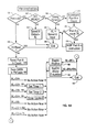
- Fig. 4A depicts typical I/O requests which are made by the audio application.
- An I/O request is sent along input line 99 and intercepted by a code module 100 which determines to which port the application was writing.
- the ports in the diagram are listed as xx1 through xxF which represent a sequence of 16 adjacent ports which the personal computer recognizes as ports allocated to the audio card. For example, the ports may be 220 through 22F or 380 through 38F.
- the audio application will attempt to send the I/O request to a specific I/O port.
- I/O ports xx1, xx2 and xx3 are used for C/MS 404 quality synthesizer (another type other then FM synth) NOT widely popular music processing.
- I/O port xx6 is used for DSP reset processing.
- I/O port xx8 and xx9 are used for FM music control processing.
- I/O port xxA is used for DSP voice I/O and MIDI read data.
- I/O port xxC is used for DSP/command processing.
- I/O port xxE is used for the DSP data available status.
- the I/O handling routine 100 traps the instructions which are intended for a specific hardware port and sends them to the appropriate procedure.
- I/O commands or data to the xxO through xx3 ports are sent to the C/MS music voice routine 102.
- the C/MS music voice routine is a specialized synthesis routine which very few applications use. Thus, the VDD need not support this routine, although it could be performed similarly to the FM synthesis routine in figs. 6A-61.
- I/O commands to the xx6 port are sent to the DSP reset procedure 104 which is depicted in greater detail in fig. 5.
- I/O commands for FM synthesis are normally sent to ports xx8 and xx9. After interception, they are sent to the FM synthesis procedure 106 shown in greater detail in figs.
- I/O to the xxA port is sent to the Read Data Procedure 108 depicted in fig. 7.
- I/O to the xxC port is sent to the write Data/CMD procedure 110 depicted in figs. 8A-81.
- the DSP Data Available/Status procedure described in conjunction with fig. 9 receives the I/O data intended for the xxE port.
- I/O instructions to the other ports in the figure are treated as NOPs.
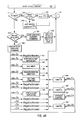
- the I/O handling routine can be much simpler depending on the audio card to which the application is intended to write. For example, in fig. 4B, the I/O handling routine for an MPU TM card manufactured by the Roland Corporation is illustrated.
- the I/O instructions from the application are intercepted by the MPU I/O handling routine block 120 which determines whether the I/O instruction is data or command/status information bound for port xx0 or xx1. If it is data information, normally received at the first port, it is sent to the data block 122. If it is command or status information, normally sent to the xx1 port, the I/O instruction is handled by the command / status block 124.
- a plurality of I/O handlers are provided to handle audio input/output data written for a plurality of different hardware platforms.
- a first application written for the SoundBlasterTM card could operate concurrently with a second application written for an MPU card, where the actual audio I/O operations are performed by a third audio card for which neither the first and second application were written.
- Figs. 5-9 accompany a more detailed description of the processes in the modules in fig. 4A.
- specific values for various parameters are given which are based on the expectations of an audio appreciation written to directly read or write to the SoundBlasterTM card.
- One skilled in the art would recognize that similar procedures could be written for the I/O handler depicted in fig. 4B, and other I/O handlers for other hardware, but that the specific parameters may differ from those below.
- the processes are not depicted as traditional state machines, they respond with a particular function to the I/O instruction and state of the audio applications.
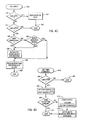
- Fig. 5 depicts the process to reset a digital signal processor.
- a DSP reset command is being performed on the card.
- the process begins in step 130 with a DSP reset command.
- a test is performed, step 132, to determine whether the input is an I/O read. If it is an I/O read, the output variable is set to FFh in step 134 and returned to the audio application.
- xx6 port is a write only port. If a write only port is read the hardware which is emulated by the embodiment of the invention returns FFh.
- steps 136, 140 and 142 tests are performed to determine whether the I/O input from the application equals certain values. If so, the I/O value is saved in step 138 for future use by the VDD.
- step 146 the savedE variable is set to FFh indicate that data is available from the DSP and the savedA variable is set to AAh to indicate that the xxA part should be setup with the data from the DSP.
- the VDD contains a table which stores the last input to and last output from a particular "port". For example, a savedA input value is the value to be sent back to application on next read access of xxA port. A savedA output value is the last value written to xxA port by application.
- step 148 all processing on the audio card is stopped as the application has asked that the DSP be reset and the buffers are returned to the operating system.
- port xxE and port xxA are read the next time, the correct values will be waiting to be sent to the application. The process ends in step 150.
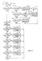
- Figs. 6A through 61 depict the process for emulating FM synthesis with the general MIDI instrument interface.
- the process begins in step 160 when port xx8 or xx9 are written to by the audio application.
- Step 160 determines whether a command was written to port xx8 or not. If it was written to port xx8, a test is performed to determine whether the instruction calls for an I/O read operation, step 162. If not, step 164 causes saved8 output to be equal to AL, output data and the process ends, step 165. If the I/O instruction does call for an I/O read, a test is performed to determine whether timers are used by the audio application in step 166.
- step 168 AL is set to saved8 input and the process exits in step 165. If the application does not use any timers, in step 170, a counter for the consecutive times port xx8 is accessed is incremented in count. Next, in step 172, the counter is tested to determine whether to see if five or more reads to the xx8 port have been done in a row. If so, the VDD interface will evaluate the code that the application is processing and if it determines that the application is wasting time, then it will NOP out the instructions in the application code which is performing excessive reads to the port. This speeds up processing considerably and improves performance, step 174. The process continues through steps 168, 165.
- step 176 a test is performed in step 176 to determine whether the application has made an I/O read request. If so, the process exits, step 165. If the application has made an I/O write request, the counter for port xx8 accesses is reset in step 178. Next, the I/O instruction is saved in the FM table, step 180. For same value of the I/O instruction value no action is taken. If the I/O instruction is 02h, an 80 msec timer is set in step 182. If the I/O instruction is 08h, a 320 msec timer is set in step 183. If the I/O instruction is 04h, the timer control procedure is called in step 184. If the I/O instruction equals BDh, the depth/rhythm routine is called in step 188. If the I/O instruction is BOh to B8h the keyon/block routine is called in step 189. The process ends in step 190.
- Fig. 6B describes the set timer 1 routine in greater detail.
- Process begins in step 182 where an I/O instruction of 02h, is detected.
- step 192 the new value of a 80 msec timer is determined before either expires.
- step 192 the least common denominator of Timer 1 and Timer 2 is determined. The least common denominator determines the rate at which VDD timer counters are set up for both Timer 1 and Timer 2, for the number of times the VDD timer needs to go off before Timerl/Timer2 has really expired.
- the tempo is updated on the audio card. The process ends in step 190.
- Fig. C describes the set timer 2 procedure which is basically similar to set timer 1 procedure except that the timer in this case is a 320 msec timer rather than a 80 msec timer in the set timer 1 procedure.
- the process begins in step 183 when the I/O value of 08h is received.
- the new value of the timer is determined before either expires in step 194 as described above in reference to step 192.
- step 195 the tempo on the audio device is updated.
- the process ends in step 190.
- step 184 The timer control procedure is described in greater detail in fig. 6D.
- the process begins in step 184 when an I/O value of 04h is received.
- step 200 a test is performed to determine whether the timers should be reset. If so, in step 202, the saved8 input variable is set to 0.
- step 204 the timer is restarted and the process ends in step 206.
- step 208 a test is performed to determine whether timer 1 should be started. If so, a flag is set in step 210 which indicates that the application is waiting for timer 1 to expire. If not, in step 212, the flag is cleared which indicates that the application is not waiting for timer 1 to expire.
- step 214 a test is performed to determine whether timer 2 should be started. If so, a flag is set in step 216 which indicates that the application is waiting for timer 2 to expire. If not, the flag is cleared which indicates that the application is waiting for timer 2 to expire.
- step 220 a search is performed for the flags indicating that the application is not waiting for timer 1 or timer 2. If the application is waiting for either or both of the timers, the timers are started in step 222 and the process exits, step 206. Restarting the timers basically assures that the timer has expired already and the VDD wants to know when the next timer expires. Starting the timer basically means to start reporting expiration of that timer.
- step 188 the "Drum" procedure is retrieved in response to an I/O instruction equal to BDh.
- step 226 the type of rhythm is determined.
- step 228, the parameters for the rhythm are retrieved by using the bits store in the xx9 port output.
- step 230 a test is performed to determine whether it is a standard rhythm. If it is not a standard rhythm, step 232, finds the closest rhythm using all the parameters. If it is a standard rhythm, step 232 is skipped.
- step 234 the channel 10 note for this rhythm is retrieved, the MIDI channel for rhythm effects.
- the Keyon/block/Fnumber procedure is described in Figs. 6F through 61.
- the process begins in step 189 when an I/O instruction in the range of BOh through B8h is received.
- a test is performed in step 240 to determine whether the audio card is initialized for MIDI yet. If not, the device is initialized to play MIDI, step 242.
- step 244 a test is performed to determine whether a key is turned on. If so, another test is performed in step 246 to determine whether any of the values for this channel have changed since the last time. If they have changed, in step 248, the set voice procedure is called.
- step 250 a test is performed to determine whether a new voice is returned.
- step 252 If so, the new programmed parameters for the new voice are output to the audio card in step 252. If it is not a new voice, step 252 is skipped. In step 254, a test is performed to determine whether the velocity of the voice has changed. If so, the said velocity procedure is called, step 256. Next, the get key procedure is called in step 258. The MIDI message is sent to the audio device in step 260 and the process ends in step 262. If in step 244, the key was not turned on, a test is performed in step 264 to determine whether the note is on at a second time. If so, the velocity is set to 0 in step 266 and the MIDI voice is sent to the audio device. If the note is not on at the second test, the process exits at step 262.
- Fig. 6G describes the set voice procedure in step 248 in greater detail.
- the voice parameters for this channel are received in step 268.
- a test is performed to determine whether the voice has changed, step 270. If not, the same voice is used and the program exits. If the voice has changed, a step is performed in step 272 to determine whether the voice is in the table. If the voice is in the table, the table voice is used. If not, in the step 274, a comparison between the unknown voice and each voice in the table is started.
- step 276 a test is performed to determine whether the connect factors match. If they do, a test is performed to determine whether the wave select carrier matches. If either of these steps fail, in step 280, Vx is set to the maximum.
- step 282 the differences between various parameters for the carrier and modulator are for various MIDI voices are determined.
- a test is performed in step 284 to determine whether there are any more standard voices to test. If not, in step 286, the voice with the least difference from the voice parameters is chosen. The process ends in step 288.
- the actual equation to determine the variance between the unknown voice and each of the standard voices in the table is as follows:
- the equation would translate to half the absolute difference of the Attack(Carrier) of the unknown voice and the Attack(Carrier) of the standard voice PLUS half the absolute difference of the Attack-(Modulator) of the unknown voice and the Attack(Modulator) of the standard voice PLUS half the absolute difference of the Decay(Carrier) of the unknown voice and the Decay(Carrier) of the standard voice PLUS half the absolute difference of the Decay(Modulator) of the unknown voice and the Decay(Modulator) of the standard voice PLUS the absolute difference of the Sustain(Modulator) of the unknown voice and the Sustain(Modulator) of the standard voice multiplied by the absolute difference of the EGtype(modulator) of the unknown voice and the EGtype(modulator) of the standard voice PLUS the half of the absolute difference of the Multiple(modulator) of the unknown voice and the Multiple(modulator) of the standard voice PLUS half of the absolute difference of the TotaILevel(Modulator) of the unknown voice and the TotalLevel-(Modulator) of
- Fig. 6H illustrates the set velocity procedure which begins in step 256 if the velocity has changed.
- step 290 the total level of carrier parameter is retrieved from FM table which was written previously.
- the carrier value is inverted in step 291 and then doubled in step 292.
- the resulting value is returned in step 293.
- Fig. 61 depicts the get key procedure which begins in fig. 6F in step 258.
- the key is the note or frequency that will be played by the hardware.
- step 294 the Fnumber and blockN values for this channel are retrieved. The Fnumber determines the frequency of the output signal and the blockN value determines the octave in the Sound Blaster TM hardware.
- a test is performed in step 295 whether the key is in the table. If so, the key is returned in step 298. If not, the frequency is computed in step 296 using the equation
- step 297 the key which is closest to the computed frequency is found in step 297 and that key returned in step 298.
- Fig. 7 Is a flow diagram for the read data process.
- step 300 the initial I/O input from the application is read.
- step 302 a test is performed to determine whether the I/O data indicates a read access. If not, the program exits, step 303. If it is an I/O read, a test is performed in step 304 to determine whether the last command written to the DSP was E1 h. If not, the I/O data value AL step to the savedA in step 305. The savedE variable is set to FFh in step 306. If the last command to the DSP was E1 h, the audio application expects two more bytes of information to follow. In step 308, a test is performed to determine whether savedA equals 0. If so, steps 305, 306 are performed. If not, the savedA is set to 0 and the procedure returns with a previously saved value for the next read of the xxA port. In step 310, the process ends in step 312.
- Fig. 8A depicts a flow diagram for the write data/command procedure for the present invention.
- step 320 an I/O command from the application is intercepted which indicates that a write data or write command operation to the card is sought by the audio application.
- step 322 a test is performed to determined whether it is an I/O read command. If so, a second test is performed whether the interface or audio controller card need to wait in step 324. If not, the AL value is set to FFh, step 326, which indicates that the DSP is ready to receive the next command and the program exits 328. If the program interface needs to stall, AL is set to the latest value in savedC and the new value in savedC is set to 7Fh. This indicates that the DSP is not ready to receive any more commands at the present time. The process proceeds to exit, step 328.
- step 332 If the I/O instruction is not an I/O read operation, a test is performed whether the interface is waiting for more than 1 byte of data for this command. step 332. If so, in step 334, the I/O data is saved for the current command. In step 336, the number of bytes the state machine is waiting for is determined. The process proceeds to the exit, step 328.
- step 340 If the interface is waiting for more than 1 byte, the byte of I/O data is saved for the command in step 340. Once all the DATA bytes for the command have been received, the VDD continues down past step 340 to process the command which may be for either MIDI, PCM or ADPCM. For example, if the command is Ox, 5x, 6x, 9x, Ax, Bx, Cx, the process will proceed to exit, step 328. If the command is equal to 1x, an 8 bits digital to analog converter (DAC) and a two-bit analog digital PMC DAC procedure, step 341, is performed. If the command equals 2x, an analog to digital converter input procedure step 342, is performed.
- DAC digital to analog converter
- step 344 the set time constant procedure is performed if the command is equal to 4x.
- a 4 bit and 2.6 bit AD PMC DAC is set in step 345 if the command is equal to 7x.
- step 346 the command 8x procedure in step 346 is performed.
- the speaker control procedure in step 347 is performed if the command is equal to Dx.
- the command Ex or the command Fx procedures are performed if the command equals Ex or Fx in steps 348 and 349 respectively.
- Fig. 8B depicts a flow diagram for the DMA write mode to a 8-bit DAC, one of the several DSP write commands supported by the Sound Blaster TM protocol.
- the other write commands are a direct write to an 8- bit DAC, a DMA write mode to a 2-bit Adaptive Delta Pulse Code Modulation (ADPCM) DAC, a second DMA write mode to a 2-bit ADPCM DAC with a reference byte and a direct write mode DAC.
- ADPCM is a compression algorithm used by the DSP on the SoundBlaster. For sake of simplicity, only the first write mode associated with this command is depicted. Also, depending on the audio hardware, not all of these write modes can be supported unless they are provided by the VDD.
- step 341 a test is performed for the h I/O instruction which indicates that the DMA write mode for the 8-bit DAC is called by the application.
- step 352 the DSP is set to busy and savedC is set to FFh.
- step 354 determines whether the DMA write has halted. If so, in step 356, data processing is halted and in step 358 the DMA halted flag is cleared. If the DMA write is proceeding, step 360 tests for a new sample rate. If the sample rate stays stable, in step 362, a test is performed whether the audio card is initialized for PCM. If not, the process continues with step 364 which is a test for changes which need to be executed.
- step 366 If there are outstanding changes, a test for tempo changes is performed in step 366. If there are tempo changes, the flag for changing tempos is cleared in step 368. The process proceeds to step 370 where the audio hardware is initialized for the PCM operation. In step 372, the DMA data to be written to the device is sent. The process ends, step 374.
- Fig. 8C depicts the process for analog to digital converter input to the audio card which might come from a microphone or other audio source. If 20h is the I/O instruction, the information is written directly to the audio card, step 380. If 24h is the I/O instruction, the information is written via a DMA mode, step 383. After the ADC input command, 2x, is received from the application, step 342, two tests are performed in steps 380 and 383 whether the expected types of ADC input modes have been specified. If the direct mode is specified, a command for the data to be read by the card in step 381 is sent. If neither command is detected, the procedure ends, step 382.
- step 384 a test for whether a new sample rate is requested is performed. If the same sample rate is requested, a test whether the audio card is properly initialized for recording is done in step 386. The process continues to step 388 if a new sample rate or proper initialization of the audio device is required.
- step 390 a buffer is read for the specified number of bytes in the DMA read operation. The process ends, step 392.
- Fig. 8D depicts the set time constant procedure which is used to set the sampling rate for the DAC and ADC in DMA modes.
- the only I/O instruction recognized is 40h. If the test in step 400, is negative, the process ends, step 402. If the application desires to change the sampling rate, in step 404, the DSP is set to busy and the savedC variable is set to FFh. Next, a test is performed in step 406 to determine whether the time constant is the same as last time, e.g., the sampling rate is constant. If not, the new sample rate is calculated using the formula: in step 408. The flag is set to indicate that a new sample rate is available in step 410. The process ends in step 412.
- Fig. 8E is the flow diagram for the 4-bit ADPCM and 2.6 bit ADPCM DAC modes which are similar to those discussed in conjunction with FIG. 8B. If the I/O instruction does not fall between 74h and 77h, after the tests in step 420 or 421, the process will end. If the I/O instruction does fall within this range, the audio application intended to use one of several write modes supported by the SoundBlaster" card. However, in this embodiment, none of the modes are supported by the audio hardware for which the VDD is built and the designer of the VDD did not choose to emulate support with the VDD. Therefore, the data which sent by the application is simply thrown away.
- step 422 a test is performed to determine whether the DMA data has been entered into the buffer. If not, a flag is set so the buffer is ignored when it is received. If so, a interrupt on the IRQ level that the application thinks it's audio devices is running on is sent to the application. The process ends in step 426.
- the "CMD 8x" write mode is depicted in fig. 8F. It was found that emulating general undocumented operations was necessary to "fool" certain audio applications that they were interacting with the SoundBlaster TI Several of these nodes appear to be testing modes, but it was also found that acceptable performance was possible by simply emulating the expected response, even if there was no actual knowledge of what the hardware was actually doing. Thus, reverse assembly or access to source code is not necessary. Although the CMD 8x mode is not documented, several audio applications use this mode to test the SoundBlasterTM card to determine which interrupts the card is using and whether these interrupts are working. If data is being played on the audio hardware associated with the VDD, this routine waits for the play to finish.
- step 346 the VDD returns an interrupt at the level which the application would expect to receive one.
- step 346 a test is performed to determine whether the I/O instruction is 80h in step 430. If not, the process ends. If so, the process continues to step 431 where the VDD waits until all the audio data has been processed by the card.
- step 432 a "virtual" DMA interrupt is sent to the application. The process ends, step 433.
- Fig. 8G shows the speaker control process.
- a test is performed for the DOh I/O instruction which indicates that the DMA operation between the computer and the DSP on the audio card should be halted. If the DOh instruction is sent, step 436 sets the flag to halt the DMA operation and step 438 stops the data currently processing. If the D1 h I/O instruction is detected in step 440, it means that the speaker should be turned on. In step 442, the command to turn the speaker on is sent to the audio card. If the D3h command is detected in step 444, it means that the speaker should be turned off. Consequently, in step 446, the command to turn the speaker off is sent to the audio card. The presence of the D4h command is tested in step 448. If found, the halted DMA operation is resumed in step 450. The process ends in step 452.
- the CMD Ex operation is depicted in fig. 8H. These are all commands done by the application to test to see if the audio card is functioning correctly or not.
- a test for a E2h command from the audio application is conducted. If the command is not detected, a test in step 461 for EOh is conducted. If successful, the savedE variable is set to FFh and the savedA variable is set to the inverse of data bytes. The process exits in step 463. If the test in step 461 fails, a test for an I/O instruction of E4h is performed in step 464. If this test is successful, in step 465, a test for the being set to E8h is conducted.
- step 465 test If the step 465 test is successful, the savedE variable is set to FFh and the savedA variable is set to the least significant in step 466. If either of the tests in steps 464 and 465 are unsuccessful, a test for an E1 h I/O instruction is performed in step 467. If E1 h is found, the savedE variable is set to FFh and the savedA variable is set to 02h. The process ends in step 463.
- step 469 If the I/O instruction was E2h, a flag is set in step 469 to stall the application.E2 command is followed by another byte of info for the command.
- This command checks the DMA operation.
- step 470 if the data byte is 94h, 07h is written to the address specified for the DMA operation in step 471.
- step 472 if the data byte is equal to BAh, D6h is written to the address specified by the DMA operation in step 473.
- steps 474, 476 or 478 successfully detect an I/O instruction of A5h, 06h or 6Bh respectively, DDh, 3Ah or 08h is written to the address specified by the DMA operation in steps 475, 477 or 479 respectively.
- step 480 ends, step 480.
- step 484 a test in step 484 is performed to determine whether the I/O instruction intercepted from the application is F8h. If so, the savedE variable is set to FFh and the savedA variable is set to 00h meaning data is available to be read from DSP in the xxA port.
- a second test is performed in step 487 to determine whether the I/O instruction from the audio application is F2h. If so, step 488 sends an interrupt to the application on the IRQ level that the emulated device would have been using. This is done by applications at initialization to determine what IRQ the hardware is setup to use. The process ends in step 486.
- Fig. 9 illustrates the DSP Data Available Status process which is used to tell the audio application that there is data available in the DSP for it to read.
- the process begins in step 490.
- a test is performed in step 491 whether the application has requested an I/O read process. If not, the process ends, step 492. If so, the output AL is set to the value stored in the savedE variable.
- the following tables list the audio parameters used with the SoundBlasterTM set to the interface module and the MIDI voices which the interface module sends to the audio device driver or the audio hardware.
- Table 2 presents General MIDI voices are selected using MIDI program change messages.
- Table 3 lists 128 general MIDI instrument sounds.
- Fig. 10 depicts the audio controller card which includes a DSP 33 for the correction of the speaker response.
- One possible audio controller is the M-Audio Capture and Playback Adapter announced and shipped on September 18, 1990 by the IBM Corporation.
- the I/O bus is a microchannel or PC I/O bus 500 which allows the personal computer to pass information via the I/O bus 500 to the audio controller.
- a command register 502, a status register 504 and address high byte counter 506 and address low byte counter 507, a high data high byte bidirectional latch 508, and a data low bidirectional latch 510 are also included on the audio controller card.
- the registers are used by the personal computer to issue commands and monitor the status of the audio controller card.
- the address and data latches are used by the personal computer to access the shared memory 512, which is an 8K by 16 bit static RAM on the audio controller card.
- the shared memory 512 also provides a means of communication between the personal computer and the digital signal processor 33.
- a memory arbiter part of the control logic 514, prevents the personal computer and the DSP 33 from accessing the shared memory 512 at the same time.
- the shared memory 512 can be divided so that part of the stored information is logic used to control the digital signal processor 33.
- the digital signal processor has its own control registers 516 and status registers 518 for issuing commands and monitoring the status of other parts of the audio controller card.
- the audio controller card contains another block of RAM called the sample memory 520.
- the sample memory 520 is a 2K by 16 bit static RAM which the DSP 33 uses to store outgoing audio signals to be played on the speaker systems or store incoming signals of digitized audio.
- the digital analog converter (DAC) 522 and the analog digital converter (ADC) 524 convert the audio signal between the digital environment of the computer and the analog sound produced or received by the speakers.
- the DAC 522 receives digital samples from the sample memory 520, converts the samples to analog signals and sends these signals to the analog output section 526.
- the analog output section 526 conditions and sends the digital signals provided by the personal computer to the output connectors for transmission via the speaker system. As the DAC 522 is multiplexed, continuous stereo operation can be given to both right and left speaker components.
- the ADC 524 is the counterpart of the DAC 522.
- the ADC 524 receives analog signals from the analog input section 528 which receives the signals from a microphone or another audio input device such as a tape player.
- the ADC 524 converts the analog signals to digital, samples and stores them in the sample memory 520.
- the control logic 514 issues interrupts to the personal computer after the DSP 33 has issued an interrupt request.
- the personal computer informs the DSP 33 that the audio card should play a particular sample of digitized sound data.
- the personal computer gets the digital audio samples from its memory or disk storage and transfers them to the shared memory 512 through the I/O bus 500.
- the DSP 33 takes the samples and converts them to scaled values and places them in the sample memory 520.
- the DSP 33 then activates the DAC 522 which converts the digitized samples into audio signals, the audio output section 526 conditions the audio signals and places them on the output connectors.
- the DSP code implements an 8 channel sound generator. A data area associated with each sound generator is written to by the Audio Device Driver just prior to sounding a note. The Audio Device Driver maintains a table of 175 sets of these data, one per sound or program change.
- the Audio Device Driver Upon receipt of a MIDI program change, the Audio Device Driver simply saves away the new program change number for use when subsequent Note-Ons occur on that MIDI channel. Upon receipt of a Note-On event, the Audio Device Driver recalls the program change number for the Note-On's MIDI channel number. It then selects either an unused DSP sound generator. If none are available it forces the oldest sounding note to the off state. It then copies the voicing information for the program number into the selected sound generator, and sets a bit telling the sound generator to begin making sound.
- Any MIDI Control Changes received result in the associated data, for example, pitch for pitch bend, volume for volume change, etc., being updated or modified for each currently sounding note assigned to the MIDI channel specified in the Control Change.
- Control Changes can occur prior to a Note-On event and will still be reflected in the Note-On's received after the Control Change. This is done by saving info about the current state of all control changes and using this data at Note-On time.
Abstract
A system and method for handling audio input/output data translates audio message in a first format from an audio application resident in a virtual machine to an audio voice in a second format which may have no exact match for the original audio message. The audio applications directly write to a particular hardware register of a particular audio card to communicate with an audio card which operates according to completely different principles. The translating program intercepts the audio message written in the first format including a first plurality of audio parameters, compares the audio parameters to those corresponding to a table of audio voices and selects the audio voice which corresponds to a match of the audio parameters in the audio message. If there is no exact match in the table, a variety of means are provided to calculate the closest audio voice for the original audio message.
Description
- This invention relates generally to sound reproduction on a personal computer. More particularly, it relates to a method and system for decoding binary data written to specific hardware registers to a generalized interface protocol such as the Musical Instrument Digital Interface (MIDI).
- In the personal computer industry, there exists a plurality of special purpose adapter cards to perform various functions. For example, a variety of game cards, device adapter cards to add computer peripherals, video cards and communication cards exist. Generally, the personal computer has a certain number of slots available to integrate these adapter cards in the computer. Approximately three years ago, Creative Labs Inc. introduced a new audio adapter card called the SoundBlaster TI which has become the industry standard for computer games. Today, virtually every software product which uses audio provides support for the SoundBlaster™.
- Other audio cards must support the vast number of existing audio applications to be commercially viable. Unfortunately, most of these applications perform direct read/write operations to the SoundBlaster TI hardware registers. One solution for compatibility in the prior art is to have a similar chip set with similar registers.
- However, developing a clone card is very limiting and does little to advance the audio technology. It would be preferable to enable the great number of existing audio applications to operate on any hardware platform. FM synthesis on the SoundBlaster TM does not operate according to the Musical Instrument Digital Interface (MIDI), an important industry standard for musical application, but instead on its own esoteric protocol. Further, as the technology of audio cards advances, the existing application must be supported or the lack of consumer acceptance will greatly hinder progress.
- It is therefore an object of the invention to create a hardware independent platform for audio applications.
- It is another an object of the invention to interpret an arbitrary set of data to the midi interface.
- It is another object of the invention to improve music synthesis.
- It is another object of the invention to allow any audio hardware to interface with audio applications which perform direct read operations to registers.
- The invention as claimed accomplishes these objects and others by intercepting and analyzing output from an audio application to attempt to categorize it as to type of data and for command. After the analysis, a table lookup is performed which matches audio data values to each of the 175 general MIDI instrument sounds. If there is no exact match, an attempt is made to determine which of the 175 general MIDI sounds is closest. Further, the data can be used to alter one or more of the MIDI control variables to vary the audio output from the general MIDI instrument.
- Preferably, the invention is carried out by the use of an interface Virtual Device Driver (VDD) or a Terminate Stay Residence (TSR) module depending on the operating system. The interface module can intercept instructions while saving status information on the audio application. This allows the virtual device driver to interrogate and restore the intercepted instruction to a form compatible with an audio device driver or directly with an audio card. As generalized specifications exist for the audio device driver, it can be written for any particular audio card making the interface module completely hardware independent. The operating system creates a virtual machine in which the audio application will run. After the trapped I/O instructions are analyzed, they are onto the other modules of the interface module for transformation. These transformation modules can take the form of state machine. For example, a Pulse Code Modulation (PCM) state machine performs PCM record and playback emulation. A frequency modulation (FM) synthesizer state machine performs the MIDI and FM synthesis emulation.
- These and other objects and features will become more easily understood by reference with the attached drawings and following description.
- Figure 1 is a representation of a multimedia personal computer system including the system unit, keyboard, mouse and multimedia display equipped with a speaker system.
- Figure 2 is a block diagram of the multimedia computer system components of a preferred embodiment of the invention.
- Figure 3 is an architectural diagram of the code modules in RAM coupled to the audio device and audio device driver according to the present invention.
- Figures 4A and 4B are diagrams of the generalized flows for I/O request handlers which intercept I/O from audio applications to the various ports of two different audio cards.
- Figure 5 is a flow diagram of the digital signal processor (DSP) reset function.
- Figures 6A - 61 are flow diagrams of the FM synthesis procedure.
- Figure 7 is a flow diagram of a data read procedure.
- Figures 8A - 81 are flow diagrams of the data or command write procedure.
- Figure 9 is a flow diagram of a DSP data available status procedure.
- Fig. 10 depicts an audio controller card which can be used with the present invention.
- The invention can be incorporated in the display of a variety of computers. The processor unit could be for example, a personal computer, a mini computer or a mainframe computer, running the plurality of computer displays. The computer may be a standalone system, part of a network, such as a local area network or wide area network or a larger teleprocessing system. Most preferably, however, the invention as described below is implemented on a standalone multimedia personal computer, such as IBM's PS/2 multimedia series, although the specific choice of a computer is limited only by the resource requirements, e.g., memory and disk storage of multimedia programming. For additional information on IBM's PS/2 series of computers, readers referred to Technical Reference Manual Personal System/2
Model personal computer 10, comprising asystem unit 11, akeyboard 12, amouse 13 and adisplay 14 are depicted. Also depicted are thespeaker systems monitor 14. Thescreen 16 ofdisplay device 14 is used to present the visual components multimedia presentation. Thespeaker system display 14 itself. Thespeaker systems - Fig. 2 shows a block diagram of the components of the multimedia personal computer shown in fig. 1. The
system unit 11 includes a system bus orbusses 21 to which various components are coupled and by which communication between the various components is accomplished. Amicroprocessor 22 is connected to thesystem bus 21 and is supported by read only memory (ROM) 23 and random access memory (RAM) 24 also connected tosystem bus 21. A microprocessor in the IBM multimedia PS/2 series of computers is one of the Intel family of microprocessors including the 8088, 80286, 80386 or 80486 microprocessors, however, other microprocessors included, but not limited to Motorola's family of microprocessors such as the 68000, 68020 or the 68030 microprocessors and various Reduced Instruction Set Computer (RISC) microprocessors manufactured by IBM, Hewett Packard, Sun, Intel, Motorola and others may be used in the specific computer. TheROM 23 contains among other code the Basic Input/Output System (BIOS) which controls basic hardware operations such as the interaction and the disk drives and the keyboard. TheRAM 24 is the main memory into which the operating system and multimedia application programs are loaded. Thememory management chip 25 is connected to thesystem bus 21 and controls Direct Memory Access (DMA) operations including passing data between theRAM 24 andhard disk drive 26 andfloppy disk drive 27. A CD ROM also coupled to thesystem bus 21 may be used to store the large amount of data present in a multimedia program or presentation. - Also connected to this
system bus 21 are various I/O controllers. thekeyboard controller 28, the mouse controller 29, thevideo controller 30, and theaudio controller 31. As might be expected, thekeyboard controller 28 provides the hardware interface for thekeyboard 12, the mouse controller 29 provides the hardware interface for themouse 13, thevideo controller 30 is the hardware interface for thedisplay 14, and theaudio controller 31 is the hardware interface for thespeakers audio controller 31. - Fig. 3 depicts an architectural block diagram of the code modules in memory coupled to an audio device according to one preferred embodiment of the present invention. The
application 50 is maintained in a virtual machine by the operating system. The I/O instructions from anaudio application 50 or itsaudio device drivers 52 are trapped by the virtual device driver (VDD) 54. In practice, almost all existing audio applications communicate without the use of the device drivers, intending to write directly to the hardware registers. TheVDD 54 communicates with the audio device driver (ADD) 56. Similarly, it translates messages from theADD 56 into a form usable to theapplication 50. TheADD 56 is coupled directly to theaudio device 58 and shields the other code modules from needing any knowledge of the hardware in the audio device. In an alternative embodiment, theVDD 54 reads and writes directly to the audio card. However, in this embodiment the VDD is not hardware independent. The audio card is described in detail in connection with FIG. 10. Within theVDD 54, there are code modules for the I/O interruptroutines 60, astate machine 62, audio API calls 64 and acallback routine 66. - When the
VDD 54 is installed or a virtual machine session is created, the VDD tells the operating system that it is interested in knowing when accesses to a list of I/O addresses occur. After this, every time one of the I/O ports is accessed, control is transferred to the VDD I/O intercept routine 60. These routines set up calls to the device specific portion of the device driver, i.e. adevice state machine 62. This routine 60 will look at the port that was accessed, whether the I/O instruction was a request for a read or write access, and what the data was that was being written (if a write access) to the port. Theintercept routine 60 takes all this information and does any of the necessary processing to translate this information into the audio API calls/information 64. The audio API calls 64 are a set of routines that make calls the physicalaudio device driver 56 that controls the audio device to which the translated audio information is sent. One preferred API is covered in the Audio Device Drivers for IBM Personal Computers specification which is available from the IBM Corporation and hereby incorporated by reference. The audio device may send interrupts when certain events have occurred, such as the completion of processing the data. TheADD 56 will then inform theVDD 54 of the event by calling thecallback routine 66. Thecallback routine 66 is used mainly mostly for identifying when a buffer of PCM data which the application requested to be DMAed to the audio device has completed playing. When theVDD 54 receives the callback, it will then send a "virtual" IRQ to the application to let theapplication 50 know that the "DMA" has completed processing. - When the VDD is installed, it tells the operating system what DMA channels it is interested in, similar to hooking the I/O ports. For SoundBlaster,
DMA channel 1 is used. From now on, the VDD will get control whenever MASK or MASK_OFF event on the DMA is done. If it is our VDD doing the MASKing, then we want to find out the data buffer being DMAed so it can be sent to the audio device driver. We determine if it is our VDD by checking the id of the process that is doing the access to the DMA (which is supplied by the operating system) with the id of the process that has been doing accesses to the audio I/O ports. - The physical address of the data buffer to be DMAed and the size of the buffer can be read from the DMA registers. However, in OS/2 this presents a problem. OS/2 has a virtual device driver for the DMA. Because of this, every time the DMA is programmed by a process, the DMA virtual device driver intercepts the information. The actual programming of the DMA is done only after control has been passed to our virtual device driver. So at the time that the DMA Handler gets control, the data address and size is not available in the DMA registers. To get around this, a timer is set in the DMA Handler to go off as soon as possible (1 msec) at which time a DMA Timer routine is given control. By the time the timer expires, the DMA Handler has returned to the OS/2 virtual DMA device driver and it has programmed the DMA with the data address and size. The DMA Timer routine can then go and read the information it needs from the DMA registers.
- The data buffer is then sent to the audio device driver (56). When the audio device driver is finished processing the data, it will give a callback (66) to the virtual device driver. At this time, the virtual device driver will generate an interrupt on the same interrupt level that the DMA would have. The application sees this interrupt and continues with the next buffer of data to be processed.
- For DOS and Windows, the size and address of the data is available at the time the DMA Handler is given control. Therefore, none of the extra processing is required.
- An interesting feature of the intel 80386 and above microprocessors is its virtual 8086 or V86 mode of operation. In this mode, a virtual 8086 machine is created. Audio applications may be run on this V86 virtual machine under the control of operating system code. Privileged instructions intended for a hardware register can be trapped by the operating system which also stores status information on the application to allow the operating system to interrogate and restore the instruction. A virtual device driver may be used to intercept codes from the audio application in the virtual 86 machine. Whenever the audio application attempts a read or write to one of the known audio register I/O locations, the virtual device driver intercepts the instruction and emulates it using the functions available with the substituted audio hardware.
- The 80386 processor can run in real (normal under DOS), protected, or virtual-8086 (or V86) modes. The V86 mode is designed to run real-mode programs in a protect- mode environment. For example, as in running DOS programs in the OS/2 "DOS-box". When in V86 mode, the processor compares the port address of each IN/OUT instruction against a bitmap which defines which ports the current program is privileged to access. If the corresponding bitmap bit is a "I", the access is not allowed and a protect fault will occur.
- The interface module may also be implemented as a Terminate Stay Residence (TSR) module that enters protect mode and then exits back to V86 mode with the bitmap set for the desired I/O ports. As part of entering protect mode, a Global Descriptor Table (GDT), a Local Descriptor Table(LDT), an Interrupt Descriptor Table(IDT), and a TASK State Segment (TSS) must all be initialized. After the TSR returns to DOS, all subsequent programs will run in V86 mode. Protect faults due to accesses of selected I/O ports will be handled by the TSR. The I/O instructions can then be conveniently mapped to other I/O ports and/or program functions as required. All software interrupts will also cause a protect fault. The TSR must recognize the software interrupts and pass them on to the correct software interrupt handler via the interrupt vector table.
- In OS/2 2.0 and Windows 3.1, a virtual device driver can be used to trap I/O interrupts to a physical device driver, e.g., an audio device driver, or directly to a hardware registers. Many existing applications were written to use the entire resources of the computer system and thus can not operate in a multiapplication environment without assistance from the operating system. The virtual device driver allows applications to share a hardware resource such as an audio card. Typically, the VDD is used simply to trap the I/O data and send it to the appropriate port with little transformation of the data into another form. This is true as the application is writing to the same hardware or device driver as it was in the single application environment. In the present invention, the VDD is different as it causes the application to interact with completely different hardware than that for which it was originally written.
- The virtual device driver is comprised of a basic hyperviser, and state machines that provide FM synthesizer and other audio functions. The basic hyperviser performs the trapping of I/O instructions and passes the trapped instructions to the state machines. In addition, the VDD emulates the operation of the Direct Memory Access DMA controller. Variable sample rates between 4 thousand and twenty-three thousand samples per second are supported by Sound Blaster TM audio hardware. As the substitute audio hardware may not be able to support the arbitrary sample rate selected by the application, the physical device driver will map the requested sample rate to the nearest available rate.
- When the VDD is installed, it tells the operating system what DMA channels it is interested in, similar to hooking the I/O ports. For SoundBlaster,
DMA channel 1 is used. The VDD will get control whenever MASK or MASK_OFF event on the DMA is performed. If it is the V86 machine which the audio application is resident doing the MASKing, then the VDD finds out which data buffer is being DMAed so. The DMA data can be sent to the audio device driver. The VDD determines if it is the audio applications virtual machine by checking the id of the process that is doing the access to the DMA (which is supplied by the operating system) with the id of the process that has been doing accesses to the audio I/O ports. - The physical address of the data buffer to be DMAed and the size of the buffer can be read from the DMA registers. However, in OS/2 this presents the same problem already described.
- For DOS and Windows, the size and address of the data is available at the time the DMA Handler is given control. Therefore, none of the extra processing is required.
- The FM synthesizer state machine performs a MIDI and FM synthesizes emulation. The FM synthesizer register data written to the FM registers is analyzed and converted to MIDI data conforming to the general MIDI recommended practice. General MIDI is NOT a standard - just a recommended practice. The frequency data in Table 1 is used to determine the MIDI note to use. The data in Table 1 is used to determine which general MIDI instrument sound is to be generated. This may result in the generation of a MIDI program change if there is a change in any parameter in Table 1. Also, a slight difference in the total level of the carrier is used to determine the MIDI Note-on value.
- The following parameters are used with the SoundBlaster™ to determine the note to be played:

- Fig. 4A depicts typical I/O requests which are made by the audio application. An I/O request is sent along
input line 99 and intercepted by acode module 100 which determines to which port the application was writing. The ports in the diagram are listed as xx1 through xxF which represent a sequence of 16 adjacent ports which the personal computer recognizes as ports allocated to the audio card. For example, the ports may be 220 through 22F or 380 through 38F. Depending on the nature of the I/O request, the audio application will attempt to send the I/O request to a specific I/O port. In the SoundBlaster™ audio card, I/O ports xx1, xx2 and xx3 are used for C/MS 404 quality synthesizer (another type other then FM synth) NOT widely popular music processing. I/O port xx6 is used for DSP reset processing. I/O port xx8 and xx9 are used for FM music control processing. I/O port xxA is used for DSP voice I/O and MIDI read data. I/O port xxC is used for DSP/command processing. I/O port xxE is used for the DSP data available status. - The I/O handling routine 100 traps the instructions which are intended for a specific hardware port and sends them to the appropriate procedure. I/O commands or data to the xxO through xx3 ports are sent to the C/MS
music voice routine 102. The C/MS music voice routine is a specialized synthesis routine which very few applications use. Thus, the VDD need not support this routine, although it could be performed similarly to the FM synthesis routine in figs. 6A-61. I/O commands to the xx6 port are sent to theDSP reset procedure 104 which is depicted in greater detail in fig. 5. I/O commands for FM synthesis are normally sent to ports xx8 and xx9. After interception, they are sent to the FM synthesis procedure 106 shown in greater detail in figs. 6A-61. I/O to the xxA port is sent to theRead Data Procedure 108 depicted in fig. 7. I/O to the xxC port is sent to the write Data/CMD procedure 110 depicted in figs. 8A-81. The DSP Data Available/Status procedure described in conjunction with fig. 9 receives the I/O data intended for the xxE port. I/O instructions to the other ports in the figure are treated as NOPs. The I/O handling routine can be much simpler depending on the audio card to which the application is intended to write. For example, in fig. 4B, the I/O handling routine for an MPU TM card manufactured by the Roland Corporation is illustrated. The I/O instructions from the application are intercepted by the MPU I/O handlingroutine block 120 which determines whether the I/O instruction is data or command/status information bound for port xx0 or xx1. If it is data information, normally received at the first port, it is sent to the data block 122. If it is command or status information, normally sent to the xx1 port, the I/O instruction is handled by the command / status block 124. In one preferred embodiment of the invention, a plurality of I/O handlers are provided to handle audio input/output data written for a plurality of different hardware platforms. Thus, a first application written for the SoundBlaster™ card could operate concurrently with a second application written for an MPU card, where the actual audio I/O operations are performed by a third audio card for which neither the first and second application were written. - Figs. 5-9 accompany a more detailed description of the processes in the modules in fig. 4A. In these flow diagrams, specific values for various parameters are given which are based on the expectations of an audio appreciation written to directly read or write to the SoundBlaster™ card. One skilled in the art would recognize that similar procedures could be written for the I/O handler depicted in fig. 4B, and other I/O handlers for other hardware, but that the specific parameters may differ from those below. Although the processes are not depicted as traditional state machines, they respond with a particular function to the I/O instruction and state of the audio applications.
- Fig. 5 depicts the process to reset a digital signal processor. When the xx6 port is written, a DSP reset command is being performed on the card. The process begins in
step 130 with a DSP reset command. Next, a test is performed,step 132, to determine whether the input is an I/O read. If it is an I/O read, the output variable is set to FFh instep 134 and returned to the audio application. xx6 port is a write only port. If a write only port is read the hardware which is emulated by the embodiment of the invention returns FFh. Insteps step 138 for future use by the VDD. If not, a test is performed to determine whether an input value of 01 h had previously been saved,step 144. If so, instep 146, the savedE variable is set to FFh indicate that data is available from the DSP and the savedA variable is set to AAh to indicate that the xxA part should be setup with the data from the DSP. Throughout the diagrams whenever savedE is set to FFh, it means that there is data available in the xxA port to read. The VDD contains a table which stores the last input to and last output from a particular "port". For example, a savedA input value is the value to be sent back to application on next read access of xxA port. A savedA output value is the last value written to xxA port by application. Instep 148, all processing on the audio card is stopped as the application has asked that the DSP be reset and the buffers are returned to the operating system. When port xxE and port xxA are read the next time, the correct values will be waiting to be sent to the application. The process ends instep 150. - Figs. 6A through 61 depict the process for emulating FM synthesis with the general MIDI instrument interface. The process begins in
step 160 when port xx8 or xx9 are written to by the audio application. Step 160 determines whether a command was written to port xx8 or not. If it was written to port xx8, a test is performed to determine whether the instruction calls for an I/O read operation,step 162. If not, step 164 causes saved8 output to be equal to AL, output data and the process ends,step 165. If the I/O instruction does call for an I/O read, a test is performed to determine whether timers are used by the audio application instep 166. If the application does use timers, instep 168, AL is set to saved8 input and the process exits instep 165. If the application does not use any timers, instep 170, a counter for the consecutive times port xx8 is accessed is incremented in count. Next, instep 172, the counter is tested to determine whether to see if five or more reads to the xx8 port have been done in a row. If so, the VDD interface will evaluate the code that the application is processing and if it determines that the application is wasting time, then it will NOP out the instructions in the application code which is performing excessive reads to the port. This speeds up processing considerably and improves performance,step 174. The process continues throughsteps step 176 to determine whether the application has made an I/O read request. If so, the process exits,step 165. If the application has made an I/O write request, the counter for port xx8 accesses is reset instep 178. Next, the I/O instruction is saved in the FM table, step 180. For same value of the I/O instruction value no action is taken. If the I/O instruction is 02h, an 80 msec timer is set instep 182. If the I/O instruction is 08h, a 320 msec timer is set instep 183. If the I/O instruction is 04h, the timer control procedure is called instep 184. If the I/O instruction equals BDh, the depth/rhythm routine is called instep 188. If the I/O instruction is BOh to B8h the keyon/block routine is called instep 189. The process ends instep 190. - Fig. 6B describes the
set timer 1 routine in greater detail. Process begins instep 182 where an I/O instruction of 02h, is detected. Next, instep 192, the new value of a 80 msec timer is determined before either expires. Instep 192, the least common denominator ofTimer 1 andTimer 2 is determined. The least common denominator determines the rate at which VDD timer counters are set up for bothTimer 1 andTimer 2, for the number of times the VDD timer needs to go off before Timerl/Timer2 has really expired. Instep 193, the tempo is updated on the audio card. The process ends instep 190. - Fig. C describes the
set timer 2 procedure which is basically similar to settimer 1 procedure except that the timer in this case is a 320 msec timer rather than a 80 msec timer in theset timer 1 procedure. The process begins instep 183 when the I/O value of 08h is received. Next, the new value of the timer is determined before either expires instep 194 as described above in reference to step 192. Next, instep 195, the tempo on the audio device is updated. The process ends instep 190. - The timer control procedure is described in greater detail in fig. 6D. The process begins in
step 184 when an I/O value of 04h is received. Instep 200, a test is performed to determine whether the timers should be reset. If so, instep 202, the saved8 input variable is set to 0. Next, instep 204, the timer is restarted and the process ends instep 206. If timers are not to be reset, instep 208, a test is performed to determine whethertimer 1 should be started. If so, a flag is set instep 210 which indicates that the application is waiting fortimer 1 to expire. If not, instep 212, the flag is cleared which indicates that the application is not waiting fortimer 1 to expire. Next, instep 214, a test is performed to determine whethertimer 2 should be started. If so, a flag is set instep 216 which indicates that the application is waiting fortimer 2 to expire. If not, the flag is cleared which indicates that the application is waiting fortimer 2 to expire. Next instep 220, a search is performed for the flags indicating that the application is not waiting fortimer 1 ortimer 2. If the application is waiting for either or both of the timers, the timers are started instep 222 and the process exits,step 206. Restarting the timers basically assures that the timer has expired already and the VDD wants to know when the next timer expires. Starting the timer basically means to start reporting expiration of that timer. - The depth and rhythm procedure is described in greater detail in FIG. 6E. First, in
step 188, the "Drum" procedure is retrieved in response to an I/O instruction equal to BDh. Instep 226, the type of rhythm is determined. Instep 228, the parameters for the rhythm are retrieved by using the bits store in the xx9 port output. Next, instep 230, a test is performed to determine whether it is a standard rhythm. If it is not a standard rhythm,step 232, finds the closest rhythm using all the parameters. If it is a standard rhythm,step 232 is skipped. Next, instep 234, thechannel 10 note for this rhythm is retrieved, the MIDI channel for rhythm effects. Finally, instep 236, the voice onchannel 10 is returned to the application. - The Keyon/block/Fnumber procedure is described in Figs. 6F through 61. The process begins in
step 189 when an I/O instruction in the range of BOh through B8h is received. A test is performed instep 240 to determine whether the audio card is initialized for MIDI yet. If not, the device is initialized to play MIDI,step 242. Instep 244, a test is performed to determine whether a key is turned on. If so, another test is performed instep 246 to determine whether any of the values for this channel have changed since the last time. If they have changed, instep 248, the set voice procedure is called. Next, instep 250, a test is performed to determine whether a new voice is returned. If so, the new programmed parameters for the new voice are output to the audio card instep 252. If it is not a new voice,step 252 is skipped. Instep 254, a test is performed to determine whether the velocity of the voice has changed. If so, the said velocity procedure is called,step 256. Next, the get key procedure is called instep 258. The MIDI message is sent to the audio device instep 260 and the process ends instep 262. If instep 244, the key was not turned on, a test is performed instep 264 to determine whether the note is on at a second time. If so, the velocity is set to 0 instep 266 and the MIDI voice is sent to the audio device. If the note is not on at the second test, the process exits atstep 262. - Fig. 6G describes the set voice procedure in
step 248 in greater detail. First, the voice parameters for this channel are received instep 268. A test is performed to determine whether the voice has changed,step 270. If not, the same voice is used and the program exits. If the voice has changed, a step is performed instep 272 to determine whether the voice is in the table. If the voice is in the table, the table voice is used. If not, in thestep 274, a comparison between the unknown voice and each voice in the table is started. Instep 276, a test is performed to determine whether the connect factors match. If they do, a test is performed to determine whether the wave select carrier matches. If either of these steps fail, instep 280, Vx is set to the maximum. Thus, this voice will be too different to be deemed the closest voice in thestep 286 below. Instep 282, the differences between various parameters for the carrier and modulator are for various MIDI voices are determined. A test is performed instep 284 to determine whether there are any more standard voices to test. If not, instep 286, the voice with the least difference from the voice parameters is chosen. The process ends instep 288. The actual equation to determine the variance between the unknown voice and each of the standard voices in the table is as follows: -

- In standard English, the equation would translate to half the absolute difference of the Attack(Carrier) of the unknown voice and the Attack(Carrier) of the standard voice PLUS half the absolute difference of the Attack-(Modulator) of the unknown voice and the Attack(Modulator) of the standard voice PLUS half the absolute difference of the Decay(Carrier) of the unknown voice and the Decay(Carrier) of the standard voice PLUS half the absolute difference of the Decay(Modulator) of the unknown voice and the Decay(Modulator) of the standard voice PLUS the absolute difference of the Sustain(Modulator) of the unknown voice and the Sustain(Modulator) of the standard voice multiplied by the absolute difference of the EGtype(modulator) of the unknown voice and the EGtype(modulator) of the standard voice PLUS the half of the absolute difference of the Multiple(modulator) of the unknown voice and the Multiple(modulator) of the standard voice PLUS half of the absolute difference of the TotaILevel(Modulator) of the unknown voice and the TotalLevel-(Modulator) of the standard voice PLUS half of the absolute difference of the Feedback(Modulator) of the unknown voice and the Feedback(modulator) of the standard voice.
- Fig. 6H illustrates the set velocity procedure which begins in
step 256 if the velocity has changed. Instep 290, the total level of carrier parameter is retrieved from FM table which was written previously. The carrier value is inverted instep 291 and then doubled instep 292. The resulting value is returned instep 293. - Fig. 61 depicts the get key procedure which begins in fig. 6F in
step 258. The key is the note or frequency that will be played by the hardware. Next, instep 294, the Fnumber and blockN values for this channel are retrieved. The Fnumber determines the frequency of the output signal and the blockN value determines the octave in the Sound Blaster TM hardware. Next, a test is performed instep 295 whether the key is in the table. If so, the key is returned instep 298. If not, the frequency is computed instep 296 using the equation
- Next, the key which is closest to the computed frequency is found in
step 297 and that key returned instep 298. - Fig. 7 Is a flow diagram for the read data process. First, in
step 300 the initial I/O input from the application is read. Instep 302, a test is performed to determine whether the I/O data indicates a read access. If not, the program exits,step 303. If it is an I/O read, a test is performed instep 304 to determine whether the last command written to the DSP was E1 h. If not, the I/O data value AL step to the savedA instep 305. The savedE variable is set to FFh instep 306. If the last command to the DSP was E1 h, the audio application expects two more bytes of information to follow. Instep 308, a test is performed to determine whether savedA equals 0. If so, steps 305, 306 are performed. If not, the savedA is set to 0 and the procedure returns with a previously saved value for the next read of the xxA port. Instep 310, the process ends instep 312. - Fig. 8A depicts a flow diagram for the write data/command procedure for the present invention. In
step 320, an I/O command from the application is intercepted which indicates that a write data or write command operation to the card is sought by the audio application. Instep 322, a test is performed to determined whether it is an I/O read command. If so, a second test is performed whether the interface or audio controller card need to wait instep 324. If not, the AL value is set to FFh,step 326, which indicates that the DSP is ready to receive the next command and the program exits 328. If the program interface needs to stall, AL is set to the latest value in savedC and the new value in savedC is set to 7Fh. This indicates that the DSP is not ready to receive any more commands at the present time. The process proceeds to exit,step 328. - If the I/O instruction is not an I/O read operation, a test is performed whether the interface is waiting for more than 1 byte of data for this command.
step 332. If so, instep 334, the I/O data is saved for the current command. Instep 336, the number of bytes the state machine is waiting for is determined. The process proceeds to the exit,step 328. - If the interface is waiting for more than 1 byte, the byte of I/O data is saved for the command in
step 340. Once all the DATA bytes for the command have been received, the VDD continues downpast step 340 to process the command which may be for either MIDI, PCM or ADPCM. For example, if the command is Ox, 5x, 6x, 9x, Ax, Bx, Cx, the process will proceed to exit,step 328. If the command is equal to 1x, an 8 bits digital to analog converter (DAC) and a two-bit analog digital PMC DAC procedure,step 341, is performed. If the command equals 2x, an analog to digital converterinput procedure step 342, is performed. If the command equals 3x, a read or write to a MIDI port instep 343 is performed. Instep 344, the set time constant procedure is performed if the command is equal to 4x. A 4 bit and 2.6 bit AD PMC DAC is set instep 345 if the command is equal to 7x. If the command is equal to 8x, the command 8x procedure instep 346 is performed. The speaker control procedure instep 347 is performed if the command is equal to Dx. The command Ex or the command Fx procedures are performed if the command equals Ex or Fx insteps - Fig. 8B depicts a flow diagram for the DMA write mode to a 8-bit DAC, one of the several DSP write commands supported by the Sound Blaster TM protocol. The other write commands are a direct write to an 8- bit DAC, a DMA write mode to a 2-bit Adaptive Delta Pulse Code Modulation (ADPCM) DAC, a second DMA write mode to a 2-bit ADPCM DAC with a reference byte and a direct write mode DAC. The ADPCM is a compression algorithm used by the DSP on the SoundBlaster. For sake of simplicity, only the first write mode associated with this command is depicted. Also, depending on the audio hardware, not all of these write modes can be supported unless they are provided by the VDD.
- after the 1x command in
step 341, a test is performed for the h I/O instruction which indicates that the DMA write mode for the 8-bit DAC is called by the application. Next, instep 352, the DSP is set to busy and savedC is set to FFh. A test instep 354 determines whether the DMA write has halted. If so, instep 356, data processing is halted and instep 358 the DMA halted flag is cleared. If the DMA write is proceeding, step 360 tests for a new sample rate. If the sample rate stays stable, instep 362, a test is performed whether the audio card is initialized for PCM. If not, the process continues withstep 364 which is a test for changes which need to be executed. If there are outstanding changes, a test for tempo changes is performed instep 366. If there are tempo changes, the flag for changing tempos is cleared instep 368. The process proceeds to step 370 where the audio hardware is initialized for the PCM operation. Instep 372, the DMA data to be written to the device is sent. The process ends,step 374. - Fig. 8C depicts the process for analog to digital converter input to the audio card which might come from a microphone or other audio source. If 20h is the I/O instruction, the information is written directly to the audio card,
step 380. If 24h is the I/O instruction, the information is written via a DMA mode,step 383. After the ADC input command, 2x, is received from the application,step 342, two tests are performed insteps step 381 is sent. If neither command is detected, the procedure ends,step 382. - If the DMA mode is called, in
step 384, a test for whether a new sample rate is requested is performed. If the same sample rate is requested, a test whether the audio card is properly initialized for recording is done instep 386. The process continues to step 388 if a new sample rate or proper initialization of the audio device is required. Next, instep 390, a buffer is read for the specified number of bytes in the DMA read operation. The process ends,step 392. - Fig. 8D depicts the set time constant procedure which is used to set the sampling rate for the DAC and ADC in DMA modes. The only I/O instruction recognized is 40h. If the test in
step 400, is negative, the process ends,step 402. If the application desires to change the sampling rate, instep 404, the DSP is set to busy and the savedC variable is set to FFh. Next, a test is performed instep 406 to determine whether the time constant is the same as last time, e.g., the sampling rate is constant. If not, the new sample rate is calculated using the formula:
instep 408. The flag is set to indicate that a new sample rate is available instep 410. The process ends instep 412. - Fig. 8E is the flow diagram for the 4-bit ADPCM and 2.6 bit ADPCM DAC modes which are similar to those discussed in conjunction with FIG. 8B. If the I/O instruction does not fall between 74h and 77h, after the tests in
step step 426. - The "CMD 8x" write mode is depicted in fig. 8F. It was found that emulating general undocumented operations was necessary to "fool" certain audio applications that they were interacting with the SoundBlaster TI Several of these nodes appear to be testing modes, but it was also found that acceptable performance was possible by simply emulating the expected response, even if there was no actual knowledge of what the hardware was actually doing. Thus, reverse assembly or access to source code is not necessary. Although the CMD 8x mode is not documented, several audio applications use this mode to test the SoundBlaster™ card to determine which interrupts the card is using and whether these interrupts are working. If data is being played on the audio hardware associated with the VDD, this routine waits for the play to finish. At this point the VDD returns an interrupt at the level which the application would expect to receive one. After the command 8x is received by the application in
step 346, a test is performed to determine whether the I/O instruction is 80h instep 430. If not, the process ends. If so, the process continues to step 431 where the VDD waits until all the audio data has been processed by the card. Next instep 432, a "virtual" DMA interrupt is sent to the application. The process ends,step 433. - Fig. 8G shows the speaker control process. After the process is started in
step 347, a test is performed for the DOh I/O instruction which indicates that the DMA operation between the computer and the DSP on the audio card should be halted. If the DOh instruction is sent,step 436 sets the flag to halt the DMA operation and step 438 stops the data currently processing. If the D1 h I/O instruction is detected instep 440, it means that the speaker should be turned on. Instep 442, the command to turn the speaker on is sent to the audio card. If the D3h command is detected instep 444, it means that the speaker should be turned off. Consequently, instep 446, the command to turn the speaker off is sent to the audio card. The presence of the D4h command is tested instep 448. If found, the halted DMA operation is resumed instep 450. The process ends instep 452. - The CMD Ex operation is depicted in fig. 8H. These are all commands done by the application to test to see if the audio card is functioning correctly or not. After initializing in
step 348, a test for a E2h command from the audio application is conducted. If the command is not detected, a test instep 461 for EOh is conducted. If successful, the savedE variable is set to FFh and the savedA variable is set to the inverse of data bytes. The process exits instep 463. If the test instep 461 fails, a test for an I/O instruction of E4h is performed instep 464. If this test is successful, instep 465, a test for the being set to E8h is conducted. If thestep 465 test is successful, the savedE variable is set to FFh and the savedA variable is set to the least significant instep 466. If either of the tests insteps step 467. If E1 h is found, the savedE variable is set to FFh and the savedA variable is set to 02h. The process ends instep 463. - If the I/O instruction was E2h, a flag is set in
step 469 to stall the application.E2 command is followed by another byte of info for the command. This command checks the DMA operation. Instep 470, if the data byte is 94h, 07h is written to the address specified for the DMA operation instep 471. Instep 472, if the data byte is equal to BAh, D6h is written to the address specified by the DMA operation instep 473. Similarly, if the tests insteps steps step 480. - In fig. 81, the CMD Fx operation is depicted. This is another undocumented operation with which some applications interact with the SoundBlaster™. After starting in
step 349, a test instep 484 is performed to determine whether the I/O instruction intercepted from the application is F8h. If so, the savedE variable is set to FFh and the savedA variable is set to 00h meaning data is available to be read from DSP in the xxA port. A second test is performed instep 487 to determine whether the I/O instruction from the audio application is F2h. If so,step 488 sends an interrupt to the application on the IRQ level that the emulated device would have been using. This is done by applications at initialization to determine what IRQ the hardware is setup to use. The process ends instep 486. - Fig. 9 illustrates the DSP Data Available Status process which is used to tell the audio application that there is data available in the DSP for it to read. The process begins in
step 490. A test is performed instep 491 whether the application has requested an I/O read process. If not, the process ends,step 492. If so, the output AL is set to the value stored in the savedE variable. - The following tables list the audio parameters used with the SoundBlaster™ set to the interface module and the MIDI voices which the interface module sends to the audio device driver or the audio hardware.
- The parameters in TABLE 1 are used with the SoundBlaster™ Card to produce a sound:

- Table 2 presents General MIDI voices are selected using MIDI program change messages.

- Table 3 lists 128 general MIDI instrument sounds.

- Fig. 10 depicts the audio controller card which includes a
DSP 33 for the correction of the speaker response. One possible audio controller is the M-Audio Capture and Playback Adapter announced and shipped on September 18, 1990 by the IBM Corporation. Referring to FIG. 10, the I/O bus is a microchannel or PC I/O bus 500 which allows the personal computer to pass information via the I/O bus 500 to the audio controller. Acommand register 502, astatus register 504 and addresshigh byte counter 506 and addresslow byte counter 507, a high data high bytebidirectional latch 508, and a data lowbidirectional latch 510 are also included on the audio controller card. The registers are used by the personal computer to issue commands and monitor the status of the audio controller card. The address and data latches are used by the personal computer to access the sharedmemory 512, which is an 8K by 16 bit static RAM on the audio controller card. The sharedmemory 512 also provides a means of communication between the personal computer and thedigital signal processor 33. - A memory arbiter, part of the
control logic 514, prevents the personal computer and theDSP 33 from accessing the sharedmemory 512 at the same time. The sharedmemory 512 can be divided so that part of the stored information is logic used to control thedigital signal processor 33. The digital signal processor has its own control registers 516 and status registers 518 for issuing commands and monitoring the status of other parts of the audio controller card. The audio controller card contains another block of RAM called thesample memory 520. Thesample memory 520 is a 2K by 16 bit static RAM which theDSP 33 uses to store outgoing audio signals to be played on the speaker systems or store incoming signals of digitized audio. The digital analog converter (DAC) 522 and the analog digital converter (ADC) 524, convert the audio signal between the digital environment of the computer and the analog sound produced or received by the speakers. TheDAC 522 receives digital samples from thesample memory 520, converts the samples to analog signals and sends these signals to theanalog output section 526. Theanalog output section 526 conditions and sends the digital signals provided by the personal computer to the output connectors for transmission via the speaker system. As theDAC 522 is multiplexed, continuous stereo operation can be given to both right and left speaker components. - The
ADC 524 is the counterpart of theDAC 522. TheADC 524 receives analog signals from theanalog input section 528 which receives the signals from a microphone or another audio input device such as a tape player. TheADC 524 converts the analog signals to digital, samples and stores them in thesample memory 520. Thecontrol logic 514 issues interrupts to the personal computer after theDSP 33 has issued an interrupt request. - Providing a stereo audio signal to the speaker system works in the following way. The personal computer informs the
DSP 33 that the audio card should play a particular sample of digitized sound data. In the subject invention, the personal computer gets the digital audio samples from its memory or disk storage and transfers them to the sharedmemory 512 through the I/O bus 500. TheDSP 33 takes the samples and converts them to scaled values and places them in thesample memory 520. TheDSP 33 then activates theDAC 522 which converts the digitized samples into audio signals, theaudio output section 526 conditions the audio signals and places them on the output connectors. - The DSP code implements an 8 channel sound generator. A data area associated with each sound generator is written to by the Audio Device Driver just prior to sounding a note. The Audio Device Driver maintains a table of 175 sets of these data, one per sound or program change.
- Upon receipt of a MIDI program change, the Audio Device Driver simply saves away the new program change number for use when subsequent Note-Ons occur on that MIDI channel. Upon receipt of a Note-On event, the Audio Device Driver recalls the program change number for the Note-On's MIDI channel number. It then selects either an unused DSP sound generator. If none are available it forces the oldest sounding note to the off state. It then copies the voicing information for the program number into the selected sound generator, and sets a bit telling the sound generator to begin making sound.
- Any MIDI Control Changes received result in the associated data, for example, pitch for pitch bend, volume for volume change, etc., being updated or modified for each currently sounding note assigned to the MIDI channel specified in the Control Change. Control Changes can occur prior to a Note-On event and will still be reflected in the Note-On's received after the Control Change. This is done by saving info about the current state of all control changes and using this data at Note-On time.
Claims (17)
1. A method for translating audio data in a first format from an audio application (50) resident in the memory (24) of a computer system to a second format comprising the steps of:
intercepting an audio message written in the first format including a first plurality of audio parameters;
comparing said audio message to a table of audio voices each of which corresponds to a selected set of audio parameters; and,
selecting the audio voice which corresponds to an exact match of said first plurality of audio parameters.
2. The method as recited in claim 1 which further comprises the steps of:
calculating which of the selected sets of audio parameters is closest to said first plurality of audio parameters, if none of the selected sets is an exact match; and,
selecting the audio voice which corresponds to the closest set of audio parameters.
3. The method as recited in claim 2 which further comprises the steps of:
comparing each of the selected sets of audio parameters to said first plurality of audio parameters determining whether a connect factors audio parameter in each selected set matches a first connect factors audio parameter in said first plurality of audio parameters; and,
discarding any selected set of audio parameters whose connect factors audio parameter does not match the first connect factors audio parameter.
4. The method as recited in claim 2 which further comprises the steps of:
comparing each of the selected sets of audio parameters to said first plurality of audio parameters;
determining whether a wave carrier audio parameter in each selected set matches a first wave carrier audio parameter in said first plurality of audio parameters; and,
discarding any selected set of audio parameters whose wave carrier audio parameter does not match the first wave carrier audio parameter.
5. The method as recited in claim 2 which further comprises the steps of:
comparing each of the selected sets of audio parameters to said first plurality of audio parameters;
determining whether a value of a first audio parameter in each selected set matches a value of the first audio parameter in said first plurality of audio parameters; and,
discarding any selected set of audio parameters whose first audio parameter value does not match the first audio parameter value of said first plurality of audio parameters.
6. The method as recited in any preceding claim which further comprises the steps of:
maintaining the audio application (50) in a virtual machine in an operating system; and,
sending the selected voice to an audio card different from that for which the application was originally written.
7. The method as recited in any preceding claim wherein the audio parameters are a plurality of FM synthesis parameters and the audio voices are a set of generalized MIDI voices.
8. The method as recited in claim 2 which further comprises the steps of:
determining a difference between a first audio parameter in said first plurality and the first audio parameter in the closest set; and,
altering the audio voice according to the difference.
9. The method as recited in claim 2 which further comprises the steps of:
comparing a first audio parameter in said first plurality to the respective first audio parameters corresponding to a selected group of the audio voices in said table, if the closest set of audio parameters exceeds a predetermined difference from said first plurality; and,
selecting the audio voice in the selected group of audio voice whose first audio parameter matches said first audio parameter in the first plurality.
10. A system for translating audio data in a first format from an audio application to a second format comprising:
a memory (24) for storing sets of instructions for performing computer functions, the sets of instructions including the audio application and a translating means;
a processor (22) coupled to the memory for carrying out the sets of instructions;
an audio card coupled to the processor for performing audio functions according to an I/O instruction from the audio application (50);
said translating means comprising;
means for intercepting an audio message written in the first format including a first plurality of audio parameters;
means for comparing the audio message to a table of audio voices each of which corresponds to a selected set of audio parameters;
means for selecting the audio voice which corresponds to an exact match of said first plurality of audio parameters.
11. The system as recited in claim 10 wherein the translating program further comprises:
means for calculating which of the selected sets of audio parameters is closest to said first plurality of audio parameters, if none of the selected sets is an exact match; and,
means for selecting the audio voice which corresponds to the closest set of audio parameters.
12. The system as recited in claim 11 wherein said translating means further comprises:
means for comparing each of the selected sets of audio parameters to said first plurality of audio parameters;
means for determining whether a value of a first audio parameter in each selected set matches a value of the first audio parameter in said first plurality of audio parameters; and,
means for discarding any selected set of audio parameters whose first audio parameter value does not match the first audio parameter value of said first plurality of audio parameters.
13. The system as recited in any claim from 10 to 12 which further comprises:
a virtual machine in an operating system in which to maintain the audio application; and,
means for sending the selected voice to the audio card, the audio card different from that for which the application was originally written.
14. The system as recited in any claim from 10 to 13 wherein the audio parameters are a plurality of FM synthesis parameters and the audio voices are a set of generalized MIDI voices.
15. The system as recited in claim 11 wherein said translating means further comprises:
means for determining a difference between a first audio parameter in said first plurality and the first audio parameter in the closest set; and,
means for altering the audio voice according to the difference.
16. The system as recited in claim 11 wherein said translating means further comprises:
means for comparing a first audio parameter in said first plurality to the respective first audio parameters corresponding to a selected group of the audio voices in said table, if the closest set of audio parameters exceeds a predetermined difference from said first plurality; and,
means for selecting the audio voice in the selected group of audio voice whose first audio parameter matches the first audio parameter in said first plurality.
17. The system as recited in any claim from 10 to 16 which further comprises:
an audio card which understands audio input/output data in the second format for performing audio functions according to an I/O instruction from the audio application.
Applications Claiming Priority (2)
| Application Number | Priority Date | Filing Date | Title |
|---|---|---|---|
| US97575492A | 1992-11-13 | 1992-11-13 | |
| US975754 | 1992-11-13 |
Publications (2)
| Publication Number | Publication Date |
|---|---|
| EP0597381A2 true EP0597381A2 (en) | 1994-05-18 |
| EP0597381A3 EP0597381A3 (en) | 1994-08-10 |
Family
ID=25523353
Family Applications (1)
| Application Number | Title | Priority Date | Filing Date |
|---|---|---|---|
| EP19930117843 Withdrawn EP0597381A3 (en) | 1992-11-13 | 1993-11-04 | Method and system for decoding binary data for audio application. |
Country Status (3)
| Country | Link |
|---|---|
| US (1) | US5515474A (en) |
| EP (1) | EP0597381A3 (en) |
| JP (1) | JPH07146679A (en) |
Cited By (21)
| Publication number | Priority date | Publication date | Assignee | Title |
|---|---|---|---|---|
| EP0694902A1 (en) * | 1994-07-18 | 1996-01-31 | Yamaha Corporation | Electronic musical instrument having an effect data converting function |
| EP0713206A1 (en) * | 1994-11-16 | 1996-05-22 | Yamaha Corporation | Electronic musical instrument changing timbre by external designation of multiple choices |
| EP0715295A1 (en) * | 1994-11-29 | 1996-06-05 | Yamaha Corporation | Automatic playing apparatus substituting available pattern for absent pattern |
| EP0730260A2 (en) * | 1995-03-03 | 1996-09-04 | Yamaha Corporation | Computerized music apparatus composed of compatible software modules |
| EP0747877A2 (en) * | 1995-06-06 | 1996-12-11 | Yamaha Corporation | Computerized music system having software and hardware sound sources |
| EP0715296A3 (en) * | 1994-12-02 | 1997-01-15 | Sony Corp | Sound source controlling device |
| EP0769773A1 (en) * | 1995-10-20 | 1997-04-23 | Yamaha Corporation | Tone generating method and device |
| EP0770983A1 (en) * | 1995-10-23 | 1997-05-02 | Yamaha Corporation | Sound generation method using hardware and software sound sources |
| EP0780827A1 (en) * | 1995-12-21 | 1997-06-25 | Yamaha Corporation | Method and device for generating a tone |
| EP0785539A1 (en) * | 1996-01-17 | 1997-07-23 | Yamaha Corporation | Tone generator system using computer software |
| WO1997036283A1 (en) * | 1996-03-25 | 1997-10-02 | Advanced Micro Devices, Inc. | Computer system and method for performing wavetable music synthesis |
| EP0786758A3 (en) * | 1996-01-26 | 1998-01-07 | Yamaha Corporation | Electronic musical system controlling chain of sound sources |
| EP0827133A1 (en) * | 1996-08-30 | 1998-03-04 | Yamaha Corporation | Method and apparatus for generating musical tones, processing and reproducing music data using storage means |
| EP0845138A2 (en) * | 1995-08-14 | 1998-06-03 | Creative Technology Ltd. | Method and apparatus for formatting digital audio data |
| US5809342A (en) * | 1996-03-25 | 1998-09-15 | Advanced Micro Devices, Inc. | Computer system and method for generating delay-based audio effects in a wavetable music synthesizer which stores wavetable data in system memory |
| US5895877A (en) * | 1995-05-19 | 1999-04-20 | Yamaha Corporation | Tone generating method and device |
| US6034314A (en) * | 1996-08-29 | 2000-03-07 | Yamaha Corporation | Automatic performance data conversion system |
| EP1087370A1 (en) * | 1999-09-27 | 2001-03-28 | Yamaha Corporation | Method and apparatus for producing a waveform based on a style-of-rendition module |
| USRE41297E1 (en) | 1995-07-05 | 2010-05-04 | Yamaha Corporation | Tone waveform generating method and apparatus based on software |
| US8250573B2 (en) * | 2007-12-27 | 2012-08-21 | Intel Corporation | Audio subsystem sharing in a virtualized environment |
| US10140084B2 (en) | 2000-10-12 | 2018-11-27 | Bose Corporation | Interactive sound reproducing |
Families Citing this family (15)
| Publication number | Priority date | Publication date | Assignee | Title |
|---|---|---|---|---|
| US5574934A (en) * | 1993-11-24 | 1996-11-12 | Intel Corporation | Preemptive priority-based transmission of signals using virtual channels |
| US6707484B1 (en) * | 1994-07-28 | 2004-03-16 | Semiconductor Energy Laboratory Co., Ltd. | Information processing system |
| CA2135506C (en) * | 1994-11-09 | 1999-06-08 | Patrick K. Kam | I/o trapping for sound generation in the computer |
| US5732279A (en) * | 1994-11-10 | 1998-03-24 | Brooktree Corporation | System and method for command processing or emulation in a computer system using interrupts, such as emulation of DMA commands using burst mode data transfer for sound or the like |
| DE69721352T2 (en) | 1996-01-31 | 2003-12-24 | Compaq Computer Corp | Computer system with a modem without control |
| US5864710A (en) * | 1996-07-23 | 1999-01-26 | Compaq Computer Corporation | Controllerless modem |
| US5784643A (en) * | 1996-03-28 | 1998-07-21 | International Business Machines Corporation | System incorporating program for intercepting and interpreting or altering commands for generating I/O activity for enabling real-time user feedback by sending substitute characters to modem |
| US5668996A (en) * | 1996-04-29 | 1997-09-16 | Microsoft Corporation | Rendering CD redbook audio using alternative storage locations and formats |
| DE19708755A1 (en) * | 1997-03-04 | 1998-09-17 | Michael Tasler | Flexible interface |
| US6195766B1 (en) * | 1999-05-10 | 2001-02-27 | Conexant Systems, Inc. | System and method for providing soft audio and soft modem copy protection for hardware interfaces and software code |
| US20010044719A1 (en) * | 1999-07-02 | 2001-11-22 | Mitsubishi Electric Research Laboratories, Inc. | Method and system for recognizing, indexing, and searching acoustic signals |
| US20050222844A1 (en) * | 2004-04-01 | 2005-10-06 | Hideya Kawahara | Method and apparatus for generating spatialized audio from non-three-dimensionally aware applications |
| US8001543B2 (en) * | 2005-10-08 | 2011-08-16 | International Business Machines Corporation | Direct-memory access between input/output device and physical memory within virtual machine environment |
| CN104658546B (en) * | 2013-11-19 | 2019-02-01 | 腾讯科技(深圳)有限公司 | Recording treating method and apparatus |
| CN113763970B (en) * | 2021-09-07 | 2023-09-22 | 广州飞傲电子科技有限公司 | Audio transmission method and device and audio transmission equipment |
Citations (2)
| Publication number | Priority date | Publication date | Assignee | Title |
|---|---|---|---|---|
| US4777857A (en) * | 1987-03-10 | 1988-10-18 | Stewart Benjamin U | MIDI address converter and router |
| EP0484043A2 (en) * | 1990-11-01 | 1992-05-06 | International Business Machines Corporation | Translation of midi files |
Family Cites Families (11)
| Publication number | Priority date | Publication date | Assignee | Title |
|---|---|---|---|---|
| FR2476888A1 (en) * | 1980-02-22 | 1981-08-28 | Deforeit Christian | DIGITAL SYNTHESIZER OF SOUND SIGNALS AND APPLICATIONS TO ELECTRONIC MUSICAL INSTRUMENTS |
| JPS5754997A (en) * | 1980-09-19 | 1982-04-01 | Nippon Musical Instruments Mfg | Electronic musical instrument |
| JPS59197090A (en) * | 1983-04-23 | 1984-11-08 | ヤマハ株式会社 | Automatic performer |
| JPS6024591A (en) * | 1983-07-20 | 1985-02-07 | 松下電器産業株式会社 | Music performer |
| US4974151A (en) * | 1985-02-21 | 1990-11-27 | International Business Machines Corporation | Configuration capability for devices in an open system having the capability of adding or changing devices by user commands |
| US4680796A (en) * | 1986-04-11 | 1987-07-14 | Kintek, Inc. | Sound encoding system |
| US4942551A (en) * | 1988-06-24 | 1990-07-17 | Wnm Ventures Inc. | Method and apparatus for storing MIDI information in subcode packs |
| US5208745A (en) * | 1988-07-25 | 1993-05-04 | Electric Power Research Institute | Multimedia interface and method for computer system |
| JP2629891B2 (en) * | 1988-10-01 | 1997-07-16 | ヤマハ株式会社 | Music signal generator |
| US5121667A (en) * | 1989-11-06 | 1992-06-16 | Emery Christopher L | Electronic musical instrument with multiple voices responsive to mutually exclusive ram memory segments |
| US5129036A (en) * | 1990-03-30 | 1992-07-07 | Computer Concepts Corporation | Broadcast digital sound processing system |
-
1993
- 1993-09-27 JP JP5239548A patent/JPH07146679A/en active Pending
- 1993-11-04 EP EP19930117843 patent/EP0597381A3/en not_active Withdrawn
-
1995
- 1995-06-07 US US08/479,246 patent/US5515474A/en not_active Expired - Fee Related
Patent Citations (2)
| Publication number | Priority date | Publication date | Assignee | Title |
|---|---|---|---|---|
| US4777857A (en) * | 1987-03-10 | 1988-10-18 | Stewart Benjamin U | MIDI address converter and router |
| EP0484043A2 (en) * | 1990-11-01 | 1992-05-06 | International Business Machines Corporation | Translation of midi files |
Non-Patent Citations (1)
| Title |
|---|
| IBM TECHNICAL DISCLOSURE BULLETIN, vol.33, no.10B, March 1991, ARMONK, NY, US pages 441 - 443, XP000110272 'PROVISION FOR ALTERNATE MIDI INSTRUMENT-TO-MIDI CHANNEL ASSIGNMENTS' * |
Cited By (50)
| Publication number | Priority date | Publication date | Assignee | Title |
|---|---|---|---|---|
| EP0694902A1 (en) * | 1994-07-18 | 1996-01-31 | Yamaha Corporation | Electronic musical instrument having an effect data converting function |
| US5750914A (en) * | 1994-07-18 | 1998-05-12 | Yamaha Corporation | Electronic musical instrument having an effect data converting function |
| KR100319482B1 (en) * | 1994-07-18 | 2002-04-22 | 우에시마 세이스케 | Electronic musical instrument |
| EP0713206A1 (en) * | 1994-11-16 | 1996-05-22 | Yamaha Corporation | Electronic musical instrument changing timbre by external designation of multiple choices |
| US5998722A (en) * | 1994-11-16 | 1999-12-07 | Yamaha Corporation | Electronic musical instrument changing timbre by external designation of multiple choices |
| EP0715295A1 (en) * | 1994-11-29 | 1996-06-05 | Yamaha Corporation | Automatic playing apparatus substituting available pattern for absent pattern |
| US5696343A (en) * | 1994-11-29 | 1997-12-09 | Yamaha Corporation | Automatic playing apparatus substituting available pattern for absent pattern |
| EP1109149A3 (en) * | 1994-12-02 | 2001-07-18 | Sony Computer Entertainment Inc. | Sound source controlling device |
| US5767430A (en) * | 1994-12-02 | 1998-06-16 | Sony Corporation | Sound source controlling device |
| EP0715296A3 (en) * | 1994-12-02 | 1997-01-15 | Sony Corp | Sound source controlling device |
| EP1109149A2 (en) * | 1994-12-02 | 2001-06-20 | Sony Computer Entertainment Inc. | Sound source controlling device |
| US5898118A (en) * | 1995-03-03 | 1999-04-27 | Yamaha Corporation | Computerized music apparatus composed of compatible software modules |
| EP0730260A3 (en) * | 1995-03-03 | 1997-02-19 | Yamaha Corp | Computerized music apparatus composed of compatible software modules |
| EP0730260A2 (en) * | 1995-03-03 | 1996-09-04 | Yamaha Corporation | Computerized music apparatus composed of compatible software modules |
| US5895877A (en) * | 1995-05-19 | 1999-04-20 | Yamaha Corporation | Tone generating method and device |
| US6184455B1 (en) | 1995-05-19 | 2001-02-06 | Yamaha Corporation | Tone generating method and device |
| EP0747877A3 (en) * | 1995-06-06 | 1997-01-22 | Yamaha Corporation | Computerized music system having software and hardware sound sources |
| EP0747877A2 (en) * | 1995-06-06 | 1996-12-11 | Yamaha Corporation | Computerized music system having software and hardware sound sources |
| USRE37367E1 (en) | 1995-06-06 | 2001-09-18 | Yamaha Corporation | Computerized music system having software and hardware sound sources |
| US5714703A (en) * | 1995-06-06 | 1998-02-03 | Yamaha Corporation | Computerized music system having software and hardware sound sources |
| USRE41297E1 (en) | 1995-07-05 | 2010-05-04 | Yamaha Corporation | Tone waveform generating method and apparatus based on software |
| EP0845138A2 (en) * | 1995-08-14 | 1998-06-03 | Creative Technology Ltd. | Method and apparatus for formatting digital audio data |
| EP0845138A4 (en) * | 1995-08-14 | 1998-10-07 | Creative Tech Ltd | Method and apparatus for formatting digital audio data |
| US5728961A (en) * | 1995-10-20 | 1998-03-17 | Yamaha Corporation | Method and device for executing tone generating processing depending on a computing capability of a processor used |
| EP0769773A1 (en) * | 1995-10-20 | 1997-04-23 | Yamaha Corporation | Tone generating method and device |
| US5750911A (en) * | 1995-10-23 | 1998-05-12 | Yamaha Corporation | Sound generation method using hardware and software sound sources |
| EP0770983A1 (en) * | 1995-10-23 | 1997-05-02 | Yamaha Corporation | Sound generation method using hardware and software sound sources |
| US5973251A (en) * | 1995-12-21 | 1999-10-26 | Yamaha Corporation | Method and apparatus for generating a tone based on tone generating software |
| EP0780827A1 (en) * | 1995-12-21 | 1997-06-25 | Yamaha Corporation | Method and device for generating a tone |
| EP0785539A1 (en) * | 1996-01-17 | 1997-07-23 | Yamaha Corporation | Tone generator system using computer software |
| US6023016A (en) * | 1996-01-17 | 2000-02-08 | Yamaha Corporation | Tone generator system using computer software |
| CN1932969B (en) * | 1996-01-17 | 2011-03-23 | 雅马哈株式会社 | Sound generator system using computer software |
| CN1545084B (en) * | 1996-01-17 | 2010-11-24 | 雅马哈株式会社 | Tone generator system using computer software |
| CN1545084A (en) * | 1996-01-17 | 2004-11-10 | ������������ʽ���� | Tone generator system using computer software |
| EP0786758A3 (en) * | 1996-01-26 | 1998-01-07 | Yamaha Corporation | Electronic musical system controlling chain of sound sources |
| US5831192A (en) * | 1996-01-26 | 1998-11-03 | Yamaha Corporation | Electronic musical system controlling chain of plural sound sources having differing quality |
| US5809342A (en) * | 1996-03-25 | 1998-09-15 | Advanced Micro Devices, Inc. | Computer system and method for generating delay-based audio effects in a wavetable music synthesizer which stores wavetable data in system memory |
| WO1997036283A1 (en) * | 1996-03-25 | 1997-10-02 | Advanced Micro Devices, Inc. | Computer system and method for performing wavetable music synthesis |
| US5763801A (en) * | 1996-03-25 | 1998-06-09 | Advanced Micro Devices, Inc. | Computer system and method for performing wavetable music synthesis which stores wavetable data in system memory |
| US6034314A (en) * | 1996-08-29 | 2000-03-07 | Yamaha Corporation | Automatic performance data conversion system |
| EP0827133A1 (en) * | 1996-08-30 | 1998-03-04 | Yamaha Corporation | Method and apparatus for generating musical tones, processing and reproducing music data using storage means |
| US5850050A (en) * | 1996-08-30 | 1998-12-15 | Yamaha Corporation | Method and apparatus for generating musical tones, method and apparatus for processing music data, method and apparatus reproducing processed music data and storage media for practicing same |
| US6727420B2 (en) | 1999-09-27 | 2004-04-27 | Yamaha Corporation | Method and apparatus for producing a waveform based on a style-of-rendition module |
| EP1688909A1 (en) * | 1999-09-27 | 2006-08-09 | Yamaha Corporation | Method and apparatus for producing a waveform based on a style-of-rendition module |
| EP1087370A1 (en) * | 1999-09-27 | 2001-03-28 | Yamaha Corporation | Method and apparatus for producing a waveform based on a style-of-rendition module |
| US6531652B1 (en) | 1999-09-27 | 2003-03-11 | Yamaha Corporation | Method and apparatus for producing a waveform based on a style-of-rendition module |
| US10140084B2 (en) | 2000-10-12 | 2018-11-27 | Bose Corporation | Interactive sound reproducing |
| US10481855B2 (en) | 2000-10-12 | 2019-11-19 | Bose Corporation | Interactive sound reproducing |
| US8250573B2 (en) * | 2007-12-27 | 2012-08-21 | Intel Corporation | Audio subsystem sharing in a virtualized environment |
| TWI403955B (en) * | 2007-12-27 | 2013-08-01 | Intel Corp | Device,method and system for audio subsystem sharing in a virtualized environment |
Also Published As
| Publication number | Publication date |
|---|---|
| US5515474A (en) | 1996-05-07 |
| EP0597381A3 (en) | 1994-08-10 |
| JPH07146679A (en) | 1995-06-06 |
Similar Documents
| Publication | Publication Date | Title |
|---|---|---|
| EP0597381A2 (en) | Method and system for decoding binary data for audio application | |
| JP2970689B2 (en) | Audio synthesizer | |
| US5703310A (en) | Automatic performance data processing system with judging CPU operation-capacity | |
| US5811706A (en) | Synthesizer system utilizing mass storage devices for real time, low latency access of musical instrument digital samples | |
| US5968148A (en) | High quality audio generation by storing wave tables in system memory and having a DMA controller on the sound board for transferring the wave tables | |
| JPH0683389A (en) | Apparatus and method for speech synthesis | |
| US20020007426A1 (en) | Apparatus and method for playback of waveform sample data | |
| US5444818A (en) | System and method for dynamically configuring synthesizers | |
| JPH09179556A (en) | Method and device for musical tone generation | |
| US20190295517A1 (en) | Electronic musical instrument, method, and storage medium | |
| JPH07181969A (en) | Code segment substitution device, real-time signal processing system using the same, and audio processing system | |
| KR100500077B1 (en) | Tone generating method and device | |
| US5837914A (en) | Electronic carillon system utilizing interpolated fractional address DSP algorithm | |
| JPH09244650A (en) | Musical sound synthesizing device and method | |
| US5956680A (en) | Virtual audio generation and capture in a computer | |
| JP3152198B2 (en) | Music sound generation method and music sound generation device | |
| US20070028751A1 (en) | System for using sound inputs to obtain video display response | |
| JP3572847B2 (en) | Sound source system and method using computer software | |
| US5768631A (en) | Audio adapter card and method for trapping audio command and producing sound corresponding to the trapped command | |
| US6414232B2 (en) | Tone generation method and apparatus based on software | |
| JPH11126069A (en) | Musical sound generating method | |
| JP3339372B2 (en) | Storage medium storing program for realizing musical sound generating apparatus and musical sound generating method | |
| JP4361628B2 (en) | Audio signal generator | |
| JP3127873B2 (en) | Waveform reproducing method, waveform reproducing device, waveform output circuit, and sequence reproducing device | |
| JP3223827B2 (en) | Sound source waveform data generation method and apparatus |
Legal Events
| Date | Code | Title | Description |
|---|---|---|---|
| PUAI | Public reference made under article 153(3) epc to a published international application that has entered the european phase |
Free format text: ORIGINAL CODE: 0009012 |
|
| AK | Designated contracting states |
Kind code of ref document: A2 Designated state(s): DE FR GB |
|
| PUAL | Search report despatched |
Free format text: ORIGINAL CODE: 0009013 |
|
| AK | Designated contracting states |
Kind code of ref document: A3 Designated state(s): DE FR GB |
|
| 17P | Request for examination filed |
Effective date: 19940927 |
|
| STAA | Information on the status of an ep patent application or granted ep patent |
Free format text: STATUS: THE APPLICATION HAS BEEN WITHDRAWN |
|
| 18W | Application withdrawn |
Withdrawal date: 19960927 |