EP0597571B1 - Method and apparatus for processing data for a visual-output device with reduced buffer memory requirements - Google Patents
Method and apparatus for processing data for a visual-output device with reduced buffer memory requirements Download PDFInfo
- Publication number
- EP0597571B1 EP0597571B1 EP93306254A EP93306254A EP0597571B1 EP 0597571 B1 EP0597571 B1 EP 0597571B1 EP 93306254 A EP93306254 A EP 93306254A EP 93306254 A EP93306254 A EP 93306254A EP 0597571 B1 EP0597571 B1 EP 0597571B1
- Authority
- EP
- European Patent Office
- Prior art keywords
- data
- representation
- compression
- region
- compressing
- Prior art date
- Legal status (The legal status is an assumption and is not a legal conclusion. Google has not performed a legal analysis and makes no representation as to the accuracy of the status listed.)
- Expired - Lifetime
Links
- 238000000034 method Methods 0.000 title claims description 113
- 230000015654 memory Effects 0.000 title claims description 62
- 238000012545 processing Methods 0.000 title claims description 17
- 238000007906 compression Methods 0.000 claims description 179
- 230000006835 compression Effects 0.000 claims description 178
- 230000000007 visual effect Effects 0.000 claims description 22
- 230000008569 process Effects 0.000 claims description 18
- 230000006837 decompression Effects 0.000 claims description 11
- 230000007246 mechanism Effects 0.000 claims 16
- 238000004590 computer program Methods 0.000 claims 1
- 238000012544 monitoring process Methods 0.000 claims 1
- 238000010586 diagram Methods 0.000 description 17
- 238000012360 testing method Methods 0.000 description 8
- 239000003086 colorant Substances 0.000 description 5
- 230000008859 change Effects 0.000 description 4
- 238000004891 communication Methods 0.000 description 4
- 230000006870 function Effects 0.000 description 4
- 230000008901 benefit Effects 0.000 description 3
- 238000011161 development Methods 0.000 description 3
- 230000003936 working memory Effects 0.000 description 3
- 238000006243 chemical reaction Methods 0.000 description 2
- 230000000694 effects Effects 0.000 description 2
- 230000009467 reduction Effects 0.000 description 2
- 238000012958 reprocessing Methods 0.000 description 2
- 230000003044 adaptive effect Effects 0.000 description 1
- 238000004458 analytical method Methods 0.000 description 1
- 238000003491 array Methods 0.000 description 1
- 230000015556 catabolic process Effects 0.000 description 1
- 238000007796 conventional method Methods 0.000 description 1
- 238000006731 degradation reaction Methods 0.000 description 1
- 238000007429 general method Methods 0.000 description 1
- 238000012986 modification Methods 0.000 description 1
- 230000004048 modification Effects 0.000 description 1
- 230000000717 retained effect Effects 0.000 description 1
Images


Classifications
-
- H—ELECTRICITY
- H04—ELECTRIC COMMUNICATION TECHNIQUE
- H04N—PICTORIAL COMMUNICATION, e.g. TELEVISION
- H04N1/00—Scanning, transmission or reproduction of documents or the like, e.g. facsimile transmission; Details thereof
- H04N1/41—Bandwidth or redundancy reduction
-
- G—PHYSICS
- G06—COMPUTING; CALCULATING OR COUNTING
- G06K—GRAPHICAL DATA READING; PRESENTATION OF DATA; RECORD CARRIERS; HANDLING RECORD CARRIERS
- G06K15/00—Arrangements for producing a permanent visual presentation of the output data, e.g. computer output printers
-
- G—PHYSICS
- G06—COMPUTING; CALCULATING OR COUNTING
- G06K—GRAPHICAL DATA READING; PRESENTATION OF DATA; RECORD CARRIERS; HANDLING RECORD CARRIERS
- G06K15/00—Arrangements for producing a permanent visual presentation of the output data, e.g. computer output printers
- G06K15/02—Arrangements for producing a permanent visual presentation of the output data, e.g. computer output printers using printers
- G06K15/18—Conditioning data for presenting it to the physical printing elements
- G06K15/1801—Input data handling means
- G06K15/181—Receiving print data characterized by its formatting, e.g. particular page description languages
-
- G—PHYSICS
- G06—COMPUTING; CALCULATING OR COUNTING
- G06K—GRAPHICAL DATA READING; PRESENTATION OF DATA; RECORD CARRIERS; HANDLING RECORD CARRIERS
- G06K15/00—Arrangements for producing a permanent visual presentation of the output data, e.g. computer output printers
- G06K15/02—Arrangements for producing a permanent visual presentation of the output data, e.g. computer output printers using printers
- G06K15/18—Conditioning data for presenting it to the physical printing elements
- G06K15/1848—Generation of the printable image
- G06K15/1849—Generation of the printable image using an intermediate representation, e.g. a list of graphical primitives
- G06K15/1851—Generation of the printable image using an intermediate representation, e.g. a list of graphical primitives parted in a plurality of segments per page
-
- G—PHYSICS
- G06—COMPUTING; CALCULATING OR COUNTING
- G06K—GRAPHICAL DATA READING; PRESENTATION OF DATA; RECORD CARRIERS; HANDLING RECORD CARRIERS
- G06K15/00—Arrangements for producing a permanent visual presentation of the output data, e.g. computer output printers
- G06K15/02—Arrangements for producing a permanent visual presentation of the output data, e.g. computer output printers using printers
- G06K15/18—Conditioning data for presenting it to the physical printing elements
- G06K15/1848—Generation of the printable image
- G06K15/1856—Generation of the printable image characterized by its workflow
- G06K15/1861—Generation of the printable image characterized by its workflow taking account of a limited available memory space or rasterization time
- G06K15/1865—Generation of the printable image characterized by its workflow taking account of a limited available memory space or rasterization time by compressing the rasterized print data
-
- G—PHYSICS
- G06—COMPUTING; CALCULATING OR COUNTING
- G06T—IMAGE DATA PROCESSING OR GENERATION, IN GENERAL
- G06T11/00—2D [Two Dimensional] image generation
- G06T11/60—Editing figures and text; Combining figures or text
-
- G—PHYSICS
- G06—COMPUTING; CALCULATING OR COUNTING
- G06T—IMAGE DATA PROCESSING OR GENERATION, IN GENERAL
- G06T9/00—Image coding
- G06T9/005—Statistical coding, e.g. Huffman, run length coding
-
- G—PHYSICS
- G06—COMPUTING; CALCULATING OR COUNTING
- G06T—IMAGE DATA PROCESSING OR GENERATION, IN GENERAL
- G06T9/00—Image coding
- G06T9/007—Transform coding, e.g. discrete cosine transform
-
- H—ELECTRICITY
- H03—ELECTRONIC CIRCUITRY
- H03M—CODING; DECODING; CODE CONVERSION IN GENERAL
- H03M7/00—Conversion of a code where information is represented by a given sequence or number of digits to a code where the same, similar or subset of information is represented by a different sequence or number of digits
- H03M7/30—Compression; Expansion; Suppression of unnecessary data, e.g. redundancy reduction
-
- G—PHYSICS
- G06—COMPUTING; CALCULATING OR COUNTING
- G06K—GRAPHICAL DATA READING; PRESENTATION OF DATA; RECORD CARRIERS; HANDLING RECORD CARRIERS
- G06K2215/00—Arrangements for producing a permanent visual presentation of the output data
- G06K2215/0002—Handling the output data
- G06K2215/0062—Handling the output data combining generic and host data, e.g. filling a raster
- G06K2215/0065—Page or partial page composition
-
- G—PHYSICS
- G06—COMPUTING; CALCULATING OR COUNTING
- G06K—GRAPHICAL DATA READING; PRESENTATION OF DATA; RECORD CARRIERS; HANDLING RECORD CARRIERS
- G06K2215/00—Arrangements for producing a permanent visual presentation of the output data
- G06K2215/0002—Handling the output data
- G06K2215/0062—Handling the output data combining generic and host data, e.g. filling a raster
- G06K2215/0071—Post-treatment of the composed image, e.g. compression, rotation
Definitions
- This invention relates to a method and apparatus for processing data representative of a visual representation, typically including a combination of text, graphics, and images, that is to be output to a visual-output device, such as a screen display or print device. More particularly it relates to such a method and apparatus in which a data memory, referred to herein functionally as a "buffer memory”, has reduced capacity requirements resulting from the selective compression of data.
- a data memory referred to herein functionally as a "buffer memory”
- the preferred embodiment of, and preferred method of practicing the present invention is directed to printers that form a raster image typically connected indirectly over a network, or directly to a computer for printing documents created on the computer.
- the invention is realizable for other forms of output devices as well, such as a video display generated on a CRT monitor or an LCD.
- the device creating the actual visual representation is referred to as a "visual-output device”.
- the visual area within which the visual representation exists is referred to as a "page”, regardless of its actual form.
- the complete visual representation is referred to as a "page representation”.
- a separately defined part of a page representation is referred to as an "object”.
- a buffer memory also referred to as a frame buffer, for storing raster data defining the page representation.
- Conventional printer configurations employ buffer memories that are capable of storing all of the raster data required to define each pixel on a page. An extensive amount of memory capacity is therefore
- a black-and-white representation for a 8.5 inch x 11 inch sheet of paper at a pixel density of 300 dpi (dots or pixels per inch) requires in excess of 1 MByte (1 million 8-bit bytes) of memory. Higher spatial and tonal resolutions, color printing and larger paper sizes require even more memory.
- a continuous tone, four-color representation at a pixel density of 600 dpi for the same sized page requires about 135 MBytes of memory. Since the printer costs rise with memory size, it is desirable to provide printers with reduced memory requirements.
- Such a conventional technique is known, for instance, from prior art document "Adaptive Coding for Text and Dithered Continuous-Tone Images" by Y. Okada et al., published on FUJITSU SCIENTIFIC AND TECHNICAL JOURNAL, vol. 23, no.2, pages 101-110, 1987, JAPAN.
- This document describes an algorithm wherein it is tested if a currently processed region of an initial image is either a text region or a dithered greyscale image region, two different coding/decoding techniques being applied to each respective region (Modified Huffman or Modified Read for text, P 3 , a template pattern matching technique, for dithered images). Switching between differently encoded regions is controlled by a switching algorithm that counts the number of grey scale codes on the coding line.
- the present invention as set out in the appended claims provides a method for using, and an apparatus permitting a reduced-size memory. Further, it provides a method and apparatus that can accommodate a variety of page representation characteristics and data processing objectives.
- the invention is directed generally to an apparatus and a method for processing data representative of a page representation for output to a visual-output device, such as the electro-mechanical printing apparatus (also referred to as the print device), of a printer.
- the method begins with the step of receiving data that defines a page representation.
- a plurality of regions of the page are selected, which regions contain at least a portion of the page representation.
- separate data for each such region is identified corresponding to the portion of the page representation contained in that region.
- Data identified for at least one of the regions is then compressed, using at least one compression algorithm and stored. For producing the page representation after storing the compressed data, the compressed data is decompressed and transmitted to the visual-output device.
- At least one compression factor and a plurality of compression algorithms are provided.
- the compression factor has a determinable value that is related to a reference value.
- a compression algorithm is then chosen based on the relationship of the determined value of the compression factor to the reference value.
- the preferred embodiment of the invention is an apparatus for printing a two-dimensional page representation composed potentially of text, graphic and image objects (object representations) individually, and in combination.
- a print device is responsive to raster data for printing a page containing the page representation.
- An input device such as a personal computer or workstation, is used for inputting data defining the page representation.
- a program memory stores program instructions including a plurality of different algorithms for compressing the data associated with corresponding different representation types and their combinations. The selection of compression algorithms is based in part on balancing the compression factors of compression ratio, computational complexity, and visual quality.
- a processor is coupled to the input device, print device, program memory and a data memory for executing the stored program instructions.
- the processor is responsive to the data input in the form of descriptive commands for identifying data for each of a plurality of ordered regions or bands containing collectively at least a portion, and preferably, all of the page representation.
- the data for each region corresponds to the portion of the page representation contained in that region. Some regions may not contain data.
- the descriptive commands which are not necessarily band limited, are converted into lists of primitive elements selected from a set of primitive elements. Each primitive element represents at least a portion of an object representation. These lists are referred to as display lists. There is preferably a display list for each region, although the display list could be for the entire page, or for other defined regions.
- the types (and combinations of types) of representations and boundaries (referred to as bounding boxes) of each type contained in each region are determined.
- the display list data associated with the determined types of representations for each region is rasterized into an uncompressed band and then compressed using algorithms corresponding to the analysis of certain compression factors.
- Rasterizing refers generally to the conversion of high-level descriptive commands into rasters. Data associated with primitive elements is often already in raster form. However, for purposes of this discussion, rasterizing refers to the conversion of display list data for a region into raster form without regard for whether or not the data associated with the corresponding primitive elements is already in raster form.
- the compression factors may, and preferably do include compression goals specifying target visual quality, compression ratio, and computational complexity.
- Compression ratio refers generally to the bytes of memory required to hold the compressed data relative to the bytes of memory required to hold the same data uncompressed. Additionally considered are such factors as the type of representation, content of individual bounding boxes, overall content of the page representation, estimated versus actual compression being achieved, and the number of passes or attempts made at compressing the data. Other factors may also be used, and some of these factors may not be used in all situations. For example, the factors could be prioritized so that some are given more weight than others. As an extension of this, in certain situations some factors could be given no weight at all relative to other factors.
- An algorithm generally speaking, refers to a particular algorithm or combination of algorithms with particular parameter values.
- a change in parameter values results in a change in the algorithm.
- the compressed data is stored sequentially by region.
- data for a region is read and decompressed.
- the compressed data may be transmitted to an external printer or stored pending requirement of the data by the print device.
- the data is then transmitted to the print device for printing.
- Producing data (display lists) for each region and defining the regions to conform to the sequential output of raster data to an output device minimizes the number of times the data is decompressed, data added, and then recompressed.
- data defining the page representation takes the form of descriptive commands, display lists and associated information, and raster data.
- Data representative of the page representation is thus compressed and held in memory until such time as it is required by the print device for printing, or until the content of a region is changed.
- the data for the regions are swapped in and out of the compressed-data memory using the selected compression and corresponding decompression algorithms, thereby reducing substantially the buffer memory requirements.
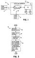
- FIG. 1 is a block diagram of an apparatus made according to and for practicing the method of the invention.
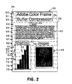
- FIG. 2 is an illustration of a page having different types of two-dimensional representations.
- FIG. 3 is a flow diagram summarizing a method of practicing the invention.
- FIG. 4 is a flow diagram of step 58 of the diagram of FIG. 3.
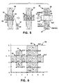
- FIG. 5 illustrates visually the development of non-intersecting bounding boxes from bounding boxes of different representation types that overlap according to the method of the diagram of FIG. 4.
- FIG. 6 is a simplified graphic example of overlapping bounding boxes with identifying coordinates used in the method of the diagram of FIG. 4.
- FIG. 7 is a flow diagram illustrating the development of non-intersecting bounding boxes corresponding to step 122 in FIG. 4.
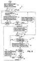
- FIG. 8 is a flow diagram of step 78 of the diagram of FIG. 3.
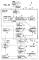
- FIG. 9 is a flow diagram of step 80 of the diagram of FIG. 3.
- FIG. 10 is a functional block diagram corresponding to the apparatus of FIG. 1.
- a generalized visual-representation-generating system made according to the present invention is shown generally at 10. It includes a visual information source 12 connected via a communication link 14 to an output-data generator 16. Generator 16 is connected to a visual-output device 18 via a communication link 20. As will be seen, various embodiments are realizable from this general structure. Output data generator 16 can be resident within a host unit including source 12, can be resident within an output unit including visual-output device 18, or can be functionally split between a host unit and an output unit.
- information source 12 is a conventional work station or other computer-based system, such as an Apple Macintosh or IBM PC.
- print device is also used herein as an example of a visual-output device. In the preferred embodiment, this term applies to the electro-mechanical apparatus responsive to raster data for producing a printed page.
- Generator 16 could also be incorporated in a computer or workstation, such as a computer-based system as has just been mentioned, programmed to function as described herein, for controlling a raster display or printing device, as has also been mentioned.
- a host unit could generate and output the compressed data and an output unit could receive the compressed data, decompress it and transmit it to a resident visual-output device.
- the preferred embodiment of the invention is thus directed to the printing of two-dimensional pixel representations.
- the general concepts are equally applicable to three (or more) dimensional representations to the extent they are realizable in the system of FIG. 1.
- Generator 16 includes an input ⁇ output controller 22 coupled to communication links 14 and 20.
- a conventional CPU (central processing unit) or processor 24 is coupled to controller 22, as well as to a read/write or random access memory (RAM) 26, used partially as a buffer memory, for storing data, and a read only memory (ROM) 28 for storing program instructions and fixed information, such as nonvariable data and compression and decompression algorithms, as is discussed in further detail with reference to FIGs. 3, 5, and 7-10.
- RAM random access memory
- ROM read only memory
- Any of a variety of conventional CPU's may be used, depending on the actual application. Further, other forms of hardware that accomplish the same functions can be used.
- FIG. 2 illustrates a page 30 having a page representation 34 that could be defined by data input by the input device using a conventional page-description language, such as the language available from Adobe Systems Incorporated known by the name PostScript.
- a PostScript file is created on source 12 (FIG. 1), objects can be created in any arbitrary order or fashion on a page.
- the objects are defined by one or more descriptive commands.
- an "object-defining command" is the command or collection of commands that define an object.
- page 30 has defined boundaries represented by border line 32.
- the boundaries thus represent the maximum area within which page representation 34 is to be produced.
- Page representation 34 includes the following objects on a background of a single color.
- a title or main heading 36 is formed of text in different colors (represented by the different tones).
- a subheading 38 identifies a text representation 40; a subheading 42 identifies a graphics representation 44; and a subheading 46 identifies an image representation 48.
- These subheadings are text representations in relatively large fonts and, along with text representation 40, are all a single color different than the background color.
- Text representation 40 is in a reduced font.
- Graphics representation 44 has grid identifiers 50 in the form of alphanumeric characters (text), and a bar chart section 52 composed of bars of different colors.
- Image representation 48 is simply an array of pixels of varying colors.
- Page representation 34 incorporates separate examples of large and small text, graphics, and image representations or objects. In a more complex page representation various of the different objects could overlap. That is, they could be printed at least partially on a common area. The preferred method of the present invention is designed to take such overlapping areas into consideration, as is discussed in greater detail below.
- FIG. 3 A generalized flow diagram chart of a process or method 54 according to the invention is provided in FIG. 3.
- Processor 24 of FIG. 1 executes instructions to function as an interpreter that recognizes the PostScript descriptive commands input as page data from source 12, as is provided by step 56 in the flow diagram of FIG. 3.
- the page description data is divided into at least one, and preferably R different data regions at step 58.
- the regions can be determined in advance, as is the case with the preferred embodiment and therefore be determined arbitrarily with reference to a particular page representation. They could also be determined dynamically for each page representation. Referring to FIG.
- an example of a dynamic determination would be to divide the page into separate regions corresponding to title heading 36, text subheading 38, text section 40, graphics subheading 42, each of grid identifiers 50, bar chart section 52, image subheading 46 and image section 48.
- the page area is divided into a plurality of fixed regions in the form of parallel bands.
- the bands are chosen and ordered to correspond to the generation of raster data for output to a print device, and is therefore related to the resolution and scan order of the output device.
- page 30 is shown for purposes of illustration divided into sixteen bands 60-75.
- data for band 60 is read out and decompressed first and the data progresses sequentially through the bands until data for the last band 75 is output.
- These bands each correspond to multiple raster "scans" of the page and provide for ordering the data in a way that will make the data readily available for printing.
- An actual letter-size page having a resolution of 300 dpi may be divided into about 20 to 40 bands.
- the present invention provides for a reduction in the amount of memory required through the use of compression techniques, as is represented by step 78 in FIG. 3.
- the amount of RAM needed may be drastically reduced.
- This memory reduction is achieved by storing in the working RAM a compressed representation of what is conventionally stored uncompressed in a frame buffer. Raster data is created for one region at a time and stored uncompressed in RAM 26. This data is then compressed and re-stored in RAM 26 until needed. The data for all the regions is ultimately processed in this way until data for essentially all the regions is compressed and stored.
- Step 58 is shown in further detail by the flow diagram of FIG. 4.
- High level descriptive (such as PostScript) commands are input into data generator 16 from a source 12 as shown in FIG. 1.
- these commands define, usually in no particular order, where text, graphics, and image objects appear. Some of the commands do not define a particular object. These commands may be directed to identifying locations on a page, what color to use, and the like.
- Text typically includes definitions of font and character size, as well as character identifiers and other information, such as the color of the text.
- Graphics are defined by area fills and strokes of arbitrary color, and images are usually provided by bit or byte patterns.
- the first object-defining command is selected at step 82.
- the intersection of the object defined by the command with each of the R regions (bands) is then determined, as shown generally at 84.
- Iterative loop step 86 symbolizes the sequential determinations made for each region.
- a determination is made at 88 as to whether the object described by the command intersects the region. If there is no intersection, the next region is selected at step 86 and the determination repeated for that region.
- primitive elements are generated for the portion of the object in the region at step 90.
- Primitive elements are basic object portions or "building blocks" that, when combined, form a new definition of an object. Character masks are used to define text. Geometric shapes, such as trapezoids and run arrays (bit patterns) are both graphics primitive elements. Because of the random color and intensity changes, images are defined by the actual image descriptions. In some instances, these primitive elements are stored in the display list indirectly via pointers.
- a single display list is generated for each region. As has been mentioned, it would also be possible to have a single display list for a page with allocation of data to a region taking place as raster data for the region is stored prior to compressing.
- Each high level input object-defining command implicitly has a corresponding representation type, such as text, graphics or image. Other ways of classifying the object-defining commands may also be used.
- the primitive element has an associated representation type corresponding to this implicit type.
- a bounding box is also determined for each region in which a portion of an object exists.
- a representation type is assigned to each bounding box based on the associated primitive element type.
- the representation type is one of the three preferred types of text, graphics and image.
- a bounding box Is a defined area containing an object or object portion in the region.
- a bounding box is preferably a rectangle defined by the coordinates of the lower left and upper right corners.
- Other definitions for bounding boxes, such as trapezoids, could also be used.
- the regional bounding box of the same type is preferably expanded to include the area of the new primitive element(s) and the display list for the region is updated, as represented by step 92.
- FIG. 5 shows visually the development of bounding boxes.
- Bounding boxes are also referred to herein, in a general sense, as regions.
- Each bounding box identifies a specific region of a page in which an object, collection of objects, or portions thereof, exists.
- the selected regions can be set dynamically to correspond to the objects in each page representation.
- a bounding box is thus a specific example of this concept.
- the term region refers to the bands as shown in FIG. 2 and not to bounding boxes.
- the left-most representation in FIG. 5 illustrates a regional graphics bounding box 100 and a regional text bounding box 102.
- the text bounding box was formed by combining all the bounding boxes (not shown) for characters 104 (t), 105 (e) and 106 (x).
- Bounding box 102 is enlarged by adding bounding box 107 associated with the addition of a new character 108 "t" to "tex", resulting in enlarged bounding box 110 shown in the center of FIG. 5 containing the word "text”.
- this process of building regional bounding boxes of each type continues until the descriptive command is processed for each region, or until intersection with all regions has been determined as described. After the last region is checked, a determination is made at step 112 if there is another command. If there is, the next command is selected at step 114 and process 84 is repeated. If there are no other commands, then intersecting bounding boxes for each region are determined, as shown generally at 116.
- the regions are sequentially checked to see if the bounding boxes of the different types intersect, as shown in step 120. If not, the next region is checked. If the bounding boxes do intersect, the bounding boxes for the region are divided at step 122 into non-intersecting bounding boxes. This process is illustrated visually in the right illustration of FIG. 5 with shaded boxes representing different non-intersecting bounding boxes. These non-intersecting bounding boxes may also be referred to as subregions.
- Regional bounding box 110 is divided into non-intersecting bounding boxes 124, 125 and 126.
- regional graphics bounding box 100 is divided into non-intersecting bounding boxes 125, 128, and 129.
- Non-intersecting text bounding boxes 124 and 126 have only text representations in them.
- Non-intersecting graphics bounding boxes 128 and 129 have only graphics representations in them.
- Remaining bounding box 125 has a combination of both text and graphics representations, as noted in the figure.
- FIG. 6 is a simplified representation of a combination of three different original bounding boxes 130, 132 and 134 in a region 136 of types text (T), graphics (G), and image (I), respectively, as shown.
- This figure does not represent the same bounding box configuration as FIG. 5, but is used to illustrate the method of dividing intersecting bounding boxes of all three representation types.
- adjacent coordinate values are used and only represent relative pixel coordinates. Actual values are typically much higher and are typically not adjacent.
- Bounding box 130 is defined by the lower left and upper right coordinates having the (X, Y) values (0,2)(6,3).
- bounding boxes 132 and 134 have the coordinate values (1,1)(2,4) and (3,0)(5,5), respectively.
- the pixels along the left and bottom boundaries are included in the bounding box and the pixels along the right and top boundaries are excluded.
- the upper right coordinate identifying each bounding box is not included in the bounding box.
- step 140 the bounding box coordinates are listed and the Y coordinates are ordered from lowest to highest. This procedure may also be performed in reverse using the highest coordinates first instead of the lowest.
- the reference to X and Y coordinates may be reversed and the results will be the same.
- the Y coordinates are: 0, 1, 2, 3, 4 and 5.
- the two lowest Y coordinates (0 and 1) are selected initially, and the X coordinates that are associated with the selected Y coordinates are ordered during step 142.
- X coordinates 1 and 2 for Y 1, which define the bottom boundary of bounding box 132, are not used since this forms the top of what would otherwise be a test box (1,0)(2,1). This top line is not included in the test box, so there is no intersection with bounding box 132.
- Test box (3,0)(5,1) the top of which is shown by a dotted line in FIG. 6, is in bounding box 134 and is identified as bounding box A 1 .
- the subscript I refers to the bounding box type, which in this case is image. This representation type and the coordinates of bounding box A are stored during step 148.
- FIG. 10 is a functional block diagram of the preferred embodiment of system 10 shown in FIG. 1.
- a descriptive command receiver 154 assigns display list objects to the incoming commands, divides the display list objects into regions, defines the regional bounding boxes, and stores the resulting information by region in a portion of RAM 26 referred to functionally as a working memory 156.
- a distilling process unit 158 then divides the regional bounding boxes as required into non-intersecting bounding boxes and stores it in memory 156 as has been described with reference to FIGs. 4-7.
- the regional bounding boxes are preferably retained in case further processing is required in a region.
- the display list is "rasterized" for each region and compressed.
- the compressed data is stored along with bounding box and representation type information, compression algorithm identifiers, and any compression parameters, as provided by step 78 shown in FIG. 3. This step is shown in further detail in FIG. 8.
- the compression algorithms are selected, by what is referred to as "consultant" 166 (FIG. 10), on the basis of the previously mentioned compression factors. For instance, high speed operation and high quality may be required. In such a printer, computationally simpler algorithms and lower compression ratio requirements might be used. Alternatively, lower speed, lower quality, and higher compression ratio requirements would allow for more computationally complex algorithms.
- Some compression schemes such as one-color encoding, two-color encoding, run-length encoding, and subsampling, are computationally simple. They provide limited compression of visually active objects, particularly images. However, with simple objects, very high compression is realized. More complex compression schemes, such as those conventionally known as LZW and JPEG, provide varying levels of compression, depending upon the data processed and the values assigned to parameters. The amount of compression is also controlled by controlling the parameters associated with such schemes, as is well known in the art. In some cases, then, it may be possible to obtain poor visual quality quickly or high quality slowly. The particular compression algorithms used are determined by the compression factors.
- Combinations of these techniques can be used to achieve even different levels of compression, computational complexity and visual quality.
- the characteristics of the contents of the bounding boxes may be identified to determine whether yet other techniques would be appropriate. If a given bounding box has, for example, a graphic representation, then perusal of it may show that it consists of only two different colors. For a continuous tone device, a savings of 8-to-1 for each colorant is achieved by representing the pixel map of the bounding box with a one-bit-per-pixel map without sacrificing quality. If the contents have a single color, it is sufficient to store only the color and bounding box information. The compression realized depends upon the size of the bounding box.
- the local activity or rate of change in the content of a bounding box could be determined. If there is only slight activity, a runlength coder technique may be used. If it is highly active, the JPEG technique may be employed. Further, if a representation is only a small portion of a region, then the raster contents of the bounding boxes may be simply copied. This provides RAM savings by not saving a raster representation of the unmarked background. This is also desirable for some bounding boxes that contain combinations of objects or representation types. Thus, copying the raster data associated with a bounding box may be an important compression algorithm for satisfying compression goals.
- the initial selection by consultant 166 of a set of compression algorithms (a compression scheme) including at least one algorithm, for compressing the data is shown as step 160 in FIG. 8.
- An “algorithm” as used herein refers to an algorithm with specific parameter values. Thus, a change in parameter values results in a different algorithm and different parameter values result in a plurality of algorithms.
- consultant 166 may form an estimate of the amount of overall compression expected based upon the various compression algorithms selected and the content of the page representation. Alternatively, the algorithms may be selected based upon an estimated compression requirement.
- An iterative loop defined by step 161 is used to progress serially through the regions.
- the display list is rasterized in step 162 by a raster generator 163 and stored uncompressed in an "uncompressed" memory 164 (FIG. 10), as provided by step 162.
- a compression unit 165 using algorithms selected for the compression scheme, subject to modification by a "consultant" 166, shown in FIG. 10, based upon the current state of the relevant compression factors, compresses, at step 167, the rasterized display list and stores it in a "compressed” memory 168 (FIG 10).
- RAM 26 of FIG. 1 includes functional memories 156, 164 and 168. Different compression algorithms may be used on data corresponding to different bounding boxes determined according to the relevant compression factors. The bounding box, representation type, algorithm identifiers, and parameter values used are stored with the compressed data.
- the current values of the compression factors are compared to the target values to determine if adjustments may be required at decision step 169. If progress is adequate, data for the next region is obtained.
- step 169 If consultant 166 determines in step 169 that progress toward achieving the target compression factors is inadequate, the extent of inadequacy relative to the proportion of the page representation compressed is used to determine at step 171 whether to simply update the compression scheme and continue, or whether to reprocess at least some of the data that is already compressed. If the decision is to update, then in step 172 the compression scheme is revised based upon the current state of the relevant compression factors. A revised estimate of the expected compression results based on actual and projected progress is also determined. A new region is then selected at step 161 and the process continues as has been described.
- step 171 If at step 171 a decision is made to reprocess the existing data, then a revised compression scheme and an updated estimate of expected compression are determined at step 174, based upon the relevant compression factors for this situation.
- a loop process shown generally at 176, is then followed to reprocess the previously compressed data.
- An iteration control step 178 is used to progress through all of the regions.
- a determination is made in step 180 as to whether data for the particular region is compressed, and if so, whether it is desirable to reprocess the corresponding data. For instance, if very little additional memory capacity is needed, it may be sufficient to reprocess only the data for the last region that was compressed, or only reprocess the data for regions having large amounts of data. If it is not to be reprocessed, the next region is selected.
- the data for the region is decompressed at step 182 based on the algorithms used to compress it. Then an algorithm identified in the new compression scheme, possibly modified based upon the current state of the compression factors, is used to recompress the data.
- the recompressed data is again stored in compressed memory 168. Progress is checked at step 184. If progress is determined to be adequate, the data for the next region is processed. If progress is inadequate, then a decision is made at step 186 either to simply update the compression scheme and continue processing data for the remaining regions, or to reprocess selectively the data for all of the regions. As with the procedure associated with step 171, if the decision is to update, then the compression scheme is updated and estimates revised at step 188, and processing is continued at iterative step 178. If the decision is made to reprocess the data for a given region, then step 174 is returned to and reprocessing method 176 is reinitiated.
- Reprocessing method 176 is followed until all of the previously compressed data is reprocessed. Control then returns to iterative step 161 to process data for any additional regions. Compression process 78 continues until there is sufficient compression to store all of the data. There is preferably at least one compression scheme that guarantees that all of the data will be compressed enough to be stored in memory. By definition, during this process, only data associated with those areas of a page on which "marking" occurs is stored. Data associated with portions of a region where no marking occurs is not stored. This provides an inherent compression, regardless of the use of specific compression algorithms on the stored data.
- RAM 26 of FIG. 1 it is also possible for RAM 26 of FIG. 1 to run out of memory when generating the display lists during process 84 shown in FIG. 4.
- the existing display lists are rasterized, compressed and stored following a procedure very similar to that described with reference to FIG. 8 until adequate progress is achieved. Then display list generation is resumed for the unprocessed descriptive commands.
- step 80 in FIG. 3 The outputting of data to the visual output device, shown generally as step 80 in FIG. 3, is shown in further detail in FIG. 9. Because the regions into which the page is divided correspond to the raster order for producing the visual output, the regions are sequentially output. This is represented by the iterative loop 190 shown in FIG. 9. For each region, the data stored in compressed memory 168 is read, decompressed based upon the algorithm(s) used to compress it, and stored in uncompressed memory 164, as represented by step 192. The data is decompressed using the reverse of the compression algorithm used to compress it, or a variation of it, depending upon existing conditions.
- the raster data is read from memory 164 and output on communication link 20 to the visual-output device 18 under the control of an output controller 196.
- the output device prints the page representation on a hard copy page. It is possible to bypass the compress/decompress cycle if the last region processed is the first region required by the print device.
- FIG. 10 also illustrates an alternative printer system 200 made according to the invention.
- System 200 includes a host unit 202, such as a workstation, including source 12 and a modified output-data generator 16'.
- Generator 16' includes the components of generator 16, except output controller 196, and output controller 204 that transmits data from compressed memory 168 to an output unit 206.
- the modified content of generator 16' is represented by the dash-dot lines excluding controller 196 and including controller 204.
- Output unit 206 includes an input controller 208 that receives the regional compressed and associated data from generator 16', and stores it in a compressed memory 210 similar to memory 168 in generator 16'.
- a decompression unit 212 providing the decompression function described for compression unit 165 of generator 16, when required for output, decompresses the data and forms the necessary raster data in an uncompressed memory 214.
- An output controller 216 equivalent to controller 196 then transmits the raster data to a resident visual-output device 18.
- steps 56, 58 and 78 shown in FIG. 3 are provided by host unit 202, and step 80 is provided by output unit 206.
- the respective components such as of host unit 202 and output unit 206, are referred to jointly as "computer means”, “memory means”, “processor means” and the like.
- RAM 26 of FIG. 1 is used as the working memory, the uncompressed memory, and the compressed memory.
- a working memory also exists in conventional PostScript-based printers.
- the uncompressed memory stores data for a single region at a time. If a page is divided into forty regions, this is a small part of the total memory requirements.
- the primary benefit of this invention is realized in reducing the size requirements of what is referred to as compressed memory 168.
- the size is directly proportional to the amount of compression desired relative to visual quality, and computational complexity. For instance, if a minimum compression of 10:1 is desired, the memory size is reduced accordingly. However, if a consistently higher quality visual output is desired, a 4:1 compression may be selected. The target compression then affects the balance between the compression goals of compression ratio, visual quality, and computational complexity.
- the division of a page into parallel regions or bands is not a requisite to the general aspects of the present invention.
- the method of the present invention can also be carried out in a non-band environment, such as the system sold by Adobe Systems Incorporated with the name Photoshop.
- a non-band environment such as the system sold by Adobe Systems Incorporated with the name Photoshop.
- it is useful in the specific embodiment as part of a printer to operate in a banded environment.
- the use of bands and associated display lists assures that the data required by the printer is available in the sequence needed.
Description
- This invention relates to a method and apparatus for processing data representative of a visual representation, typically including a combination of text, graphics, and images, that is to be output to a visual-output device, such as a screen display or print device. More particularly it relates to such a method and apparatus in which a data memory, referred to herein functionally as a "buffer memory", has reduced capacity requirements resulting from the selective compression of data.
- The preferred embodiment of, and preferred method of practicing the present invention is directed to printers that form a raster image typically connected indirectly over a network, or directly to a computer for printing documents created on the computer. The invention is realizable for other forms of output devices as well, such as a video display generated on a CRT monitor or an LCD. Thus, the device creating the actual visual representation is referred to as a "visual-output device". The visual area within which the visual representation exists is referred to as a "page", regardless of its actual form. The complete visual representation is referred to as a "page representation". A separately defined part of a page representation is referred to as an "object".
- One of the significant cost elements in a conventional printer is a buffer memory, also referred to as a frame buffer, for storing raster data defining the page representation. Conventional printer configurations employ buffer memories that are capable of storing all of the raster data required to define each pixel on a page. An extensive amount of memory capacity is therefore
- typically required. A black-and-white representation for a 8.5 inch x 11 inch sheet of paper at a pixel density of 300 dpi (dots or pixels per inch) requires in excess of 1 MByte (1 million 8-bit bytes) of memory. Higher spatial and tonal resolutions, color printing and larger paper sizes require even more memory. A continuous tone, four-color representation at a pixel density of 600 dpi for the same sized page requires about 135 MBytes of memory. Since the printer costs rise with memory size, it is desirable to provide printers with reduced memory requirements.
- A memory device known by the proprietary name of "Memory Miser" produced by Advanced Micro Devices of Santa Clara, California, stores data in a resident memory by applying a compression algorithm to all of the data input. When required for output it is decompressed based on the reverse of the compression algorithm and output. If used in a printer, such a device would reduce the amount of memory required. However, the memory would need to be at least large enough to store the most complex page representation in order to be able to process any page that is input. This printer would have little flexibility in processing the variety of page representations possible with present day printers.
- It is conventionally known in the art to use a coding/decoding (i.e. compressing/decompressing) algorithm specifically associated to each discriminated representation type of each region of an initial image.
- Such a conventional technique is known, for instance, from prior art document "Adaptive Coding for Text and Dithered Continuous-Tone Images" by Y. Okada et al., published on FUJITSU SCIENTIFIC AND TECHNICAL JOURNAL, vol. 23, no.2, pages 101-110, 1987, JAPAN. This document describes an algorithm wherein it is tested if a currently processed region of an initial image is either a text region or a dithered greyscale image region, two different coding/decoding techniques being applied to each respective region (Modified Huffman or Modified Read for text, P3, a template pattern matching technique, for dithered images). Switching between differently encoded regions is controlled by a switching algorithm that counts the number of grey scale codes on the coding line.
- The present invention as set out in the appended claims provides a method for using, and an apparatus permitting a reduced-size memory. Further, it provides a method and apparatus that can accommodate a variety of page representation characteristics and data processing objectives.
- The invention is directed generally to an apparatus and a method for processing data representative of a page representation for output to a visual-output device, such as the electro-mechanical printing apparatus (also referred to as the print device), of a printer. The method begins with the step of receiving data that defines a page representation. A plurality of regions of the page are selected, which regions contain at least a portion of the page representation. In one aspect of the invention, separate data for each such region is identified corresponding to the portion of the page representation contained in that region. Data identified for at least one of the regions is then compressed, using at least one compression algorithm and stored. For producing the page representation after storing the compressed data, the compressed data is decompressed and transmitted to the visual-output device.
- In another aspect of the invention, at least one compression factor and a plurality of compression algorithms are provided. The compression factor has a determinable value that is related to a reference value. A compression algorithm is then chosen based on the relationship of the determined value of the compression factor to the reference value.
- More specifically, the preferred embodiment of the invention is an apparatus for printing a two-dimensional page representation composed potentially of text, graphic and image objects (object representations) individually, and in combination. A print device is responsive to raster data for printing a page containing the page representation. An input device, such as a personal computer or workstation, is used for inputting data defining the page representation. A program memory stores program instructions including a plurality of different algorithms for compressing the data associated with corresponding different representation types and their combinations. The selection of compression algorithms is based in part on balancing the compression factors of compression ratio, computational complexity, and visual quality. A processor is coupled to the input device, print device, program memory and a data memory for executing the stored program instructions.
- The processor is responsive to the data input in the form of descriptive commands for identifying data for each of a plurality of ordered regions or bands containing collectively at least a portion, and preferably, all of the page representation. The data for each region corresponds to the portion of the page representation contained in that region. Some regions may not contain data. The descriptive commands, which are not necessarily band limited, are converted into lists of primitive elements selected from a set of primitive elements. Each primitive element represents at least a portion of an object representation. These lists are referred to as display lists. There is preferably a display list for each region, although the display list could be for the entire page, or for other defined regions.
- The types (and combinations of types) of representations and boundaries (referred to as bounding boxes) of each type contained in each region are determined. The display list data associated with the determined types of representations for each region is rasterized into an uncompressed band and then compressed using algorithms corresponding to the analysis of certain compression factors. Rasterizing refers generally to the conversion of high-level descriptive commands into rasters. Data associated with primitive elements is often already in raster form. However, for purposes of this discussion, rasterizing refers to the conversion of display list data for a region into raster form without regard for whether or not the data associated with the corresponding primitive elements is already in raster form.
- The compression factors may, and preferably do include compression goals specifying target visual quality, compression ratio, and computational complexity. Compression ratio refers generally to the bytes of memory required to hold the compressed data relative to the bytes of memory required to hold the same data uncompressed. Additionally considered are such factors as the type of representation, content of individual bounding boxes, overall content of the page representation, estimated versus actual compression being achieved, and the number of passes or attempts made at compressing the data. Other factors may also be used, and some of these factors may not be used in all situations. For example, the factors could be prioritized so that some are given more weight than others. As an extension of this, in certain situations some factors could be given no weight at all relative to other factors.
- Some of these factors inherently have values that are readily determined. Others relate to characteristics or features the state of which is determined and a value assigned accordingly. For instance, the three representation types of text, graphics and images could be assigned arbitrary
respective identifier values - An algorithm, generally speaking, refers to a particular algorithm or combination of algorithms with particular parameter values. Thus, a change in parameter values results in a change in the algorithm.
- The compressed data is stored sequentially by region. In the preferred embodiment, when required for printing, data for a region is read and decompressed. Depending on the system configuration, the compressed data may be transmitted to an external printer or stored pending requirement of the data by the print device. The data is then transmitted to the print device for printing. Producing data (display lists) for each region and defining the regions to conform to the sequential output of raster data to an output device minimizes the number of times the data is decompressed, data added, and then recompressed. During this overall process "data" defining the page representation takes the form of descriptive commands, display lists and associated information, and raster data.
- Data representative of the page representation is thus compressed and held in memory until such time as it is required by the print device for printing, or until the content of a region is changed. The data for the regions are swapped in and out of the compressed-data memory using the selected compression and corresponding decompression algorithms, thereby reducing substantially the buffer memory requirements. This and other features and advantages of the present invention will be apparent from the following detailed description of the preferred embodiment of the invention and as illustrated in the accompanying drawings.
- FIG. 1 is a block diagram of an apparatus made according to and for practicing the method of the invention.
- FIG. 2 is an illustration of a page having different types of two-dimensional representations.
- FIG. 3 is a flow diagram summarizing a method of practicing the invention.
- FIG. 4 is a flow diagram of
step 58 of the diagram of FIG. 3. - FIG. 5 illustrates visually the development of non-intersecting bounding boxes from bounding boxes of different representation types that overlap according to the method of the diagram of FIG. 4.
- FIG. 6 is a simplified graphic example of overlapping bounding boxes with identifying coordinates used in the method of the diagram of FIG. 4.
- FIG. 7 is a flow diagram illustrating the development of non-intersecting bounding boxes corresponding to step 122 in FIG. 4.
- FIG. 8 is a flow diagram of
step 78 of the diagram of FIG. 3. - FIG. 9 is a flow diagram of
step 80 of the diagram of FIG. 3. - FIG. 10 is a functional block diagram corresponding to the apparatus of FIG. 1.
- Referring initially to FIG. 1, a generalized visual-representation-generating system made according to the present invention is shown generally at 10. It includes a
visual information source 12 connected via acommunication link 14 to an output-data generator 16.Generator 16 is connected to a visual-output device 18 via acommunication link 20. As will be seen, various embodiments are realizable from this general structure.Output data generator 16 can be resident within a hostunit including source 12, can be resident within an output unit including visual-output device 18, or can be functionally split between a host unit and an output unit. - In the typical instance when
data generator 16 andoutput device 18 comprise a laser or other raster printer,information source 12 is a conventional work station or other computer-based system, such as an Apple Macintosh or IBM PC. The term print device is also used herein as an example of a visual-output device. In the preferred embodiment, this term applies to the electro-mechanical apparatus responsive to raster data for producing a printed page.Generator 16 could also be incorporated in a computer or workstation, such as a computer-based system as has just been mentioned, programmed to function as described herein, for controlling a raster display or printing device, as has also been mentioned. Further, as is discussed with reference to FIG. 10, a host unit could generate and output the compressed data and an output unit could receive the compressed data, decompress it and transmit it to a resident visual-output device. - The preferred embodiment of the invention is thus directed to the printing of two-dimensional pixel representations. The general concepts are equally applicable to three (or more) dimensional representations to the extent they are realizable in the system of FIG. 1.
-
Generator 16 includes an input\output controller 22 coupled tocommunication links processor 24 is coupled tocontroller 22, as well as to a read/write or random access memory (RAM) 26, used partially as a buffer memory, for storing data, and a read only memory (ROM) 28 for storing program instructions and fixed information, such as nonvariable data and compression and decompression algorithms, as is discussed in further detail with reference to FIGs. 3, 5, and 7-10. Any of a variety of conventional CPU's may be used, depending on the actual application. Further, other forms of hardware that accomplish the same functions can be used. - FIG. 2 illustrates a
page 30 having apage representation 34 that could be defined by data input by the input device using a conventional page-description language, such as the language available from Adobe Systems Incorporated known by the name PostScript. In the printer environment, as a PostScript file is created on source 12 (FIG. 1), objects can be created in any arbitrary order or fashion on a page. The objects are defined by one or more descriptive commands. As used herein, then, an "object-defining command" is the command or collection of commands that define an object. - Different compression schemes have been found to be preferable for the different representation types of text, graphics, and images. For instance, the human eye is often less sensitive to changes in images than to degradations in something as well defined as text. Thus, technically lossy compression schemes such as JPEG, when used at reduced levels of compression for images, can be visually lossless. Further, by the nature of graphics objects, some otherwise lossy schemes may be usable without compromising spatial resolution. The LZW technique has been found to work well on text, runlength coding is effective for graphics and text/graphics combinations, and the JPEG technique is useful for images. It is therefore advantageous to identify the different types of objects in a page representation.
- Continuing to refer to FIG. 2,
page 30 has defined boundaries represented byborder line 32. The boundaries thus represent the maximum area within whichpage representation 34 is to be produced.Page representation 34 includes the following objects on a background of a single color. A title or main heading 36 is formed of text in different colors (represented by the different tones). Asubheading 38 identifies atext representation 40; asubheading 42 identifies agraphics representation 44; and asubheading 46 identifies animage representation 48. These subheadings are text representations in relatively large fonts and, along withtext representation 40, are all a single color different than the background color.Text representation 40 is in a reduced font.Graphics representation 44 has grid identifiers 50 in the form of alphanumeric characters (text), and abar chart section 52 composed of bars of different colors.Image representation 48 is simply an array of pixels of varying colors. -
Page representation 34 incorporates separate examples of large and small text, graphics, and image representations or objects. In a more complex page representation various of the different objects could overlap. That is, they could be printed at least partially on a common area. The preferred method of the present invention is designed to take such overlapping areas into consideration, as is discussed in greater detail below. - A generalized flow diagram chart of a process or
method 54 according to the invention is provided in FIG. 3.Processor 24 of FIG. 1 executes instructions to function as an interpreter that recognizes the PostScript descriptive commands input as page data fromsource 12, as is provided bystep 56 in the flow diagram of FIG. 3. In the general method of the invention, the page description data is divided into at least one, and preferably R different data regions atstep 58. The regions can be determined in advance, as is the case with the preferred embodiment and therefore be determined arbitrarily with reference to a particular page representation. They could also be determined dynamically for each page representation. Referring to FIG. 2, an example of a dynamic determination would be to divide the page into separate regions corresponding to title heading 36,text subheading 38,text section 40, graphics subheading 42, each of grid identifiers 50,bar chart section 52,image subheading 46 andimage section 48. In the preferred embodiment of the invention, however, in which raster data is produced for printing a page, the page area is divided into a plurality of fixed regions in the form of parallel bands. The bands are chosen and ordered to correspond to the generation of raster data for output to a print device, and is therefore related to the resolution and scan order of the output device. - Referring again to FIG. 2,
page 30 is shown for purposes of illustration divided into sixteen bands 60-75. When it is time to print, data forband 60 is read out and decompressed first and the data progresses sequentially through the bands until data for thelast band 75 is output. These bands each correspond to multiple raster "scans" of the page and provide for ordering the data in a way that will make the data readily available for printing. An actual letter-size page having a resolution of 300 dpi may be divided into about 20 to 40 bands. - As has been mentioned, the present invention provides for a reduction in the amount of memory required through the use of compression techniques, as is represented by
step 78 in FIG. 3. By compressing a rasterized version of the descriptive data of the page representation, according to the preferred embodiment, and decompressing it as needed by the printer or display, the amount of RAM needed may be drastically reduced. - This memory reduction is achieved by storing in the working RAM a compressed representation of what is conventionally stored uncompressed in a frame buffer. Raster data is created for one region at a time and stored uncompressed in
RAM 26. This data is then compressed and re-stored inRAM 26 until needed. The data for all the regions is ultimately processed in this way until data for essentially all the regions is compressed and stored. In the preferred embodiment of the present Invention, as data for each region is requested for output (printing), it is decompressed and output to the output device (print device), as represented bystep 80 in FIG. 3. - By compressing the data for the regions in the reverse order required for output to the output device, the compression/decompression cycle of the last region may be avoided, since it can simply be rasterized and output directly. Also, depending on the circumstances, the decompression algorithm typically is, but may not be exactly the reverse of the compression algorithm. When the output (page printing) is completed,
process 54 ends for that page. - The following description of this process is directed to processing data for a single page. It will be understood that multiple pages may also be processed at a time using a similar system, so that different ones of the steps take place simultaneously for various regions of the same or different pages.
-
Step 58 is shown in further detail by the flow diagram of FIG. 4. High level descriptive (such as PostScript) commands are input intodata generator 16 from asource 12 as shown in FIG. 1. As has been described, these commands define, usually in no particular order, where text, graphics, and image objects appear. Some of the commands do not define a particular object. These commands may be directed to identifying locations on a page, what color to use, and the like. Text typically includes definitions of font and character size, as well as character identifiers and other information, such as the color of the text. Graphics are defined by area fills and strokes of arbitrary color, and images are usually provided by bit or byte patterns. - Referring again to FIG. 4, the first object-defining command is selected at
step 82. The intersection of the object defined by the command with each of the R regions (bands) is then determined, as shown generally at 84.Iterative loop step 86 symbolizes the sequential determinations made for each region. When the first region is selected, a determination is made at 88 as to whether the object described by the command intersects the region. If there is no intersection, the next region is selected atstep 86 and the determination repeated for that region. - If there is an intersection, primitive elements, collectively referred to as a display list, are generated for the portion of the object in the region at
step 90. Primitive elements are basic object portions or "building blocks" that, when combined, form a new definition of an object. Character masks are used to define text. Geometric shapes, such as trapezoids and run arrays (bit patterns) are both graphics primitive elements. Because of the random color and intensity changes, images are defined by the actual image descriptions. In some instances, these primitive elements are stored in the display list indirectly via pointers. Preferably, a single display list is generated for each region. As has been mentioned, it would also be possible to have a single display list for a page with allocation of data to a region taking place as raster data for the region is stored prior to compressing. - Each high level input object-defining command implicitly has a corresponding representation type, such as text, graphics or image. Other ways of classifying the object-defining commands may also be used. In this embodiment, the primitive element has an associated representation type corresponding to this implicit type. A bounding box is also determined for each region in which a portion of an object exists. A representation type is assigned to each bounding box based on the associated primitive element type. In the preferred embodiment, the representation type is one of the three preferred types of text, graphics and image.
- A bounding box Is a defined area containing an object or object portion in the region. In an X-Y coordinate system, a bounding box is preferably a rectangle defined by the coordinates of the lower left and upper right corners. Other definitions for bounding boxes, such as trapezoids, could also be used. There is thus potentially a single bounding box for each representation type in each region, referred to as a regional bounding box. As is discussed below, as an object is added to a region, the regional bounding box of the same type is preferably expanded to include the area of the new primitive element(s) and the display list for the region is updated, as represented by
step 92. - Collecting only one text, one graphic and one image bounding box for each region satisfies a requirement of computational simplicity while processing the primitive elements. However, it does so at the expense of lost local information. For example, if an "a" is marked on the left side of the region and a "b" is marked on the right side of the region, there would be a text bounding box that spans the width of the region although characters do not fill this entire span. Consequently, a logical extension of this invention would be to perform this information collection on a smaller region basis, such as having two or three regions across the width of a page. This would provide more local tracking of the objects in the regions. In general, as has been discussed, the page can be divided into any arbitrary regions.
- FIG. 5 shows visually the development of bounding boxes. Bounding boxes are also referred to herein, in a general sense, as regions. Each bounding box identifies a specific region of a page in which an object, collection of objects, or portions thereof, exists. As was described with reference to
page 30 shown in FIG. 2, the selected regions can be set dynamically to correspond to the objects in each page representation. A bounding box is thus a specific example of this concept. However, in the following discussion, the term region refers to the bands as shown in FIG. 2 and not to bounding boxes. - The left-most representation in FIG. 5 illustrates a regional
graphics bounding box 100 and a regionaltext bounding box 102. The text bounding box was formed by combining all the bounding boxes (not shown) for characters 104 (t), 105 (e) and 106 (x). Boundingbox 102 is enlarged by addingbounding box 107 associated with the addition of anew character 108 "t" to "tex", resulting inenlarged bounding box 110 shown in the center of FIG. 5 containing the word "text". - Referring again to FIG. 4, this process of building regional bounding boxes of each type continues until the descriptive command is processed for each region, or until intersection with all regions has been determined as described. After the last region is checked, a determination is made at
step 112 if there is another command. If there is, the next command is selected atstep 114 andprocess 84 is repeated. If there are no other commands, then intersecting bounding boxes for each region are determined, as shown generally at 116. - In the discussion to follow, it will be seen that different compression algorithms are applied to the different types and combinations of types of representations. The following procedure divides the bounding boxes into non-intersecting bounding boxes that are exclusively of a particular type or a particular combination of types. This allows different objects of different types to have the associated raster representation compressed with different algorithms. During this procedure, the size of bounding boxes that contain a combination of overlapping objects of different types are minimized.
- As controlled by
iterative loop 118, the regions are sequentially checked to see if the bounding boxes of the different types intersect, as shown instep 120. If not, the next region is checked. If the bounding boxes do intersect, the bounding boxes for the region are divided atstep 122 into non-intersecting bounding boxes. This process is illustrated visually in the right illustration of FIG. 5 with shaded boxes representing different non-intersecting bounding boxes. These non-intersecting bounding boxes may also be referred to as subregions.Regional bounding box 110 is divided intonon-intersecting bounding boxes graphics bounding box 100 is divided intonon-intersecting bounding boxes text bounding boxes graphics bounding boxes 128 and 129 have only graphics representations in them. Remainingbounding box 125 has a combination of both text and graphics representations, as noted in the figure. - FIG. 6 is a simplified representation of a combination of three different
original bounding boxes region 136 of types text (T), graphics (G), and image (I), respectively, as shown. This figure does not represent the same bounding box configuration as FIG. 5, but is used to illustrate the method of dividing intersecting bounding boxes of all three representation types. In order to simplify the explanation, adjacent coordinate values are used and only represent relative pixel coordinates. Actual values are typically much higher and are typically not adjacent. Boundingbox 130 is defined by the lower left and upper right coordinates having the (X, Y) values (0,2)(6,3). Similarly, boundingboxes - The process of dividing these regional bounding boxes into non-intersecting bounding boxes may be thought of as a distilling operation. The method is illustrated in the flow diagram of FIG. 7 with reference to the chart of FIG. 6. Starting with
step 140, the bounding box coordinates are listed and the Y coordinates are ordered from lowest to highest. This procedure may also be performed in reverse using the highest coordinates first instead of the lowest. In the following discussion, the reference to X and Y coordinates may be reversed and the results will be the same. In this case the Y coordinates are: 0, 1, 2, 3, 4 and 5. The two lowest Y coordinates (0 and 1) are selected initially, and the X coordinates that are associated with the selected Y coordinates are ordered duringstep 142. Thus, Y = 0,1 and X=3,5 as provided by boundingbox 134. - X coordinates 1 and 2 for Y = 1, which define the bottom boundary of bounding
box 132, are not used since this forms the top of what would otherwise be a test box (1,0)(2,1). This top line is not included in the test box, so there is no intersection withbounding box 132. - The next two lowest X coordinates are selected initially, during
step 144. In this case there are only two X coordinates. A test is then made duringstep 146 to determine if the resulting test box is in one of the original bounding boxes. Test box (3,0)(5,1), the top of which is shown by a dotted line in FIG. 6, is in boundingbox 134 and is identified as bounding box A1. The subscript I refers to the bounding box type, which in this case is image. This representation type and the coordinates of bounding box A are stored duringstep 148. - If the test box is not in an original bounding box, it is ignored and step 148 bypassed. The
next step 150 is a determination as to whether there are more X coordinates for the existing pair of Y coordinates, 0,1. If so the next two X coordinates would be 5 and whatever the next one is. Since there are no more X coordinates, a test is made atstep 152 to determine if there are any more Y coordinates. If not, the distilling procedure is completed. However, in this example, we are just beginning. There being another Y, the procedure returns to step 142 and repeats the above steps for Y=1,2. - Rather than go through the process step-by-step verbally, the following table is used to show the various steps involved in identifying all the non-intersecting bounding boxes A through M.
Y X TEST BOX ID STORE? TYPE 0,1,2,3,4,5 - - - - - 0,1 - - - - - 3,5 - - - - 3,5 (3,0)(5,1) A YES I 1,2 - - - - - 1,2,3,5 - - - - 1,2 (1,1)(2,2) B YES G 2,3 (2,1)(3,2) C NO - 3,5 (3,1)(5,2) D YES I 2,3 - - - - - 0,1,2,3,5,6 - - - - 0,1 (0,2)(1,3) E YES T 1,2 (1,2)(2,3) F YES T,G 2,3 (2,2)(3,3) G YES T 3,5 (3,2)(5,3) H YES T,I 5,6 (5,2)(6,3) I YES T 3,4 - - - - - 1,2,3,5 - - - - 1,2 (1,3)(2,4) J YES G 2,3 (2,3)(3,4) K NO - 3,5 (3,3)(5,4) L YES I 4,5 - - - - - 3,5 - - - - 3,5 (3,4)(5,5) M YES I - FIG. 10 is a functional block diagram of the preferred embodiment of
system 10 shown in FIG. 1. As shown in FIG. 10 and as has been discussed, adescriptive command receiver 154 assigns display list objects to the incoming commands, divides the display list objects into regions, defines the regional bounding boxes, and stores the resulting information by region in a portion ofRAM 26 referred to functionally as a workingmemory 156. Adistilling process unit 158 then divides the regional bounding boxes as required into non-intersecting bounding boxes and stores it inmemory 156 as has been described with reference to FIGs. 4-7. The regional bounding boxes are preferably retained in case further processing is required in a region. - After dividing the regional bounding boxes into non-intersecting bounding boxes, the display list is "rasterized" for each region and compressed. Then, the compressed data is stored along with bounding box and representation type information, compression algorithm identifiers, and any compression parameters, as provided by
step 78 shown in FIG. 3. This step is shown in further detail in FIG. 8. The compression algorithms are selected, by what is referred to as "consultant" 166 (FIG. 10), on the basis of the previously mentioned compression factors. For instance, high speed operation and high quality may be required. In such a printer, computationally simpler algorithms and lower compression ratio requirements might be used. Alternatively, lower speed, lower quality, and higher compression ratio requirements would allow for more computationally complex algorithms. - Some compression schemes, such as one-color encoding, two-color encoding, run-length encoding, and subsampling, are computationally simple. They provide limited compression of visually active objects, particularly images. However, with simple objects, very high compression is realized. More complex compression schemes, such as those conventionally known as LZW and JPEG, provide varying levels of compression, depending upon the data processed and the values assigned to parameters. The amount of compression is also controlled by controlling the parameters associated with such schemes, as is well known in the art. In some cases, then, it may be possible to obtain poor visual quality quickly or high quality slowly. The particular compression algorithms used are determined by the compression factors.
- Combinations of these techniques can be used to achieve even different levels of compression, computational complexity and visual quality. The characteristics of the contents of the bounding boxes may be identified to determine whether yet other techniques would be appropriate. If a given bounding box has, for example, a graphic representation, then perusal of it may show that it consists of only two different colors. For a continuous tone device, a savings of 8-to-1 for each colorant is achieved by representing the pixel map of the bounding box with a one-bit-per-pixel map without sacrificing quality. If the contents have a single color, it is sufficient to store only the color and bounding box information. The compression realized depends upon the size of the bounding box.
- As another example, the local activity or rate of change in the content of a bounding box could be determined. If there is only slight activity, a runlength coder technique may be used. If it is highly active, the JPEG technique may be employed. Further, if a representation is only a small portion of a region, then the raster contents of the bounding boxes may be simply copied. This provides RAM savings by not saving a raster representation of the unmarked background. This is also desirable for some bounding boxes that contain combinations of objects or representation types. Thus, copying the raster data associated with a bounding box may be an important compression algorithm for satisfying compression goals.
- The initial selection by
consultant 166 of a set of compression algorithms (a compression scheme) including at least one algorithm, for compressing the data is shown asstep 160 in FIG. 8. An "algorithm" as used herein refers to an algorithm with specific parameter values. Thus, a change in parameter values results in a different algorithm and different parameter values result in a plurality of algorithms. Each time a compression scheme is selected,consultant 166 may form an estimate of the amount of overall compression expected based upon the various compression algorithms selected and the content of the page representation. Alternatively, the algorithms may be selected based upon an estimated compression requirement. - An iterative loop defined by step 161 is used to progress serially through the regions. For each region, the display list is rasterized in
step 162 by araster generator 163 and stored uncompressed in an "uncompressed" memory 164 (FIG. 10), as provided bystep 162. Acompression unit 165, using algorithms selected for the compression scheme, subject to modification by a "consultant" 166, shown in FIG. 10, based upon the current state of the relevant compression factors, compresses, atstep 167, the rasterized display list and stores it in a "compressed" memory 168 (FIG 10).RAM 26 of FIG. 1 includesfunctional memories - The current values of the compression factors are compared to the target values to determine if adjustments may be required at
decision step 169. If progress is adequate, data for the next region is obtained. - If
consultant 166 determines instep 169 that progress toward achieving the target compression factors is inadequate, the extent of inadequacy relative to the proportion of the page representation compressed is used to determine atstep 171 whether to simply update the compression scheme and continue, or whether to reprocess at least some of the data that is already compressed. If the decision is to update, then instep 172 the compression scheme is revised based upon the current state of the relevant compression factors. A revised estimate of the expected compression results based on actual and projected progress is also determined. A new region is then selected at step 161 and the process continues as has been described. - If at step 171 a decision is made to reprocess the existing data, then a revised compression scheme and an updated estimate of expected compression are determined at
step 174, based upon the relevant compression factors for this situation. A loop process, shown generally at 176, is then followed to reprocess the previously compressed data. Aniteration control step 178 is used to progress through all of the regions. A determination is made instep 180 as to whether data for the particular region is compressed, and if so, whether it is desirable to reprocess the corresponding data. For instance, if very little additional memory capacity is needed, it may be sufficient to reprocess only the data for the last region that was compressed, or only reprocess the data for regions having large amounts of data. If it is not to be reprocessed, the next region is selected. If it is to be reprocessed, the data for the region is decompressed atstep 182 based on the algorithms used to compress it. Then an algorithm identified in the new compression scheme, possibly modified based upon the current state of the compression factors, is used to recompress the data. - The recompressed data is again stored in
compressed memory 168. Progress is checked atstep 184. If progress is determined to be adequate, the data for the next region is processed. If progress is inadequate, then a decision is made atstep 186 either to simply update the compression scheme and continue processing data for the remaining regions, or to reprocess selectively the data for all of the regions. As with the procedure associated withstep 171, if the decision is to update, then the compression scheme is updated and estimates revised atstep 188, and processing is continued atiterative step 178. If the decision is made to reprocess the data for a given region, then step 174 is returned to andreprocessing method 176 is reinitiated. -
Reprocessing method 176 is followed until all of the previously compressed data is reprocessed. Control then returns to iterative step 161 to process data for any additional regions.Compression process 78 continues until there is sufficient compression to store all of the data. There is preferably at least one compression scheme that guarantees that all of the data will be compressed enough to be stored in memory. By definition, during this process, only data associated with those areas of a page on which "marking" occurs is stored. Data associated with portions of a region where no marking occurs is not stored. This provides an inherent compression, regardless of the use of specific compression algorithms on the stored data. - It is also possible for
RAM 26 of FIG. 1 to run out of memory when generating the display lists duringprocess 84 shown in FIG. 4. In such a case, the existing display lists are rasterized, compressed and stored following a procedure very similar to that described with reference to FIG. 8 until adequate progress is achieved. Then display list generation is resumed for the unprocessed descriptive commands. - The outputting of data to the visual output device, shown generally as
step 80 in FIG. 3, is shown in further detail in FIG. 9. Because the regions into which the page is divided correspond to the raster order for producing the visual output, the regions are sequentially output. This is represented by theiterative loop 190 shown in FIG. 9. For each region, the data stored incompressed memory 168 is read, decompressed based upon the algorithm(s) used to compress it, and stored inuncompressed memory 164, as represented bystep 192. The data is decompressed using the reverse of the compression algorithm used to compress it, or a variation of it, depending upon existing conditions. For instance, in order to make raster data available to the print device, it may be necessary to modify the algorithm(s) to increase the speed at which the data is decompressed. At step 194 the raster data is read frommemory 164 and output oncommunication link 20 to the visual-output device 18 under the control of anoutput controller 196. As has been mentioned, in the preferred embodiment, the output device prints the page representation on a hard copy page. It is possible to bypass the compress/decompress cycle if the last region processed is the first region required by the print device. - FIG. 10 also illustrates an
alternative printer system 200 made according to the invention.System 200 includes ahost unit 202, such as a workstation, includingsource 12 and a modified output-data generator 16'. Generator 16' includes the components ofgenerator 16, exceptoutput controller 196, andoutput controller 204 that transmits data fromcompressed memory 168 to anoutput unit 206. The modified content of generator 16' is represented by the dash-dotlines excluding controller 196 and includingcontroller 204. -
Output unit 206 includes aninput controller 208 that receives the regional compressed and associated data from generator 16', and stores it in acompressed memory 210 similar tomemory 168 in generator 16'. Adecompression unit 212, providing the decompression function described forcompression unit 165 ofgenerator 16, when required for output, decompresses the data and forms the necessary raster data in anuncompressed memory 214. Anoutput controller 216, equivalent tocontroller 196 then transmits the raster data to a resident visual-output device 18. - In
system 200, then, steps 56, 58 and 78 shown in FIG. 3 are provided byhost unit 202, and step 80 is provided byoutput unit 206. Considering the variations in hardware that are thus possible, the respective components, such as ofhost unit 202 andoutput unit 206, are referred to jointly as "computer means", "memory means", "processor means" and the like. - In the preferred embodiment,
RAM 26 of FIG. 1 is used as the working memory, the uncompressed memory, and the compressed memory. A working memory also exists in conventional PostScript-based printers. The uncompressed memory stores data for a single region at a time. If a page is divided into forty regions, this is a small part of the total memory requirements. The primary benefit of this invention is realized in reducing the size requirements of what is referred to ascompressed memory 168. The size is directly proportional to the amount of compression desired relative to visual quality, and computational complexity. For instance, if a minimum compression of 10:1 is desired, the memory size is reduced accordingly. However, if a consistently higher quality visual output is desired, a 4:1 compression may be selected. The target compression then affects the balance between the compression goals of compression ratio, visual quality, and computational complexity. - It will be understood that parallel processing of regional data can also be used for distilling bounding boxes, compressing, storing, reading and printing. As has been mentioned this allows for processing different parts of the data for a page at a time. This can be extended to also process data for different pages at the same time.
- The division of a page into parallel regions or bands is not a requisite to the general aspects of the present invention. The method of the present invention can also be carried out in a non-band environment, such as the system sold by Adobe Systems Incorporated with the name Photoshop. As noted though, it is useful in the specific embodiment as part of a printer to operate in a banded environment. There are additional inherent benefits in this type of system. That is, one wants to minimize the number of times, during data processing and printing, that data has to be compressed and decompressed in order to generate the raster data required by the output device. The use of bands and associated display lists assures that the data required by the printer is available in the sequence needed.
- As has been noted with regard to various features of the present invention, it will be apparent to one skilled in the art that variations in form and detail may be made in the preferred embodiment and method without varying from the scope of the invention as defined in the claims.
- The preferred embodiment and method are thus provided for purposes of explanation and illustration, but not limitation.
Claims (54)
- A method of generating data for producing a page representation, including at least two different types of representations, on a page by a visual output device, comprising the steps of:the method being characterized in that :receiving data defining the page representations;providing at least a first compression algorithm and a second algorithm for compressing data;identifying separate data corresponding to at least one representation type;selecting an algorithm corresponding to the identified at least one representation type;compressing identified data corresponding to the identified at least one representation type with the so selected algorithm;storing the compressed data; andafter storing the compressed data, decompressing the stored data, and transmitting the decompressed data to the visual-output device;each compression algorithm has an associated determinable compression factor value, and in that the selection of a specific algorithmin in said selecting step also depends on a determined compression factor value.
- A method according to claim 1 wherein the types of the representations can be determined from the received data, and the step of identifying the at least one representation type further includes determining from the received data the at least one representation type.
- A method according to claim 1 where the data identified for at least the determined at least one representation type has one of at least two identifiable characteristics; the method further comprising the step of determining the characteristic of the data identified for the determined at least one representation type, and wherein the step of selecting includes selecting an algorithm corresponding to the determined characteristic when the representation type is the determined at least one representation type, and the step of compressing includes compressing the data identified for the determined at least one representation type with the algorithm selected corresponding to the determined characteristic when the representation is the determined at least one representation type.
- A method according to claim 1 further comprising the step of determining at least two types of representations; dividing at least a portion of the page representation into a plurality of regions with at least a first one of the regions containing at least a first one of the representation types and at least a second one of the regions containing at least a second one of the representation types; and identifying separate data for the at least a first one of the regions and the at least a second one of the regions; and wherein the step of selecting includes selecting compression algorithms for compressing the identified data corresponding to the at least first and second regions; and the step of compressing includes compressing the identified data for the at least first and second subregions according to the corresponding selected algorithms.
- A method according to claim 4 wherein the step of providing includes providing the at least first and second algorithms as different algorithms, and the step of selecting includes selecting the at least first algorithm for compressing the identified data corresponding to the at least a first one of the representation types and selecting the at least second algorithm for compressing the identified data corresponding to the at least a second one of the representation types.
- A method according to claim 4 where the at least two regions overlap in a common portion that contains the corresponding at least two representation types; and wherein the step of dividing the at least a portion of the page into regions further includes identifying the common portion; the step of selecting includes selecting at least one of the algorithms for compressing the identified data corresponding to the common portion, and the step of compressing includes compressing at least the identified data corresponding to the common portion according to the selected at least one algorithm.
- The method of claim 1, further including providing at least one compression factor having a determinable value for each compression algorithm;
determining the value of the at least one compression factor;
and where the selecting step includes selecting the specific algorithm if the at least one compression factor has a value that has a predetermined relationship to the specific algorithm's associated and determined compression factor value. - A method according to claim 7 wherein at least one of the compression factors is a target compression ratio.
- A method according to claim 7 wherein at least one of the compression factors is a target visual quality of the page representation.
- A method according to claim 7 wherein at least one of the compression factors is a target computational complexity.
- A method according to claim 7 wherein the page representation includes a plurality of object representations and at least one of the compression factors is the proportion that an object representation occupies relative to the page representation, and the method further comprises the step of determining the proportion that an object representation occupies relative to the page representation, and the step of selecting includes selecting the specific compression algorithm if the thus determined object proportion has a value that has a predetermined relationship to the specific algorithm's associated and determined compression factor value.
- A method according to claim 7, wherein the step of providing the at least one compression factor includes providing a plurality of compression factors for each compression algorithm; and the step of selecting includes selecting the specific algorithm if the at least one of the compression factors has a value that has a predetermined relationship to the specific algorithm's associated and determined compression factor values.
- A method according to claim 12 further comprising the step of prioritising at least two of the compression factors, and wherein the step of selecting includes selecting a compression algorithm based upon the relative priority of the at least two of the compression factors.
- A method according to claim 7, wherein the at least one compression factor has a target value and the actual value is determinable based on the step of compressing, the method including, after the step of compressing identified data, determining the actual value of the at least one compression factor, and if the actual value has a predetermined relationship to the target value, decompressing the compressed data, selecting a compression algorithm based on the relationship of the actual value to the target value, and recompressing the previously compressed data using the selected compression algorithm.
- A method according to claim 7 wherein the at least one compression factor has a target value and the actual value is determinable based on the step of compressing, the method including, after the step of compressing identified data with a first selected compression algorithm, determining the actual value of the at least one compression factor, and if the actual value has a predetermined relationship to the target value, selecting a second algorithm different than the first algorithm, based on the relationship of the actual value to the target value, and compressing at least a portion of the identified data with the second compression algorithm.
- The method of claim 1 where the visual output device is a raster output device, the method including dividing the page into a plurality of contiguous regions containing collectively at least a portion of the page representation;
identifying separate data for each region corresponding to the portion of the page representation contained in that region;
determining at least one type of representation or combination of types of representations for the portion of the page representation defined by the data associated with each of the regions containing data;
rasterizing the identified data for each of the regions containing data;
providing a plurality of different algorithms for compressing the data associated with corresponding different representation types and combinations of representation types;
selecting algorithms corresponding to each of the determined representation types and combinations of representation types for each region; and
compressing the rasterized data for each region with an algorithm corresponding to each of the determined types of representations for that region. - A method according to claim 16 where the data identified for at least one determined representation type for at least one region has one of at least two identifiable characteristics, the method further comprising the steps of determining the characteristic of the data identified for the at least one representation type determined for the at least one region, and wherein the step of selecting includes selecting an algorithm corresponding to the determined characteristic when the determined representation type is the at least one representation type, and the step of compressing includes compressing the data identified for the determined at least one representation type with the algorithm selected corresponding to the determined characteristic of the data of the determined at least one representation type.
- A method according to claim 16 wherein the step of determining includes determining at least two types of representation for at least one region; the method further comprising the step of dividing the at least one region into a plurality of subregions with at least a first one of the subregions containing at least a first one of the representation types and at least a second one of the subregions containing at least a second one of the representation types; and wherein the step of selecting includes selecting compression algorithms for compressing the identified data corresponding to the at least first and second subregions; and the step of compressing includes compressing the defining first and second subregions according to the corresponding selected algorithms.
- A method according to claim 17 wherein the step of selecting includes selecting at least a first algorithm for compressing the identified data corresponding to the at least a first representation type and selecting at least a second algorithm different than the at least first algorithm for compressing the identified data corresponding to the at least a second representation type.
- A method according to claim 17 where at least the first and second subregions overlap in a common portion; and wherein the step of dividing the at least one region into subregions further includes identifying the common portion; the step of selecting includes selecting at least one of the algorithms for compressing the identified data corresponding to the common portion; and the step of compressing includes compressing at least the identified data corresponding to the common portion according to the selected at least one of the algorithms.
- A method according to claim 18 wherein the portion of the page representation contained within the one region occupies less area than the page representation, and the step of dividing includes dividing the one region into the plurality of subregions containing the portion of the page representation contained in the one region, with the subregions collectively occupying an area that is less than the area of the one region.
- A method according to claim 16 wherein the at least a portion of the page that is divided into regions has a maximum area and the at least a portion of the page representation contained in the regions occupies less area than the maximum area and the step of dividing includes dividing the at least a portion of the page into the plurality of regions so that the regions collectively occupy an area that is less than the maximum area.
- A method according to claim 16 further comprising the steps of providing data defining a base set of primitive elements; and assigning for each region an assigned set of primitive elements selected from the base set and representing collectively the portion of the page representation in that region; and wherein the step of compressing comprises rasterizing and compressing the data corresponding to the assigned set of primitive elements for each region.
- A method according to claim 23 further comprising the step of dividing each region into at least one subregion for each type of representation and for each combination of types of representations contained within that region.
- A method according to claim 24 wherein representation of different types overlap in at least one of the regions and the step of dividing further includes dividing the at least one region into at least one combination subregion that contains different representation types.
- A method according to claim 25 wherein the step of selecting includes selecting at least one algorithm corresponding to overlapping representations of different types; and the step of compressing includes compressing the data associated with the combination subregion according to the selected at least one algorithm.
- A method according to claim 16 wherein the step of providing includes providing at least one compression factor having a determinable value; the method further comprising, prior to the step of selecting, the step of determining the value of the at least one compression factor, and wherein the step of selecting includes selecting at least a first compression algorithm if the at least one compression factor has a value that has a predetermined relationship to a first value.
- A method according to claim 27 wherein the at least one compression factor is a target compression ratio.
- A method according to claim 27 wherein the at least one compression factor is a target visual quality of the page representation.
- A method according to claim 27 wherein the at least one compression factor is a target computational complexity.
- A method according to claim 27 wherein the page representation includes at least two representation types, and the method further comprises the step of determining at least one type of representation for the portion of the page representation defined by the data associated with the at least one region, and wherein at least one of the compression factors is the type of representation, and the step of selecting includes selecting at least the first compression algorithm if the determined representation type is a first type.
- A method according to claim 27 wherein the portion of the page representation for at least one region has one of two identifiable characteristics and at least one of the compression factors is the characteristic of the portion of the page representation in a region, and the method further comprises the step of determining the characteristic of the portion of the page representation for at least the one region, and the step of selecting includes selecting at least the first compression algorithm if the determined characteristic is the one characteristic.
- A method according to claim 27 wherein the page representation includes a plurality of object representations and at least one of the compression factors is the proportion that an object representation occupies relative to the page representation, and the method further comprises the step of determining the proportion that an object representation occupies relative to the page representation, and the step of selecting includes selecting at least the first compression algorithm if the proportion that as an object representation that forms at least a portion of the page representation in the one region, has a value that has a predetermined relationship to a first value.
- A method according to claim 27 wherein the step of providing the at least one compression factor includes providing a plurality of compression factors; and the step of selecting includes selecting at least the first compression algorithm if the at least one of the compression factors has a value that has a predetermined relationship to a first value.
- A method according to claim 34 further comprising the step of prioritizing at least two of the compression factors, and wherein the step of selecting includes selecting a compression algorithm based upon the relative priority of the at least two of the compression factors.
- A method according to claim 27 wherein the at least one compression factor has a target value and the actual value is determinable based on the step of compressing the method including, after the step of compressing identified data for at least one region, determining the actual value of the at least one compression factor, and if the actual value has a predetermined relationship to the target value, decompressing the compressed data for the at least one region, selecting at least one compression algorithm based on the relationship of the actual value to the target value, and recompressing the previously compressed data using the selected at least one compression algorithm.
- A method according to claim 27 wherein the at least one compression factor has a target value and the actual value is determinable based on the step of compressing, the method including, after the step of compressing identified data for at least one region, determining the actual value of the at least one compression factor, and if the actual value has a predetermined relationship to the target value, selecting at least a second compression algorithm, different than the at least a first compression algorithm, based on the relationship of the actual value to the target value, and compressing at least a portion of the data identified for at least a second region with the at least a second compression algorithm.
- The method of claim 1 where the visual output device is a print system having at least one data memory coupled to at least one data processor and a print device coupled to at least one of the data processors, and where the page representation includes a combination of text, graphic and image representation types, the method further including:where the decompressing and transmitting step is performed sequentially for each band.inputting into a processor data defining the page representation as a combination of the different types of representations;dividing the page into a plurality of contiguous parallel bands containing collectively the page representation;the identifying step including identifying separate data for each band corresponding to the portion of the page representation contained in that band;rasterizing the assigned data for each band;determining the types of representations and boundaries of each type of representation contained in each band;assigning the data for each representation type in each band to a region of that band corresponding to the boundaries of the representation of that type in that band;the providing step including providing a plurality of different algorithms for compressing data associated with corresponding different representation types;providing at least one compression factor other than the representation type, which compression factor has a determinable value;determining the value of each of the at least one compression factor;the selecting step including selecting algorithms corresponding to the value of the compression factor and to the determined representation types and combinations of representation types for each region;the compressing step including compressing the rasterized data for each region of each band with the selected algorithms;the storing step including storing the compressed data and associated information identifying the bands, representation types and combinations of representation types, and algorithms used to compress the associated data; and
- A method according to claim 38 further comprising the steps of providing data defining a set of primitive elements having known representations, with each primitive element representing a portion of the page representation; and the step of identifying further comprises assigning for each band primitive elements representative of the portion of the page representation in that region; and the step of compressing comprises compressing the data corresponding to the assigned primitive elements in each region.
- A method according to claim 38 wherein the regions of at least one band overlap and the step of dividing further includes dividing the regions of each band that overlap into at least one combination subregion corresponding to at least one combination of different representation types associated with the regions that overlap.
- A method according to claim 40 wherein the step of selecting includes selecting at least one of the compression algorithms according to the at least one combination of different representation types; and so that step of compressing includes compressing data associated with the at least one combination subregion according to the selected at least one of the compression algorithms.
- A method according to claim 38 wherein the step of providing the compression factor includes providing a plurality of compression factors comprising a target compression ratio, a target visual quality of the page representation, and a target computational complexity; and the step of selecting includes selecting at least a first compression algorithm if at least one of the compression factors has a value that has a predetermined relationship to a first value.
- A system for processing data objects each representing display data for a display area and each having a data type and a location in the display area, comprising:the system being characterized in that:a divider for dividing the display area into a plurality of non-overlapping regions containing the data objects where each region has a location and a region type derived from data types of the data objects in the region;a plurality of compression mechanisms and decompression mechanisms, where each compression mechanism has an associated decompression mechanism;a compressor that selects one of the compression mechanisms for each of the regions according to its region type and then uses the selected compression mechanism to compress those portions of the data objects found in the region, thereby producing compressed object data;a memory coupled to the compressor for storing compressed object data; anda decompressor coupled to the memory that decompresses compressed object data in each region to produce uncompressed object data by applying to the compressed object data for each region a decompression mechanism associated with the compression mechanism used to create the compressed object data;each compression mechanism has an associated determinable compression factor value, and in that said compressor selects one of the compression mechanisms also based upon a determined compression factor value.
- The system of claim 43 further comprising a display engine coupled to receive uncompressed object data from the decompressor.
- The system of claim 44 where the display engine is one of the group consisting of a laser printer engine and a CRT.
- The system of claim 43 wherein the divider divides the display area into a plurality of non-empty regions, where each non-empty region contains all or part of at least one data object.
- The system of claim 46 further comprising means coupled to the decompressor for displaying the uncompressed object data, said decompressor sequentially outputting to said display means portions of said display area for display wherein said decompressor decompresses compressed object data and outputs uncompressed object data to said display means for said non-empty regions and alternatively outputs background data for any empty regions.
- The system of claim 43 further comprising an embedded computer comprising:where the display engine is coupled to the embedded computer; anda computer processor, anda program memory coupled to the computer processor; anda display engine coupled to receive uncompressed object data from the decompressor;
the compressor and decompressor are implemented as computer program instructions tangibly stored in the program memory. - The system of claim 43 where the page is divided into bands, the system further comprising:where the divider is coupled to the display list memory for dividing each band containing at least a portion of a data object into one or more non-overlapping non-empty regions where each region contains all or part of at least one data object and each non-empty region has a location and a region type derived from the data types of the object data in the region; anda memory;a display list in the memory for each band of the page for storing as object data those portions of the data objects found in the band;
where the compressor selects one of the compression mechanisms for each of the non-empty regions according to the corresponding region type, uses the selected compression mechanism to compress the object data found in the region, thereby producing compressed object data, and stores compressed object data in the memory. - The system of claim 49 further comprising:where the compression mechanisms operate on bitmaps to produce compressed bitmap object data; anda rasterizer coupled to the display list memory to rasterize the object data to produce bitmaps associated with the non-empty regions which are stored in said memory; anda raster output device display engine coupled to receive uncompressed object data;
the decompression mechanisms operate on compressed bitmap object data to produce uncompressed bitmap object data for the raster output device display engine. - The system of claim 49 further comprising means coupled to the decompressor for displaying the uncompressed object data, said decompressor sequentially outputting to said display means portions of said page for display wherein said decompressor decompresses compressed object data and outputs uncompressed object data to said display means for said non-empty regions and alternatively outputs background data for any empty regions.
- The system of claim 43 where the system for processing data objects processes according to a processing objective determined by the compression factor having a determinable value; and where
the compressor for each region determines the compression factor value, selects one of the compression mechanisms for the region according to the determined compression factor value, and then uses the selected compression mechanism to compress those portions of the data objects found in the region, thereby producing compressed object data. - The system of claim 52 wherein said compression factor is determined based on one or more parameters selected from a parameter group including object data type, target visual quality, target compression ratio and target computational complexity associated with a selected algorithm.
- The system of claim 52 further comprising a monitor coupled to the compressor, decompressor, and memory for monitoring the progress toward achieving a target compression factor and, in the event such progress is inadequate, triggering the decompression of previously compressed object data and the recompression thereof using a different compression algorithm to achieve said target compression factor.
Applications Claiming Priority (2)
| Application Number | Priority Date | Filing Date | Title |
|---|---|---|---|
| US07/974,204 US5539865A (en) | 1992-11-10 | 1992-11-10 | Method and apparatus for processing data for a visual-output device with reduced buffer memory requirements |
| US974204 | 2001-10-09 |
Publications (3)
| Publication Number | Publication Date |
|---|---|
| EP0597571A2 EP0597571A2 (en) | 1994-05-18 |
| EP0597571A3 EP0597571A3 (en) | 1995-01-25 |
| EP0597571B1 true EP0597571B1 (en) | 2002-05-02 |
Family
ID=25521741
Family Applications (1)
| Application Number | Title | Priority Date | Filing Date |
|---|---|---|---|
| EP93306254A Expired - Lifetime EP0597571B1 (en) | 1992-11-10 | 1993-08-06 | Method and apparatus for processing data for a visual-output device with reduced buffer memory requirements |
Country Status (5)
| Country | Link |
|---|---|
| US (5) | US5539865A (en) |
| EP (1) | EP0597571B1 (en) |
| JP (1) | JP3454552B2 (en) |
| CA (1) | CA2104824A1 (en) |
| DE (1) | DE69331871T2 (en) |
Cited By (2)
| Publication number | Priority date | Publication date | Assignee | Title |
|---|---|---|---|---|
| US8305660B2 (en) | 2004-08-19 | 2012-11-06 | Xerox Corporation | Methods and systems achieving print uniformity using reduced memory or computational requirements |
| CN101622790B (en) * | 2007-03-27 | 2013-05-29 | 英特尔公司 | Method and system for optimal selection of compression entries for compressing program instructions |
Families Citing this family (160)
| Publication number | Priority date | Publication date | Assignee | Title |
|---|---|---|---|---|
| US6336180B1 (en) | 1997-04-30 | 2002-01-01 | Canon Kabushiki Kaisha | Method, apparatus and system for managing virtual memory with virtual-physical mapping |
| JP3135243B2 (en) * | 1989-11-28 | 2001-02-13 | キヤノン株式会社 | Image data transmission / reception method and apparatus used therefor |
| US5225911A (en) * | 1991-05-07 | 1993-07-06 | Xerox Corporation | Means for combining data of different frequencies for a raster output device |
| US5539865A (en) * | 1992-11-10 | 1996-07-23 | Adobe Systems, Inc. | Method and apparatus for processing data for a visual-output device with reduced buffer memory requirements |
| US5638498A (en) * | 1992-11-10 | 1997-06-10 | Adobe Systems Incorporated | Method and apparatus for reducing storage requirements for display data |
| IL106297A (en) * | 1993-07-09 | 1997-11-20 | Indigo C O C O Indigo Ltd | Page make-up system |
| US6327043B1 (en) | 1994-05-18 | 2001-12-04 | Xerox Corporation | Object optimized printing system and method |
| US5687303A (en) * | 1994-05-18 | 1997-11-11 | Xerox Corporation | Printer controller for object optimized printing |
| US5512921A (en) * | 1994-06-22 | 1996-04-30 | Microsoft Corporation | Visual display system having low energy data storage subsystem with date compression capabilities, and method for operating same |
| US5552898A (en) * | 1994-07-06 | 1996-09-03 | Agfa-Gevaert | Lossy and lossless compression in raster image processor |
| AUPM822394A0 (en) * | 1994-09-16 | 1994-10-13 | Canon Inc. | Object based rendering system |
| US7190284B1 (en) * | 1994-11-16 | 2007-03-13 | Dye Thomas A | Selective lossless, lossy, or no compression of data based on address range, data type, and/or requesting agent |
| US6170047B1 (en) * | 1994-11-16 | 2001-01-02 | Interactive Silicon, Inc. | System and method for managing system memory and/or non-volatile memory using a memory controller with integrated compression and decompression capabilities |
| US6002411A (en) * | 1994-11-16 | 1999-12-14 | Interactive Silicon, Inc. | Integrated video and memory controller with data processing and graphical processing capabilities |
| JPH08212023A (en) * | 1994-12-02 | 1996-08-20 | Canon Inc | Printing control device and its method |
| JPH08171384A (en) * | 1994-12-16 | 1996-07-02 | Canon Inc | Method and device for converting scanning |
| JP3754468B2 (en) * | 1995-02-14 | 2006-03-15 | コニカミノルタビジネステクノロジーズ株式会社 | Image data processing method and image processing apparatus |
| US5704020A (en) * | 1995-03-08 | 1997-12-30 | Ricoh Company, Ltd. | Page printer resolution converting method, and variable-length reversible compression process |
| US5784570A (en) * | 1995-04-07 | 1998-07-21 | At&T Corp | Server for applying a recipient filter and compressing the input data stream based upon a set of at least one characteristics in a multiuser interactive virtual environment |
| EP0770300A2 (en) * | 1995-04-12 | 1997-05-02 | Eastman Kodak Company | High capacity compressed document image storage for digital color printers |
| US5682249A (en) * | 1995-05-11 | 1997-10-28 | Xerox Corporation | Method of encoding an image at full resolution for storing in a reduced image buffer |
| US7715642B1 (en) * | 1995-06-06 | 2010-05-11 | Hewlett-Packard Development Company, L.P. | Bitmap image compressing |
| AU5867696A (en) * | 1995-06-06 | 1996-12-24 | Apple Computer, Inc. | System and method for image generation using compression |
| US5666487A (en) * | 1995-06-28 | 1997-09-09 | Bell Atlantic Network Services, Inc. | Network providing signals of different formats to a user by multplexing compressed broadband data with data of a different format into MPEG encoded data stream |
| AU720541B2 (en) * | 1995-07-03 | 2000-06-01 | Electronics For Imaging, Inc. | Image rendering for page printers |
| US5729668A (en) * | 1995-09-15 | 1998-03-17 | Hewlett-Packard Company | Optimized hardware compression and decompression architecture for use by an image processor in a laser printer |
| US5727137A (en) * | 1995-11-01 | 1998-03-10 | Seiko Epson Corporation | Printer driver architecture for reducing band memory |
| US5859958A (en) * | 1995-11-14 | 1999-01-12 | Apple Computer, Inc. | Compact representation of object slices for rendering raster graphics |
| CA2190306A1 (en) * | 1995-11-20 | 1997-05-21 | Vadlamannati Venkateswar | Compression for multi-level screened images |
| US5930813A (en) * | 1995-12-21 | 1999-07-27 | Adobe Systems Incorporated | Method and system for designating objects |
| US5777677A (en) * | 1996-02-09 | 1998-07-07 | International Business Machines Corporation | Approximate MPEG decoder with compressed reference frames |
| US5793937A (en) * | 1996-03-29 | 1998-08-11 | Peerless Systems Corporation | Fallback processing for page generation using memory reduction techniques |
| US5726760A (en) * | 1996-04-03 | 1998-03-10 | Oce-Nederland, B.V. | Method and apparatus for converting image representation formats as well as an image production system provided with such an apparatus |
| US6002847A (en) * | 1996-04-10 | 1999-12-14 | Eastman Kodak Company | High capacity compressed document image storage for digital color printers |
| US6538764B2 (en) * | 1996-04-12 | 2003-03-25 | Canon Kabushiki Kaisha | Printing apparatus, information processing apparatus, data processing method for use in such an apparatus, and storage medium storing computer-readable program |
| US5852711A (en) * | 1996-04-24 | 1998-12-22 | Hewlett-Packard Company | Efficient pattern use in printers |
| WO1997044955A1 (en) * | 1996-05-17 | 1997-11-27 | Matsushita Electric Industrial Co., Ltd. | Data multiplexing method, method and device for reproducing multiplexed data, and recording medium containing the data multiplexed by said method |
| US5630028A (en) * | 1996-05-28 | 1997-05-13 | Bowne & Co., Inc. | Method of representing graphic data using text |
| US5864871A (en) * | 1996-06-04 | 1999-01-26 | Multex Systems | Information delivery system and method including on-line entitlements |
| US5802518A (en) * | 1996-06-04 | 1998-09-01 | Multex Systems, Inc. | Information delivery system and method |
| US5819271A (en) * | 1996-06-04 | 1998-10-06 | Multex Systems, Inc. | Corporate information communication and delivery system and method including entitlable hypertext links |
| DE19623327A1 (en) * | 1996-06-12 | 1997-12-18 | Hell Ag Linotype | Process for processing objects on printed pages |
| US6222886B1 (en) * | 1996-06-24 | 2001-04-24 | Kabushiki Kaisha Toshiba | Compression based reduced memory video decoder |
| JPH1023271A (en) * | 1996-07-05 | 1998-01-23 | Canon Inc | Image-forming method and its device |
| US5913018A (en) * | 1996-07-24 | 1999-06-15 | Adobe Systems Incorporated | Print band rendering system |
| US5828814A (en) * | 1996-09-10 | 1998-10-27 | Moore Business Forms, Inc. | Reduced cost high resolution real time raster image processing system and method |
| US5991542A (en) * | 1996-09-13 | 1999-11-23 | Apple Computer, Inc. | Storage volume handling system which utilizes disk images |
| WO1998013787A1 (en) * | 1996-09-24 | 1998-04-02 | Colorage, Inc. | Adaptive block image compression |
| US6269190B1 (en) * | 1996-09-24 | 2001-07-31 | Electronics For Imaging, Inc. | Computer system for processing images using a virtual frame buffer |
| US5995724A (en) * | 1996-11-01 | 1999-11-30 | Mikkelsen; Carl | Image process system and process using personalization techniques |
| US6167086A (en) * | 1996-12-10 | 2000-12-26 | Thomson Licensing S.A. | Overhead data processor in a memory efficient image processing system |
| JP3204136B2 (en) * | 1996-12-13 | 2001-09-04 | 富士ゼロックス株式会社 | Image processing apparatus and compression processing method |
| US6256347B1 (en) | 1996-12-17 | 2001-07-03 | Thomson Licensing S.A. | Pixel block compression apparatus in an image processing system |
| US6621934B1 (en) | 1996-12-17 | 2003-09-16 | Thomson Licensing S.A. | Memory efficient compression apparatus in an image processing system |
| US6020975A (en) * | 1996-12-20 | 2000-02-01 | Apple Computer, Inc. | System and method for accelerated data recompression |
| US5982937A (en) * | 1996-12-24 | 1999-11-09 | Electronics For Imaging, Inc. | Apparatus and method for hybrid compression of raster data |
| US6023556A (en) * | 1997-01-29 | 2000-02-08 | Gammagrapnx, Inc. | Processing print job image data |
| US5803629A (en) * | 1997-03-14 | 1998-09-08 | Paul H. Neville | Method and apparatus for automatic, shape-based character spacing |
| AUPO648397A0 (en) | 1997-04-30 | 1997-05-22 | Canon Information Systems Research Australia Pty Ltd | Improvements in multiprocessor architecture operation |
| US6311258B1 (en) | 1997-04-03 | 2001-10-30 | Canon Kabushiki Kaisha | Data buffer apparatus and method for storing graphical data using data encoders and decoders |
| US5999709A (en) * | 1997-04-18 | 1999-12-07 | Adobe Systems Incorporated | Printer memory boost |
| US6289138B1 (en) | 1997-04-30 | 2001-09-11 | Canon Kabushiki Kaisha | General image processor |
| US6707463B1 (en) | 1997-04-30 | 2004-03-16 | Canon Kabushiki Kaisha | Data normalization technique |
| US6259456B1 (en) | 1997-04-30 | 2001-07-10 | Canon Kabushiki Kaisha | Data normalization techniques |
| US6246396B1 (en) | 1997-04-30 | 2001-06-12 | Canon Kabushiki Kaisha | Cached color conversion method and apparatus |
| AUPO647997A0 (en) | 1997-04-30 | 1997-05-22 | Canon Information Systems Research Australia Pty Ltd | Memory controller architecture |
| US5870535A (en) * | 1997-05-12 | 1999-02-09 | Lexmark International, Inc. | Method and apparatus for building rasterized lines of bitmap data to be printed using a piecewise-linear direct memory access addressing mode of retrieving bitmap data line segments |
| US6204933B1 (en) * | 1997-06-20 | 2001-03-20 | Hitachi, Ltd. | Information print system and image processing apparatus |
| US6266419B1 (en) | 1997-07-03 | 2001-07-24 | At&T Corp. | Custom character-coding compression for encoding and watermarking media content |
| US6134018A (en) * | 1997-09-26 | 2000-10-17 | Electronics For Imaging, Inc. | Method and apparatus for creating personalized documents that include variable data |
| US5970221A (en) * | 1997-10-02 | 1999-10-19 | Lexmark International, Inc. | Printer with reduced memory |
| US6298173B1 (en) * | 1997-10-03 | 2001-10-02 | Matsushita Electric Corporation Of America | Storage management system for document image database |
| JPH11127340A (en) * | 1997-10-24 | 1999-05-11 | Fuji Xerox Co Ltd | Image processor and image processing method |
| JPH11154240A (en) | 1997-11-20 | 1999-06-08 | Nintendo Co Ltd | Image producing device to produce image by using fetched image |
| US6247011B1 (en) * | 1997-12-02 | 2001-06-12 | Digital-Net, Inc. | Computerized prepress authoring for document creation |
| US6337747B1 (en) | 1998-01-29 | 2002-01-08 | Canon Kabushiki Kaisha | System to adaptively compress raster image data |
| US6791711B1 (en) * | 1998-06-24 | 2004-09-14 | Canon Kabushiki Kaisha | Image processing method, image processing apparatus, and recording medium |
| US6912311B2 (en) * | 1998-06-30 | 2005-06-28 | Flashpoint Technology, Inc. | Creation and use of complex image templates |
| US20020093669A1 (en) * | 1998-08-28 | 2002-07-18 | Russell Campbell | Complexity extensions for band management in a printer page pipe |
| US6429949B1 (en) | 1998-10-15 | 2002-08-06 | Electronics For Imaging, Inc. | Low memory printer controller |
| US6192157B1 (en) * | 1998-10-27 | 2001-02-20 | Hewlett-Packard Company | Modifications of postscript adaptive data compression (ADC) for 3 plane, 8 bit color images, JPEG lossy compression, and variable Q factors |
| US6435969B1 (en) | 1998-11-03 | 2002-08-20 | Nintendo Co., Ltd. | Portable game machine having image capture, manipulation and incorporation |
| US6624761B2 (en) | 1998-12-11 | 2003-09-23 | Realtime Data, Llc | Content independent data compression method and system |
| US6145069A (en) * | 1999-01-29 | 2000-11-07 | Interactive Silicon, Inc. | Parallel decompression and compression system and method for improving storage density and access speed for non-volatile memory and embedded memory devices |
| US6885319B2 (en) * | 1999-01-29 | 2005-04-26 | Quickshift, Inc. | System and method for generating optimally compressed data from a plurality of data compression/decompression engines implementing different data compression algorithms |
| US7129860B2 (en) * | 1999-01-29 | 2006-10-31 | Quickshift, Inc. | System and method for performing scalable embedded parallel data decompression |
| US7538694B2 (en) * | 1999-01-29 | 2009-05-26 | Mossman Holdings Llc | Network device with improved storage density and access speed using compression techniques |
| US6819271B2 (en) | 1999-01-29 | 2004-11-16 | Quickshift, Inc. | Parallel compression and decompression system and method having multiple parallel compression and decompression engines |
| US6604158B1 (en) | 1999-03-11 | 2003-08-05 | Realtime Data, Llc | System and methods for accelerated data storage and retrieval |
| US6601104B1 (en) | 1999-03-11 | 2003-07-29 | Realtime Data Llc | System and methods for accelerated data storage and retrieval |
| US6330025B1 (en) * | 1999-05-10 | 2001-12-11 | Nice Systems Ltd. | Digital video logging system |
| EP1109093A1 (en) * | 1999-12-14 | 2001-06-20 | Sun Microsystems, Inc. | Method and apparatus for printing transparent graphics |
| US6490696B1 (en) | 1999-12-15 | 2002-12-03 | Electronics For Imaging, Inc. | System and method for printer output regression testing using display lists |
| JP4424845B2 (en) * | 1999-12-20 | 2010-03-03 | 本田 正 | Image data compression method and decompression method |
| FR2804231B1 (en) | 2000-01-25 | 2002-11-08 | Vistaprint Usa Inc | CENTRALIZED PRINTING OF LOW-VOLUME COMMERCIAL DOCUMENTS ON MACHINES PREVIOUSLY LIMITED TO VERY LARGE PRINTS |
| EP1259887A4 (en) * | 2000-01-25 | 2003-08-13 | Vistaprint Usa Inc | Managing print jobs |
| US6633314B1 (en) * | 2000-02-02 | 2003-10-14 | Raja Tuli | Portable high speed internet device integrating cellular telephone and palm top computer |
| US20020115477A1 (en) * | 2001-02-13 | 2002-08-22 | Raja Singh | Portable high speed internet access device with scrolling |
| US7356570B1 (en) | 2000-08-29 | 2008-04-08 | Raja Tuli | Portable high speed communication device |
| US7068381B1 (en) * | 2000-02-02 | 2006-06-27 | Raja Tuli | Portable high speed internet access device |
| US20010047473A1 (en) | 2000-02-03 | 2001-11-29 | Realtime Data, Llc | Systems and methods for computer initialization |
| US6731814B2 (en) * | 2000-05-01 | 2004-05-04 | Xerox Corporation | Method for compressing digital documents with control of image quality and compression rate |
| US6894686B2 (en) | 2000-05-16 | 2005-05-17 | Nintendo Co., Ltd. | System and method for automatically editing captured images for inclusion into 3D video game play |
| US6762855B1 (en) * | 2000-07-07 | 2004-07-13 | Eastman Kodak Company | Variable speed printing system |
| US7417568B2 (en) | 2000-10-03 | 2008-08-26 | Realtime Data Llc | System and method for data feed acceleration and encryption |
| US9143546B2 (en) | 2000-10-03 | 2015-09-22 | Realtime Data Llc | System and method for data feed acceleration and encryption |
| US8692695B2 (en) | 2000-10-03 | 2014-04-08 | Realtime Data, Llc | Methods for encoding and decoding data |
| US7305360B1 (en) * | 2000-10-25 | 2007-12-04 | Thomson Financial Inc. | Electronic sales system |
| US7330830B1 (en) | 2000-10-25 | 2008-02-12 | Thomson Financial Inc. | Distributed commerce system |
| US7287089B1 (en) | 2000-10-25 | 2007-10-23 | Thomson Financial Inc. | Electronic commerce infrastructure system |
| JP2002157108A (en) * | 2000-11-17 | 2002-05-31 | Canon Inc | Image processing method, storage medium, and image forming device |
| US7386046B2 (en) | 2001-02-13 | 2008-06-10 | Realtime Data Llc | Bandwidth sensitive data compression and decompression |
| US7142326B2 (en) * | 2001-05-16 | 2006-11-28 | Xerox Corporation | Method and apparatus for variable data document printing |
| US7268910B2 (en) * | 2001-05-16 | 2007-09-11 | Agfa Corporation | Just-in-time raster image assembly |
| JP3932379B2 (en) * | 2001-10-02 | 2007-06-20 | 株式会社日立製作所 | Image processing apparatus and image sensor |
| US7068398B2 (en) * | 2001-11-07 | 2006-06-27 | International Business Machines Corporation | System and method for efficient tile generation from complex raster data |
| US7043077B2 (en) * | 2001-11-07 | 2006-05-09 | International Business Machines Corporation | System and method for efficient compression of raster image data |
| US6653954B2 (en) | 2001-11-07 | 2003-11-25 | International Business Machines Corporation | System and method for efficient data compression |
| US6996774B2 (en) * | 2002-02-12 | 2006-02-07 | Accenture Global Services Gmbh | Display of data element indicia based on data types |
| US7324229B2 (en) * | 2002-04-10 | 2008-01-29 | Texas Instruments Incorporated | Rendering in a printer using bands |
| US7236528B1 (en) | 2002-05-31 | 2007-06-26 | Apple Inc. | System and method for processing time-based media |
| US7158255B2 (en) * | 2002-06-18 | 2007-01-02 | Lexmark International, Inc. | Method for printing shingling print data |
| US7254270B2 (en) * | 2002-07-09 | 2007-08-07 | Hewlett-Packard Development Company, L.P. | System and method for bounding and classifying regions within a graphical image |
| US7437019B2 (en) * | 2002-07-18 | 2008-10-14 | Noritsu Koki Co., Ltd. | Apparatus and method for image processing, image processing program and recording medium storing the image processing program |
| US7715640B2 (en) | 2002-11-05 | 2010-05-11 | Konica Minolta Business Technologies, Inc. | Image processing device, image processing method, image processing program and computer-readable recording medium on which the program is recorded |
| US8176428B2 (en) | 2002-12-03 | 2012-05-08 | Datawind Net Access Corporation | Portable internet access device back page cache |
| US7710602B2 (en) * | 2003-03-31 | 2010-05-04 | Sharp Laboratories Of America, Inc. | Systems and methods for context-based adaptive image processing using segmentation |
| US7383269B2 (en) * | 2003-09-12 | 2008-06-03 | Accenture Global Services Gmbh | Navigating a software project repository |
| US9614772B1 (en) | 2003-10-20 | 2017-04-04 | F5 Networks, Inc. | System and method for directing network traffic in tunneling applications |
| KR100524076B1 (en) * | 2003-11-13 | 2005-10-26 | 삼성전자주식회사 | Apparatus for compressing and decompressing of data |
| US8619310B2 (en) * | 2007-05-25 | 2013-12-31 | Kyocera Document Solutions, Inc. | Image forming apparatus |
| US8024483B1 (en) | 2004-10-01 | 2011-09-20 | F5 Networks, Inc. | Selective compression for network connections |
| US8660977B2 (en) * | 2005-02-04 | 2014-02-25 | Accenture Global Services Limited | Knowledge discovery tool relationship generation |
| US7904411B2 (en) * | 2005-02-04 | 2011-03-08 | Accenture Global Services Limited | Knowledge discovery tool relationship generation |
| US20060179026A1 (en) * | 2005-02-04 | 2006-08-10 | Bechtel Michael E | Knowledge discovery tool extraction and integration |
| US20060179069A1 (en) | 2005-02-04 | 2006-08-10 | Bechtel Michael E | Knowledge discovery tool navigation |
| JP4405419B2 (en) * | 2005-03-31 | 2010-01-27 | 株式会社東芝 | Screen transmitter |
| US7783781B1 (en) | 2005-08-05 | 2010-08-24 | F5 Networks, Inc. | Adaptive compression |
| US8533308B1 (en) | 2005-08-12 | 2013-09-10 | F5 Networks, Inc. | Network traffic management through protocol-configurable transaction processing |
| US8275909B1 (en) | 2005-12-07 | 2012-09-25 | F5 Networks, Inc. | Adaptive compression |
| US7882084B1 (en) | 2005-12-30 | 2011-02-01 | F5 Networks, Inc. | Compression of data transmitted over a network |
| US7873065B1 (en) | 2006-02-01 | 2011-01-18 | F5 Networks, Inc. | Selectively enabling network packet concatenation based on metrics |
| US8565088B1 (en) | 2006-02-01 | 2013-10-22 | F5 Networks, Inc. | Selectively enabling packet concatenation based on a transaction boundary |
| US20070239897A1 (en) * | 2006-03-29 | 2007-10-11 | Rothman Michael A | Compressing or decompressing packet communications from diverse sources |
| US7542155B2 (en) * | 2006-09-25 | 2009-06-02 | Vistaprint Technologies Limited | Preparation of aggregate jobs for production |
| US9356824B1 (en) | 2006-09-29 | 2016-05-31 | F5 Networks, Inc. | Transparently cached network resources |
| US7765176B2 (en) * | 2006-11-13 | 2010-07-27 | Accenture Global Services Gmbh | Knowledge discovery system with user interactive analysis view for analyzing and generating relationships |
| US8417833B1 (en) | 2006-11-29 | 2013-04-09 | F5 Networks, Inc. | Metacodec for optimizing network data compression based on comparison of write and read rates |
| US9106606B1 (en) | 2007-02-05 | 2015-08-11 | F5 Networks, Inc. | Method, intermediate device and computer program code for maintaining persistency |
| JP5032419B2 (en) * | 2008-08-27 | 2012-09-26 | 株式会社東芝 | Server, screen transmission method and computer program |
| FI20095175A (en) | 2009-02-23 | 2010-08-24 | Anygraaf Oy | A method for utilizing raster image segmentation in image compression |
| US20100325101A1 (en) * | 2009-06-19 | 2010-12-23 | Beal Alexander M | Marketing asset exchange |
| JP5545050B2 (en) * | 2010-06-09 | 2014-07-09 | コニカミノルタ株式会社 | Image processing apparatus, program, and image processing method |
| JP5335751B2 (en) * | 2010-09-30 | 2013-11-06 | 京セラドキュメントソリューションズ株式会社 | Image forming apparatus |
| AU2010241218B2 (en) * | 2010-11-03 | 2013-10-31 | Canon Kabushiki Kaisha | Method, apparatus and system for associating an intermediate fill with a plurality of objects |
| JP5777398B2 (en) * | 2011-05-13 | 2015-09-09 | キヤノン株式会社 | Image processing apparatus, image processing method and program for image processing apparatus |
| JP2014078860A (en) * | 2012-10-11 | 2014-05-01 | Samsung Display Co Ltd | Compressor, driving device, display device, and compression method |
| KR102114388B1 (en) * | 2013-10-18 | 2020-06-05 | 삼성전자주식회사 | Method and apparatus for compressing memory of electronic device |
| JP6354360B2 (en) | 2014-06-11 | 2018-07-11 | ブラザー工業株式会社 | Conversion device |
| KR20180067221A (en) * | 2016-12-12 | 2018-06-20 | 에이치피프린팅코리아 주식회사 | Host divice transmitting print data to printer and method for encoding print data by host device |
Family Cites Families (20)
| Publication number | Priority date | Publication date | Assignee | Title |
|---|---|---|---|---|
| US5354135A (en) * | 1984-08-03 | 1994-10-11 | Canon Kabushiki Kaisha | Recorder and dot pattern control circuit |
| US5276780A (en) * | 1987-03-03 | 1994-01-04 | Minolta Camera Kabushiki Kaisha | Filing system |
| US5018078A (en) * | 1987-12-09 | 1991-05-21 | Fuji Photo Film Co., Ltd. | Apparatus and method for processing huge image information at high speed |
| US5034804A (en) * | 1987-12-25 | 1991-07-23 | Kabushiki Kaisha Toshiba | Electronic still camera with various modes of data compression |
| WO1990003272A1 (en) * | 1988-09-26 | 1990-04-05 | Oki Electric Industry Co., Ltd. | Compression and decompression method of dot matrix character |
| US5272768A (en) * | 1989-02-21 | 1993-12-21 | Hewlett-Packard Company | Blank strip font compression method and device, and resulting stored, decompressible font |
| DE3925913A1 (en) * | 1989-08-04 | 1991-02-07 | Siemens Ag | METHOD FOR DRIVING PRINTING ELEMENTS |
| JP2647226B2 (en) * | 1990-03-23 | 1997-08-27 | 沖電気工業株式会社 | Dot pattern compression method and decompression method |
| US5329616A (en) * | 1990-08-16 | 1994-07-12 | Canon Kabushiki Kaisha | Compressed image stores for high resolution computer graphics |
| US5151949A (en) * | 1990-10-10 | 1992-09-29 | Fuji Xerox Co., Ltd. | System and method employing multiple predictor sets to compress image data having different portions |
| US5208676A (en) * | 1990-12-04 | 1993-05-04 | Fuji Xerox Co., Ltd. | Image processing apparatus with data storage region management, memory space allocation in accordance with detected compression ratio of data |
| JP3125304B2 (en) * | 1990-12-11 | 2001-01-15 | ミノルタ株式会社 | Printer |
| JP2859450B2 (en) * | 1991-01-31 | 1999-02-17 | 富士写真フイルム株式会社 | Image recording apparatus and image recording method |
| EP0506482B1 (en) * | 1991-03-29 | 1998-11-25 | Canon Kabushiki Kaisha | Image processing |
| US5270728A (en) * | 1991-04-17 | 1993-12-14 | Hewlett-Packard Company | Raster imaging device speed-resolution product multiplying method and resulting pixel image data structure |
| JPH04358288A (en) * | 1991-06-04 | 1992-12-11 | Fujitsu Ltd | Reducing printer |
| US5150454A (en) * | 1991-10-16 | 1992-09-22 | Patrick Wood | Printing system and method |
| JP3033628B2 (en) * | 1991-12-26 | 2000-04-17 | ブラザー工業株式会社 | Printer control device |
| JPH05221030A (en) * | 1992-02-18 | 1993-08-31 | Brother Ind Ltd | Apparatus for controlling printing |
| US5539865A (en) * | 1992-11-10 | 1996-07-23 | Adobe Systems, Inc. | Method and apparatus for processing data for a visual-output device with reduced buffer memory requirements |
-
1992
- 1992-11-10 US US07/974,204 patent/US5539865A/en not_active Expired - Lifetime
-
1993
- 1993-08-06 EP EP93306254A patent/EP0597571B1/en not_active Expired - Lifetime
- 1993-08-06 DE DE69331871T patent/DE69331871T2/en not_active Expired - Lifetime
- 1993-08-25 CA CA002104824A patent/CA2104824A1/en not_active Abandoned
- 1993-11-10 JP JP30331293A patent/JP3454552B2/en not_active Expired - Lifetime
-
1995
- 1995-06-06 US US08/467,792 patent/US5504842A/en not_active Expired - Lifetime
- 1995-06-06 US US08/470,737 patent/US5544290A/en not_active Expired - Lifetime
- 1995-06-06 US US08/486,133 patent/US5506944A/en not_active Expired - Lifetime
-
1996
- 1996-06-25 US US08/670,335 patent/US5949968A/en not_active Expired - Lifetime
Cited By (3)
| Publication number | Priority date | Publication date | Assignee | Title |
|---|---|---|---|---|
| US8305660B2 (en) | 2004-08-19 | 2012-11-06 | Xerox Corporation | Methods and systems achieving print uniformity using reduced memory or computational requirements |
| US8705120B2 (en) | 2004-08-19 | 2014-04-22 | Xerox Corporation | Methods and systems for achieving print uniformity using reduced memory or computational requirements |
| CN101622790B (en) * | 2007-03-27 | 2013-05-29 | 英特尔公司 | Method and system for optimal selection of compression entries for compressing program instructions |
Also Published As
| Publication number | Publication date |
|---|---|
| US5504842A (en) | 1996-04-02 |
| US5506944A (en) | 1996-04-09 |
| US5539865A (en) | 1996-07-23 |
| JPH06284297A (en) | 1994-10-07 |
| US5544290A (en) | 1996-08-06 |
| DE69331871D1 (en) | 2002-06-06 |
| EP0597571A2 (en) | 1994-05-18 |
| EP0597571A3 (en) | 1995-01-25 |
| JP3454552B2 (en) | 2003-10-06 |
| CA2104824A1 (en) | 1994-05-11 |
| DE69331871T2 (en) | 2002-12-19 |
| US5949968A (en) | 1999-09-07 |
Similar Documents
| Publication | Publication Date | Title |
|---|---|---|
| EP0597571B1 (en) | Method and apparatus for processing data for a visual-output device with reduced buffer memory requirements | |
| JP4249265B2 (en) | Apparatus and method for hybrid compression of raster data | |
| EP0613102B1 (en) | Method and apparatus for saving printer memory | |
| EP0834154B1 (en) | Method and apparatus for reducing storage requirements for display data | |
| US7630099B1 (en) | Reducing storage requirements for display data | |
| JPH0981763A (en) | Method and device for compressing character and image mixed data | |
| US20030067632A1 (en) | Image processing apparatus and method | |
| US6025927A (en) | Image processing apparatus and method | |
| EP0712095B1 (en) | Method and apparatus for image data compression | |
| KR100477777B1 (en) | Method, system, program, and data structure for generating raster objects | |
| US6310693B1 (en) | Printing control apparatus and method, and printing system for reducing processing overhead | |
| JP2006120145A (en) | Method and apparatus for compressing mixed text and image data | |
| US7236268B2 (en) | Adaptive screening in raster image processing of complex pages | |
| JP3727962B2 (en) | Printing apparatus and printing method | |
| JP3792881B2 (en) | Image processing apparatus, data processing method for image processing apparatus, and storage medium storing computer-readable program | |
| JP3686490B2 (en) | System and method using variable binarization for printer driver architecture | |
| US7564586B1 (en) | Method, system and computer program for compressing and transmitting image raster data | |
| JPH10147016A (en) | Image processor and processing method | |
| JPH11136525A (en) | Processor and method for image processing | |
| JPH09167243A (en) | Image forming device | |
| JPH10191066A (en) | Image processor | |
| JP2002354243A (en) | Information processor, printer, control method for them, computer program, and storage medium |
Legal Events
| Date | Code | Title | Description |
|---|---|---|---|
| PUAI | Public reference made under article 153(3) epc to a published international application that has entered the european phase |
Free format text: ORIGINAL CODE: 0009012 |
|
| AK | Designated contracting states |
Kind code of ref document: A2 Designated state(s): DE FR GB IT NL SE |
|
| PUAL | Search report despatched |
Free format text: ORIGINAL CODE: 0009013 |
|
| AK | Designated contracting states |
Kind code of ref document: A3 Designated state(s): DE FR GB IT NL SE |
|
| 17P | Request for examination filed |
Effective date: 19950501 |
|
| 17Q | First examination report despatched |
Effective date: 19980618 |
|
| RIC1 | Information provided on ipc code assigned before grant |
Free format text: 7G 06T 9/00 A |
|
| GRAG | Despatch of communication of intention to grant |
Free format text: ORIGINAL CODE: EPIDOS AGRA |
|
| GRAG | Despatch of communication of intention to grant |
Free format text: ORIGINAL CODE: EPIDOS AGRA |
|
| GRAH | Despatch of communication of intention to grant a patent |
Free format text: ORIGINAL CODE: EPIDOS IGRA |
|
| GRAG | Despatch of communication of intention to grant |
Free format text: ORIGINAL CODE: EPIDOS AGRA |
|
| GRAG | Despatch of communication of intention to grant |
Free format text: ORIGINAL CODE: EPIDOS AGRA |
|
| GRAH | Despatch of communication of intention to grant a patent |
Free format text: ORIGINAL CODE: EPIDOS IGRA |
|
| GRAH | Despatch of communication of intention to grant a patent |
Free format text: ORIGINAL CODE: EPIDOS IGRA |
|
| REG | Reference to a national code |
Ref country code: GB Ref legal event code: IF02 |
|
| GRAA | (expected) grant |
Free format text: ORIGINAL CODE: 0009210 |
|
| AK | Designated contracting states |
Kind code of ref document: B1 Designated state(s): DE FR GB IT NL SE |
|
| PG25 | Lapsed in a contracting state [announced via postgrant information from national office to epo] |
Ref country code: NL Free format text: LAPSE BECAUSE OF FAILURE TO SUBMIT A TRANSLATION OF THE DESCRIPTION OR TO PAY THE FEE WITHIN THE PRESCRIBED TIME-LIMIT Effective date: 20020502 Ref country code: IT Free format text: LAPSE BECAUSE OF FAILURE TO SUBMIT A TRANSLATION OF THE DESCRIPTION OR TO PAY THE FEE WITHIN THE PRESCRIBED TIME-LIMIT;WARNING: LAPSES OF ITALIAN PATENTS WITH EFFECTIVE DATE BEFORE 2007 MAY HAVE OCCURRED AT ANY TIME BEFORE 2007. THE CORRECT EFFECTIVE DATE MAY BE DIFFERENT FROM THE ONE RECORDED. Effective date: 20020502 |
|
| REG | Reference to a national code |
Ref country code: GB Ref legal event code: FG4D |
|
| REF | Corresponds to: |
Ref document number: 69331871 Country of ref document: DE Date of ref document: 20020606 |
|
| PG25 | Lapsed in a contracting state [announced via postgrant information from national office to epo] |
Ref country code: SE Free format text: LAPSE BECAUSE OF FAILURE TO SUBMIT A TRANSLATION OF THE DESCRIPTION OR TO PAY THE FEE WITHIN THE PRESCRIBED TIME-LIMIT Effective date: 20020802 |
|
| PGFP | Annual fee paid to national office [announced via postgrant information from national office to epo] |
Ref country code: FR Payment date: 20020819 Year of fee payment: 10 |
|
| ET | Fr: translation filed | ||
| ET | Fr: translation filed | ||
| NLV1 | Nl: lapsed or annulled due to failure to fulfill the requirements of art. 29p and 29m of the patents act | ||
| PLBE | No opposition filed within time limit |
Free format text: ORIGINAL CODE: 0009261 |
|
| STAA | Information on the status of an ep patent application or granted ep patent |
Free format text: STATUS: NO OPPOSITION FILED WITHIN TIME LIMIT |
|
| 26N | No opposition filed |
Effective date: 20030204 |
|
| PG25 | Lapsed in a contracting state [announced via postgrant information from national office to epo] |
Ref country code: FR Free format text: LAPSE BECAUSE OF NON-PAYMENT OF DUE FEES Effective date: 20040430 |
|
| REG | Reference to a national code |
Ref country code: FR Ref legal event code: ST |
|
| PGFP | Annual fee paid to national office [announced via postgrant information from national office to epo] |
Ref country code: GB Payment date: 20120801 Year of fee payment: 20 |
|
| PGFP | Annual fee paid to national office [announced via postgrant information from national office to epo] |
Ref country code: DE Payment date: 20120731 Year of fee payment: 20 |
|
| REG | Reference to a national code |
Ref country code: DE Ref legal event code: R071 Ref document number: 69331871 Country of ref document: DE |
|
| REG | Reference to a national code |
Ref country code: GB Ref legal event code: PE20 Expiry date: 20130805 |
|
| PG25 | Lapsed in a contracting state [announced via postgrant information from national office to epo] |
Ref country code: DE Free format text: LAPSE BECAUSE OF EXPIRATION OF PROTECTION Effective date: 20130807 |
|
| PG25 | Lapsed in a contracting state [announced via postgrant information from national office to epo] |
Ref country code: GB Free format text: LAPSE BECAUSE OF EXPIRATION OF PROTECTION Effective date: 20130805 |