EP0597818A2 - Kartenmischer - Google Patents
Kartenmischer Download PDFInfo
- Publication number
- EP0597818A2 EP0597818A2 EP93890177A EP93890177A EP0597818A2 EP 0597818 A2 EP0597818 A2 EP 0597818A2 EP 93890177 A EP93890177 A EP 93890177A EP 93890177 A EP93890177 A EP 93890177A EP 0597818 A2 EP0597818 A2 EP 0597818A2
- Authority
- EP
- European Patent Office
- Prior art keywords
- mixing container
- cards
- container
- card
- ejector
- Prior art date
- Legal status (The legal status is an assumption and is not a legal conclusion. Google has not performed a legal analysis and makes no representation as to the accuracy of the status listed.)
- Granted
Links
Images
Classifications
-
- A—HUMAN NECESSITIES
- A63—SPORTS; GAMES; AMUSEMENTS
- A63F—CARD, BOARD, OR ROULETTE GAMES; INDOOR GAMES USING SMALL MOVING PLAYING BODIES; VIDEO GAMES; GAMES NOT OTHERWISE PROVIDED FOR
- A63F1/00—Card games
- A63F1/06—Card games appurtenances
- A63F1/12—Card shufflers
Definitions
- the invention relates to a card mixer with a storage container arranged in a housing for receiving a mixed card stack, which is provided with a removal opening for the individual removal of cards, and a mixing container for receiving cards to be mixed, which is adjustable relative to the storage container. wherein a drive for the mixing container and a drive for a single card from this ejector transporting into the storage container are controlled by a random generator.
- Such a card shuffler was e.g. known from U.S. Patent 4,659,082.
- the mixing container is formed by a drivable drum which has radial shafts for receiving one card each.
- An input station is provided for receiving a stack of played cards, via which the individual shafts of the drum are loaded.
- the storage container for the mixed cards is fed by the drum, the individual cards being pushed out into the storage container at random due to the actuation of a card ejector.
- the disadvantage of the known solution lies in the large space requirement of the card mixer, which is caused by the drum.
- the aim of the invention is to avoid these disadvantages and to propose a card mixer of the type mentioned at the outset which is characterized by a small space requirement and from which the cards are easily removed in the event of a fault and the game can be continued by hand shuffling.
- this is achieved in that the mixing container is arranged next to the storage container and can be moved parallel thereto and the ejector transfers cards from the mixing container into the storage container, the cards to be mixed being able to be inserted into the mixing container through an opening in the housing in an end position thereof are.
- the construction according to the invention has the advantage that, in the event of a fault in the card shuffler, it is possible to continue playing with the same card package, which is a very important advantage in a casino operation.
- the card pack played can be removed from the mixing container and mixed by hand, after which, as is customary in a game without an automatic card mixer, it can be inserted into the storage container and the cards can be removed from it individually via its removal opening. In this way, in the event of a failure of the card shuffler, unpleasant debates with the players when using a new deck of cards, as would be necessary with the known solution, can be avoided.
- the mixing container has on its one end in its upper and lower region spacer plates which, with the end of a side wall of the mixing container on the ejection side, define an ejection gap for the cards to be mixed, which essentially corresponds to the Thickness corresponds to a card and between these plates the pusher is movable, which sweeps over the end faces of the side of the mixing container leading the card.
- the lower spacer plate on the ejection side has an extension delimiting the ejection gap at the height of the bottom of the mixing container, which has a convex fillet in the plane of the front side of the ejection side wall of the mixing container, over which the card to be ejected slides into the storage container.
- the mixing container has a width corresponding to the width of the cards and the storage container has a width corresponding to the length of the cards.
- this enables the cards played to be simply entered into the mixing container, since the cards can be inserted standing up and the mixed cards can be easily removed via the removal opening of the storage container, since these cards are stacked horizontally in the storage container.
- the ejector attaches to each card in the upper end region, as a result of which the card is tilted at the same time as it is ejected from the mixing container.
- the ejector is designed as an angle lever which is pivotally mounted in the end region of one of its legs, preferably its shorter leg, in the bottom region of the end face near the side wall of the mixing container adjacent to the storage container and can be driven via a crank mechanism, if necessary.
- the mixing container is connected to a laterally arranged support plate on which a supporting structure projecting in front of an obliquely inclined rear end of the mixing container is fastened, in which the drive of the ejector is held, the Motor for driving the ejector is preferably aligned parallel to this end face of the mixing container and drives a crank disk connected to the ejector via a connecting rod, which engages connecting rods on the ejector, via an angular gear.
- the support plate is provided with a clamping device which is clamped to a rotating toothed belt which is guided over a motor-driven pulley and a deflection roller, the strand of the toothed belt held in the clamping device essentially parallel to guides runs that cooperate with the support plate.
- the mixing container is carried very securely, so that separate monitoring of the position of the mixing container relative to the storage container can be dispensed with, in particular if a stepping motor is used to drive the mixing container.
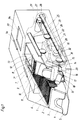
- a storage container 2 for the mixed cards which rises obliquely upwards, is arranged.
- This has a removal opening 3 on its one end side, the end wall 4 having the removal opening 3 defining a slot on its underside with the bottom 5 of the storage container 2, through which the foremost card of the card stack 6 can be withdrawn.
- a card shoe 7 which is made of a relatively heavy material, such as e.g. Steel rests, so that the card shoe 7, due to the inclination of the base 5, has the tendency to slide in the direction of the front end wall 4 which is inclined.
- a mixing container 8 arranged parallel to the latter is provided, which is held so as to be displaceable essentially parallel to the bottom 5 of the storage container 2 and parallel to its longitudinal axis.
- a card shoe 7 ' is also arranged, which ensures the necessary contact pressure of the played card stack 9 on spacer plates 11 arranged in the upper and lower region of the end face of the mixing container 8.
- spacer plates 10, 11 lie against the end face of the wall 12 of the mixing container 8 facing away from the storage container 2 and define with the end face of the wall 13 of the mixing container 8 adjacent to the storage container 2 an ejection gap, the width of which essentially corresponds to the thickness of a card.
- This discharge gap can be seen in FIG. 2 and is designated 41.
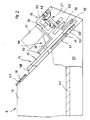
- the foremost card of the card stack 9 can be pushed out into the storage container 2 by means of the ejector 14 through this ejection gap, the card being tilted at the same time.
- This ejector 14 is designed as an angle lever and moves with the free end of its longer one Leg 15 between the two spacer plates 10, 11 and pushes the foremost card of the card deck 9 played through the ejection gap into the storage container 2, the card being tilted at the same time.
- the ejector 14 is driven by a motor 17 held on a support structure 16 formed by a plate via a crank disk 18 and a connecting rod 19.
- the end of the shorter leg 20 of the ejector 14 is thickened and pivotally mounted in the bottom region of the front end of the mixing container 8.
- the mixing container 8 is connected via a connecting piece 21 to a support plate 22 which holds the support structure 16 in its front end region.
- this support plate 22 has three rotatably held rollers 23, which are provided with circumferential grooves 24 and cooperate with guide rails 25 provided with knife edges, which are fastened to the wall of the housing 1 and essentially parallel to the floor 5 of the reservoir 2 run.
- a clamping device 26 is also held, which is clamped to a rotating toothed belt 27, which rotates via a drive pulley 28, which is non-rotatably connected to a motor 29, and a deflection roller 30, which in a at the bottom 31 of the housing 1st attached console 32 is held.
- the mixing container 8 can also be driven by means of a threaded spindle which can be driven by the motor 29 and a nut which is displaceable on the latter but held in a rotationally fixed manner relative to the mixing container 8, it being possible to dispense with the guide rails 25.
- the side walls of the storage container 2 and the mixing container 8 sliding against each other are sufficient to support the frictional moment of the nut.
- the two motors 17 and 29 are controlled by a random number generator, not shown, so that the mixing container 8 constantly oscillates between two end positions of its displacement path and stops between them and the ejector 14 is actuated, so that on a random basis fixed positions of the mixed card stack in the storage container 2 cards are inserted from the mixing container 9.
- the motor 29 is controlled directly by the random generator (not shown) and is stopped at random, after which the motor 17 is activated, after which the mixing container 9 is moved on again. This also results in indirect control of the motor 17 by the random generator.
- the cards are mixed in such a way that, when the mixing container 8 is in the rear end position, the cards played are inserted through an opening 34 of a cover 33 of the housing 1 fastened to the hinges 1 a into the mixing container 8 and the mixer is started .
- the mixing container 8 moves back and forth several times between its two end positions, cards being pushed out at random from the mixing container 8 into the storage container 2, the cards being tilted at the same time.
- the cards in the mixing container 8 can be easily removed after opening the cover 33.
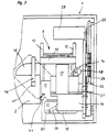
- FIGS. 2 and 3 differs from that according to FIG. 1 in that the supporting structure 16 is formed by a U-profile, the legs 35 of which are aligned essentially parallel to the end faces of the walls 12, 13 of the mixing container 8 are and on the web 36 of the motor 17 is attached. This results in a reduction in the overall length of the mixing container 8 together with the motor 17.
- the crank disk 18 is driven by an angular gear 37, which is formed by bevel gears 49.
- an angle 38 is also attached, one leg 39 of which is provided with a sliding support 40, along which the ejector 14 slides.
- the angle 38 serves as a hold-down and guide for the ejector 14 to ensure that this foremost card of the played card stack 9 is detected in the mixing container and can be pushed out.
- the spacer plate 11 bears against the end face of the bottom 42 of the mixing container 8, the thickened extension 43 of the spacer plate 11, with which it bears against the end face of the bottom 42, as can be seen in FIG. 3, a convex fillet 44 has on the discharge side of the mixing container 8. As indicated by dashed lines, the card slides over this fillet 44 into the storage container 2 or is inserted into the mixed card stack 6. Since the ejector 14 engages with its conical head 48 during the entire swiveling movement in the upper region of the card and in the lower region of the card there is a corresponding frictional resistance due to the pressure by the card shoe 7, the card tilts.
- a cross-sectionally L-shaped carrier 45 is attached to the side wall 13 of the mixing container 8, which carries a depressor 46 which, when the mixing container 8 is moved, counteracts the cards of the mixed card stack 6 in the storage container 2 whose bottom 5 presses.
- This pusher 46 is attached to the carrier 45 and is provided in its front region with a bend 47, which facilitates the passage of cards which protrude upwards. The protruding cards are pressed into the card stack 6 so that they stand up on the bottom 5 of the storage container 2.
Abstract
Description
- Die Erfindung bezieht sich auf einen Kartenmischer mit einem in einem Gehäuse angeordneten Vorratsbehälter zur Aufnahme eines gemischten Kartenstapels, welcher mit einer Entnahmeöffnung für die einzelweise Entnahme von Karten versehen ist, und einem Mischbehälter zur Aufnahme von zu mischenden Karten, der relativ zum Vorratsbehälter verstellbar ist, wobei ein Antrieb für den Mischbehälter und ein Antrieb für einen einzelne Karten aus diesem in den Vorratsbehälter transportierenden Ausstoßer von einem Zufallsgenerator gesteuert sind.
- Ein solcher Kartenmischer wurde z.B. durch die US-PS 4 659 082 bekannt. Bei diesem bekannten Mischer ist der Mischbehälter durch eine antreibbare Trommel gebildet, die radial verlaufende Schächte zur Aufnahme je einer Karte aufweist. Dabei ist eine Eingabestation zur Aufnahme eines Stapels gespielter Karten vorgesehen, über die das Beschicken der einzelnen Schächte der Trommel erfolgt. Der Vorratsbehälter für die gemischten Karten wird von der Trommel beschickt, wobei aufgrund der Ansteuerung eines Kartenauswerfers die einzelnen Karten nach einem Zufallsprinzip in den Vorratsbehälter ausgeschoben werden.
- Mit einem solchen Kartenmischer wird ein sehr hoher Durchmischungsgrad erreicht, wobei eine Voraussehbarkeit der Kartenfolge im gemischten Kartenstapel auch bei Anwendung von Zählverfahren praktisch nicht gegeben ist.
- Der Nachteil der bekannten Lösung liegt im großen Platzbedarf des Kartenmischers, welcher durch die Trommel verursacht wird.
- Außerdem ist im Falle einer Störung die Entnahme der Karten aus der Trommel sehr umständlich und aufwendig.
- Ziel der Erfindung ist es, diese Nachteile zu vermeiden und einen Kartenmischer der eingangs erwähnten Art vorzuschlagen, der sich durch einen geringen Platzbedarf auszeichnet und bei dem im Falle einer Störung die Karten leicht entnommen und das Spiel durch händisches Mischen fortgesetzt werden kann.
- Erfindungsgemäß wird dies dadurch erreicht, daß der Mischbehälter neben dem Vorratsbehälter angeordnet und parallel zu diesem bewegbar ist und der Ausstoßer Karten aus dem Mischbehälter in den Vorratsbehälter überführt, wobei die zu mischenden Karten in einer Endstellung des Mischbehälters durch eine Öffnung des Gehäuses hindurch in diesen eingebbar sind.
- Auf diese Weise ergibt sich ein sehr kompakter Aufbau des Kartenmischers. Durch das Überführen einzelner Karten aus dem Mischbehälter in den Vorratsbehälter nach einem Zufallsprinzip ergibt sich auch ein sehr hoher Durchmischungsgrad, wobei eine Vorhersehbarkeit der Kartenfolge im gemischten Kartenstapel auch bei Anwendung von Zählverfahren praktisch nicht gegeben ist.
- Außerdem ergibt sich durch den erfindungsgemäßen Aufbau der Vorteil, daß bei einer Störung des Kartenmischers ohne weiteres mit dem gleichen Kartenpaket weitergespielt werden kann, was bei einem Casinobetrieb einen sehr wesentlichen Vorteil darstellt. Im Falle einer Störung kann das gespielte Kartenpaket aus dem Mischbehälter entnommen und händisch gemischt werden, wonach es, wie bei einem Spiel ohne automatischen Kartenmischer üblich, in den Vorratsbehälter eingesteckt und die Karten aus diesem einzelweise über dessen Entnahmeöffnung entnommen werden können. Auf diese Weise können im Falle einer Störung des Kartenmischers unangenehme Debatten mit den Spielern bei Verwendung eines neuen Kartenstapels, wie es bei der bekannten Lösung erforderlich wäre, vermieden werden.
- Nach einem weiteren Merkmal der Erfindung kann vorgesehen sein, daß der Mischbehälter an seiner einen Stirnseite in seinem oberen und unteren Bereich Distanzplatten aufweist, die mit der Stirnseite einer Seitenwand des Mischbehälters an der Ausstoßseite für die zu mischenden Karten einen Ausstoßspalt definieren, der im wesentlichen der Dicke einer Karte entspricht und zwischen diesen Platten der Ausstoßer bewegbar ist, der über die Stirnseiten der die Karte seitlich führenden Seitenwände des Mischbehälters hinwegstreicht.
- Durch diese Maßnahmen ist ein sicheres und problemloses Überführen der einzelnen Karten aus dem Mischbehälter in den Vorratsbehälter sichergestellt. So ist dadurch gewährleistet, daß stets nur eine Karte durch den Ausstoßschlitz aus dem Mischbehälter ausgeschoben und in den im Vorratsbehälter befindlichen Kartenstapel eingeschoben wird.
- Nach einem weiteren Merkmal kann vorgesehen sein, daß die untere Distanzplatte an der Ausstoßseite einen den Ausstoßspalt in der Höhe des Bodens des Mischbehälters begrenzenden Ansatz aufweist, der in der Ebene der Stirnseite der ausstoßseitigen Seitenwand des Mischbehälters eine konvexe Ausrundung aufweist, über die die auszustoßende Karte in den Vorratsbehälter gleitet.
- Dadurch wird ein einfaches Ausschieben der einzelnen Karten entlang eines definierten Weges sichergestellt.
- In diesem Zusammenhang kann weiters vorgesehen sein, daß der Mischbehälter eine der Breite der Karten entsprechende Breite und der Vorratsbehälter eine der Länge der Karten entsprechende Breite aufweist.
- Dies ermöglicht einerseits ein einfaches Eingeben der gespielten Karten in den Mischbehälter, da die Karten stehend eingegeben werden können und ein einfaches Entnehmen der gemischten Karten über die Entnahmeöffnung des Vorratsbehälters, da diese Karten liegend im Vorratsbehälter gestapelt sind.
- Dabei ist es zweckmäßig, wenn der Ausstoßer im oberen Endbereich einer jeden Karte an dieser ansetzt, wodurch diese im Zuge des Ausstoßens aus dem Mischbehälter gleichzeitig gekippt wird.
- Dabei kann weiters vorgesehen sein, daß der Ausstoßer als Winkelhebel ausgebildet ist, der im Endbereich eines seiner Schenkel, vorzugsweise seines kürzeren Schenkels, schwenkbar im Bodenbereich der Stirnseite nahe der dem Vorratsbehälter benachbarten Seitenwand des Mischbehälters gelagert und gegebenenfalls über einen Kurbeltrieb antreibbar ist.
- Auf diese Weise ist sichergestellt, daß der Ausstoßer stets im oberen Bereich der auszustoßenden Karte an dieser angreift, wodurch diese während des Ausstoßens sicher gekippt wird, wobei sich durch die Anordnung eines Kurbeltriebes der Antriebsmotor stets nur in einer Richtung zu drehen braucht und daher einsprechend einfach aufgebaut sein kann und sich auch eine einfache Ansteuerung dieses Motors ergibt.
- Nach einem weiteren Merkmal der Erfindung kann vorgesehen sein, daß der Mischbehälter mit einer seitlich desselben angeordneten Tragplatte verbunden ist, an der eine vor einer schräg nach hinten geneigten Stirnseite des Mischbehälters ragende Tragkonstrution befestigt ist, in der der Antrieb des Ausstoßers gehalten ist, wobei der Motor zum Antrieb des Ausstoßers vorzugsweise parallel zu dieser Stirnseite des Mischbehälters ausgerichtet ist und über ein Winkelgetriebe eine mit dem Ausstoßer über ein Pleuel verbundene Kurbelscheibe antreibt, welches Pleuel an dem Ausstoßer angreift.
- Auf diese Weise ergibt sich eine sehr einfache Konstruktion, wobei durch Ausrichtung des Motors für den Ausstoßer parallel zu der einen Stirnseite des Mischbehälters eine Verminderung der Baulänge des Kartenmischers ermöglicht wird.
- Weiters kann vorgesehen sein, daß die Tragplatte mit einer Klemmeinrichtung versehen ist, die an einem umlaufenden Zahnriemen festgeklemmt ist, der über eine von einem Motor angetriebene Scheibe und eine Umlenkrolle geführt ist, wobei das in der Klemmeinrichtung gehaltene Trum des Zahnriemens im wesentlichen parallel zu Führungen verläuft, die mit der Tragplatte zusammenwirken.
- Auf diese Weise ergibt sich eine sehr sichere Mitnahme des Mischbehälters, sodaß auf eine separate Überwachung der Lage des Mischbehälters relativ zum Vorratsbehälter verzichtet werden kann, insbesondere, wenn für den Antrieb des Mischbehälters ein Schrittschaltmotor verwendet wird.
- Die Erfindung wird nun anhand der Zeichnung näher erläutert. Dabei zeigen:
- Fig. 1 schematisch eine axonometrische Darstellung einer ersten Ausführungsform eines erfindungsgemäßen Kartenmischers,
- Fig. 2 eine Ansicht der Stirnseite eines Mischbehälters einer weiteren Ausführungsform eines erfindungsgemäßen Kartenmischers und
- Fig. 3 eine Seitenansicht der Frontpartie des Mischbehälters nach der Fig. 2.
- Im Gehäuse 1 des Kartenmischers nach der Fig. 1 ist ein schräg nach oben ansteigender Vorratsbehälter 2 für die gemischten Karten angeordnet. Dieser weist an seiner einen Stirnseite eine Entnahmeöffnung 3 auf, wobei die die Entnahmeöffnung 3 aufweisende Stirnwand 4 an ihrer Unterseite mit dem Boden 5 des Vorratsbehälters 2 einen Schlitz definiert, durch den die vorderste Karte des Kartenstapels 6 abgezogen werden kann.
- Für die Sicherstellung eines entsprechenden Anpreßdruckes des Kartenstapels 6 an der Innenseite der Stirnwand 4 ist ein Kartenschuh 7 vorgesehen, der auf einer in seinem Inneren angeordneten in dessen Seitenwänden drehbar gehaltenen Walze aus einem relativ schwerem Material, wie z.B. Stahl aufliegt, sodaß der Kartenschuh 7 aufgrund der Neigung des Bodens 5 das Bestreben hat in Richtung zur vorderen geneigt angeordneten Stirnwand 4 zu rutschen.
- Neben dem Vorratsbehälter 2 ist ein parallel zu diesem angeordneter Mischbehälter 8 vorgesehen, der im wesentlichen parallel zum Boden 5 des Vorratsbehälters 2 und parallel zu dessen Längsachse verschiebbar gehalten ist. In diesem Mischbehälter 8, der mit den gespielten Karten beladen wird, ist ebenfalls ein Kartenschuh 7' angeordnet, der für den nötigen Anpreßdruck des gespielten Kartenstapels 9 an im oberen und unteren Bereich der Stirnseite des Mischbehälters 8 angeordneten Distanzplatten 11 sorgt. Diese Distanzplatten 10, 11 liegen an der Stirnseite der vom Vorratsbehälter 2 abgekehrten Wand 12 des Mischbehälters 8 an und definieren mit der Sirnseite der dem Vorratsbehälter 2 benachbarten Wand 13 des Mischbehälters 8 einen Ausstoßspalt, dessen Breite im wesentlichen der Dicke einer Karte entspricht. Dieser Ausstoßspalt ist aus der Fig. 2 ersichtlich und mit 41 bezeichnet.
- Durch diesen Ausstoßspalt hindurch ist die vorderste Karte des Kartenstapels 9 mittels des Ausstoßers 14 in den Vorratsbehälter 2 ausschiebbar, wobei die Karte gleichzeitig gekippt wird. Dieser Ausstoßer 14 ist als Winkelhebel ausgebildet und bewegt sich mit dem freien Ende seines längeren Schenkels 15 zwischen den beiden Distanzplatten 10, 11 und schiebt dabei die vorderste Karte des gespielten Kartenstapels 9 durch den Ausstoßspalt in den Vorratsbehälter 2 aus, wobei die Karte gleichzeitig gekippt wird.
- Der Ausstoßer 14 wird von einem an einer durch eine Platte gebildeten Tragkonstruktion 16 gehaltenen Motor 17 über eine Kurbelscheibe 18 und ein Pleuel 19 angetrieben. Dabei ist das Ende des kürzeren Schenkels 20 des Ausstoßers 14 verdickt und im Bodenbereich des vorderen Endes des Mischbehälters 8 schwenkbar gelagert.
- Der Mischbehälter 8 ist über ein Verbindungsstück 21 mit einer Tragplatte 22 verbunden, die in ihrem vorderen Endbereich die Tragkonstruktion 16 hält. Diese Tragplatte 22 weist bei der Ausführungsform nach der Fig. 1 drei drehbar gehaltene Rollen 23 auf, die mit umlaufenden Rillen 24 versehen sind und mit mit Messerkanten versehenen Führungsschienen 25 zusammenwirken, die an der Wand des Gehäuses 1 befestigt sind und im wesentlichen parallel zum Boden 5 des Vorratsbehälters 2 verlaufen.
- An der Tragplatte 22 ist weiters eine Klemmeinrichtung 26 gehalten, die an einem umlaufenden Zahnriemen 27 festgeklemmt ist, der über eine Antriebsscheibe 28, die mit einem Motor 29 drehfest verbunden ist, und eine Umlenkrolle 30 umläuft, die in einer am Boden 31 des Gehäuses 1 befestigten Konsole 32 gehalten ist.
- Grundsätzlich kann der Antrieb des Mischbehälters 8 auch mittels einer Gewindespindel, die vom Motor 29 antreibbar ist, und einer auf dieser verschiebbar jedoch gegenüber dem Mischbehälter 8 drehfest gehaltenen Mutter erfolgen, wobei auf die Führungsschienen 25 verzichtet werden kann. Zur Abstützung des Reibungsmomentes der Mutter genügen die aneinander gleitenden Seitenwände des Vorratsbehälters 2 und des Mischbehälters 8.
- Die beiden Motore 17 und 29 werden von einem nicht dargestellten Zufallsgenerator gesteuert, sodaß der Mischbehälter 8 ständig zwischen zwei Endstellungen seines Verschiebeweges pendelt und zwischen diesen anhält und der Ausstoßer 14 betätigt wird, sodaß an nach einem Zufallsprinzip festgelegten Stellen des im Vorratsbehälter 2 befindlichen gemischten Kartenstapels Karten aus dem Mischbehälter 9 eingeschoben werden. Dabei kann vorgesehen sein, daß der Motor 29 direkt von dem nicht dargestellten Zufallsgenerator gesteuert ist und nach dem Zufallsprinzip angehalten wird, wonach der Motor 17 aktiviert wird, wonach der Mischbehälter 9 wieder weiterbewegt wird. Dadurch ergibt sich eine indirekte Steuerung auch des Motors 17 durch den Zufallsgenerator.
- Dadurch ist die Kartenfolge im gemischten Kartenstapel 6 auch bei Verwendung von Zählmethoden nicht vorhersehbar.
- Das Mischen von Karten erfolgt dabei in der Weise, daß bei in der hinteren Endstellung befindlichem Mischbehälter 8 die gespielten Karten durch eine Öffnung 34 eines an den Scharnieren la befestigten Deckels 33 des Gehäuses 1 hindurch stehend in den Mischbehälter 8 eingesteckt werden und der Mischer gestartet wird. Dadurch fährt der Mischbehälter 8 mehrmals zwischen seinen beiden Endstellungen hin und her, wobei an nach dem Zufallsprinzip ausgewählten Stellen Karten aus dem Mischbehälter 8 in den Vorratsbehälter 2 ausgeschoben werden, wobei die Karten gleichzeitig gekippt werden. Im Falle eines Fehlers des Kartenmischers können die im Mischbehälter 8 befindlichen Karten nach dem Öffnen des Deckels 33 leicht entnommen werden.
- Die Ausführungsform nach den Fig. 2 und 3 unterscheidet sich von jener nach der Fig. 1 dadurch, daß die Tragkonstruktion 16 durch ein U-Profil gebildet ist, dessen Schenkel 35 im wesentlichen parallel zu den Stirnseiten der Wände 12, 13 des Mischbehälters 8 ausgerichtet sind und an dessen Steg 36 der Motor 17 befestigt ist. Dadurch wird eine Verringerung der Baulänge des Mischbehälters 8 samt Motor 17 erreicht. Der Antrieb der Kurbelscheibe 18 erfolgt dabei über ein Winkelgetriebe 37, das durch Kegelzahnräder 49 gebildet ist.
- Auf dem Steg 36 der Tragkonstruktion 16 ist weiters ein Winkel 38 befestigt, dessen einer Schenkel 39 mit einer Gleitauflage 40 versehen ist, an der der Ausstoßer 14 entlang gleitet. Dabei dient der Winkel 38 als Niederhalter und Führung für den Ausstoßer 14, um sicherzustellen, daß dieser die vorderste Karte des gespielten Kartenstapels 9 im Mischbehälter erfaßt und ausschieben kann.
- Aus der Fig. 2 ist auch sehr deutlich der durch die Distanzplatten 10, 11 und der Stirnseite der Wand 13 des Mischbehälters 8 definierte Ausstoßspalt 41 zu erkennen, durch den ein Karte aus dem Mischbehälter 8 in den Vorratsbehälter ausgeschoben werden kann.
- Die Distanzplatte 11 liegt an der Stirnseite des Bodens 42 des Mischbehälters 8 an, wobei der verdickte Ansatz 43 der Distanzplatte 11, mit dem diese, wie aus der Fig. 3 zu ersehen ist, an der Stirnseite des Bodens 42 anliegt, eine konvexe Ausrundung 44 an der Ausstoßseite des Mischbehälter 8 aufweist. Über diese Ausrundung 44 gleitet, wie strichliert angedeutet ist, die Karte in den Vorratsbehälter 2, bzw. wird in den gemischten Kartenstapel 6 eingeschoben. Da der Ausstoßer 14 mit seinem konischen Kopf 48 während der gesamten Schwenkbewegung im oberen Bereich der Karte an dieser angreift und im unteren Bereich der Karte aufgrund der Anpressung durch den Kartenschuh 7 ein entsprechender Reibungswiderstand gegeben ist, kommt es zum Kippen der Karte.
- Bei der Ausführungsform nach den Fig. 2 und 3 ist an der Seitenwand 13 des Mischbehälters 8 ein im Querschnitt L-förmiger Träger 45 angebracht, der einen Niederdrücker 46 trägt, der beim Verschieben des Mischbehälters 8 die Karten des gemischten Kartenstapels 6 im Vorratsbehälter 2 gegen dessen Boden 5 drückt. Dieser Niederdrücker 46 ist auf dem Träger 45 aufgesteckt und ist in seinem vorderen Bereich mit einer Aufbiegung 47 versehen, die ein Uberfahren nach oben herausragender Karten erleichtert. Dabei werden die vorragenden Karten in den Kartenstapel 6 hineingedrückt, sodaß diese auf dem Boden 5 des Vorratsbehälters 2 aufstehen.
Claims (7)
- Kartenmischer mit einem in einem Gehäuse angeordneten Vorratsbehälter zur Aufnahme eines gemischten Kartenstapels, welcher mit einer Entnahmeöffnung für die einzelweise Entnahme von Karten versehen ist, und einem Mischbehälter zur Aufnahme von zu mischenden Karten, der relativ zum Vorratsbehälter verstellbar ist, wobei ein Antrieb für den Mischbehälter und ein Antrieb für einen einzelne Karten aus diesem in den Vorratsbehälter transportierenden Ausstoßer von einem Zufallsgenerator gesteuert sind, dadurch gekennzeichnet, daß der Mischbehälter (8) neben dem Vorratsbehälter (2) angeordnet und parallel zu diesem bewegbar ist und der Ausstoßer (14) Karten aus dem Mischbehälter (8) in den Vorratsbehälter (2) überführt, wobei die zu mischenden Karten in einer Endstellung des Mischbehälters (8) durch eine Öffnung (34) des Gehäuses (1) hindurch in diesen eingebbar sind.
- Kartenmischer nach Anspruch 1, dadurch gekennzeichnet, daß der Mischbehälter (8) an seiner einen Stirnseite in seinem oberen und unteren Bereich Distanzplatten (10, 11) aufweist, die mit der Stirnseite einer Seitenwand (13) des Mischbehälters (8) an der Ausstoßseite für die zu mischenden Karten einen Ausstoßspalt (41) definieren, der im wesentlichen der Dicke einer Karte entspricht und zwischen diesen Platten (10, 11) der Ausstoßer (14) bewegbar ist, der über die Stirnseiten der die Karten seitlich führenden Seitenwände (10, 11) des Mischbehälters (8) hinwegstreicht.
- Kartenmischer nach Anspruch 1 oder 2, dadurch gekennzeichnet, daß die untere Distanzplatte (11) an der Ausstoßseite einen den Ausstoßspalt (41) in der Höhe des Bodens (42) des Mischbehälters (8) begrenzenden Ansatz (43) aufweist, der in der Ebene der Stirnseite der ausstoßseitigen Seitenwand (13) des Mischbehälters (8) eine konvexe Ausrundung (44) aufweist, über die die auszustoßende Karte in den Vorratsbehälter (2) gleitet.
- Kartenmischer nach einem der Ansprüche 1 bis 3, dadurch gekennzeichnet, daß der Ausstoßer (14) als Winkelhebel ausgebildet ist, der im Endbereich eines seiner Schenkel, vorzugsweise seines kürzeren Schenkels (20), schwenkbar im Bodenbereich der Stirnseite nahe der dem Vorratsbehälter (2) benachbarten Seitenwand (13) des Mischbehälters (8) gelagert und gegebenenfalls über einen Kurbeltrieb (18, 19) antreibbar ist.
- Kartenmischer nach einem der Ansprüche 1 bis 4, dadurch gekennzeichnet, daß der Mischbehälter (8) mit einer seitlich desselben angeordneten Tragplatte (22) verbunden ist, an der eine vor einer schräg nach hinten geneigten Stirnseite (13) des Mischbehälters (8) ragende Tragkonstrution (16) befestigt ist, in der der Antrieb des Ausstoßers (14) gehalten ist, wobei der Motor (17) zum Antrieb des Ausstoßers (14) vorzugsweise parallel zu dieser Stirnseite des Mischbehälters (8) ausgerichtet ist und über ein Winkelgetriebe (37) eine mit dem Ausstoßer (14) über ein Pleuel (19) verbundene Kurbelscheibe (18) antreibt, welches Pleuel an dem Ausstoßer (14) angreift.
- Kartenmischer nach einem der Ansprüche 1 bis 5, dadurch gekennzeichnet, daß die Tragplatte (22) mit einer von dieser an der dem Mischbehälter (8) abgekehrten Seite abstehenden Klemmeinrichtung (26) versehen ist, die an einem seitlich der Tragplatte (22) umlaufenden Zahnriemen (27) festgeklemmt ist, der über eine von einem Motor (29) angetriebene Scheibe (28) und eine Umlenkrolle (30) geführt ist, wobei das in der Klemmeinrichtung (26) gehaltene Trum des Zahnriemens (27) im wesentlichen parallel zu Führungen (25) verläuft, die mit der Tragplatte (22) zusammenwirken.
- Kartenmischer nach einem der Ansprüche 1 bis 6, dadurch gekennzeichnet, daß der Mischbehälter (8) eine der Breite der Karten entsprechende Breite und der Vorratsbehälter (2) eine der Länge der Karten entsprechende Breite aufweist.
Applications Claiming Priority (2)
| Application Number | Priority Date | Filing Date | Title |
|---|---|---|---|
| AT2011/92 | 1992-10-13 | ||
| AT0201192A AT401887B (de) | 1992-10-13 | 1992-10-13 | Kartenmischer |
Publications (3)
| Publication Number | Publication Date |
|---|---|
| EP0597818A2 true EP0597818A2 (de) | 1994-05-18 |
| EP0597818A3 EP0597818A3 (de) | 1995-05-17 |
| EP0597818B1 EP0597818B1 (de) | 1998-08-19 |
Family
ID=3525914
Family Applications (1)
| Application Number | Title | Priority Date | Filing Date |
|---|---|---|---|
| EP93890177A Expired - Lifetime EP0597818B1 (de) | 1992-10-13 | 1993-09-09 | Kartenmischer |
Country Status (8)
| Country | Link |
|---|---|
| US (1) | US5382024A (de) |
| EP (1) | EP0597818B1 (de) |
| AT (2) | AT401887B (de) |
| CA (1) | CA2108196C (de) |
| DE (1) | DE59308886D1 (de) |
| DK (1) | DK0597818T3 (de) |
| ES (1) | ES2118929T3 (de) |
| ZA (1) | ZA936958B (de) |
Families Citing this family (128)
| Publication number | Priority date | Publication date | Assignee | Title |
|---|---|---|---|---|
| US5676372A (en) * | 1994-04-18 | 1997-10-14 | Casinovations, Inc. | Playing card shuffler |
| US7584962B2 (en) * | 1994-08-09 | 2009-09-08 | Shuffle Master, Inc. | Card shuffler with jam recovery and display |
| US5695189A (en) | 1994-08-09 | 1997-12-09 | Shuffle Master, Inc. | Apparatus and method for automatically cutting and shuffling playing cards |
| US20020063389A1 (en) * | 1994-08-09 | 2002-05-30 | Breeding John G. | Card shuffler with sequential card feeding module and method of delivering groups of cards |
| US5683085A (en) * | 1994-08-15 | 1997-11-04 | Johnson; Rodney George | Card handling apparatus |
| AU711416B2 (en) * | 1994-08-15 | 1999-10-14 | Gaming Products Limited | Card handling apparatus |
| US5944310A (en) * | 1995-06-06 | 1999-08-31 | Gaming Products Pty Ltd | Card handling apparatus |
| USRE46505E1 (en) | 1995-10-17 | 2017-08-08 | Bally Gaming, Inc. | System including card game dispensing shoe and method |
| US5722893A (en) * | 1995-10-17 | 1998-03-03 | Smart Shoes, Inc. | Card dispensing shoe with scanner |
| US6039650A (en) * | 1995-10-17 | 2000-03-21 | Smart Shoes, Inc. | Card dispensing shoe with scanner apparatus, system and method therefor |
| US7699694B2 (en) * | 1995-10-17 | 2010-04-20 | Shuffle Master, Inc. | System including card game dispensing shoe and method |
| US5685543A (en) * | 1996-05-28 | 1997-11-11 | Garner; Lee B. | Playing card holder and dispenser |
| US5692748A (en) * | 1996-09-26 | 1997-12-02 | Paulson Gaming Supplies, Inc., | Card shuffling device and method |
| US6676127B2 (en) * | 1997-03-13 | 2004-01-13 | Shuffle Master, Inc. | Collating and sorting apparatus |
| CA2306226A1 (en) * | 1997-10-14 | 1999-04-22 | Shane Long | A method for handling of cards in a dealer shoe, and a dealer shoe |
| US6149154A (en) | 1998-04-15 | 2000-11-21 | Shuffle Master Gaming | Device and method for forming hands of randomly arranged cards |
| CA2364413C (en) * | 1998-04-15 | 2012-03-20 | Shuffle Master, Inc. | Device and method for continuously shuffling and monitoring cards |
| US20020163125A1 (en) * | 1998-04-15 | 2002-11-07 | Shuffle Master, Inc. | Device and method for continuously shuffling and monitoring cards for specialty games |
| US6254096B1 (en) | 1998-04-15 | 2001-07-03 | Shuffle Master, Inc. | Device and method for continuously shuffling cards |
| US7255344B2 (en) | 1998-04-15 | 2007-08-14 | Shuffle Master, Inc. | Device and method for continuously shuffling and monitoring cards |
| US6655684B2 (en) | 1998-04-15 | 2003-12-02 | Shuffle Master, Inc. | Device and method for forming and delivering hands from randomly arranged decks of playing cards |
| USD432588S (en) * | 1999-08-30 | 2000-10-24 | Shuffle Master, Inc. | Card shuffling apparatus |
| US6250632B1 (en) | 1999-11-23 | 2001-06-26 | James Albrecht | Automatic card sorter |
| US8490973B2 (en) | 2004-10-04 | 2013-07-23 | Shfl Entertainment, Inc. | Card reading shoe with card stop feature and systems utilizing the same |
| US8511684B2 (en) | 2004-10-04 | 2013-08-20 | Shfl Entertainment, Inc. | Card-reading shoe with inventory correction feature and methods of correcting inventory |
| US8590896B2 (en) | 2000-04-12 | 2013-11-26 | Shuffle Master Gmbh & Co Kg | Card-handling devices and systems |
| US7946586B2 (en) * | 2000-04-12 | 2011-05-24 | Shuffle Master Gmbh & Co Kg | Swivel mounted card handling device |
| US6817466B2 (en) * | 2000-11-09 | 2004-11-16 | Honeywell International, Inc. | Apparatus for manufacturing filter cartridges, and method of using same |
| US7390256B2 (en) * | 2001-06-08 | 2008-06-24 | Arl, Inc. | Method, apparatus and article for random sequence generation and playing card distribution |
| US7677565B2 (en) | 2001-09-28 | 2010-03-16 | Shuffle Master, Inc | Card shuffler with card rank and value reading capability |
| US8038521B2 (en) * | 2001-09-28 | 2011-10-18 | Shuffle Master, Inc. | Card shuffling apparatus with automatic card size calibration during shuffling |
| US7753373B2 (en) | 2001-09-28 | 2010-07-13 | Shuffle Master, Inc. | Multiple mode card shuffler and card reading device |
| US8011661B2 (en) | 2001-09-28 | 2011-09-06 | Shuffle Master, Inc. | Shuffler with shuffling completion indicator |
| CA2461726C (en) * | 2001-09-28 | 2015-06-09 | Shuffle Master, Inc. | Card shuffling apparatus with automatic card size calibration |
| US6651981B2 (en) | 2001-09-28 | 2003-11-25 | Shuffle Master, Inc. | Card shuffling apparatus with integral card delivery |
| US8616552B2 (en) | 2001-09-28 | 2013-12-31 | Shfl Entertainment, Inc. | Methods and apparatuses for an automatic card handling device and communication networks including same |
| US8337296B2 (en) | 2001-09-28 | 2012-12-25 | SHFL entertaiment, Inc. | Method and apparatus for using upstream communication in a card shuffler |
| AT5678U1 (de) * | 2001-10-19 | 2002-10-25 | Card Casinos Austria Res & Dev | Kartenmischer |
| US8262090B2 (en) * | 2001-12-13 | 2012-09-11 | The United States Playing Card Company | Method, apparatus and article for random sequence generation and playing card distribution |
| US6886829B2 (en) * | 2002-02-08 | 2005-05-03 | Vendingdata Corporation | Image capturing card shuffler |
| PL352958A1 (en) * | 2002-03-22 | 2003-10-06 | Wiesław Wacławek | Appliance for issuing cards, particularly business cards |
| JP4056062B2 (ja) * | 2003-05-29 | 2008-03-05 | アルゼ株式会社 | 記録媒体取扱装置 |
| US20050113166A1 (en) * | 2003-07-17 | 2005-05-26 | Shuffle Master, Inc. | Discard rack with card reader for playing cards |
| CA2541377C (en) * | 2003-10-08 | 2017-03-21 | Arl, Inc. | Method, apparatus and article for computational sequence generation and playing card distribution |
| US7258341B2 (en) | 2003-10-21 | 2007-08-21 | Alireza Pirouzkhah | Variable point generation craps game |
| US7510194B2 (en) * | 2004-06-30 | 2009-03-31 | Bally Gaming, Inc. | Playing cards with separable components |
| US20060066048A1 (en) * | 2004-09-14 | 2006-03-30 | Shuffle Master, Inc. | Magnetic jam detection in a card shuffler |
| US7766332B2 (en) | 2006-07-05 | 2010-08-03 | Shuffle Master, Inc. | Card handling devices and methods of using the same |
| AU2005326902A1 (en) | 2005-02-07 | 2006-08-10 | Telefonaktiebolaget Lm Ericsson (Publ). | Plain old telephony equivalent services supported via unlicensed mobile access |
| US8074987B2 (en) * | 2005-02-10 | 2011-12-13 | Bally Gaming, Inc. | Systems and methods for processing playing cards collected from a gaming table |
| US7764836B2 (en) * | 2005-06-13 | 2010-07-27 | Shuffle Master, Inc. | Card shuffler with card rank and value reading capability using CMOS sensor |
| US8313365B2 (en) * | 2005-07-01 | 2012-11-20 | Gioia Systems, Llc | Detecting duplicate collections of virtual playing instruments |
| US7766331B2 (en) * | 2005-07-01 | 2010-08-03 | Gioia Systems, Llc | Method and device for physically randomizing a plurality of playing instruments in absence of a random number generator |
| US7591728B2 (en) * | 2005-07-01 | 2009-09-22 | Gioia Systems, Llc | Online gaming system configured for remote user interaction |
| US8113932B2 (en) * | 2005-07-01 | 2012-02-14 | Gioia Systems, Llc | Method and computer readable medium relating to creating child virtual decks from a parent virtual deck |
| US20070057454A1 (en) * | 2005-09-12 | 2007-03-15 | Bally Gaming, Inc. | System and method to handle playing cards, employing manual movable cover |
| US8550464B2 (en) | 2005-09-12 | 2013-10-08 | Bally Gaming, Inc. | Systems, methods and articles to facilitate playing card games with selectable odds |
| US20070057453A1 (en) * | 2005-09-12 | 2007-03-15 | Bally Gaming, Inc. | System and method to handle playing cards, employing manual movable cover |
| US8342932B2 (en) * | 2005-09-12 | 2013-01-01 | Bally Gaming, Inc. | Systems, methods and articles to facilitate playing card games with intermediary playing card receiver |
| US8342533B2 (en) * | 2005-09-12 | 2013-01-01 | Bally Gaming, Inc. | Systems, methods and articles to facilitate playing card games with multi-compartment playing card receivers |
| US7900923B2 (en) * | 2006-02-21 | 2011-03-08 | Shuffle Tech International Llc | Apparatus and method for automatically shuffling cards |
| US7971881B2 (en) * | 2006-02-21 | 2011-07-05 | Shuffle Tech International Llc | Apparatus and method for automatically shuffling cards |
| US20070216092A1 (en) * | 2006-03-15 | 2007-09-20 | Bally Gaming, Inc. | Card shoe for holding playing cards |
| US7556266B2 (en) | 2006-03-24 | 2009-07-07 | Shuffle Master Gmbh & Co Kg | Card shuffler with gravity feed system for playing cards |
| US8366109B2 (en) | 2006-04-12 | 2013-02-05 | Bally Gaming, Inc. | System and method to handle playing cards, employing elevator mechanism |
| US7523937B2 (en) * | 2006-04-18 | 2009-04-28 | Bally Gaming, Inc. | Device for use in playing card handling system |
| US8636285B2 (en) * | 2006-05-03 | 2014-01-28 | Shfl Entertainment, Inc. | Ergonomic card delivery shoe |
| US8419016B2 (en) | 2006-05-17 | 2013-04-16 | Shfl Entertainment, Inc. | Playing card delivery for games with multiple dealing rounds |
| US7448626B2 (en) * | 2006-05-23 | 2008-11-11 | Bally Gaming, Inc. | Systems, methods and articles to facilitate playing card games |
| US8038153B2 (en) * | 2006-05-23 | 2011-10-18 | Bally Gaming, Inc. | Systems, methods and articles to facilitate playing card games |
| US8100753B2 (en) * | 2006-05-23 | 2012-01-24 | Bally Gaming, Inc. | Systems, methods and articles to facilitate playing card games with selectable odds |
| US7510186B2 (en) * | 2006-05-23 | 2009-03-31 | Bally Gaming, Inc. | Systems, methods and articles to facilitate delivery of playing cards |
| US8579289B2 (en) * | 2006-05-31 | 2013-11-12 | Shfl Entertainment, Inc. | Automatic system and methods for accurate card handling |
| US8342525B2 (en) | 2006-07-05 | 2013-01-01 | Shfl Entertainment, Inc. | Card shuffler with adjacent card infeed and card output compartments |
| US8353513B2 (en) | 2006-05-31 | 2013-01-15 | Shfl Entertainment, Inc. | Card weight for gravity feed input for playing card shuffler |
| US8052519B2 (en) * | 2006-06-08 | 2011-11-08 | Bally Gaming, Inc. | Systems, methods and articles to facilitate lockout of selectable odds/advantage in playing card games |
| US8998692B2 (en) * | 2006-06-21 | 2015-04-07 | Bally Gaming, Inc. | Systems, methods and articles to facilitate delivery of sets or packets of playing cards |
| US8070574B2 (en) | 2007-06-06 | 2011-12-06 | Shuffle Master, Inc. | Apparatus, system, method, and computer-readable medium for casino card handling with multiple hand recall feature |
| US9101820B2 (en) * | 2006-11-09 | 2015-08-11 | Bally Gaming, Inc. | System, method and apparatus to produce decks for and operate games played with playing cards |
| US8919775B2 (en) | 2006-11-10 | 2014-12-30 | Bally Gaming, Inc. | System for billing usage of an automatic card handling device |
| US7854430B2 (en) * | 2007-05-24 | 2010-12-21 | Shuffle Tech International Llc | Card shuffling device and method |
| US8475252B2 (en) * | 2007-05-30 | 2013-07-02 | Shfl Entertainment, Inc. | Multi-player games with individual player decks |
| CN102307633A (zh) * | 2008-04-09 | 2012-01-04 | Igt公司 | 用于游戏桌的牌盒安全的系统和方法 |
| US8308562B2 (en) * | 2008-04-29 | 2012-11-13 | Bally Gaming, Inc. | Biofeedback for a gaming device, such as an electronic gaming machine (EGM) |
| US8613655B2 (en) * | 2008-04-30 | 2013-12-24 | Bally Gaming, Inc. | Facilitating group play with multiple game devices |
| US9092944B2 (en) * | 2008-04-30 | 2015-07-28 | Bally Gaming, Inc. | Coordinating group play events for multiple game devices |
| WO2009155047A2 (en) | 2008-05-30 | 2009-12-23 | Bally Gaming, Inc. | Web pages for gaming devices |
| US7740244B2 (en) * | 2008-06-05 | 2010-06-22 | Taiwan Fulgent Enterprise Co., Ltd. | Card cartridge for a shuffling machine |
| US8967621B2 (en) | 2009-04-07 | 2015-03-03 | Bally Gaming, Inc. | Card shuffling apparatuses and related methods |
| US7988152B2 (en) | 2009-04-07 | 2011-08-02 | Shuffle Master, Inc. | Playing card shuffler |
| US20110012303A1 (en) * | 2009-07-14 | 2011-01-20 | Fairplay, Inc. | Shuffler for playing cards |
| US7874559B1 (en) * | 2009-08-10 | 2011-01-25 | Tzu-Hsiang Tseng | Playing card dispensing and opening system |
| US8800993B2 (en) | 2010-10-14 | 2014-08-12 | Shuffle Master Gmbh & Co Kg | Card handling systems, devices for use in card handling systems and related methods |
| US8348278B2 (en) * | 2011-01-03 | 2013-01-08 | Tzu-Hsiang Tseng | Playing card dispensing and opening system |
| US8657287B2 (en) | 2011-06-03 | 2014-02-25 | The United States Playing Card Company | Intelligent table game system |
| KR20140036270A (ko) * | 2011-06-03 | 2014-03-25 | 더 유나이티드 스테이츠 플레잉 카드 컴파니 | 플레잉 카드 슈의 입구 고정 장치 |
| US9731190B2 (en) | 2011-07-29 | 2017-08-15 | Bally Gaming, Inc. | Method and apparatus for shuffling and handling cards |
| US8342526B1 (en) | 2011-07-29 | 2013-01-01 | Savant Shuffler LLC | Card shuffler |
| US8485527B2 (en) | 2011-07-29 | 2013-07-16 | Savant Shuffler LLC | Card shuffler |
| NZ626444A (en) | 2012-01-30 | 2016-02-26 | Us Playing Card Co | Intelligent table game system |
| US8727350B2 (en) * | 2012-03-02 | 2014-05-20 | Gaming Shoe Company LLC | Card shoe |
| US8960674B2 (en) | 2012-07-27 | 2015-02-24 | Bally Gaming, Inc. | Batch card shuffling apparatuses including multi-card storage compartments, and related methods |
| US9452348B2 (en) * | 2012-08-09 | 2016-09-27 | Deq Systems Corp. | Card dealing shoe |
| US9511274B2 (en) | 2012-09-28 | 2016-12-06 | Bally Gaming Inc. | Methods for automatically generating a card deck library and master images for a deck of cards, and a related card processing apparatus |
| US9378766B2 (en) | 2012-09-28 | 2016-06-28 | Bally Gaming, Inc. | Card recognition system, card handling device, and method for tuning a card handling device |
| CN103055495B (zh) * | 2012-12-30 | 2015-01-21 | 浙江宣和电器有限公司 | 移牌驱动机构、竖牌移送装置和扑克机 |
| CN103055498B (zh) * | 2012-12-30 | 2015-01-21 | 浙江宣和电器有限公司 | 竖牌移送装置和扑克机 |
| CN103083898B (zh) * | 2013-02-04 | 2015-06-03 | 浙江宣和电器有限公司 | 一种扑克机的翻牌出牌装置以及扑克机 |
| US20160317905A9 (en) * | 2013-06-10 | 2016-11-03 | Digideal Corporation | Card Shuffler |
| WO2015157700A2 (en) | 2014-04-11 | 2015-10-15 | Bally Gaming, Inc. | Method and apparatus for shuffling and handling cards |
| US9474957B2 (en) | 2014-05-15 | 2016-10-25 | Bally Gaming, Inc. | Playing card handling devices, systems, and methods for verifying sets of cards |
| USD764599S1 (en) | 2014-08-01 | 2016-08-23 | Bally Gaming, Inc. | Card shuffler device |
| US9566501B2 (en) | 2014-08-01 | 2017-02-14 | Bally Gaming, Inc. | Hand-forming card shuffling apparatuses including multi-card storage compartments, and related methods |
| US9504905B2 (en) | 2014-09-19 | 2016-11-29 | Bally Gaming, Inc. | Card shuffling device and calibration method |
| US9993719B2 (en) | 2015-12-04 | 2018-06-12 | Shuffle Master Gmbh & Co Kg | Card handling devices and related assemblies and components |
| US10092820B2 (en) | 2016-05-03 | 2018-10-09 | Shark Trap Gaming & Security Systems, Llc | Multi-deck automatic card shuffler configured to shuffle cards for a casino table game card game such as baccarat |
| US9573047B1 (en) | 2016-05-03 | 2017-02-21 | Shark Trap Gaming & Security Systems, Llc | Automatic card snuffler |
| US10339765B2 (en) | 2016-09-26 | 2019-07-02 | Shuffle Master Gmbh & Co Kg | Devices, systems, and related methods for real-time monitoring and display of related data for casino gaming devices |
| US10933300B2 (en) | 2016-09-26 | 2021-03-02 | Shuffle Master Gmbh & Co Kg | Card handling devices and related assemblies and components |
| GB201713026D0 (en) | 2017-08-14 | 2017-09-27 | Gw Dev Uk Ltd | Toy device for dispensing stackable or rollable materials and related methods |
| US11426649B2 (en) | 2018-04-19 | 2022-08-30 | Ags Llc | System and method for verifying the integrity of a deck of playing cards |
| US11896891B2 (en) | 2018-09-14 | 2024-02-13 | Sg Gaming, Inc. | Card-handling devices and related methods, assemblies, and components |
| US11376489B2 (en) | 2018-09-14 | 2022-07-05 | Sg Gaming, Inc. | Card-handling devices and related methods, assemblies, and components |
| CN110935163A (zh) * | 2018-09-25 | 2020-03-31 | 浙江宣和电器有限公司 | 一种麻将机及其麻将牌整理方法 |
| US11338194B2 (en) | 2018-09-28 | 2022-05-24 | Sg Gaming, Inc. | Automatic card shufflers and related methods of automatic jam recovery |
| USD903771S1 (en) | 2019-08-02 | 2020-12-01 | Ags Llc | Hand forming shuffler |
| US11898837B2 (en) | 2019-09-10 | 2024-02-13 | Shuffle Master Gmbh & Co Kg | Card-handling devices with defect detection and related methods |
| US11173383B2 (en) | 2019-10-07 | 2021-11-16 | Sg Gaming, Inc. | Card-handling devices and related methods, assemblies, and components |
Citations (4)
| Publication number | Priority date | Publication date | Assignee | Title |
|---|---|---|---|---|
| AU5025479A (en) * | 1979-03-09 | 1980-03-06 | Hugh Vincent Boughton | Card shuffling machine |
| US4586712A (en) * | 1982-09-14 | 1986-05-06 | Harold Lorber | Automatic shuffling apparatus |
| US4659082A (en) * | 1982-09-13 | 1987-04-21 | Harold Lorber | Monte verde playing card dispenser |
| US5000453A (en) * | 1989-12-21 | 1991-03-19 | Card-Tech, Ltd. | Method and apparatus for automatically shuffling and cutting cards and conveying shuffled cards to a card dispensing shoe while permitting the simultaneous performance of the card dispensing operation |
Family Cites Families (4)
| Publication number | Priority date | Publication date | Assignee | Title |
|---|---|---|---|---|
| DE277216C (de) * | ||||
| DE136311C (de) * | ||||
| US4770421A (en) * | 1987-05-29 | 1988-09-13 | Golden Nugget, Inc. | Card shuffler |
| US4807884A (en) * | 1987-12-28 | 1989-02-28 | Shuffle Master, Inc. | Card shuffling device |
-
1992
- 1992-10-13 AT AT0201192A patent/AT401887B/de not_active IP Right Cessation
-
1993
- 1993-09-09 ES ES93890177T patent/ES2118929T3/es not_active Expired - Lifetime
- 1993-09-09 EP EP93890177A patent/EP0597818B1/de not_active Expired - Lifetime
- 1993-09-09 DK DK93890177T patent/DK0597818T3/da active
- 1993-09-09 DE DE59308886T patent/DE59308886D1/de not_active Expired - Fee Related
- 1993-09-09 AT AT93890177T patent/ATE169835T1/de not_active IP Right Cessation
- 1993-09-15 US US08/122,881 patent/US5382024A/en not_active Expired - Fee Related
- 1993-09-21 ZA ZA936958A patent/ZA936958B/xx unknown
- 1993-10-12 CA CA002108196A patent/CA2108196C/en not_active Expired - Fee Related
Patent Citations (4)
| Publication number | Priority date | Publication date | Assignee | Title |
|---|---|---|---|---|
| AU5025479A (en) * | 1979-03-09 | 1980-03-06 | Hugh Vincent Boughton | Card shuffling machine |
| US4659082A (en) * | 1982-09-13 | 1987-04-21 | Harold Lorber | Monte verde playing card dispenser |
| US4586712A (en) * | 1982-09-14 | 1986-05-06 | Harold Lorber | Automatic shuffling apparatus |
| US5000453A (en) * | 1989-12-21 | 1991-03-19 | Card-Tech, Ltd. | Method and apparatus for automatically shuffling and cutting cards and conveying shuffled cards to a card dispensing shoe while permitting the simultaneous performance of the card dispensing operation |
Also Published As
| Publication number | Publication date |
|---|---|
| AT401887B (de) | 1996-12-27 |
| AU659034B2 (en) | 1995-05-04 |
| DE59308886D1 (de) | 1998-09-24 |
| CA2108196C (en) | 1998-01-06 |
| EP0597818B1 (de) | 1998-08-19 |
| ATE169835T1 (de) | 1998-09-15 |
| ATA201192A (de) | 1996-05-15 |
| AU4862293A (en) | 1994-04-28 |
| DK0597818T3 (da) | 1999-05-25 |
| CA2108196A1 (en) | 1994-04-14 |
| ES2118929T3 (es) | 1998-10-01 |
| ZA936958B (en) | 1994-04-15 |
| US5382024A (en) | 1995-01-17 |
| EP0597818A3 (de) | 1995-05-17 |
Similar Documents
| Publication | Publication Date | Title |
|---|---|---|
| AT401887B (de) | Kartenmischer | |
| EP0407885B1 (de) | Beschickvorrichtung für Holzzerspanungsmaschinen | |
| DE19632464A1 (de) | Papierausricht- und -positioniervorrichtung in einer Sortiermaschine mit Heftgerät | |
| DE4001352C2 (de) | ||
| DE69722346T2 (de) | Automatische immunologische Analysevorrichtung | |
| DE2742346A1 (de) | Bildbetrachtungsgeraet | |
| DE4001353C2 (de) | Papierhandhabungseinrichtung | |
| DE2758910A1 (de) | Muenztransportvorrichtung fuer spielautomaten | |
| DE2046700A1 (de) | Diatransportvornchtung | |
| DE1957337A1 (de) | Stapel- und Bindemaschine fuer Zeitungen | |
| DE2907824C2 (de) | Vorrichtung zum geordneten Abgeben von scheibenförmigen Gegenständen | |
| DE2835681A1 (de) | Bogensortiervorrichtung | |
| DE3912971C1 (de) | ||
| DE2037427A1 (en) | Automatic sample dropper | |
| DE2062806A1 (de) | Endlosformular-Vorschubeinrichtung | |
| DE2713336C3 (de) | Scheibenwechsler für Schießscheiben | |
| AT390204B (de) | Kartenausteilvorrichtung | |
| DE645094C (de) | Vorrichtung zum Zufuehren von Naegeln, Reissbrettstiften und aehnlichen Gegenstaenden zu Arbeitsstellen von einem Vorratsbehaelter aus mittels eines mit Mitnehmern versehenen endlosen Foerderbandes | |
| WO2004056281A1 (de) | Vorrichtung zum ausgeben einer gemischten mehrkomponentenmasse | |
| DE2833395C2 (de) | Auswurfvorrichtung für Waren, insbesondere an Automaten | |
| DE2854335C2 (de) | Ausschubeinrichtung eines Selbstverkäufers | |
| AT412151B (de) | Dreirad | |
| DE2642997A1 (de) | Speichervorrichtung fuer papierrollen | |
| DE3802399A1 (de) | Warenautomat mit mehreren warenschaechten | |
| DE2440459A1 (de) | Automatischer spender, insbesondere fuer spielkarten oder dergleichen |
Legal Events
| Date | Code | Title | Description |
|---|---|---|---|
| PUAI | Public reference made under article 153(3) epc to a published international application that has entered the european phase |
Free format text: ORIGINAL CODE: 0009012 |
|
| AK | Designated contracting states |
Kind code of ref document: A2 Designated state(s): AT BE CH DE DK ES FR GB GR IE IT LI LU MC NL PT SE |
|
| PUAL | Search report despatched |
Free format text: ORIGINAL CODE: 0009013 |
|
| AK | Designated contracting states |
Kind code of ref document: A3 Designated state(s): AT BE CH DE DK ES FR GB GR IE IT LI LU MC NL PT SE |
|
| 17P | Request for examination filed |
Effective date: 19950706 |
|
| GRAG | Despatch of communication of intention to grant |
Free format text: ORIGINAL CODE: EPIDOS AGRA |
|
| 17Q | First examination report despatched |
Effective date: 19971216 |
|
| GRAG | Despatch of communication of intention to grant |
Free format text: ORIGINAL CODE: EPIDOS AGRA |
|
| GRAH | Despatch of communication of intention to grant a patent |
Free format text: ORIGINAL CODE: EPIDOS IGRA |
|
| GRAH | Despatch of communication of intention to grant a patent |
Free format text: ORIGINAL CODE: EPIDOS IGRA |
|
| GRAA | (expected) grant |
Free format text: ORIGINAL CODE: 0009210 |
|
| AK | Designated contracting states |
Kind code of ref document: B1 Designated state(s): AT BE CH DE DK ES FR GB GR IE IT LI LU MC NL PT SE |
|
| REF | Corresponds to: |
Ref document number: 169835 Country of ref document: AT Date of ref document: 19980915 Kind code of ref document: T |
|
| REG | Reference to a national code |
Ref country code: CH Ref legal event code: EP |
|
| ITF | It: translation for a ep patent filed |
Owner name: JACOBACCI & PERANI S.P.A. |
|
| REF | Corresponds to: |
Ref document number: 59308886 Country of ref document: DE Date of ref document: 19980924 |
|
| REG | Reference to a national code |
Ref country code: ES Ref legal event code: FG2A Ref document number: 2118929 Country of ref document: ES Kind code of ref document: T3 |
|
| GBT | Gb: translation of ep patent filed (gb section 77(6)(a)/1977) |
Effective date: 19981026 |
|
| REG | Reference to a national code |
Ref country code: IE Ref legal event code: FG4D Free format text: GERMAN |
|
| REG | Reference to a national code |
Ref country code: PT Ref legal event code: SC4A Free format text: AVAILABILITY OF NATIONAL TRANSLATION Effective date: 19980820 Ref country code: CH Ref legal event code: NV Representative=s name: PATENTANWAELTE SCHAAD, BALASS, MENZL & PARTNER AG |
|
| PG25 | Lapsed in a contracting state [announced via postgrant information from national office to epo] |
Ref country code: MC Free format text: LAPSE BECAUSE OF NON-PAYMENT OF DUE FEES Effective date: 19990331 |
|
| REG | Reference to a national code |
Ref country code: DK Ref legal event code: T3 |
|
| PLBE | No opposition filed within time limit |
Free format text: ORIGINAL CODE: 0009261 |
|
| STAA | Information on the status of an ep patent application or granted ep patent |
Free format text: STATUS: NO OPPOSITION FILED WITHIN TIME LIMIT |
|
| 26N | No opposition filed | ||
| PGFP | Annual fee paid to national office [announced via postgrant information from national office to epo] |
Ref country code: PT Payment date: 20000901 Year of fee payment: 8 |
|
| PGFP | Annual fee paid to national office [announced via postgrant information from national office to epo] |
Ref country code: SE Payment date: 20000906 Year of fee payment: 8 Ref country code: GB Payment date: 20000906 Year of fee payment: 8 |
|
| PGFP | Annual fee paid to national office [announced via postgrant information from national office to epo] |
Ref country code: FR Payment date: 20000912 Year of fee payment: 8 |
|
| PGFP | Annual fee paid to national office [announced via postgrant information from national office to epo] |
Ref country code: DK Payment date: 20000913 Year of fee payment: 8 |
|
| PGFP | Annual fee paid to national office [announced via postgrant information from national office to epo] |
Ref country code: LU Payment date: 20000915 Year of fee payment: 8 |
|
| PGFP | Annual fee paid to national office [announced via postgrant information from national office to epo] |
Ref country code: CH Payment date: 20000922 Year of fee payment: 8 |
|
| PGFP | Annual fee paid to national office [announced via postgrant information from national office to epo] |
Ref country code: ES Payment date: 20000925 Year of fee payment: 8 Ref country code: IE Payment date: 20000925 Year of fee payment: 8 |
|
| PGFP | Annual fee paid to national office [announced via postgrant information from national office to epo] |
Ref country code: NL Payment date: 20000928 Year of fee payment: 8 Ref country code: GR Payment date: 20000928 Year of fee payment: 8 |
|
| PGFP | Annual fee paid to national office [announced via postgrant information from national office to epo] |
Ref country code: DE Payment date: 20001026 Year of fee payment: 8 |
|
| PGFP | Annual fee paid to national office [announced via postgrant information from national office to epo] |
Ref country code: BE Payment date: 20001117 Year of fee payment: 8 |
|
| PG25 | Lapsed in a contracting state [announced via postgrant information from national office to epo] |
Ref country code: LU Free format text: LAPSE BECAUSE OF NON-PAYMENT OF DUE FEES Effective date: 20010909 Ref country code: GB Free format text: LAPSE BECAUSE OF NON-PAYMENT OF DUE FEES Effective date: 20010909 Ref country code: DK Free format text: LAPSE BECAUSE OF NON-PAYMENT OF DUE FEES Effective date: 20010909 |
|
| PG25 | Lapsed in a contracting state [announced via postgrant information from national office to epo] |
Ref country code: SE Free format text: LAPSE BECAUSE OF NON-PAYMENT OF DUE FEES Effective date: 20010910 Ref country code: IE Free format text: LAPSE BECAUSE OF NON-PAYMENT OF DUE FEES Effective date: 20010910 Ref country code: ES Free format text: LAPSE BECAUSE OF NON-PAYMENT OF DUE FEES Effective date: 20010910 |
|
| PGFP | Annual fee paid to national office [announced via postgrant information from national office to epo] |
Ref country code: AT Payment date: 20010918 Year of fee payment: 9 |
|
| PG25 | Lapsed in a contracting state [announced via postgrant information from national office to epo] |
Ref country code: LI Free format text: LAPSE BECAUSE OF NON-PAYMENT OF DUE FEES Effective date: 20010930 Ref country code: GR Free format text: LAPSE BECAUSE OF NON-PAYMENT OF DUE FEES Effective date: 20010930 Ref country code: CH Free format text: LAPSE BECAUSE OF NON-PAYMENT OF DUE FEES Effective date: 20010930 Ref country code: BE Free format text: LAPSE BECAUSE OF NON-PAYMENT OF DUE FEES Effective date: 20010930 |
|
| BERE | Be: lapsed |
Owner name: CASINOS AUSTRIA A.G. Effective date: 20010930 |
|
| PG25 | Lapsed in a contracting state [announced via postgrant information from national office to epo] |
Ref country code: PT Free format text: LAPSE BECAUSE OF NON-PAYMENT OF DUE FEES Effective date: 20020331 |
|
| PG25 | Lapsed in a contracting state [announced via postgrant information from national office to epo] |
Ref country code: NL Free format text: LAPSE BECAUSE OF NON-PAYMENT OF DUE FEES Effective date: 20020401 |
|
| GBPC | Gb: european patent ceased through non-payment of renewal fee |
Effective date: 20010909 |
|
| PG25 | Lapsed in a contracting state [announced via postgrant information from national office to epo] |
Ref country code: DE Free format text: LAPSE BECAUSE OF NON-PAYMENT OF DUE FEES Effective date: 20020501 |
|
| EUG | Se: european patent has lapsed |
Ref document number: 93890177.4 |
|
| REG | Reference to a national code |
Ref country code: CH Ref legal event code: PL |
|
| PG25 | Lapsed in a contracting state [announced via postgrant information from national office to epo] |
Ref country code: FR Free format text: LAPSE BECAUSE OF NON-PAYMENT OF DUE FEES Effective date: 20020531 |
|
| NLV4 | Nl: lapsed or anulled due to non-payment of the annual fee |
Effective date: 20020401 |
|
| REG | Reference to a national code |
Ref country code: DK Ref legal event code: EBP |
|
| REG | Reference to a national code |
Ref country code: FR Ref legal event code: ST |
|
| REG | Reference to a national code |
Ref country code: IE Ref legal event code: MM4A |
|
| REG | Reference to a national code |
Ref country code: PT Ref legal event code: MM4A Free format text: LAPSE DUE TO NON-PAYMENT OF FEES Effective date: 20020331 |
|
| PG25 | Lapsed in a contracting state [announced via postgrant information from national office to epo] |
Ref country code: AT Free format text: LAPSE BECAUSE OF NON-PAYMENT OF DUE FEES Effective date: 20020909 |
|
| NLV4 | Nl: lapsed or anulled due to non-payment of the annual fee |
Effective date: 20020401 |
|
| REG | Reference to a national code |
Ref country code: ES Ref legal event code: FD2A Effective date: 20021011 |
|
| PG25 | Lapsed in a contracting state [announced via postgrant information from national office to epo] |
Ref country code: IT Free format text: LAPSE BECAUSE OF NON-PAYMENT OF DUE FEES Effective date: 20050909 |