EP0600648A2 - Method and apparatus for the control of thermal ink jet printers - Google Patents
Method and apparatus for the control of thermal ink jet printers Download PDFInfo
- Publication number
- EP0600648A2 EP0600648A2 EP93309242A EP93309242A EP0600648A2 EP 0600648 A2 EP0600648 A2 EP 0600648A2 EP 93309242 A EP93309242 A EP 93309242A EP 93309242 A EP93309242 A EP 93309242A EP 0600648 A2 EP0600648 A2 EP 0600648A2
- Authority
- EP
- European Patent Office
- Prior art keywords
- temperature
- printhead
- printhead substrate
- reference temperature
- Prior art date
- Legal status (The legal status is an assumption and is not a legal conclusion. Google has not performed a legal analysis and makes no representation as to the accuracy of the status listed.)
- Granted
Links
Images


Classifications
-
- B—PERFORMING OPERATIONS; TRANSPORTING
- B41—PRINTING; LINING MACHINES; TYPEWRITERS; STAMPS
- B41J—TYPEWRITERS; SELECTIVE PRINTING MECHANISMS, i.e. MECHANISMS PRINTING OTHERWISE THAN FROM A FORME; CORRECTION OF TYPOGRAPHICAL ERRORS
- B41J2/00—Typewriters or selective printing mechanisms characterised by the printing or marking process for which they are designed
- B41J2/005—Typewriters or selective printing mechanisms characterised by the printing or marking process for which they are designed characterised by bringing liquid or particles selectively into contact with a printing material
- B41J2/01—Ink jet
- B41J2/015—Ink jet characterised by the jet generation process
- B41J2/04—Ink jet characterised by the jet generation process generating single droplets or particles on demand
- B41J2/045—Ink jet characterised by the jet generation process generating single droplets or particles on demand by pressure, e.g. electromechanical transducers
- B41J2/04501—Control methods or devices therefor, e.g. driver circuits, control circuits
- B41J2/04528—Control methods or devices therefor, e.g. driver circuits, control circuits aiming at warming up the head
-
- B—PERFORMING OPERATIONS; TRANSPORTING
- B41—PRINTING; LINING MACHINES; TYPEWRITERS; STAMPS
- B41J—TYPEWRITERS; SELECTIVE PRINTING MECHANISMS, i.e. MECHANISMS PRINTING OTHERWISE THAN FROM A FORME; CORRECTION OF TYPOGRAPHICAL ERRORS
- B41J2/00—Typewriters or selective printing mechanisms characterised by the printing or marking process for which they are designed
- B41J2/005—Typewriters or selective printing mechanisms characterised by the printing or marking process for which they are designed characterised by bringing liquid or particles selectively into contact with a printing material
- B41J2/01—Ink jet
- B41J2/015—Ink jet characterised by the jet generation process
- B41J2/04—Ink jet characterised by the jet generation process generating single droplets or particles on demand
- B41J2/045—Ink jet characterised by the jet generation process generating single droplets or particles on demand by pressure, e.g. electromechanical transducers
- B41J2/04501—Control methods or devices therefor, e.g. driver circuits, control circuits
- B41J2/04563—Control methods or devices therefor, e.g. driver circuits, control circuits detecting head temperature; Ink temperature
-
- B—PERFORMING OPERATIONS; TRANSPORTING
- B41—PRINTING; LINING MACHINES; TYPEWRITERS; STAMPS
- B41J—TYPEWRITERS; SELECTIVE PRINTING MECHANISMS, i.e. MECHANISMS PRINTING OTHERWISE THAN FROM A FORME; CORRECTION OF TYPOGRAPHICAL ERRORS
- B41J2/00—Typewriters or selective printing mechanisms characterised by the printing or marking process for which they are designed
- B41J2/005—Typewriters or selective printing mechanisms characterised by the printing or marking process for which they are designed characterised by bringing liquid or particles selectively into contact with a printing material
- B41J2/01—Ink jet
- B41J2/015—Ink jet characterised by the jet generation process
- B41J2/04—Ink jet characterised by the jet generation process generating single droplets or particles on demand
- B41J2/045—Ink jet characterised by the jet generation process generating single droplets or particles on demand by pressure, e.g. electromechanical transducers
- B41J2/04501—Control methods or devices therefor, e.g. driver circuits, control circuits
- B41J2/0458—Control methods or devices therefor, e.g. driver circuits, control circuits controlling heads based on heating elements forming bubbles
-
- B—PERFORMING OPERATIONS; TRANSPORTING
- B41—PRINTING; LINING MACHINES; TYPEWRITERS; STAMPS
- B41J—TYPEWRITERS; SELECTIVE PRINTING MECHANISMS, i.e. MECHANISMS PRINTING OTHERWISE THAN FROM A FORME; CORRECTION OF TYPOGRAPHICAL ERRORS
- B41J2/00—Typewriters or selective printing mechanisms characterised by the printing or marking process for which they are designed
- B41J2/005—Typewriters or selective printing mechanisms characterised by the printing or marking process for which they are designed characterised by bringing liquid or particles selectively into contact with a printing material
- B41J2/01—Ink jet
- B41J2/21—Ink jet for multi-colour printing
- B41J2/2121—Ink jet for multi-colour printing characterised by dot size, e.g. combinations of printed dots of different diameter
- B41J2/2128—Ink jet for multi-colour printing characterised by dot size, e.g. combinations of printed dots of different diameter by means of energy modulation
-
- B—PERFORMING OPERATIONS; TRANSPORTING
- B41—PRINTING; LINING MACHINES; TYPEWRITERS; STAMPS
- B41J—TYPEWRITERS; SELECTIVE PRINTING MECHANISMS, i.e. MECHANISMS PRINTING OTHERWISE THAN FROM A FORME; CORRECTION OF TYPOGRAPHICAL ERRORS
- B41J2/00—Typewriters or selective printing mechanisms characterised by the printing or marking process for which they are designed
- B41J2/315—Typewriters or selective printing mechanisms characterised by the printing or marking process for which they are designed characterised by selective application of heat to a heat sensitive printing or impression-transfer material
- B41J2/32—Typewriters or selective printing mechanisms characterised by the printing or marking process for which they are designed characterised by selective application of heat to a heat sensitive printing or impression-transfer material using thermal heads
- B41J2/35—Typewriters or selective printing mechanisms characterised by the printing or marking process for which they are designed characterised by selective application of heat to a heat sensitive printing or impression-transfer material using thermal heads providing current or voltage to the thermal head
- B41J2/355—Control circuits for heating-element selection
- B41J2/36—Print density control
Definitions
- This invention relates generally to the field of thermal ink jet printers and more particularly to controlling the temperature of thermal ink jet printheads.
- Thermal ink jet printers have gained wide acceptance. These printers are described by W.J. Lloyd and H.T. Taub in “Ink Jet Devices," Chapter 13 of Output Hardcopy Devices (Ed. R.C. Durbeck and S. Sherr, San Diego: Academic Press, 1988) and U.S. Patents 4,490,728 and 4,313,684. Thermal ink jet printers produce high quality print, are compact and portable, and print quickly but quietly because only ink strikes the paper.
- the typical thermal ink jet printhead i.e., the silicon substrate, structures built on the substrate, and connections to the substrate
- uses liquid ink i.e., colorants dissolved or dispersed in a solvent).
- each chamber has a thin-film resistor, known as a thermal ink jet firing chamber resistor, located opposite the nozzle so ink can collect between it and the nozzle.
- a thermal ink jet firing chamber resistor located opposite the nozzle so ink can collect between it and the nozzle.
- a small portion of the ink next to it vaporizes and ejects a drop of ink from the printhead.
- Properly arranged nozzles form a dot matrix pattern. Properly sequencing the operation of each nozzle causes characters or images to be printed upon the paper as the printhead moves past the paper.
- Drop volume variations result in degraded print quality and have prevented the realization of the full potential of thermal ink jet printers.
- Drop volumes vary with the printhead substrate temperature because the two properties that control it vary with printhead substrate temperature: the viscosity of the ink and the amount of ink vaporized by a firing chamber resistor when driven with a printing pulse.
- Drop volume variations commonly occur during printer startup, during changes in ambient temperature, and when the printer output varies, such as a change from normal print to "black-out" print (i.e., where the printer covers the page with dots).
- Variations in drop volume degrades print quality by causing variations in the darkness of black-and-white text, variations in the contrast of gray-scale images, and variations in the chroma, hue, and lightness of color images.
- the chroma, hue, and lightness of a printed color depends on the volume of all the primary color drops that create the printed color. If the printhead substrate temperature increases or decreases as the page is printed, the colors at the top of the page can differ from the colors at the bottom of the page. Reducing the range of drop volume variations will improve the quality of printed text, graphics, and images.
- the present invention which reduces the range of the drop volume variation by maintaining the temperature of the printhead substrate above a minimum value known as the reference temperature.
- the present invention includes the steps of selecting a reference temperature that can reduce the range of drop volume variation, measuring the printhead substrate temperature, comparing the printhead substrate temperature with the reference temperature, and keeping the printhead substrate temperature above the reference temperature to reduce the range of drop volume variation.
- the scope of the present invention includes heating the printhead substrate during a print cycle (i.e., the interval beginning when a printer receives a print command and ending when it executes the last command of that data stream), as well as, heating it at anytime or heating it continuously.
- the scope of the present invention includes heating the printhead substrate by heating the entire cartridge (i.e., the printhead substrate, the housing, connections between the printhead substrate and the ink supply, and the ink supply if it is attached to the printhead substrate) by using a cartridge heater or heating the printhead substrate more directly by driving the firing chamber resistors with nonprinting pulses (i.e., pulses that do not have sufficient energy to cause the printhead to fire).
- the scope of the present invention includes using a thermal model to estimate the amount of heat to deliver to the printhead substrate to raise its temperature to the reference temperature and delivering this energy between swaths to avoid slowing the printer output.
- Another aspect of the present invention varies the reference temperature according to the print resolution.
- the space between the printed dots increases.
- the present invention reduces this empty space by increasing the reference temperature of the printhead substrate so that it produces larger dots.
- a further aspect of the present invention is a darkness knob that allows the user to vary the reference temperature and thereby control the darkness of the print and the time required for it to dry.
- the present invention includes a temperature sense resistor deposited around the firing chamber resistors of the printhead substrate.
- the present invention has the advantage of reducing the range of drop volume variation and increasing the quality of the print.
- Other advantages of the invention include a reduction in the average drop volume since a smaller drop volume range allows the designer to set the average drop volume to a lower value, a reduction in the amount of ink that the paper must absorb, and more pages per unit ink volume whether the ink supply is onboard (i.e., physically attached to printhead substrate so that it moves with it) or offboard (i.e., stationary ink supply).
- FIG. 1 is a block diagram of the present invention.
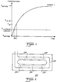
- Figure 2 is a plot of the thermal model of the printhead substrate used by the preferred embodiment of the invention.
- FIG. 3 is a block diagram of an alternate embodiment of the present invention.
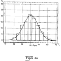
- Figure 4A is a histogram of the distribution of print-cycle temperatures that a population of printheads substrates without the present invention would experience over a typical range of user plots.
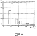
- Figure 4B is a histogram of the distribution of print-cycle temperatures that a population of printheads with the present invention would experience over the same typical range of user plots where the reference temperature equals 40°C.
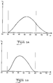
- Figure 5A is a plot of the distribution of drop volumes for a printhead substrate without the present invention.
- Figure 5B is a plot of the distribution of drop volumes for a printhead substrate made according to the preferred embodiment of the invention.
- Figure 6 shows the temperature sense resistor for the preferred embodiment of the present invention.
- Figure 7A shows print having a resolution of 300x600 dots per inch
- Figure 7B shows print having a resolution of 300x300 dots per inch.
- Figure 8 shows the effect of increasing the drop size when printing at a resolution of 300x300 dots per inch.
- Drop volume varies with printhead substrate temperature.
- the present invention uses this principle to reduce the range of drop volume variation by heating the printhead substrate to a reference temperature before printing begins and keeping it from falling below that temperature during printing.
- the preferred embodiment uses a thermal model of the printhead substrate to estimate how long to drive the printhead substrate at a particular power level to raise its temperature to the reference temperature of the printhead substrate.
- Figure 1 is a block diagram of the preferred embodiment of the present invention. It consists of a printhead substrate temperature sensor 22, also shown in Figure 6, a cartridge (i.e., the box that holds the ink and the printhead substrate) temperature (i.e., the air temperature inside the cartridge which is the ambient temperature of the printhead substrate) sensor, and a reference temperature generator.
- the outputs of these three devices are fed into a thermal model processor/comparator which calculates how long to drive the firing chamber resistors with nonprinting pulses having a known power.
- the preferred embodiment of the invention heats the printhead substrate only between swaths so it has a printhead position sensor that detects when the printhead is between swaths.
- the output of the thermal model and the output of the printhead position sensor goes to a nonprinting pulse controller that determines when the firing chamber resistors should be driven with nonprinting pulses.
- the output of the nonprinting pulse controller signals a pulse generator when to drive the firing chamber resistors with one or more packets of nonprinting pulses having the duration specified by the thermal model processor/comparator.
- Figure 2 is a plot of the thermal model of the printhead substrate.
- a and ⁇ are constants of the system.
- the inputs to the thermal model include: the reference temperature, the cartridge temperature (i.e., the temperature of the air inside the cartridge that surrounds the printhead substrate), and the printhead substrate temperature.
- the advantage of the thermal model is that the printhead substrate reaches the reference temperature with reduced iterations of measuring the printhead substrate temperature and heating the printhead substrate.
- the thermal model is part of a closed-loop system and the system may use several iterations of measuring and heating if needed.
- Figure 4A is a histogram that represents the distribution of print-cycle temperatures that a population of printheads without the present invention would see over a typical range of user plots.
- the average print-cycle temperature of these printhead substrates without the invention is T APCT and equals 40°C.
- the preferred embodiment of the invention sets the reference temperature of a printhead substrate equal to T APCT . This has the advantage of eliminating half the temperature range and, thus, half the drop volume variation due to temperature variation.
- the preferred embodiment of the invention heats the printhead substrate to the reference temperature only during the print cycle. This has the advantage of keeping the printhead substrate at lower and less destructive temperatures for longer. Additionally, the preferred embodiment of the invention heats the printhead substrate only between swaths (i.e., passes of a printhead across the page) to reduce the load on the processor and prevent a reduction in the print speed.
- An alternate embodiment of the present invention heats the printhead substrate continuously. It measures the temperature of the printhead substrate as it moves across the paper. If it is below the reference temperature the machine will send either a printing pulse if the plot requires it or a nonprinting pulse. Alternate embodiments of the invention may heat the printhead substrate at anytime without departing from the scope of the invention.
- the preferred embodiment of the invention heats the printhead substrate to the reference temperature by driving the firing chamber resistors with nonprinting pulses (i.e., pulses that heat the printhead substrate but are insufficient to cause the firing chamber resistors to eject drops).
- nonprinting pulses i.e., pulses that heat the printhead substrate but are insufficient to cause the firing chamber resistors to eject drops.
- Alternate embodiments of the invention can heat the printhead substrate in any manner (e.g., printing pulses driving any resistive element, a cartridge heater, etc.) without departing from the scope of the invention.
- the preferred embodiment uses a thermal model of the printhead substrate, having inputs of the reference temperature, the cartridge temperature, and the printhead substrate temperature, that calculates how long the firing chamber resistors of the printhead substrate should be driven with packets of nonprinting pulses delivering power at the rate of Power1 to the printhead substrate between swaths to raise the printhead substrate temperature to the reference temperature.
- FIG. 3 shows an alternate embodiment of the invention that uses an iterative approach to heating the printhead substrate to the reference temperature.
- the temperature sensor measures the printhead substrate temperature.
- An output signal 25 of the temperature sensor is processed by either a buffer-amplifier or a data converter and goes to an error detection amplifier that compares it to a reference temperature signal 36. If the printhead substrate temperature is less than the reference temperature, the closed-loop pulse generator will drive the firing chamber resistor with a series of nonprinting pulses. This process is repeated continuously during the print cycle.
- Figure 4A is a histogram of the distribution of print-cycle temperatures for a printhead substrate without the present invention.
- the average print-cycle temperature, T APCT is 40°C.
- This printhead substrate made according to the preferred embodiment of the invention operates at the reference temperature of 40° C most of the time but it does float up to higher temperatures including a maximum temperature (i.e., the highest printhead substrate temperature) when the print duty cycle is high in a warm environment.
- the preferred embodiments of the present invention sets the reference temperature equal to T APCT because it has the advantage of eliminating half the temperature range and half the range of drop volume variation due to temperature variation.
- Alternate embodiments could set the reference temperature equal to any temperature, such as above the maximum temperature, equal to the maximum temperature, somewhere between T APCT and the maximum temperature, or below T APCT without departing from the scope of the invention.
- FIG. 1 Another aspect of the invention, is a darkness control knob, shown in Figure 1, that allows the user to change the reference temperature and thereby adjust the darkness of the print or the time required for the ink to dry according to personal preference or changes in the cartridge performance. Adjustments of the darkness control knob can cause the reference temperature to exceed the maximum temperature.
- Raising the reference temperature has the advantage of reducing the range of printhead substrate temperature variation and if the reference temperature equals the maximum temperature, the printhead substrate temperature will not vary at all. But raising the reference temperature places increased stress on the printhead substrate and the ink and the likelihood of increased chemical interaction of the ink and the printhead substrate. This results in decreased reliability of the printhead. Also, a printhead substrate with a higher reference temperature will require more time for heating. Another disadvantage of raising the reference temperature is that all ink jet printer designs built to date have shown a higher chance of misfiring at higher printhead substrate temperatures.
- Figure 5A shows the drop volume range for a printhead substrate without the present invention.
- the X-axis is the volume of the drops and the Y-axis is the percentage of drops having that volume.
- the peak of the distribution curve is at 52.5 pico liters.
- the vertical lines are the lower acceptability limit (i.e., the smallest acceptable drops) and upper acceptability limit (i.e., the largest acceptable drop).
- the largest drops produced by a printhead substrate without the present invention exceed the upper acceptability limit and cause the feathering, bleeding, and block (i.e., the sleeve of a transparency film adheres to the printed area of the film and permanently changes the surface of the film) problems, as well as, the cockling and curling problems mentioned earlier.
- Drop volume is a function of the printhead substrate temperature, geometric properties of the printhead such as resistor size or nozzle diameter, and the energy contained in a printing pulse. As shown in Figure 5A, the drop volume range of printheads without the present invention is large. Typically, the drops ejected by previously-known printers at the cold, start-up printhead substrate temperatures are too small and produce substandard print. To produce larger drops at the cold, start-up temperatures, the properties of a printhead without the present invention, such as its geometry, must be adjusted so that the drops produced by a cold printhead substrate at power-on are large enough to produce satisfactory print (i.e., completely formed characters of adequate darkness).
- Figure 5B shows the drop volume range for a printhead substrate made according to the present invention.
- the peak of the distribution curve is at 47.5 pico liters and both the lower end and the upper end of the drop distribution fits inside the limits of acceptability.
- This volume distribution was obtained by using the present invention which keeps the printhead substrate temperature from falling below the reference temperature and by skewing the entire range of drop volumes down to lower drop volumes. This is accomplished by changing the geometry of the printhead such as the size of the resistors and the orifice diameter.
- an advantage of the present invention is that the largest drops can be eliminated by skewing down the entire range of drop volumes.
- FIG 6 shows the temperature sense resistor 22 that the preferred embodiment of the invention uses.
- Temperature sense resistor 22 measures the average temperature of a printhead substrate 20 since it wraps around all nozzles 24 of printhead substrate 20.
- the temperature of the ink in the drop generators is the temperature of greatest interest, but this temperature is difficult to measure directly but temperature sense resistor 22 can measure it indirectly.
- the silicon is thermally conductive and the ink is in contact with the substrate long enough that the temperature averaged around the head is very close to the temperature of the ink by the time the printhead ejects the ink.
- Printhead substrate temperature sensor 22 is inexpensive to manufacture because it does not require any processing steps or materials that are not already a part of the manufacturing procedure for thermal ink jet printheads. However, it must be calibrated using standard calibration techniques, an accurate thermistor located in the printer box, and a known temperature difference between the printhead substrate and printer box. Other possibilities for calibrating printhead substrate temperature sensor 22 include laser trimming of the resistor.
- the preferred embodiment of the invention heats the printhead substrate by using packets of nonprinting pulses.
- the power delivered by these packets equals the number of nozzles times the frequency of the nonprinting pulses (which can be much higher than that of the printing pulses since no drops are ejected from the printhead) times the energy in each nonprinting pulse.
- This power parameter is used to create the thermal model shown in Figure 2.
- the number of nozzles and the frequency of the nonprinting pulses are constant and set by other aspects of the printhead design. Alternate embodiments of the invention can vary the frequency of the nonprinting pulses and pulse some but not all of the nozzles without departing from the scope of the invention.
- the nonprinting pulses have the same voltage as the printing pulses so that the various time constants in the circuit are the same for printing pulses and nonprinting pulses.
- the pulse width and energy delivered by printing pulses are adjusted according the characteristics of each particular printhead.
- the width of nonprinting pulses is equal to or less than .48 times the width of the printing pulse so that it has little chance of ever ejecting ink from the printhead.
- the printing pulses have a width of 2.5 ⁇ sec. and the nonprinting pulses have a width of .6 ⁇ sec.
- the preferred embodiment of the invention changes the reference temperature with changes in resolution that are caused by a change in print speed.
- the resolution is 300 dots per inch along the paper feed axis and 600 dots per inch across the width of the paper in the carriage scan direction which translates into twice the number of dots across the width of the paper.
- Figure 7A shows the coverage of dots in 300 x 600 dot per inch print. If the print speed is doubled, the printhead operates the same way but the resolution becomes 300 x 300 dots per inch.
- Figure 7B shows the coverage of dots when the resolution is reduced to 300 x 300 dots per inch print. Holes open up between the dots.
- the present invention increases the reference temperature to T LDref , shown in Figure 2, so that the printhead ejects drops with a larger volume that produces larger dots that better fill in the empty space between the dots as shown in Figure 8.
Abstract
Description
- This is a continuation-in-part of a copending patent application, that will issue ,having the serial number 07/694,185 entitled METHOD AND APPARATUS FOR CONTROLLING THE TEMPERATURE OF THERMAL INK JET AND THERMAL PRINTHEADS THROUGH THE USE OF NONPRINTING PULSES filed in the name of Yeung on May 1, 1991 and owned by the assignee of this application and incorporated herein by reference. This application relates to copending application Serial No. entitled INK-COOLED THERMAL INK JET PRINTHEAD filed in the name of Seccombe et. al on November 30, 1992 and owned by the assignee of this application and is incorporated herein by reference.
- This invention relates generally to the field of thermal ink jet printers and more particularly to controlling the temperature of thermal ink jet printheads.
- Thermal ink jet printers have gained wide acceptance. These printers are described by W.J. Lloyd and H.T. Taub in "Ink Jet Devices," Chapter 13 of Output Hardcopy Devices (Ed. R.C. Durbeck and S. Sherr, San Diego: Academic Press, 1988) and U.S. Patents 4,490,728 and 4,313,684. Thermal ink jet printers produce high quality print, are compact and portable, and print quickly but quietly because only ink strikes the paper. The typical thermal ink jet printhead (i.e., the silicon substrate, structures built on the substrate, and connections to the substrate) uses liquid ink (i.e., colorants dissolved or dispersed in a solvent). It has an array of precisely formed nozzles attached to a printhead substrate that incorporates an array of firing chambers which receive liquid ink from the ink reservoir. Each chamber has a thin-film resistor, known as a thermal ink jet firing chamber resistor, located opposite the nozzle so ink can collect between it and the nozzle. When electric printing pulses heat the thermal ink jet firing chamber resistor, a small portion of the ink next to it vaporizes and ejects a drop of ink from the printhead. Properly arranged nozzles form a dot matrix pattern. Properly sequencing the operation of each nozzle causes characters or images to be printed upon the paper as the printhead moves past the paper.
- Drop volume variations result in degraded print quality and have prevented the realization of the full potential of thermal ink jet printers. Drop volumes vary with the printhead substrate temperature because the two properties that control it vary with printhead substrate temperature: the viscosity of the ink and the amount of ink vaporized by a firing chamber resistor when driven with a printing pulse. Drop volume variations commonly occur during printer startup, during changes in ambient temperature, and when the printer output varies, such as a change from normal print to "black-out" print (i.e., where the printer covers the page with dots).
- Variations in drop volume degrades print quality by causing variations in the darkness of black-and-white text, variations in the contrast of gray-scale images, and variations in the chroma, hue, and lightness of color images. The chroma, hue, and lightness of a printed color depends on the volume of all the primary color drops that create the printed color. If the printhead substrate temperature increases or decreases as the page is printed, the colors at the top of the page can differ from the colors at the bottom of the page. Reducing the range of drop volume variations will improve the quality of printed text, graphics, and images.
- Additional degradation in the print quality is cause by excessive amounts of ink in the larger drops. When at room temperature, a thermal ink jet printhead must eject drops of sufficient size to form satisfactory printed dots. However, previously known printheads that meet this performance requirement, eject drops containing excessive amounts of ink when the printhead substrate is warm. The excessive ink degraded the print by causing feathering of the ink drops, bleeding of ink drops having different colors, and cockling and curling of the paper. Reducing the range of drop volume variation would help eliminate this problem.
- For the reasons previously discussed, it would be advantageous to have an apparatus and a method for reducing the range of drop volume variation.
- The foregoing and other advantages are provided by the present invention which reduces the range of the drop volume variation by maintaining the temperature of the printhead substrate above a minimum value known as the reference temperature. The present invention includes the steps of selecting a reference temperature that can reduce the range of drop volume variation, measuring the printhead substrate temperature, comparing the printhead substrate temperature with the reference temperature, and keeping the printhead substrate temperature above the reference temperature to reduce the range of drop volume variation.
- The scope of the present invention includes heating the printhead substrate during a print cycle (i.e., the interval beginning when a printer receives a print command and ending when it executes the last command of that data stream), as well as, heating it at anytime or heating it continuously. The scope of the present invention includes heating the printhead substrate by heating the entire cartridge (i.e., the printhead substrate, the housing, connections between the printhead substrate and the ink supply, and the ink supply if it is attached to the printhead substrate) by using a cartridge heater or heating the printhead substrate more directly by driving the firing chamber resistors with nonprinting pulses (i.e., pulses that do not have sufficient energy to cause the printhead to fire). The scope of the present invention includes using a thermal model to estimate the amount of heat to deliver to the printhead substrate to raise its temperature to the reference temperature and delivering this energy between swaths to avoid slowing the printer output.
- Another aspect of the present invention varies the reference temperature according to the print resolution. When a cartridge prints at lower resolution (i.e., skipping every other dot), the space between the printed dots increases. The present invention reduces this empty space by increasing the reference temperature of the printhead substrate so that it produces larger dots. A further aspect of the present invention is a darkness knob that allows the user to vary the reference temperature and thereby control the darkness of the print and the time required for it to dry. The present invention includes a temperature sense resistor deposited around the firing chamber resistors of the printhead substrate.
- The present invention has the advantage of reducing the range of drop volume variation and increasing the quality of the print. Other advantages of the invention include a reduction in the average drop volume since a smaller drop volume range allows the designer to set the average drop volume to a lower value, a reduction in the amount of ink that the paper must absorb, and more pages per unit ink volume whether the ink supply is onboard (i.e., physically attached to printhead substrate so that it moves with it) or offboard (i.e., stationary ink supply).
- Figure 1 is a block diagram of the present invention.
- Figure 2 is a plot of the thermal model of the printhead substrate used by the preferred embodiment of the invention.
- Figure 3 is a block diagram of an alternate embodiment of the present invention.
- Figure 4A is a histogram of the distribution of print-cycle temperatures that a population of printheads substrates without the present invention would experience over a typical range of user plots.
- Figure 4B is a histogram of the distribution of print-cycle temperatures that a population of printheads with the present invention would experience over the same typical range of user plots where the reference temperature equals 40°C.
- Figure 5A is a plot of the distribution of drop volumes for a printhead substrate without the present invention.
- Figure 5B is a plot of the distribution of drop volumes for a printhead substrate made according to the preferred embodiment of the invention.
- Figure 6 shows the temperature sense resistor for the preferred embodiment of the present invention.
- Figure 7A shows print having a resolution of 300x600 dots per inch and
- Figure 7B shows print having a resolution of 300x300 dots per inch.
- Figure 8 shows the effect of increasing the drop size when printing at a resolution of 300x300 dots per inch.
- A person skilled in the art will readily appreciate the advantages and features of the disclosed invention after reading the following detailed description in conjunction with the drawings.
- Drop volume varies with printhead substrate temperature. The present invention uses this principle to reduce the range of drop volume variation by heating the printhead substrate to a reference temperature before printing begins and keeping it from falling below that temperature during printing. The preferred embodiment uses a thermal model of the printhead substrate to estimate how long to drive the printhead substrate at a particular power level to raise its temperature to the reference temperature of the printhead substrate.
- Figure 1 is a block diagram of the preferred embodiment of the present invention. It consists of a printhead
substrate temperature sensor 22, also shown in Figure 6, a cartridge (i.e., the box that holds the ink and the printhead substrate) temperature (i.e., the air temperature inside the cartridge which is the ambient temperature of the printhead substrate) sensor, and a reference temperature generator. The outputs of these three devices are fed into a thermal model processor/comparator which calculates how long to drive the firing chamber resistors with nonprinting pulses having a known power. The preferred embodiment of the invention heats the printhead substrate only between swaths so it has a printhead position sensor that detects when the printhead is between swaths. The output of the thermal model and the output of the printhead position sensor goes to a nonprinting pulse controller that determines when the firing chamber resistors should be driven with nonprinting pulses. The output of the nonprinting pulse controller signals a pulse generator when to drive the firing chamber resistors with one or more packets of nonprinting pulses having the duration specified by the thermal model processor/comparator. - Figure 2 is a plot of the thermal model of the printhead substrate. The printhead substrate has an exponential temperature rise described by:


- The advantage of the thermal model is that the printhead substrate reaches the reference temperature with reduced iterations of measuring the printhead substrate temperature and heating the printhead substrate. However, the thermal model is part of a closed-loop system and the system may use several iterations of measuring and heating if needed.
Figure 4A is a histogram that represents the distribution of print-cycle temperatures that a population of printheads without the present invention would see over a typical range of user plots. The average print-cycle temperature of these printhead substrates without the invention is TAPCT and equals 40°C. The preferred embodiment of the invention sets the reference temperature of a printhead substrate equal to TAPCT. This has the advantage of eliminating half the temperature range and, thus, half the drop volume variation due to temperature variation. - The preferred embodiment of the invention heats the printhead substrate to the reference temperature only during the print cycle. This has the advantage of keeping the printhead substrate at lower and less destructive temperatures for longer. Additionally, the preferred embodiment of the invention heats the printhead substrate only between swaths (i.e., passes of a printhead across the page) to reduce the load on the processor and prevent a reduction in the print speed. An alternate embodiment of the present invention heats the printhead substrate continuously. It measures the temperature of the printhead substrate as it moves across the paper. If it is below the reference temperature the machine will send either a printing pulse if the plot requires it or a nonprinting pulse. Alternate embodiments of the invention may heat the printhead substrate at anytime without departing from the scope of the invention.
- The preferred embodiment of the invention heats the printhead substrate to the reference temperature by driving the firing chamber resistors with nonprinting pulses (i.e., pulses that heat the printhead substrate but are insufficient to cause the firing chamber resistors to eject drops). Alternate embodiments of the invention can heat the printhead substrate in any manner (e.g., printing pulses driving any resistive element, a cartridge heater, etc.) without departing from the scope of the invention.
- In summary, the preferred embodiment uses a thermal model of the printhead substrate, having inputs of the reference temperature, the cartridge temperature, and the printhead substrate temperature, that calculates how long the firing chamber resistors of the printhead substrate should be driven with packets of nonprinting pulses delivering power at the rate of Power₁ to the printhead substrate between swaths to raise the printhead substrate temperature to the reference temperature.
- Figure 3 shows an alternate embodiment of the invention that uses an iterative approach to heating the printhead substrate to the reference temperature. The temperature sensor measures the printhead substrate temperature. An
output signal 25 of the temperature sensor is processed by either a buffer-amplifier or a data converter and goes to an error detection amplifier that compares it to areference temperature signal 36. If the printhead substrate temperature is less than the reference temperature, the closed-loop pulse generator will drive the firing chamber resistor with a series of nonprinting pulses. This process is repeated continuously during the print cycle. This and other aspects of the present invention are described in U.S. Patent Application 07/694,184 hereby incorporated by reference. - As stated earlier, Figure 4A is a histogram of the distribution of print-cycle temperatures for a printhead substrate without the present invention. The average print-cycle temperature, TAPCT, is 40°C. When the population of printhead substrates with the histogram of print-cycle temperature distributions shown in Figure 4A adopts the present invention with the reference temperature set at TAPCT, 40° C, these printhead substrates obtain the histogram of print-cycle temperature distributions shown in Figure 4B. It is a skewed-normal distribution with the lower temperatures of Figure 4A avoided by use of the present invention. This printhead substrate made according to the preferred embodiment of the invention operates at the reference temperature of 40° C most of the time but it does float up to higher temperatures including a maximum temperature (i.e., the highest printhead substrate temperature) when the print duty cycle is high in a warm environment.
- As stated earlier the preferred embodiments of the present invention, sets the reference temperature equal to TAPCT because it has the advantage of eliminating half the temperature range and half the range of drop volume variation due to temperature variation. Alternate embodiments could set the reference temperature equal to any temperature, such as above the maximum temperature, equal to the maximum temperature, somewhere between TAPCT and the maximum temperature, or below TAPCT without departing from the scope of the invention.
- Another aspect of the invention, is a darkness control knob, shown in Figure 1, that allows the user to change the reference temperature and thereby adjust the darkness of the print or the time required for the ink to dry according to personal preference or changes in the cartridge performance. Adjustments of the darkness control knob can cause the reference temperature to exceed the maximum temperature.
- Raising the reference temperature has the advantage of reducing the range of printhead substrate temperature variation and if the reference temperature equals the maximum temperature, the printhead substrate temperature will not vary at all. But raising the reference temperature places increased stress on the printhead substrate and the ink and the likelihood of increased chemical interaction of the ink and the printhead substrate. This results in decreased reliability of the printhead. Also, a printhead substrate with a higher reference temperature will require more time for heating. Another disadvantage of raising the reference temperature is that all ink jet printer designs built to date have shown a higher chance of misfiring at higher printhead substrate temperatures.
- Figure 5A shows the drop volume range for a printhead substrate without the present invention. The X-axis is the volume of the drops and the Y-axis is the percentage of drops having that volume. The peak of the distribution curve is at 52.5 pico liters. The vertical lines are the lower acceptability limit (i.e., the smallest acceptable drops) and upper acceptability limit (i.e., the largest acceptable drop). The largest drops produced by a printhead substrate without the present invention exceed the upper acceptability limit and cause the feathering, bleeding, and block (i.e., the sleeve of a transparency film adheres to the printed area of the film and permanently changes the surface of the film) problems, as well as, the cockling and curling problems mentioned earlier.
- Drop volume is a function of the printhead substrate temperature, geometric properties of the printhead such as resistor size or nozzle diameter, and the energy contained in a printing pulse. As shown in Figure 5A, the drop volume range of printheads without the present invention is large. Typically, the drops ejected by previously-known printers at the cold, start-up printhead substrate temperatures are too small and produce substandard print. To produce larger drops at the cold, start-up temperatures, the properties of a printhead without the present invention, such as its geometry, must be adjusted so that the drops produced by a cold printhead substrate at power-on are large enough to produce satisfactory print (i.e., completely formed characters of adequate darkness). When these printhead substrates heat-up, they produce drops of excessively large volumes (as shown in Figure 5A) that change the saturation level of the graphics, make the text bloomy, and create print that does not dry quickly and results in ink that bleeds, blocks , or smears and paper that cockles or curls. For these reasons, it is desirable to reduce the volume of the larger drops.
- Figure 5B shows the drop volume range for a printhead substrate made according to the present invention. The peak of the distribution curve is at 47.5 pico liters and both the lower end and the upper end of the drop distribution fits inside the limits of acceptability. This volume distribution was obtained by using the present invention which keeps the printhead substrate temperature from falling below the reference temperature and by skewing the entire range of drop volumes down to lower drop volumes. This is accomplished by changing the geometry of the printhead such as the size of the resistors and the orifice diameter. Thus, an advantage of the present invention is that the largest drops can be eliminated by skewing down the entire range of drop volumes.
- Figure 6 shows the
temperature sense resistor 22 that the preferred embodiment of the invention uses.Temperature sense resistor 22 measures the average temperature of aprinthead substrate 20 since it wraps around allnozzles 24 ofprinthead substrate 20. The temperature of the ink in the drop generators is the temperature of greatest interest, but this temperature is difficult to measure directly buttemperature sense resistor 22 can measure it indirectly. The silicon is thermally conductive and the ink is in contact with the substrate long enough that the temperature averaged around the head is very close to the temperature of the ink by the time the printhead ejects the ink. - Printhead
substrate temperature sensor 22 is inexpensive to manufacture because it does not require any processing steps or materials that are not already a part of the manufacturing procedure for thermal ink jet printheads. However, it must be calibrated using standard calibration techniques, an accurate thermistor located in the printer box, and a known temperature difference between the printhead substrate and printer box. Other possibilities for calibrating printheadsubstrate temperature sensor 22 include laser trimming of the resistor. - The preferred embodiment of the invention heats the printhead substrate by using packets of nonprinting pulses. The power delivered by these packets equals the number of nozzles times the frequency of the nonprinting pulses (which can be much higher than that of the printing pulses since no drops are ejected from the printhead) times the energy in each nonprinting pulse. This power parameter is used to create the thermal model shown in Figure 2. The number of nozzles and the frequency of the nonprinting pulses are constant and set by other aspects of the printhead design. Alternate embodiments of the invention can vary the frequency of the nonprinting pulses and pulse some but not all of the nozzles without departing from the scope of the invention.
- In the preferred embodiment of the invention, the nonprinting pulses have the same voltage as the printing pulses so that the various time constants in the circuit are the same for printing pulses and nonprinting pulses. The pulse width and energy delivered by printing pulses are adjusted according the characteristics of each particular printhead. The width of nonprinting pulses is equal to or less than .48 times the width of the printing pulse so that it has little chance of ever ejecting ink from the printhead. In the preferred embodiment of the invention, the printing pulses have a width of 2.5 µsec. and the nonprinting pulses have a width of .6µsec.
- The preferred embodiment of the invention changes the reference temperature with changes in resolution that are caused by a change in print speed. At the standard print speed, the resolution is 300 dots per inch along the paper feed axis and 600 dots per inch across the width of the paper in the carriage scan direction which translates into twice the number of dots across the width of the paper. Figure 7A shows the coverage of dots in 300 x 600 dot per inch print. If the print speed is doubled, the printhead operates the same way but the resolution becomes 300 x 300 dots per inch. Figure 7B shows the coverage of dots when the resolution is reduced to 300 x 300 dots per inch print. Holes open up between the dots. At the lower resolution modes, the present invention increases the reference temperature to TLDref, shown in Figure 2, so that the printhead ejects drops with a larger volume that produces larger dots that better fill in the empty space between the dots as shown in Figure 8.
- The increase in temperature between Tref and TLDref depends on how drop volume increases with temperature, the pl/°C rating, and the dot size versus drop volume. If the printhead experiences .5pl change per degree C, then switching from Tref = 40°C to TLDref = 55° C produce a drop volume change of 7.5pl. Even though the reference temperature is increased, the pulse width and voltage remain the same.
- All publications and patent applications cited in the specification are herein incorporated by reference as if each publication or patent application were specifically and individually indicated to be incorporated by reference.
- The foregoing description of the preferred embodiment of the present invention has been presented for the purposes of illustration and description. It is not intended to be exhaustive nor to limit the invention to the precise form disclosed. Obviously many modifications and variations are possible in light of the above teachings. The embodiments were chosen in order to best explain the best mode of the invention. Thus, it is intended that the scope of the invention to be defined by the claims appended hereto.
Claims (10)
- A method for reducing a range of drop volume variation of a thermal ink jet printhead, comprising the steps of:a. selecting a reference temperature that can reduce the range of drop volume variation;b. measuring a temperature of the printhead substrate (20);c. comparing the printhead substrate (20) temperature with the reference temperature; andd. heating the printhead substrate (20) to the reference temperature to reduce the range of drop volume variation.
- The method, as in claim 1, further comprising the step of heating the printhead substrate (20) by driving a firing chamber resistor on the printhead substrate with nonprinting pulses.
- The method, as in claim 1 or 2, further comprising the step of heating the printhead substrate (20) to the reference temperature during the print cycle.
- The method, as in claim 3, further comprising the step of setting the reference temperature equal to a maximum temperature of the printhead substrate (20).
- The method, as in claim 3, further comprising the step of setting the reference temperature below an average print-cycle temperature.
- The method, as in claim 3, further comprising the step of setting the reference temperature between an average print-cycle temperature and a maximum temperature of the printhead substrate (20).
- The method, as in claim 3, further comprising the step of setting the reference temperature equal to approximately an average print-cycle temperature of the printhead substrate (20).
- The method, as in claim 1 or 2 or 7, further comprising the step of increasing the reference temperature when a print resolution of the printhead substrate (20) decreases.
- The method, as in claim 1 or 2 or 7, further comprising the step of using a thermal model of the printhead substrate (20) to estimate how much energy the nonprinting pulses should deliver to the firing chamber resistors.
- The method, as in claim 1 or 2 or 7, further comprising the step of varying the reference temperature in response to an user input.
Applications Claiming Priority (2)
| Application Number | Priority Date | Filing Date | Title |
|---|---|---|---|
| US98300992A | 1992-11-30 | 1992-11-30 | |
| US983009 | 1992-11-30 |
Publications (3)
| Publication Number | Publication Date |
|---|---|
| EP0600648A2 true EP0600648A2 (en) | 1994-06-08 |
| EP0600648A3 EP0600648A3 (en) | 1995-01-04 |
| EP0600648B1 EP0600648B1 (en) | 2001-10-24 |
Family
ID=25529738
Family Applications (1)
| Application Number | Title | Priority Date | Filing Date |
|---|---|---|---|
| EP19930309242 Expired - Lifetime EP0600648B1 (en) | 1992-11-30 | 1993-11-19 | Method and apparatus for the control of thermal ink jet printers |
Country Status (4)
| Country | Link |
|---|---|
| EP (1) | EP0600648B1 (en) |
| JP (1) | JP3408302B2 (en) |
| DE (1) | DE69330991T2 (en) |
| SG (1) | SG47457A1 (en) |
Cited By (6)
| Publication number | Priority date | Publication date | Assignee | Title |
|---|---|---|---|---|
| EP0650836A2 (en) * | 1993-10-27 | 1995-05-03 | Hewlett-Packard Company | Temperature control of thermal ink-jet print heads by using synchronous non-nucleating pulses |
| EP0654351A2 (en) * | 1993-11-22 | 1995-05-24 | Hewlett-Packard Company | Inkdrop-volume test using heat-flow effects, for thermal-inkjet printers |
| EP0694392A3 (en) * | 1994-07-29 | 1996-07-31 | Canon Kk | Ink jet printing method and apparatus therefor |
| US5736995A (en) * | 1991-05-01 | 1998-04-07 | Hewlett-Packard Company | Temperature control of thermal inkjet printheads by using synchronous non-nucleating pulses |
| US7782350B2 (en) | 2006-12-13 | 2010-08-24 | Canon Kabushiki Kaisha | Printing apparatus, printing system, printhead temperature retaining control method |
| CN115056578A (en) * | 2022-05-20 | 2022-09-16 | 深圳市美松智能设备有限公司 | Thermal transfer printer and printing method |
Families Citing this family (1)
| Publication number | Priority date | Publication date | Assignee | Title |
|---|---|---|---|---|
| JP5072573B2 (en) | 2007-01-09 | 2012-11-14 | キヤノン株式会社 | Recording apparatus and recording head control method |
Citations (6)
| Publication number | Priority date | Publication date | Assignee | Title |
|---|---|---|---|---|
| GB2169855A (en) * | 1984-12-21 | 1986-07-23 | Canon Kk | Liquid-jet recorder |
| GB2169856A (en) * | 1984-12-28 | 1986-07-23 | Canon Kk | Ink-jet recording |
| WO1990010541A1 (en) * | 1989-03-14 | 1990-09-20 | Siemens Aktiengesellschaft | Process for varying the droplet size in ink printers |
| EP0416557A1 (en) * | 1989-09-05 | 1991-03-13 | Canon Kabushiki Kaisha | Liquid jet recording head |
| US5036337A (en) * | 1990-06-22 | 1991-07-30 | Xerox Corporation | Thermal ink jet printhead with droplet volume control |
| EP0511602A1 (en) * | 1991-05-01 | 1992-11-04 | Hewlett-Packard Company | Method and apparatus for controlling the temperature of thermal ink jet and thermal printheads through the use of nonprinting pulses |
-
1993
- 1993-11-19 EP EP19930309242 patent/EP0600648B1/en not_active Expired - Lifetime
- 1993-11-19 SG SG1996001818A patent/SG47457A1/en unknown
- 1993-11-19 DE DE1993630991 patent/DE69330991T2/en not_active Expired - Lifetime
- 1993-11-30 JP JP32600793A patent/JP3408302B2/en not_active Expired - Lifetime
Patent Citations (6)
| Publication number | Priority date | Publication date | Assignee | Title |
|---|---|---|---|---|
| GB2169855A (en) * | 1984-12-21 | 1986-07-23 | Canon Kk | Liquid-jet recorder |
| GB2169856A (en) * | 1984-12-28 | 1986-07-23 | Canon Kk | Ink-jet recording |
| WO1990010541A1 (en) * | 1989-03-14 | 1990-09-20 | Siemens Aktiengesellschaft | Process for varying the droplet size in ink printers |
| EP0416557A1 (en) * | 1989-09-05 | 1991-03-13 | Canon Kabushiki Kaisha | Liquid jet recording head |
| US5036337A (en) * | 1990-06-22 | 1991-07-30 | Xerox Corporation | Thermal ink jet printhead with droplet volume control |
| EP0511602A1 (en) * | 1991-05-01 | 1992-11-04 | Hewlett-Packard Company | Method and apparatus for controlling the temperature of thermal ink jet and thermal printheads through the use of nonprinting pulses |
Cited By (10)
| Publication number | Priority date | Publication date | Assignee | Title |
|---|---|---|---|---|
| US5736995A (en) * | 1991-05-01 | 1998-04-07 | Hewlett-Packard Company | Temperature control of thermal inkjet printheads by using synchronous non-nucleating pulses |
| EP0650836A2 (en) * | 1993-10-27 | 1995-05-03 | Hewlett-Packard Company | Temperature control of thermal ink-jet print heads by using synchronous non-nucleating pulses |
| EP0650836A3 (en) * | 1993-10-27 | 1997-03-12 | Hewlett Packard Co | Temperature control of thermal ink-jet print heads by using synchronous non-nucleating pulses. |
| EP0654351A2 (en) * | 1993-11-22 | 1995-05-24 | Hewlett-Packard Company | Inkdrop-volume test using heat-flow effects, for thermal-inkjet printers |
| EP0654351A3 (en) * | 1993-11-22 | 1997-06-11 | Hewlett Packard Co | Inkdrop-volume test using heat-flow effects, for thermal-inkjet printers. |
| EP0694392A3 (en) * | 1994-07-29 | 1996-07-31 | Canon Kk | Ink jet printing method and apparatus therefor |
| US5838340A (en) * | 1994-07-29 | 1998-11-17 | Canon Kabushiki Kaisha | Ink-jet printing method and apparatus therefor |
| US7782350B2 (en) | 2006-12-13 | 2010-08-24 | Canon Kabushiki Kaisha | Printing apparatus, printing system, printhead temperature retaining control method |
| CN101200134B (en) * | 2006-12-13 | 2012-11-21 | 佳能株式会社 | Printing apparatus, printing system, printhead temperature retaining control method |
| CN115056578A (en) * | 2022-05-20 | 2022-09-16 | 深圳市美松智能设备有限公司 | Thermal transfer printer and printing method |
Also Published As
| Publication number | Publication date |
|---|---|
| SG47457A1 (en) | 1998-04-17 |
| JPH06278291A (en) | 1994-10-04 |
| JP3408302B2 (en) | 2003-05-19 |
| DE69330991D1 (en) | 2001-11-29 |
| EP0600648B1 (en) | 2001-10-24 |
| EP0600648A3 (en) | 1995-01-04 |
| DE69330991T2 (en) | 2002-04-04 |
Similar Documents
| Publication | Publication Date | Title |
|---|---|---|
| US5736995A (en) | Temperature control of thermal inkjet printheads by using synchronous non-nucleating pulses | |
| US5673069A (en) | Method and apparatus for reducing the size of drops ejected from a thermal ink jet printhead | |
| EP0511602B1 (en) | Method and apparatus for controlling the temperature of thermal ink jet and thermal printheads through the use of nonprinting pulses | |
| US5726690A (en) | Control of ink drop volume in thermal inkjet printheads by varying the pulse width of the firing pulses | |
| EP1093918B1 (en) | System and method for controlling the temperature of an inkjet printhead using dynamic pulse with adjustment | |
| US5497174A (en) | Voltage drop correction for ink jet printer | |
| EP0558221A2 (en) | Electronic spot size control in a thermal ink jet printer | |
| EP2701916B1 (en) | Compensating for capacitance changes in piezoelectric printhead elements | |
| EP3426493B1 (en) | Printhead calibration | |
| JPH07186391A (en) | Ink jet printer | |
| JP2003311971A (en) | Apparatus and method for maintaining constant liquid drop volume in continuous stream ink jet printer | |
| US5642142A (en) | Variable halftone operation inkjet printheads | |
| US20030142159A1 (en) | Estimating local ejection chamber temperature to improve printhead performance | |
| US6312078B1 (en) | Imaging apparatus and method of providing images of uniform print density | |
| EP0600648B1 (en) | Method and apparatus for the control of thermal ink jet printers | |
| US20020149639A1 (en) | System and method for optimizing temperature operating ranges for a thermal inkjet printhead | |
| JPH05220963A (en) | Delivery control method in ink jet recording head | |
| EP1022139B1 (en) | Ink jet printers | |
| US20050007403A1 (en) | Printing apparatus and method for maintaining temperature of a printhead | |
| US6481823B1 (en) | Method for using highly energetic droplet firing events to improve droplet ejection reliability | |
| JPH06278283A (en) | Recording method and apparatus | |
| EP0649746A1 (en) | Variable halftone operation inkjet printheads | |
| EP0650836B1 (en) | Temperature control of thermal ink-jet print heads by using synchronous non-nucleating pulses | |
| JP3278682B2 (en) | Ink jet recording device | |
| US6648442B2 (en) | Compensation for temperature dependent drop quantity variation |
Legal Events
| Date | Code | Title | Description |
|---|---|---|---|
| PUAI | Public reference made under article 153(3) epc to a published international application that has entered the european phase |
Free format text: ORIGINAL CODE: 0009012 |
|
| AK | Designated contracting states |
Kind code of ref document: A2 Designated state(s): DE FR GB IT |
|
| PUAL | Search report despatched |
Free format text: ORIGINAL CODE: 0009013 |
|
| AK | Designated contracting states |
Kind code of ref document: A3 Designated state(s): DE FR GB IT |
|
| 17P | Request for examination filed |
Effective date: 19950223 |
|
| 17Q | First examination report despatched |
Effective date: 19960131 |
|
| GRAG | Despatch of communication of intention to grant |
Free format text: ORIGINAL CODE: EPIDOS AGRA |
|
| RAP1 | Party data changed (applicant data changed or rights of an application transferred) |
Owner name: HEWLETT-PACKARD COMPANY, A DELAWARE CORPORATION |
|
| GRAG | Despatch of communication of intention to grant |
Free format text: ORIGINAL CODE: EPIDOS AGRA |
|
| GRAH | Despatch of communication of intention to grant a patent |
Free format text: ORIGINAL CODE: EPIDOS IGRA |
|
| GRAH | Despatch of communication of intention to grant a patent |
Free format text: ORIGINAL CODE: EPIDOS IGRA |
|
| GRAA | (expected) grant |
Free format text: ORIGINAL CODE: 0009210 |
|
| AK | Designated contracting states |
Kind code of ref document: B1 Designated state(s): DE FR GB IT |
|
| PG25 | Lapsed in a contracting state [announced via postgrant information from national office to epo] |
Ref country code: IT Free format text: LAPSE BECAUSE OF FAILURE TO SUBMIT A TRANSLATION OF THE DESCRIPTION OR TO PAY THE FEE WITHIN THE PRE;WARNING: LAPSES OF ITALIAN PATENTS WITH EFFECTIVE DATE BEFORE 2007 MAY HAVE OCCURRED AT ANY TIME BEFORE 2007. THE CORRECT EFFECTIVE DATE MAY BE DIFFERENT FROM THE ONE RECORDED.SCRIBED TIME-LIMIT Effective date: 20011024 |
|
| REF | Corresponds to: |
Ref document number: 69330991 Country of ref document: DE Date of ref document: 20011129 |
|
| REG | Reference to a national code |
Ref country code: GB Ref legal event code: IF02 |
|
| ET | Fr: translation filed | ||
| PLBE | No opposition filed within time limit |
Free format text: ORIGINAL CODE: 0009261 |
|
| STAA | Information on the status of an ep patent application or granted ep patent |
Free format text: STATUS: NO OPPOSITION FILED WITHIN TIME LIMIT |
|
| 26N | No opposition filed | ||
| REG | Reference to a national code |
Ref country code: GB Ref legal event code: 732E Free format text: REGISTERED BETWEEN 20120329 AND 20120404 |
|
| PGFP | Annual fee paid to national office [announced via postgrant information from national office to epo] |
Ref country code: DE Payment date: 20121128 Year of fee payment: 20 Ref country code: FR Payment date: 20121206 Year of fee payment: 20 |
|
| PGFP | Annual fee paid to national office [announced via postgrant information from national office to epo] |
Ref country code: GB Payment date: 20121126 Year of fee payment: 20 |
|
| REG | Reference to a national code |
Ref country code: DE Ref legal event code: R071 Ref document number: 69330991 Country of ref document: DE |
|
| REG | Reference to a national code |
Ref country code: GB Ref legal event code: PE20 Expiry date: 20131118 |
|
| PG25 | Lapsed in a contracting state [announced via postgrant information from national office to epo] |
Ref country code: GB Free format text: LAPSE BECAUSE OF EXPIRATION OF PROTECTION Effective date: 20131118 Ref country code: DE Free format text: LAPSE BECAUSE OF EXPIRATION OF PROTECTION Effective date: 20131120 |