EP0600705A1 - Surface acoustic wave filter and mobile communication system using same - Google Patents
Surface acoustic wave filter and mobile communication system using same Download PDFInfo
- Publication number
- EP0600705A1 EP0600705A1 EP93309533A EP93309533A EP0600705A1 EP 0600705 A1 EP0600705 A1 EP 0600705A1 EP 93309533 A EP93309533 A EP 93309533A EP 93309533 A EP93309533 A EP 93309533A EP 0600705 A1 EP0600705 A1 EP 0600705A1
- Authority
- EP
- European Patent Office
- Prior art keywords
- acoustic wave
- surface acoustic
- wave filter
- filter
- port surface
- Prior art date
- Legal status (The legal status is an assumption and is not a legal conclusion. Google has not performed a legal analysis and makes no representation as to the accuracy of the status listed.)
- Granted
Links
- 238000010897 surface acoustic wave method Methods 0.000 title claims abstract description 624
- 238000010295 mobile communication Methods 0.000 title claims description 11
- 239000002131 composite material Substances 0.000 claims abstract description 78
- 239000000758 substrate Substances 0.000 claims description 37
- 238000003780 insertion Methods 0.000 description 79
- 230000037431 insertion Effects 0.000 description 79
- 230000001965 increasing effect Effects 0.000 description 34
- 238000010586 diagram Methods 0.000 description 20
- 230000001939 inductive effect Effects 0.000 description 9
- 230000002457 bidirectional effect Effects 0.000 description 8
- 238000013461 design Methods 0.000 description 4
- 230000001771 impaired effect Effects 0.000 description 4
- 238000006243 chemical reaction Methods 0.000 description 3
- 239000003990 capacitor Substances 0.000 description 2
- 230000005284 excitation Effects 0.000 description 2
- 238000013459 approach Methods 0.000 description 1
- 230000005540 biological transmission Effects 0.000 description 1
- 230000015572 biosynthetic process Effects 0.000 description 1
- 230000008878 coupling Effects 0.000 description 1
- 238000010168 coupling process Methods 0.000 description 1
- 238000005859 coupling reaction Methods 0.000 description 1
- 230000007423 decrease Effects 0.000 description 1
- 230000005577 local transmission Effects 0.000 description 1
- 238000012986 modification Methods 0.000 description 1
- 230000004048 modification Effects 0.000 description 1
- 230000005855 radiation Effects 0.000 description 1
- 230000005236 sound signal Effects 0.000 description 1
- 230000001629 suppression Effects 0.000 description 1
Images


Classifications
-
- H—ELECTRICITY
- H03—ELECTRONIC CIRCUITRY
- H03H—IMPEDANCE NETWORKS, e.g. RESONANT CIRCUITS; RESONATORS
- H03H9/00—Networks comprising electromechanical or electro-acoustic devices; Electromechanical resonators
- H03H9/46—Filters
- H03H9/64—Filters using surface acoustic waves
- H03H9/6423—Means for obtaining a particular transfer characteristic
- H03H9/6433—Coupled resonator filters
- H03H9/6483—Ladder SAW filters
-
- H—ELECTRICITY
- H03—ELECTRONIC CIRCUITRY
- H03H—IMPEDANCE NETWORKS, e.g. RESONANT CIRCUITS; RESONATORS
- H03H9/00—Networks comprising electromechanical or electro-acoustic devices; Electromechanical resonators
- H03H9/02—Details
- H03H9/125—Driving means, e.g. electrodes, coils
- H03H9/145—Driving means, e.g. electrodes, coils for networks using surface acoustic waves
- H03H9/14544—Transducers of particular shape or position
- H03H9/1455—Transducers of particular shape or position constituted of N parallel or series transducers
-
- H—ELECTRICITY
- H03—ELECTRONIC CIRCUITRY
- H03H—IMPEDANCE NETWORKS, e.g. RESONANT CIRCUITS; RESONATORS
- H03H9/00—Networks comprising electromechanical or electro-acoustic devices; Electromechanical resonators
- H03H9/46—Filters
- H03H9/64—Filters using surface acoustic waves
- H03H9/6423—Means for obtaining a particular transfer characteristic
- H03H9/6433—Coupled resonator filters
- H03H9/6436—Coupled resonator filters having one acoustic track only
-
- H—ELECTRICITY
- H03—ELECTRONIC CIRCUITRY
- H03H—IMPEDANCE NETWORKS, e.g. RESONANT CIRCUITS; RESONATORS
- H03H9/00—Networks comprising electromechanical or electro-acoustic devices; Electromechanical resonators
- H03H9/46—Filters
- H03H9/64—Filters using surface acoustic waves
- H03H9/6423—Means for obtaining a particular transfer characteristic
- H03H9/6433—Coupled resonator filters
- H03H9/644—Coupled resonator filters having two acoustic tracks
- H03H9/6456—Coupled resonator filters having two acoustic tracks being electrically coupled
- H03H9/6469—Coupled resonator filters having two acoustic tracks being electrically coupled via two connecting electrodes
-
- H—ELECTRICITY
- H03—ELECTRONIC CIRCUITRY
- H03H—IMPEDANCE NETWORKS, e.g. RESONANT CIRCUITS; RESONATORS
- H03H9/00—Networks comprising electromechanical or electro-acoustic devices; Electromechanical resonators
- H03H9/02—Details
- H03H9/125—Driving means, e.g. electrodes, coils
- H03H9/145—Driving means, e.g. electrodes, coils for networks using surface acoustic waves
- H03H9/14517—Means for weighting
- H03H9/14526—Finger withdrawal
Landscapes
- Physics & Mathematics (AREA)
- Acoustics & Sound (AREA)
- Surface Acoustic Wave Elements And Circuit Networks Thereof (AREA)
Abstract
Description
- The present invention relates to a surface acoustic wave filter, and a composite surface acoustic wave filter composed of a surface acoustic wave filter and a one-port surface acoustic wave resonator, and more particularly to a surface acoustic wave filter having a low insertion loss in the RF band, which is suitable for use in a mobile communication system or the like, a composite surface acoustic wave filter, and a mobile communication system which employs these filters.
- FIG. 19 of the accompanying drawings shows a conventional interdigitated interdigital surface
acoustic wave filter 11 with normal transducers on a substrate 111. If the number of transducers is indicated by (2m + 1), then the bidirectional loss BL (dB) of the interdigitated interdigital surfaceacoustic wave filter 11 is represented by:
- The bidirectional losses BL for the different numbers of transducers are given in the following table:
2m + 1 BL (dB) 5 1.80 7 1.25 9 0.97 11 0.70 13 0.67 - Since the interdigitated interdigital surface
acoustic wave filter 11 shown in FIG. 19 has 5 transducers, its bidirectional loss BL is 1.80 dB. It can be seen from the table that increasing the number of transducers is effective to reduce the bidirectional loss BL. - The input admittance Y of the transducers is expressed by the following equation (2):

where


and CS represents the capacitance per transducer port, f the frequency, fO the center frequency, N the number of electrode finger pairs, W the aperture length, εO the dielectric constant of vacuum, εr the dielectric constant of the substrate, and k the electromechanical coupling coefficient. - The above equations indicate that as the number of electrode finger pairs increases, the radiation conductance Ga increases and the input impedance decreases. Since the transducers are electrically connected parallel to each other in the interdigital configuration, the input impedance is lower as the number of transducers (2m + 1) is greater.
- To reduce the passband of a surface acoustic wave filter, the number of electrode finger pairs of each transducer is increased. Therefore, the input impedance of each transducer is reduced, making it impossible to increase the number of interdigital transducers due to the impedance limitation. As a consequence, the bidirectional loss of the surface acoustic wave filter is increased, resulting in a greater insertion loss.
- For example, it is assumed that the number of electrode finger pairs per input transducer is 22, the number of electrode finger pairs per output transducer is 30, and the aperture length is 20λ (λ is the wavelength of the input signal) in the interdigitated interdigital surface
acoustic wave filter 11 with the 5 transducers (the electrode finger pairs are shown as fewer than actual in FIG. 19). The impedances of such interdigitated interdigital surfaceacoustic wave filter 11 are calculated, and shown in FIGS. 20A and 20B with respect to normalized frequencies ranging from 0.9 to 1.1. FIG. 20A shows the calculated impedances on the input transducers, and FIG. 20B shows the calculated impedances on the output transducers. For a 50 Ω-impedance arrangement, the input and output sides can be matched by using a matching circuit shown in FIG. 21A. - As described above, the bidirectional loss of an interdigitated interdigital surface acoustic wave filter with 5 transducers is 1.80 dB (see the above table). Lowering the bidirectional loss requires that the number of transducers be increased. If the number of transducers is increased, however, the impedances are reduced. For example, a surface
acoustic wave filter 12 with 13 transducers on asubstrate 121 as shown in FIG. 22 has impedances as shown in FIGS. 23A and 23B with respect to normalized frequencies ranging from 0.9 to 1.1. FIG. 23A shows the calculated impedances on the input transducers, and FIG. 23B shows the calculated impedances on the output transducers. The impedances which are lowered can be matched in a passband by using a 4-element matching circuit shown in FIG. 21B which includescapacitors 32I, 320 added to the matching circuit shown in FIG. 21A. As a result, the surfaceacoustic wave filter 12 has insertion loss vs. frequency characteristics as shown in FIG. 24. While the bidirectional loss of the surfaceacoustic wave filter 12 is about 1.0 dB lower than that of the surface acoustic wave filter with 5 transducers, the number of matching elements required is increased. - As shown in FIG. 24, the insertion loss vs. frequency characteristics of the surface
acoustic wave filter 12 with normal transducers to which the matching circuit shown in FIG. 21B is connected suffer large side lobes outside of the passband. For suppressing such large side lobes, it is necessary to weight the transducers. However, although the side lobes of a surface acoustic wave filter with weighted transducers is suppressed, the surface acoustic wave filter has a widened trap frequency band as indicated by the arrows in FIG. 24. - FIG. 25 shows an interdigitated interdigital surface
acoustic wave filter 10 which employs different withdrawal-weighted transducers for suppressing out-band side lobes. As shown in FIG. 25, the interdigitated interdigital surfaceacoustic wave filter 10 has 13 transducers on asubstrate 131. FIG. 26 shows insertion loss vs. frequency characteristics of the surfaceacoustic wave filter 10 with the matching circuit shown in FIG. 21B being connected thereto. While the side lobes in the insertion loss vs. frequency characteristics shown in FIG. 26 are smaller than those in insertion loss vs. frequency characteristics shown in FIG. 24, the attenuation in the vicinity of the passband is lowered due to a widened trap frequency band. - As shown in FIG. 27, there has also been known an
transducer 14 with an increased number of electrode finger pairs on a substrate 141 for use with surface acoustic waves. The impedance of thetransducer 14 with many electrode finger pairs exhibits resonant characteristics as shown in FIG. 28. It is known that when thetransducer 14 or resonator is inserted in series with a circuit, it provides a stop band at an antiresonant frequency. Since thetransducer 14 functions as a capacitive element in the passband, the impedance is low and the loss is small if the capacitance of the capacitive element is large. However, since there is usually a limitation on the capacitance, the impedance is prevented from being reduced as desired, causing an undue loss. - As shown in FIG. 29, a conventional two-port surface acoustic
wave resonator filter 20 comprises aninput transducer 21, twooutput transducers input transducer 21 and electrically connected parallel to each other, and tworeflectors output transducers wave resonator filter 20. The insertion loss vs. frequency characteristics shown in FIG. 30 were calculated when the substrate was made of 64y-xLiNbO₃, the number of input electrode finger pairs was 18.5, the number of output electrode finger pairs was 12.5, and the aperture length was about 60λ where λ is the wavelength of the input signal. - The two-port surface acoustic
wave resonator filter 20 suffers a low insertion loss, and has good attenuation characteristics in a frequency band remote from the passband. However, the two-port surface acousticwave resonator filter 20 essentially gives rise to a side lobe in a frequency range near and higher than the passband. - To avoid the above difficulty, another conventional two-port surface acoustic
wave resonator filter 40 shown in FIG. 31 is composed of the two-port surface acousticwave resonator filter 20 having theinput transducer 21, theoutput transducers reflectors wave resonator filter 30 having aninput transducer 31, theoutput transducers reflectors wave resonator filter 20, the two-port surface acousticwave resonator filters wave resonator filter 40 achieves a large out-band attenuation level. - As shown in FIG. 32, still another conventional two-port surface acoustic
wave resonator filter 50 comprises aninput transducer 51, anoutput transducer 52, areflector 53a disposed outside of theinput transducer 51, and areflector 53b disposed outside of theoutput transducer 52. These transducers are formed on one substrate. The two-port surface acousticwave resonator filter 50 has calculated insertion loss vs. frequency characteristics as shown in FIG. 33. As with the two-port surface acousticwave resonator filter 20, the two-port surface acousticwave resonator filter 50 has poor attenuation characteristics in a frequency range near and higher than the passband. The insertion loss vs. frequency characteristics shown in FIG. 33 were calculated when the substrate was made of x-112yLiTaO₃, the number of input electrode finger pairs was 50, the number of output electrode finger pairs was 50, and the number of reflectors on each side was 100. - The two-port surface acoustic
wave resonator filter 40 has an out-band attenuation level which is twice the out-band attenuation level of the two-port surface acousticwave resonator filter 20, but suffers a doubled insertion loss. If the attenuation level is not sufficient, three or four two-port surface acoustic wave resonator filters are connected in cascade. Therefore, since a two-port surface acoustic wave resonator filter itself is unable to suppress a limited side lobe in a frequency range near and higher than the passband, a plurality of two-port surface acoustic wave resonator filters have to be connected in cascade to suppress such a side lobe. However, the cascaded two-port surface acoustic wave resonator filters undergo an increased insertion loss. - Consequently, although a two-port surface acoustic wave resonator filter has good attenuation characteristics in other frequency ranges than a frequency range near and higher than the passband, other two-port surface acoustic wave resonator filters have to be connected in cascade to the two-port surface acoustic wave resonator filter only to maintain a desired level of attenuation in the frequency range near and higher than the passband.
- An interdigitated interdigital surface acoustic wave filter which employs a plurality of different withdrawal-weighted transducers is shown in FIG. 25. As shown in FIG. 25, the interdigitated interdigital surface
acoustic wave filter 10 comprises a plurality of different withdrawal-weighted input transducers substrate 13 of 36°y-xLiTaO₃, and a plurality of different withdrawal-weighted output transducers substrate 13 between the input transducers. Theinput transducers output transducers - The calculated insertion loss vs. frequency characteristics of the interdigitated interdigital surface
acoustic wave filter 10 are shown in FIG. 26. When the insertion loss vs. frequency characteristics were calculated, an inductive element is connected as a matching circuit parallel to the interdigitated interdigital surfaceacoustic wave filter 10. In the illustrated insertion loss vs. frequency characteristics, the level of attenuation in a stop band near and lower than the passband is about 15 dB, and the level of attenuation in a stop band near and higher than the passband is about 25 dB. While the interdigitated interdigital surfaceacoustic wave filter 10 has a low insertion loss in the passband, the levels of attenuation outside of the passband are not enough. It is also difficult to achieve sharp cutoff characteristics in the insertion loss vs. frequency characteristics. - Improved out-band insertion loss vs. frequency characteristics can be accomplished by interdigitated inter-digital surface acoustic wave filters with withdrawal-weighted transducers. However, the trap frequency band as shown in FIG. 26 is widened though the side lobes in the insertion loss vs. frequency characteristics are suppressed.
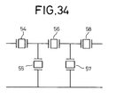
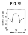
- A filter composed of surface
acoustic wave resonators 54 ~ 58 connected in a ladder configuration as shown in FIG. 34 has insertion loss vs. frequency characteristics as shown in FIG. 35. Such a ladder-type filter arrangement requires that the product of the admittance of the surfaceacoustic wave resonators acoustic wave resonators acoustic wave resonators acoustic wave resonators - As described above, if the transducers of the conventional interdigitated interdigital surface acoustic wave filters are withdrawal-weighted in order to suppress the side lobes, then the trap frequency band is increased, impairing the cutoff characteristics in the insertion loss vs. frequency characteristics.
- It has been customary to connect interdigitated interdigital surface acoustic wave filters in cascade for increasing the level of attenuation in stop bands. This approach is effective to increase the out-band attenuation levels, but also suffers an increased insertion loss in the passband.
- Filters composed of surface acoustic wave resonators connected in a ladder configuration require that a certain relationship be achieved between those surface acoustic wave resonators which are connected in series to each other and those surface acoustic wave resonators which are connected parallel to each other. As a result, the levels of attenuation in the stop bands remote from the passband are low, and there are certain limitations imposed on the passband and notch frequency. Higher attenuation levels outside of the passband sacrifice the insertion loss, i.e., cause an increase in the insertion loss.
- It is a first object of the present invention to provide a surface acoustic wave filter which allows impedance matching to be achieved easily even if the number of transducers is increased for a lower insertion loss, and which has better out-band insertion loss vs. frequency characteristics.
- A second object of the present invention is to provide a surface acoustic wave filter which is of a simple arrangement for lowering the level of a side lobe in a frequency range close to and higher than a passband, which side lobe is essentially developed by a two-port surface acoustic wave resonator filter.
- A third object of the present invention is to provide a composite surface acoustic wave filter which is free of limitations on the passband and notch frequency, has a lower insertion loss, and better insertion loss vs. frequency characteristics by increasing the levels of attenuation in frequency ranges higher and lower than the passband with the use of surface acoustic wave resonators.
- A fourth object of the present invention is to provide a mobile communication system which incorporates a composite surface acoustic wave filter of better insertion loss vs. frequency characteristics with surface acoustic wave resonators.
- To achieve the first object of the present invention, there is provided a composite surface acoustic wave filter comprising a surface acoustic wave filter having input and output terminals, and at least one surface acoustic wave resonator electrically connected in series to at least one of the input and output terminals of the surface acoustic wave filter. The surface acoustic wave resonator may have an antiresonant frequency in a stop band which is close to and higher than a passband of the surface acoustic wave filter. The surface acoustic wave filter may comprise an interdigitated interdigital surface acoustic wave filter comprising a plurality of input transducers electrically connected in parallel to each other, and a plurality of output transducers disposed between the input transducers and electrically connected in parallel to each other. Alternatively, the surface acoustic wave filter may comprise a two-port surface acoustic wave resonator filter. The surface acoustic wave resonator may comprise a one-port surface acoustic wave resonator. The surface acoustic wave filter and the surface acoustic wave resonator may be mounted on a substrate.
- To achieve the second object of the present invention, there is provided a composite surface acoustic wave filter comprising a surface acoustic wave filter having input and output terminals, and at least one surface acoustic wave resonator electrically connected parallel to at least one of the input and output terminals of the surface acoustic wave filter. The surface acoustic wave resonator may have a resonant frequency in a stop band which is close to and lower than a passband of the surface acoustic wave filter. The surface acoustic wave filter may comprise an interdigitated interdigital surface acoustic wave filter comprising a plurality of input transducers electrically connected parallel to each other, and a plurality of output transducers disposed between the input transducers and electrically connected parallel to each other. Alternatively, the surface acoustic wave filter may comprise a two-port surface acoustic wave resonator filter. The surface acoustic wave resonator may comprise a one-port surface acoustic wave resonator. The surface acoustic wave filter and the surface acoustic wave resonator may be mounted on the substrate.
- To achieve the third object of the present invention, there is provided a composite surface acoustic wave filter comprising a surface acoustic wave filter having input and output terminals, at least one first surface acoustic wave resonator electrically connected parallel to at least one of the input and output terminals of the surface acoustic wave filter, and at least one second surface acoustic wave resonator electrically connected in series to the surface acoustic wave filter. The first surface acoustic wave resonator may have a resonant frequency in a stop band which is close to and lower than a passband of the surface acoustic wave filter, and the second surface acoustic wave resonator may have an antiresonant frequency in a stop band which is close to and higher than the passband of the surface acoustic wave filter. The surface acoustic wave filter may comprise an interdigitated interdigital surface acoustic wave filter comprising a plurality of input transducers electrically connected parallel to each other, and a plurality of output transducers disposed between the input transducers and electrically connected parallel to each other. Alternatively, the surface acoustic wave filter may comprise a two-port surface acoustic wave resonator filter. Each of the first and second surface acoustic wave resonators may comprise a one-port surface acoustic wave resonator. The surface acoustic wave filter and the first and second surface acoustic wave resonators may be mounted on the substrate.
- To achieve the fourth object of the present invention, there is provided a mobile communication system including filters in an antenna sharing unit and interstage filters, each of the filters and the interstage filters comprising any one of the composite acoustic surface wave filters described above.
- The above and other objects, features, and advantages of the present invention will become apparent from the following description when taken in conjunction with the accompanying drawings which illustrate preferred embodiments of the present invention by way of example.
-
- FIG. 1 is a schematic plan view of an interdigitated interdigital surface acoustic wave filter according to a first embodiment of the present invention;
- FIG. 2 is a diagram showing insertion loss vs. frequency characteristics of the interdigitated interdigital surface acoustic wave filter according to the first embodiment;
- FIG. 3 is a schematic plan view of a surface acoustic wave filter according to a second embodiment of the present invention;
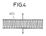
- FIG. 4 is a schematic plan view of a one-port surface acoustic wave resonator incorporated in the surface acoustic wave filter according to the second embodiment;
- FIG. 5 is a diagram showing the input impedance of the one-port surface acoustic wave resonator in the second embodiment;
- FIG. 6 is a diagram showing insertion loss vs. frequency characteristics of the surface acoustic wave filter according to the second embodiment;
- FIG. 7 is a schematic plan view of a surface acoustic wave filter according to a third embodiment of the present invention;
- FIG. 8 is a diagram showing insertion loss vs. frequency characteristics of the surface acoustic wave filter according to the third embodiment;
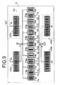
- FIG. 9 is a schematic plan view of a composite surface acoustic wave filter according to a fourth embodiment of the present invention;
- FIG. 10 is a diagram showing insertion loss vs. frequency characteristics of the composite surface acoustic wave filter according to the fourth embodiment;
- FIG. 11 is a schematic plan view of a composite surface acoustic wave filter according to a fifth embodiment of the present invention;
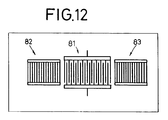
- FIG. 12 is a schematic plan view of a one-port surface acoustic wave resonator with reflectors which may be employed in the fourth and fifth embodiments;
- FIG. 13 is a schematic plan view of a composite surface acoustic wave filter according to a sixth embodiment of the present invention;
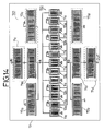
- FIG. 14 is a schematic plan view of a composite surface acoustic wave filter according to a seventh embodiment of the present invention;
- FIG. 15 is a diagram showing insertion loss vs. frequency characteristics of the composite surface acoustic wave filter according to the seventh embodiment;
- FIG. 16 is a schematic plan view of a composite surface acoustic wave filter according to an eighth embodiment of the present invention;
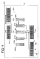
- FIG. 17 is a schematic plan view of a composite surface acoustic wave filter according to a ninth embodiment of the present invention;
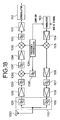
- FIG. 18 is a block diagram of a portion of a mobile communication system which incorporates a composite surface acoustic wave filter according to the present invention;
- FIG. 19 is a schematic plan view of a conventional interdigitated interdigital surface acoustic wave filter with 5 transducers;
- FIG. 20A is a diagram showing calculated impedances on input transducers of the interdigitated interdigital surface acoustic wave filter with normal transducers shown in FIG. 19;
- FIG. 20B is a diagram showing calculated impedances on output transducers of the interdigitated interdigital surface acoustic wave filter with normal transducers shown in FIG. 19;
- FIG. 21A is a circuit diagram of a matching circuit for the interdigitated interdigital surface acoustic wave filter shown in FIG. 19;
- FIG. 21B is a circuit diagram of a matching circuit for an interdigitated interdigital surface acoustic wave filter shown in FIG. 22;
- FIG. 22 is a schematic plan view of a conventional interdigitated interdigital surface acoustic wave filter with 13 transducers;
- FIG. 23A is a diagram showing calculated impedances on input transducers of the interdigitated interdigital surface acoustic wave filter shown in FIG. 22;
- FIG. 23B is a diagram showing calculated impedances on output transducers of the interdigitated interdigital surface acoustic wave filter shown in FIG. 22;
- FIG. 24 is a diagram showing insertion loss vs. frequency characteristics of the interdigitated interdigital surface acoustic wave filter shown in FIG. 22 which is combined with the matching circuit shown in FIG. 21B;
- FIG. 25 is a schematic plan view of a conventional interdigitated interdigital surface acoustic wave filter with 13 different withdrawal-weighted transducers;
- FIG. 26 is a diagram showing insertion loss vs. frequency characteristics of the interdigitated interdigital surface acoustic wave filter shown in FIG. 25 which is combined with the matching circuit shown in FIG. 21B;
- FIG. 27 is a schematic plan view of a conventional transducer with an increased number of electrode finger pairs;
- FIG. 28 is a diagram showing impedance vs. frequency characteristics of the transducer shown in FIG. 27;
- FIG. 29 is a schematic plan view of a conventional two-port surface acoustic wave resonator filter;
- FIG. 30 is a diagram showing insertion loss vs. frequency characteristics of the two-port surface acoustic wave resonator filter shown in FIG. 29;
- FIG. 31 is a schematic plan view of two cascaded two-port surface acoustic wave resonator filters shown in FIG. 29;
- FIG. 32 is a schematic plan view of another conventional two-port surface acoustic wave resonator filter;
- FIG. 33 is a diagram showing insertion loss vs. frequency characteristics of the two-port surface acoustic wave resonator filter shown in FIG. 32;
- FIG. 34 is a diagram of a conventional filter composed of surface acoustic wave resonators connected in a ladder configuration; and
- FIG. 35 is a diagram showing insertion loss vs. frequency characteristics of the filter shown in FIG. 34.
- As shown in FIG. 1, an interdigitated interdigital surface
acoustic wave filter 101 according to a first embodiment of the present invention comprises an interdigitated interdigital surfaceacoustic wave filter 2 mounted on asubstrate 5. The interdigitated interdigital surfaceacoustic wave filter 2 has 13 different withdrawal-weighted transducers includinginput transducers 3₁ ~ 3₇ andoutput transducers 4₁ ~ 4₆. - The interdigitated interdigital surface
acoustic wave filter 101 also includes a pair oftransducers substrate 5 and connected respectively to input and output terminals of the interdigitated interdigital surfaceacoustic wave filter 2. Thetransducers - FIG. 2 shows insertion loss vs. frequency characteristics of the interdigitated interdigital surface
acoustic wave filter 101 with matching circuits shown in FIG. 21A being connected to the respective input and output terminals thereof. Comparison between the insertion loss vs. frequency characteristics shown in FIG. 2 and those shown in FIGS. 24 and 26 clearly indicates that the interdigitated interdigital surfaceacoustic wave filter 101 has reduced side lobes outside of the passband and improved attenuation characteristics. - The
transducers transducers acoustic wave filter 2, and thetransducers acoustic wave filter 101 does not require the series capacitance of a matching circuit which is necessitated by increasing the number of transducers for a lower insertion loss. If the notch filters were composed of thetransducers - Heretofore, as shown in FIG. 21B, a matching circuit is required to be composed of two capacitive elements and two inductive elements, and the attenuation in the vicinity of the passband in the insertion loss vs. frequency characteristics is low as shown in FIG. 26. In this embodiment, however, a matching circuit may be composed of two inductive elements, and the insertion loss vs. frequency characteristics are better as shown in FIG. 2.
- A resonator comprising reflectors disposed one on each side of each of the
transducers - FIG. 3 shows a surface acoustic wave filter according to a second embodiment of the present invention.
- The surface acoustic wave filter, generally designated by the
reference numeral 201 in FIG. 3, comprises a two-port surface acousticwave resonator filter 202 comprising aninput transducer 203, twooutput transducers input transducer 203, a reflector 205a disposed outside of theoutput transducer 204a, and areflector 205b disposed outside of theoutput transducer 204b, a one-port surfaceacoustic wave resonator 207a disposed on an input terminal side of the two-port surface acousticwave resonator filter 202, and a one-port surfaceacoustic wave resonator 207b disposed on an output terminal side of the two-port surface acousticwave resonator filter 202. The one-port surfaceacoustic wave resonator 207a is electrically connected in series to an input terminal of the two-port surface acousticwave resonator filter 202, so that an input signal can be supplied through the one-port surfaceacoustic wave resonator 207a to the input terminal of the two-port surface acousticwave resonator filter 202. The one-port surfaceacoustic wave resonator 207b is electrically connected in series to output terminals of theoutput transducers wave resonator filter 202, so that an output signal can be outputted through the one-port surfaceacoustic wave resonator 207b. The two-port surface acousticwave resonator filter 202 and the one-port surfaceacoustic wave resonators - The input impedance of a one-port surface acoustic wave resonator 6 (7) shown in FIG. 4, which is equivalent to the
transducer acoustic wave resonator acoustic wave resonators wave resonator filter 202, provide a stop band in the vicinity of their antiresonant frequencies. - The one-port surface
acoustic wave resonators wave resonator filter 202. - Therefore, while the two-port surface acoustic
wave resonator filter 202 has insertion loss vs. frequency characteristics equal to the insertion loss vs. frequency characteristics shown in FIG. 30, the antiresonant frequencies of the one-port surfaceacoustic wave resonators wave resonator filter 202 is greatly reduced. The surfaceacoustic wave filter 201 according to the second embodiment thus has insertion loss vs. frequency characteristics as shown in FIG. 6, and any increase in its insertion loss is almost eliminated. - Since the one-port surface
acoustic wave resonators wave resonator filter 202, the level of the side lobe which is produced in a range close to and higher than the passband of the conventional two-port surface acousticwave resonator filter 20 is lowered in its full range, thereby providing sufficient attenuation characteristics. - The one-port surface
acoustic wave resonators wave resonator filter 202 from varying in its passband. Setting the electrostatic capacitances to suitable values is equivalent to electrically connecting electrostatic capacitive elements in series to the two-port surface acousticwave resonator filter 202 in the passband thereof. Thus, these one-port surfaceacoustic wave resonators wave resonator filter 202 can therefore be designed with greater freedom. - The insertion loss vs. frequency characteristics shown in FIG. 6 can also be obtained by connecting the one-port surface
acoustic wave resonators wave resonator filter 20 shown in FIG. 29 which was designed without a matching circuit in a 50 Ω-impedance arrangement. - FIG. 7 illustrates a surface acoustic wave filter according to a third embodiment of the present invention.
- As shown in FIG. 7, the surface acoustic wave filter, generally designated by the
reference numeral 301, comprises a two-port surface acousticwave resonator filter 310 comprising aninput transducer 303, anoutput transducer 304, areflector 305a disposed outside of theinput transducer 303, and areflector 305b disposed outside of theoutput transducer 304, a one-port surfaceacoustic wave resonator 308a electrically connected in series to an input terminal of the two-port surface acousticwave resonator filter 310 for supplying an input signal through the one-port surfaceacoustic wave resonator 308a to the two-port surface acousticwave resonator filter 310, a one-port surfaceacoustic wave resonator 308b electrically connected in series to an output terminal of the two-port surface acousticwave resonator filter 310, and a one-port surfaceacoustic wave resonator 308c electrically connected in series to an output terminal of the one-port surfaceacoustic wave resonator 308b for outputting an output signal through the one-port surfaceacoustic wave resonator 308c. The two-port surface acousticwave resonator filter 310 and the one-port surfaceacoustic wave resonators - The one-port surface
acoustic wave resonators wave resonator filter 310. - Therefore, while the two-port surface acoustic
wave resonator filter 310 is the same as the two-port surface acousticwave resonator filter 50 shown in FIG. 32 and has insertion loss vs. frequency characteristics equal to the insertion loss vs. frequency characteristics shown in FIG. 33, the antiresonant frequencies of the one-port surfaceacoustic wave resonators wave resonator filter 310 is greatly reduced. The surfaceacoustic wave filter 301 according to the third embodiment thus has insertion loss vs. frequency characteristics as shown in FIG. 8, and any increase in its insertion loss is almost eliminated. - In the third embodiment, the three one-port surface
acoustic wave resonators wave resonator filter 310 is relatively wide. The insertion loss vs. frequency characteristics shown in FIG. 33 are produced by the two-port surface acousticwave resonator filter 50 with no matching circuit. The insertion loss vs. frequency characteristics shown in FIG. 8 are obtained when inductive elements are connected as a matching circuit parallel to the two-port surface acousticwave resonator filter 310. - Formation of the two-port surface acoustic wave resonator filter and the one-port surface acoustic wave resonators in each of the second and third embodiments allows their antiresonant frequencies to differ from each other by the same range.
- In each of the above embodiments, the two-port surface acoustic wave resonator filter and the one-port surface acoustic wave resonators are formed on one substrate. However, the two-port surface acoustic wave resonator filter and the one-port surface acoustic wave resonators may be formed on different substrates for greater design freedom.
- In each of the above embodiments, the one-port surface acoustic wave resonators have different antiresonant frequencies and are electrically connected in series to the two-port surface acoustic wave resonator filter. However, the one-port surface acoustic wave resonators may have the same antiresonant frequency and be electrically connected in series to the two-port surface acoustic wave resonator filter for a higher impedance to achieve more design flexibility.
- While in each of the above embodiments the plural one-port surface acoustic wave resonators are electrically connected in series to the two-port surface acoustic wave resonator filter, only one one-port surface acoustic wave resonators may be electrically connected in series to the two-port surface acoustic wave resonator filter for effectively reducing the side lobe level insofar as the frequency range of the side lobe close to and higher than the passband is relatively narrow.
- In each of the above embodiments, each of the one-port surface acoustic wave resonators comprises an transducer only. However, each of the one-port surface acoustic wave resonators may be combined with reflectors disposed one on each side thereof.
- If there is a side lobe existing in a range close to and lower than the passband of the two-port surface acoustic wave resonator filter, one or more one-port surface acoustic wave resonator having an antiresonant frequency in a range close to and lower than the passband may be electrically connected in series to the input or output terminal transducer of the two-port surface acoustic wave resonator filter.
- FIG. 9 shows a composite surface acoustic wave filter according to a fourth embodiment of the present invention.
- As shown in FIG. 9, the composite surface acoustic wave filter, generally designated by the
reference numeral 401, comprises an interdigitated interdigital surfaceacoustic wave filter 410 comprising a plurality of different withdrawal-weighted input transducers substrate 13 and a plurality of different withdrawal-weighted output transducers substrate 13, theinput transducers output transducers acoustic wave filter 401 also includes a one-port surfaceacoustic wave resonator 405a electrically connected parallel to the inter-digitated interdigital surfaceacoustic wave filter 410 through an input terminal A thereof, and a one-port surfaceacoustic wave resonator 405b electrically connected parallel to the interdigitated interdigital surfaceacoustic wave filter 410 through an output terminal B thereof. The one-port surfaceacoustic wave resonators substrate 13. - The interdigitated interdigital surface
acoustic wave filter 410 are identical to the interdigitated interdigital surfaceacoustic wave filter 2 shown in FIG. 1. The one-port surfaceacoustic wave resonators acoustic wave resonators - The impedance of the one-port surface
acoustic wave resonators acoustic wave resonators - If only the one-port surface
acoustic wave resonators acoustic wave resonators - In the composite surface
acoustic wave filter 401, the one-port surfaceacoustic wave resonators acoustic wave filter 410 parallel thereto. With this arrangement, the composite surfaceacoustic wave filter 401 provides a stop band in the vicinity of the resonant frequency because the impedance of the one-port surfaceacoustic wave resonators acoustic wave resonators acoustic wave filter 401 thus remains substantially unchanged. - In the fourth embodiment, the pitch of electrode fingers of the one-port surface
acoustic wave resonators acoustic wave resonators acoustic wave filter 410, and also to bring the antiresonant frequencies of the one-port surfaceacoustic wave resonators acoustic wave filter 410. With such resonant and antiresonant frequency settings, since the impedance of the one-port surfaceacoustic wave resonators acoustic wave resonators acoustic wave filter 410. Inasmuch as the impedance of the one-port surfaceacoustic wave resonators acoustic wave filter 410, thus improving the attenuation characteristics which are impaired by the withdrawal weighting of the transducers of the interdigitated interdigital surfaceacoustic wave filter 410. - FIG. 10 shows insertion loss vs. frequency characteristics of the interdigitated interdigital surface
acoustic wave filter 410. As shown in FIG. 10, the attenuation level in the stop band of the composite surfaceacoustic wave filter 401, which is of 35 dB, is improved about 20 dB and the trap frequency range is reduced by the two one-port surfaceacoustic wave resonators acoustic wave filter 410. The composite surfaceacoustic wave filter 401 can thus achieve the same attenuation level as is the case with the conventional arrangement in which interdigitated interdigital surface acoustic wave filters are connected in cascade. - The one-port surface
acoustic wave resonators acoustic wave resonators acoustic wave filter 410 may be reduced, and hence the size of the inductive elements may also be reduced. - If the number of transducers and the pitch of electrode fingers of the interdigitated interdigital surface
acoustic wave filter 410 are selected to design the interdigitated interdigital surfaceacoustic wave filter 410 such that capacitive elements are required to be connected as a matching circuit parallel to the interdigitated interdigital surfaceacoustic wave filter 410, then the electrostatic capacitance of such capacitive elements may be reduced because of the electrostatic capacitance of the one-port surfaceacoustic wave resonators acoustic wave resonators acoustic wave filter 410. - In the fourth embodiment, if the one-port surface
acoustic wave resonators acoustic wave filter 410 becomes deep. The resonant and antiresonant frequencies of the one-port surfaceacoustic wave resonators acoustic wave resonators acoustic wave resonators acoustic wave filter 410 is increased. - Since the one-port surface
acoustic wave resonators acoustic wave filter 410 are formed on thesame substrate 13, as described above, any stray capacitance which would be introduced by interconnections between the one-port surfaceacoustic wave resonators acoustic wave filter 410 is minimized. The relationships between the resonant frequencies of the one-port surfaceacoustic wave resonators acoustic wave filter 410 are the same as each other, and the frequency errors and temperature characteristics of the one-port surfaceacoustic wave resonators acoustic wave filter 410. Consequently, the differences between the cutoff frequency and the resonant and antiresonant frequencies due to the frequency errors at the time the composite surfaceacoustic wave filter 401 is manufactured are relatively small. As the area of the chip on which the composite surfaceacoustic wave filter 401 is fabricated is not large, the composite surfaceacoustic wave filter 401 is relatively inexpensive. The same advantages as described above can be achieved even if one of the one-port surfaceacoustic wave resonators - As indicated by the broken lines in FIG. 9, one-port surface
acoustic wave resonators acoustic wave resonators acoustic wave resonators acoustic wave filter 410 becomes deeper. If the resonant frequencies of the one-port surfaceacoustic wave resonators acoustic wave filter 410 is increased. - A composite surface acoustic wave filter according to a fifth embodiment of the present invention is shown in FIG. 11.
- As shown in FIG. 11, the composite surface acoustic wave filter, generally designated by the
reference numeral 501, comprises an interdigitated interdigital surfaceacoustic wave filter 510 and two one-port surfaceacoustic wave resonators substrate 13. The one-port surfaceacoustic wave resonators acoustic wave filter 510 at an output terminal B thereof. The one-port surfaceacoustic wave resonators - As shown in FIG. 5, the impedance of the one-port surface
acoustic wave resonators - The resonant frequencies of the one-port surface
acoustic wave resonators acoustic wave filter 510, and also the antiresonant frequencies of the one-port surfaceacoustic wave resonators acoustic wave filter 510. With such resonant and antiresonant frequency settings, since the impedance of the one-port surfaceacoustic wave resonators acoustic wave resonators acoustic wave filter 510. Since the impedance of the one-port surfaceacoustic wave resonators acoustic wave filter 510, thus improving the attenuation characteristics which are impaired by the withdrawal weighting of the transducers of the interdigitated interdigital surfaceacoustic wave filter 510. - Since the one-port surface
acoustic wave resonators - If the one-port surface
acoustic wave resonators acoustic wave resonators acoustic wave resonators acoustic wave resonators acoustic wave filter 510 is increased. In this case, there is no increase in the insertion loss in the vicinity of the antiresonant frequency in the passband. - In the fourth and fifth embodiments, the one-port surface
acoustic wave resonators acoustic wave resonators transducer 81 and a pair ofreflectors transducer 81. - FIG. 13 illustrates a composite surface acoustic wave filter according to a sixth embodiment of the present invention.
- As shown in FIG. 13, the composite surface acoustic wave filter, generally designated by the
reference numeral 601, comprises a two-port surface acoustic wave resonator filter 640 composed of aninput transducer 641, twooutput transducers input transducer 641 and electrically connected parallel to theinput transducer 641, and tworeflectors respective output transducers input transducer 641, and a one-port surfaceacoustic wave resonator 605b electrically connected parallel to the two-port surface acoustic wave resonator filter 640 at an output terminal D thereof. The two-port surface acoustic wave resonator filter 640 and the one-port surfaceacoustic wave resonator 605b are formed on asubstrate 13. The two-port surface acoustic wave resonator filter 640 has essentially the same insertion loss vs. frequency characteristics as those of the interdigitated interdigital surface acoustic wave filters 410, 510. - The insertion loss vs. frequency characteristics of the composite surface
acoustic wave filter 601 are improved by selecting the resonant frequency of the one-port surfaceacoustic wave resonator 605b to be in the stop band close to and lower than the passband of the two-port surface acoustic wave resonator filter 640. - In the fourth through sixth embodiments, the resonant frequencies of the one-port surface
acoustic wave resonators 405a ~ 405d, 507a, 507b, 605b are selected to be in the stop bands close to and lower than the passbands of the interdigitated interdigital surface acoustic wave filters 410, 510 and the two-port surface acoustic wave resonator filter 640. However, the resonant frequencies of the one-port surfaceacoustic wave resonators 405a ~ 405d, 507a, 507b, 605b may be selected to be in a frequency band where a side lobe exists, lower than the passbands of the interdigitated interdigital surface acoustic wave filters 410, 510 and the two-port surface acoustic wave resonator filter 640, for thereby suppressing the side lobe in the frequency range lower than the passband. - FIG. 14 shows a composite surface acoustic wave filter according to a seventh embodiment of the present invention.
- As shown in FIG. 14, the composite surface acoustic wave filter, generally designated by the
reference numeral 701, comprises an interdigitated interdigital surfaceacoustic wave filter 710 with different withdrawal-weighted transducers, a one-port surfaceacoustic wave resonator 71a electrically connected in series to the interdigitated interdigital surfaceacoustic wave filter 710 at an input terminal A thereof, a one-port surfaceacoustic wave resonator 71b electrically connected in series to the interdigitated interdigital surfaceacoustic wave filter 710 at an output terminal B thereof, a one-port surfaceacoustic wave resonator 72a electrically connected parallel to the interdigitated interdigital surfaceacoustic wave filter 710 at the input terminal A thereof, and a one-port surfaceacoustic wave resonator 72b electrically connected parallel to the interdigitated interdigital surfaceacoustic wave filter 710 at the output terminal B thereof. The interdigitated interdigital surfaceacoustic wave filter 710 and the one-port surfaceacoustic wave resonators substrate 13. - The interdigitated interdigital surface
acoustic wave filter 710 with different withdrawal-weighted transducers is identical to the interdigitated interdigital surfaceacoustic wave filter 410 shown in FIG. 9. The one-port surfaceacoustic wave resonators - The impedance of the one-port surface
acoustic wave resonators acoustic wave resonators - If only the one-port surface
acoustic wave resonators acoustic wave resonators - In the composite surface
acoustic wave filter 701, the one-port surfaceacoustic wave resonators acoustic wave filter 710 in series thereto. With this arrangement, the composite surfaceacoustic wave filter 701 provides a stop band in the vicinity of the antiresonant frequency because the impedance of the one-port surfaceacoustic wave resonators acoustic wave resonators acoustic wave filter 701 thus remains substantially unchanged. - In the composite surface
acoustic wave filter 701, the one-port surfaceacoustic wave resonators acoustic wave filter 710 parallel thereto. With this arrangement, the composite surfaceacoustic wave filter 701 provides a stop band in the vicinity of the resonant frequency because the impedance of the one-port surfaceacoustic wave resonators acoustic wave resonators acoustic wave filter 701 thus remains substantially unchanged. - In the seventh embodiment, the pitch of electrode fingers of the one-port surface
acoustic wave resonators acoustic wave resonators acoustic wave filter 710, and also to bring the resonant frequencies of the one-port surfaceacoustic wave resonators acoustic wave filter 710. Similarly, the pitch of electrode fingers of the one-port surfaceacoustic wave resonators acoustic wave resonators acoustic wave filter 710, and also to bring the antiresonant frequencies of the one-port surfaceacoustic wave resonators acoustic wave filter 710. With such resonant and antiresonant frequency settings, since the impedance of the one-port surfaceacoustic wave resonators acoustic wave resonators acoustic wave filter 710. Because the impedance of the one-port surfaceacoustic wave resonators acoustic wave resonators acoustic wave filter 710. - Inasmuch as the impedance of the one-port surface
acoustic wave resonators acoustic wave filter 710, and also inasmuch as the impedance of the one-port surfaceacoustic wave resonators acoustic wave filter 710, thus improving the attenuation characteristics which are impaired by the withdrawal weighting of the transducers of the interdigitated interdigital surfaceacoustic wave filter 710. - FIG. 15 shows insertion loss vs. frequency characteristics of the composite surface
acoustic wave filter 701 with inductive elements connected as a matching circuit parallel to the interdigitated interdigital surfaceacoustic wave filter 710. As shown in FIG. 15, the attenuation level in the stop bands close to and higher and lower than the passband of the composite surfaceacoustic wave filter 701 is of 35 dB. The attenuation level in the stop band close to and lower than the passband is improved about 15 dB and the attenuation level in the stop band close to and higher than the passband is improved about 20 dB, and the trap frequency range is reduced by the one-port surfaceacoustic wave resonators acoustic wave filter 710. The composite surfaceacoustic wave filter 701 can thus achieve the same attenuation level as is the case with the conventional arrangement in which interdigitated interdigital surface acoustic wave filters are connected in cascade. - The one-port surface
acoustic wave resonators acoustic wave resonators acoustic wave filter 710 may be reduced, and hence the size of the inductive elements may also be reduced. - If the number of transducers and the pitch of electrode fingers of the interdigitated interdigital surface
acoustic wave filter 710 are selected to design the interdigitated interdigital surfaceacoustic wave filter 710 such that capacitive elements are required to be connected as a matching circuit parallel to the interdigitated interdigital surfaceacoustic wave filter 710, then the electrostatic capacitance of such capacitive elements may be reduced because of the electrostatic capacitance of the one-port surfaceacoustic wave resonators acoustic wave resonators acoustic wave filter 710. If a matching circuit needs to be connected in series to the interdigitated interdigital surfaceacoustic wave filter 710, such a matching circuit may partly or wholly be dispensed with due to the electrostatic capacitance of the one-port surfaceacoustic wave resonators - In the seventh embodiment, if the one-port surface
acoustic wave resonators acoustic wave filter 710 becomes deep. If the pitch of electrode fingers of the one-port surfaceacoustic wave resonators acoustic wave filter 710 is increased. - Since the one-port surface
acoustic wave resonators acoustic wave filter 710 are formed on thesame substrate 13, as described above, any stray capacitance which would be introduced by interconnections between the one-port surfaceacoustic wave resonators acoustic wave filter 710 is minimized. The relationships between the antiresonant frequencies of the one-port surfaceacoustic wave resonators acoustic wave filter 710 are the same as each other, and the relationships between the resonant frequencies of the one-port surfaceacoustic wave resonators acoustic wave filter 710 are the same as each other. The frequency errors and temperature characteristics of the one-port surfaceacoustic wave resonators acoustic wave filter 710. Consequently, the differences between the cutoff frequency and the resonant and antiresonant frequencies due to the frequency errors at the time the composite surfaceacoustic wave filter 701 is manufactured are relatively small. As the area of the chip on which the composite surfaceacoustic wave filter 701 is fabricated is not large, the composite surfaceacoustic wave filter 701 is relatively inexpensive. The same advantages as described above can be achieved even if one of the one-port surfaceacoustic wave resonators acoustic wave resonators - As indicated by the broken lines in FIG. 14, one-port surface
acoustic wave resonators acoustic wave resonators acoustic wave resonators acoustic wave filter 710 becomes deeper. If the antiresonant frequencies of the one-port surfaceacoustic wave resonators acoustic wave filter 710 is increased. - Likewise, as indicated by the broken lines in FIG. 14, one-port surface
acoustic wave resonators acoustic wave resonators acoustic wave resonators acoustic wave filter 710 becomes deeper. If the resonant frequencies of the one-port surfaceacoustic wave resonators acoustic wave filter 710 is increased. - In the seventh embodiment, the one-port surface
acoustic wave resonator 72a is connected parallel to the transducers of the interdigitated interdigital surfaceacoustic wave filter 710. However, the one-port surfaceacoustic wave resonator 72a may be connected parallel to the input terminal IN. Similarly, while the one-port surfaceacoustic wave resonator 72b is connected parallel to the transducers of the interdigitated interdigital surfaceacoustic wave filter 710, the one-port surfaceacoustic wave resonator 72a may be connected parallel to the output terminal OUT. - FIG. 16 shows a composite surface acoustic wave filter according to an eighth embodiment of the present invention.
- As shown in FIG. 16, the composite surface acoustic wave filter, generally designated by the
reference numeral 801, comprises an interdigitated interdigital surfaceacoustic wave filter 810 with different withdrawal-weighted transducers and one-port surfaceacoustic wave resonators substrate 13. The one-port surfaceacoustic wave resonator 71a is electrically connected in series to the interdigitated interdigital surfaceacoustic wave filter 810 at an input terminal A thereof. The one-port surfaceacoustic wave resonator 71b is electrically connected in series to the interdigitated interdigital surfaceacoustic wave filter 810 at an output terminal B thereof. The one-port surfaceacoustic wave resonator 72c is electrically connected parallel to the interdigitated interdigital surfaceacoustic wave filter 810 at the input terminal A thereof. The one-port surfaceacoustic wave resonator 72e is electrically connected parallel to the interdigitated interdigital surfaceacoustic wave filter 810 at an input terminal IN of the composite surfaceacoustic filter 801. The one-port surfaceacoustic wave resonators acoustic filter 801 and the input terminal A of the interdigitated interdigital surfaceacoustic wave filter 810. - The interdigitated interdigital surface
acoustic wave filter 810 is identical to the interdigitated interdigital surfaceacoustic wave filter 710 shown in FIG. 14. The one-port surfaceacoustic wave resonators - The impedance of the one-port surface
acoustic wave resonators - The antiresonant frequencies of the one-port surface
acoustic wave resonators acoustic wave filter 810, and the resonant frequencies thereof are selected to be in the passband of the interdigitated interdigital surfaceacoustic wave filter 810. The resonant frequencies of the one-port surfaceacoustic wave resonators acoustic wave filter 810, and the antiresonant frequencies thereof are selected to be in the passband of the interdigitated interdigital surfaceacoustic wave filter 810. - With such resonant and antiresonant frequency settings, since the impedance of the one-port surface
acoustic wave resonators acoustic wave filter 810. Because the impedance of the one-port surfaceacoustic wave resonators acoustic wave filter 810. - Since the impedance of the one-port surface
acoustic wave resonators acoustic wave filter 810. Because the impedance of the one-port surfaceacoustic wave resonators acoustic wave filter 810. - If the one-port surface
acoustic wave resonators acoustic wave resonators acoustic wave resonators acoustic wave resonators acoustic wave filter 801 operates in the same manner as with the seventh embodiment described above. - Therefore, the attenuation characteristics which are impaired by the withdrawal weighting of the transducers of the interdigitated interdigital surface
acoustic wave filter 810 are improved. - In the seventh and eighth embodiments, the one-port surface
acoustic wave resonators 71a ~ 71d, 72a ~ 72e are arranged as shown in FIG. 4. However, as shown in FIG. 12, each of the one-port surfaceacoustic wave resonators 71a ~ 71d, 72a ~ 72e may be composed of thetransducer 81 and the pair ofreflectors transducer 81. - FIG. 17 illustrates a composite surface acoustic wave filter according to a ninth embodiment of the present invention.
- As shown in FIG. 17, the composite surface acoustic wave filter, generally designated by the
reference numeral 901, comprises a two-port surface acousticwave resonator filter 940 composed of aninput transducer 941, twooutput transducers input transducer 941 and electrically connected parallel to theinput transducer 941, and tworeflectors respective output transducers input transducer 941, a one-port surfaceacoustic wave resonator 71a electrically connected in series to the two-port surfaceacoustic wave filter 940 at an input terminal C thereof, a one-port surfaceacoustic wave resonator 72a electrically connected parallel to the two-port surfaceacoustic wave filter 940 at the input terminal C thereof, a one-port surfaceacoustic wave resonator 71b electrically connected in series to the two-port surfaceacoustic wave filter 940 at an output terminal D thereof, and a one-port surfaceacoustic wave resonator 72b electrically connected parallel to the two-port surfaceacoustic wave filter 940 at the output terminal D thereof. The two-port surfaceacoustic wave filter 940 and the one-port surfaceacoustic wave resonators substrate 13. The two-port surfaceacoustic wave filter 940 has insertion loss vs. frequency characteristics which are the same as the interdigitated interdigital surfaceacoustic wave filter 10. - The insertion loss vs. frequency characteristics of the composite surface
acoustic wave filter 901 are improved by bringing the antiresonant frequencies of the one-port surfaceacoustic wave resonators acoustic wave filter 940, and also by bringing the resonant frequencies of the one-port surfaceacoustic wave resonators acoustic wave filter 940. - In the seventh through ninth embodiments, the resonant frequencies of the one-port surface
acoustic wave resonators 72a ~ 72e are selected to be in the stop bands close to and lower than the passbands of the interdigitated interdigital surface acoustic wave filters 710, 810 and the two-port surfaceacoustic wave filter 940. However, the resonant frequencies of the one-port surfaceacoustic wave resonators 72a ~ 72e may be selected to be in a frequency band where a side lobe exists, lower than the passbands of the interdigitated interdigital surface acoustic wave filters 710, 810 and the two-port surface acousticwave resonator filter 940, for thereby suppressing the side lobe in the frequency range lower than the passband. - Similarly, in the seventh through ninth embodiments, the antiresonant frequencies of the one-port surface
acoustic wave resonators 71a ~ 71d are selected to be in the stop bands close to and higher than the passbands of the interdigitated interdigital surface acoustic wave filters 710, 810 and the two-port surfaceacoustic wave filter 940. However, the antiresonant frequencies of the one-port surfaceacoustic wave resonators 71a ~ 71d may be selected to be in a frequency band where a side lobe exists, higher than the passbands of the interdigitated interdigital surface acoustic wave filters 710, 810 and the two-port surface acousticwave resonator filter 940, for thereby suppressing the side lobe in the frequency range higher than the passband. - An application of a composite surface acoustic wave filter according to the present invention will be described below.
- FIG. 18 shows a portion of a mobile communication system which incorporates a composite surface acoustic wave filter according to the present invention.
- The mobile communication system includes a double-conversion receiver. In the receiver, an output signal from an
antenna 1090 is limited to a certain frequency band by abandpass filter 1091 of anantenna sharing unit 1110, and then amplified by anRF amplifier 1092. The amplified signal is supplied to abandpass filter 1093 for noise suppression, after which the signal is mixed with a signal having a first local frequency by amixer 1096 for conversion into a first intermediate frequency signal. The first local frequency signal is supplied from afrequency synthesizer 1094 through abandpass filter 1095. The first intermediate frequency signal is supplied to abandpass filter 1097 which suppresses noise contained in the signal. Then, the first intermediate frequency signal is supplied to and amplified by a firstintermediate frequency amplifier 1098. The amplified first intermediate frequency signal is then mixed with a signal having a second local frequency from thefrequency synthesizer 1094 by amixer 1099 for conversion into a second intermediate frequency signal. The second intermediate frequency signal is supplied to abandpass filter 1100 which suppresses noise contained in the signal. Then, the second intermediate frequency signal is supplied to and amplified by a secondintermediate frequency amplifier 1101. The amplified first intermediate frequency signal is demodulated by ademodulator 1102 into a demodulated signal, which is sent to a following circuit stage. - The mobile communication system also has a transmitter in which a carrier from the
frequency synthesizer 1094 is modulated with an audio signal by amodulator 1103. The modulated signal from themodulator 1103 is then amplified by an amplifier 1104, which supplies the amplified signal to amixer 1105. Themixer 1105 converts the supplied signal into an excitation signal with a local transmission frequency signal from thefrequency synthesizer 1094. The excitation signal is amplified by anamplifier 1106 and limited to a certain frequency band by abandpass filter 1107. The signal is then amplified by apower amplifier 1108, and transmitted from theantenna 1090 through abandpass filter 1109 of theantenna sharing unit 1101. - The mobile communication system has transmission and reception signal frequency ranges that are close to each other. Therefore, the bandpass filters are required to have sharp cutoff characteristics and be small in size. Each of the
bandpass filters antenna sharing unit 1110, theinterstage bandpass filters bandpass filter 1095 for supplying the first local frequency signal therethrough from thefrequency synthesizer 1094 to themixer 1096 is composed of any of the composite surface acoustic wave filters 401 through 901 according to the fourth through ninth embodiments of the present invention. The bandpass filters 1091, 1109, 1093, 1107, 1095 thus constructed meet the requirements for sharp cutoff characteristics and small size. - Although certain preferred embodiments of the present invention has been shown and described in detail, it should be understood that various changes and modifications may be made therein without departing from the scope of the appended claims.
Claims (19)
- A composite surface acoustic wave filter comprising:
a surface acoustic wave filter having input and output terminals; and
at least one surface acoustic wave resonator electrically connected in series to at least one of the input and output terminals of said surface acoustic wave filter. - A composite surface acoustic wave filter according to claim 1, wherein said surface acoustic wave resonator has an antiresonant frequency in a stop band which is close to and higher than a passband of said surface acoustic wave filter.
- A composite surface acoustic wave filter according to claim 1, wherein said surface acoustic wave filter comprises an interdigitated interdigital surface acoustic wave filter comprising a plurality of input transducers electrically connected in parallel to each other, and a plurality of output transducers disposed between said input transducers and electrically connected in parallel to each other.
- A composite surface acoustic wave filter according to claim 1, wherein said surface acoustic wave filter comprises a two-port surface acoustic wave resonator filter.
- A composite surface acoustic wave filter according to claim 1, wherein said surface acoustic wave resonator comprises a one-port surface acoustic wave resonator.
- A composite surface acoustic wave filter according to claim 1, further comprising a substrate, said surface acoustic wave filter and said surface acoustic wave resonator being mounted on said substrate.
- A composite surface acoustic wave filter comprising:
a surface acoustic wave filter having input and output terminals; and
at least one surface acoustic wave resonator electrically connected parallel to at least one of the input and output terminals of said surface acoustic wave filter. - A composite surface acoustic wave filter according to claim 7, wherein said surface acoustic wave resonator has a resonant frequency in a stop band which is close to and lower than a passband of said surface acoustic wave filter.
- A composite surface acoustic wave filter according to claim 7, wherein said surface acoustic wave filter comprises an interdigitated interdigital surface acoustic wave filter comprising a plurality of input transducers electrically connected parallel to each other, and a plurality of output transducers disposed between said input transducers and electrically connected parallel to each other.
- A composite surface acoustic wave filter according to claim 7, wherein said surface acoustic wave filter comprises a two-port surface acoustic wave resonator filter.
- A composite surface acoustic wave filter according to claim 7, wherein said surface acoustic wave resonator comprises a one-port surface acoustic wave resonator.
- A composite surface acoustic wave filter according to claim 7, further comprising a substrate, said surface acoustic wave filter and said surface acoustic wave resonator being mounted on said substrate.
- A composite surface acoustic wave filter comprising:
a surface acoustic wave filter having input and output terminals;
at least one first surface acoustic wave resonator electrically connected parallel to at least one of the input and output terminals of said surface acoustic wave filter; and
at least one second surface acoustic wave resonator electrically connected in series to said surface acoustic wave filter. - A composite surface acoustic wave filter according to claim 13, wherein said first surface acoustic wave resonator has a resonant frequency in a stop band which is close to and lower than a passband of said surface acoustic wave filter, and said second surface acoustic wave resonator has an antiresonant frequency in a stop band which is close to and higher than the passband of said surface acoustic wave filter.
- A composite surface acoustic wave filter according to claim 13, wherein said surface acoustic wave filter comprises an interdigitated interdigital surface acoustic wave filter comprising a plurality of input transducers electrically connected parallel to each other, and a plurality of output transducers disposed between said input transducers and electrically connected parallel to each other.
- A composite surface acoustic wave filter according to claim 13, wherein said surface acoustic wave filter comprises a two-port surface acoustic wave resonator filter.
- A composite surface acoustic wave filter according to claim 13, wherein each of said first and second surface acoustic wave resonators comprises a one-port surface acoustic wave resonator.
- A composite surface acoustic wave filter according to claim 13, further comprising a substrate, said surface acoustic wave filter and said first and second surface acoustic wave resonators being mounted on said substrate.
- A mobile communication system including filters in an antenna sharing unit and interstage filters, each of said filters and said interstage filters comprising any one of the composite acoustic surface wave filters according to claims 7 through 18.
Applications Claiming Priority (8)
| Application Number | Priority Date | Filing Date | Title |
|---|---|---|---|
| JP32186992A JP3293671B2 (en) | 1992-12-01 | 1992-12-01 | Surface acoustic wave filter |
| JP321869/92 | 1992-12-01 | ||
| JP229145/93 | 1993-09-14 | ||
| JP5229145A JP2888739B2 (en) | 1993-09-14 | 1993-09-14 | Surface acoustic wave filter |
| JP267082/93 | 1993-10-26 | ||
| JP26708293A JPH07122970A (en) | 1993-10-26 | 1993-10-26 | Composite surface acoustic wave filter and communication equipment of mobile object using this composite surface acoustic wave filter |
| JP27090293A JP3181158B2 (en) | 1993-10-28 | 1993-10-28 | Composite surface acoustic wave filter and mobile communication device using composite surface acoustic wave filter |
| JP270902/93 | 1993-10-28 |
Publications (2)
| Publication Number | Publication Date |
|---|---|
| EP0600705A1 true EP0600705A1 (en) | 1994-06-08 |
| EP0600705B1 EP0600705B1 (en) | 1999-01-20 |
Family
ID=27477356
Family Applications (1)
| Application Number | Title | Priority Date | Filing Date |
|---|---|---|---|
| EP93309533A Expired - Lifetime EP0600705B1 (en) | 1992-12-01 | 1993-11-30 | Surface acoustic wave filter and mobile communication system using same |
Country Status (4)
| Country | Link |
|---|---|
| US (1) | US5521453A (en) |
| EP (1) | EP0600705B1 (en) |
| CA (1) | CA2110362C (en) |
| DE (1) | DE69323163T2 (en) |
Cited By (16)
| Publication number | Priority date | Publication date | Assignee | Title |
|---|---|---|---|---|
| US5499003A (en) * | 1994-10-03 | 1996-03-12 | Motorola, Inc. | Differential saw filter including series coupled resonant/antiresonant tracks |
| EP0734121A1 (en) * | 1995-03-22 | 1996-09-25 | Mitsubishi Denki Kabushiki Kaisha | Surface acoustic wave (SAW) filter |
| EP0757438A1 (en) * | 1995-07-25 | 1997-02-05 | Murata Manufacturing Co., Ltd. | Surface acoustic wave device |
| EP0758819A1 (en) * | 1995-08-14 | 1997-02-19 | Murata Manufacturing Co., Ltd. | Surface acoustic wave filter |
| US5610566A (en) * | 1993-08-04 | 1997-03-11 | Advanced Saw Products Sa | Saw filter with a coupled saw impedance element |
| US5694096A (en) * | 1993-07-08 | 1997-12-02 | Murata Manufacturing Co., Ltd. | Surface acoustic wave filter |
| EP0825713A2 (en) * | 1996-08-12 | 1998-02-25 | Motorola, Inc. | Differential input and/or differential output transversely-coupled surface acoustic wave filter and method |
| US5770985A (en) * | 1993-07-08 | 1998-06-23 | Murata Manufacturing Co., Ltd. | Surface acoustic wave filter |
| EP0871288A2 (en) | 1997-04-10 | 1998-10-14 | Murata Manufacturing Co., Ltd. | Surface acoustic wave device |
| US6177752B1 (en) * | 1998-12-25 | 2001-01-23 | Nec Corporation | Surface acoustic wave device and method of connecting surface acoustic wave filters |
| EP1376865A3 (en) * | 2002-06-19 | 2006-08-02 | Murata Manufacturing Co., Ltd. | Surface acoustic wave filter, branching filter, and communications apparatus |
| EP1885064A2 (en) | 2006-07-27 | 2008-02-06 | Fujitsu Media Devices Limited | Filter having multiple surface acoustic wave filters connected in parallel |
| EP1249933A3 (en) * | 2001-03-23 | 2010-02-03 | Murata Manufacturing Co., Ltd. | Surface acoustic wave filter device |
| US7969259B2 (en) | 2003-02-04 | 2011-06-28 | Epcos Ag | Electronic component operated with surface acoustic waves |
| US8179211B2 (en) | 2005-07-08 | 2012-05-15 | Epcos Ag | RF-filter with improved adjacent channel suppression |
| GB2512091A (en) * | 2013-03-20 | 2014-09-24 | Alison Microwave Ltd | Improvements in and relating to filters |
Families Citing this family (27)
| Publication number | Priority date | Publication date | Assignee | Title |
|---|---|---|---|---|
| DE4447740B4 (en) * | 1993-09-06 | 2008-10-09 | Sanyo Electric Co., Ltd., Moriguchi | Acoustic surface wave filter |
| JPH07297675A (en) * | 1994-04-26 | 1995-11-10 | Fujitsu Ltd | Surface acoustic wave resonator |
| GB2296614B (en) * | 1994-12-23 | 1999-09-15 | Advanced Saw Prod Sa | Saw filter |
| US5635883A (en) * | 1995-08-28 | 1997-06-03 | Motorola, Inc. | Acoustic wave filter with filter-shaping element and method |
| JP3077052B2 (en) * | 1995-12-27 | 2000-08-14 | 株式会社村田製作所 | Surface acoustic wave resonator filter device |
| JP3244032B2 (en) * | 1997-08-22 | 2002-01-07 | 株式会社村田製作所 | Surface acoustic wave device |
| US6201457B1 (en) * | 1998-11-18 | 2001-03-13 | Cts Corporation | Notch filter incorporating saw devices and a delay line |
| JP3478264B2 (en) * | 2000-03-10 | 2003-12-15 | 株式会社村田製作所 | Surface acoustic wave device |
| JP3391346B2 (en) * | 2000-04-18 | 2003-03-31 | 株式会社村田製作所 | Vertically coupled resonator type surface acoustic wave filter |
| JP3435640B2 (en) * | 2000-05-22 | 2003-08-11 | 株式会社村田製作所 | Vertically coupled resonator type surface acoustic wave filter |
| JP3454239B2 (en) * | 2000-08-31 | 2003-10-06 | 株式会社村田製作所 | Surface acoustic wave filter |
| JP2002185284A (en) * | 2000-12-15 | 2002-06-28 | Sanyo Electric Co Ltd | Surface acoustic wave filter |
| JP3780415B2 (en) * | 2001-06-12 | 2006-05-31 | 株式会社村田製作所 | Longitudinal coupled resonator type surface acoustic wave filter and communication device using the same |
| US6710677B2 (en) * | 2002-02-12 | 2004-03-23 | Nortel Networks Limited | Band reject filters |
| US6924715B2 (en) * | 2002-02-12 | 2005-08-02 | Nortel Networks Limited | Band reject filters |
| US6975180B2 (en) * | 2002-08-08 | 2005-12-13 | Matsushita Electric Industrial Co., Ltd. | Surface acoustic wave filter, and antenna duplexer and communication equipment using the same |
| JP2004304513A (en) | 2003-03-31 | 2004-10-28 | Matsushita Electric Ind Co Ltd | Surface acoustic wave device |
| JPWO2007007476A1 (en) * | 2005-07-13 | 2009-01-29 | 株式会社村田製作所 | Boundary wave filter device |
| DE102007008110A1 (en) | 2007-02-19 | 2008-08-21 | Epcos Ag | Filter working with acoustic waves |
| US8581674B2 (en) * | 2007-12-26 | 2013-11-12 | Kyocera Corporation | Filter and communications apparatus |
| KR101232242B1 (en) * | 2008-11-04 | 2013-02-12 | 가부시키가이샤 무라타 세이사쿠쇼 | Elastic wave filter device and module comprising the elastic wave filter device |
| US9083314B2 (en) | 2009-11-19 | 2015-07-14 | Skyworks Panasonic Filter Solutions Japan Co., Ltd. | Elastic wave filter device and antenna duplexer using same |
| US20120313213A1 (en) * | 2011-06-07 | 2012-12-13 | Raytheon Company | Polygon shaped power amplifier chips |
| JP6337867B2 (en) * | 2015-10-26 | 2018-06-06 | 株式会社村田製作所 | Band pass filter and duplexer |
| CN110771040B (en) | 2017-06-20 | 2023-08-25 | 株式会社村田制作所 | Elastic wave filter device, composite filter device, and multiplexer |
| DE102019113282A1 (en) * | 2019-05-20 | 2020-11-26 | RF360 Europe GmbH | Acoustic delay component |
| US10833650B1 (en) * | 2019-06-11 | 2020-11-10 | Globalfoundries Singapore Pte. Ltd. | Reconfigurable MEMS devices, methods of forming reconfigurable MEMS devices, and methods for reconfiguring frequencies of a MEMS device |
Citations (3)
| Publication number | Priority date | Publication date | Assignee | Title |
|---|---|---|---|---|
| GB2116387A (en) * | 1982-03-10 | 1983-09-21 | Hitachi Ltd | Acoustic surface-wave bandpass filter |
| JPH03222512A (en) * | 1990-01-29 | 1991-10-01 | Oki Electric Ind Co Ltd | Polarized type saw resonator filter |
| JPH03222511A (en) * | 1990-01-29 | 1991-10-01 | Oki Electric Ind Co Ltd | Saw resonator filter |
Family Cites Families (7)
| Publication number | Priority date | Publication date | Assignee | Title |
|---|---|---|---|---|
| US3659231A (en) * | 1971-03-17 | 1972-04-25 | Zenith Radio Corp | Multi-stage solid-state signal-transmission system |
| JPS63132515A (en) * | 1986-11-25 | 1988-06-04 | Hitachi Ltd | Surface acoustic wave composite filter |
| US4785270A (en) * | 1987-12-30 | 1988-11-15 | Motorola Inc. | Monolithic lattice saw filter |
| US4947073A (en) * | 1988-02-04 | 1990-08-07 | Trw Inc. | Saw channelized filters |
| US5202652A (en) * | 1989-10-13 | 1993-04-13 | Hitachi, Ltd. | Surface acoustic wave filter device formed on a plurality of piezoelectric substrates |
| US5265267A (en) * | 1991-08-29 | 1993-11-23 | Motorola, Inc. | Integrated circuit including a surface acoustic wave transformer and a balanced mixer |
| US5287036A (en) * | 1992-03-02 | 1994-02-15 | Motorola, Inc. | Method and apparatus for acoustic wave inductance |
-
1993
- 1993-11-30 DE DE69323163T patent/DE69323163T2/en not_active Expired - Lifetime
- 1993-11-30 CA CA002110362A patent/CA2110362C/en not_active Expired - Lifetime
- 1993-11-30 EP EP93309533A patent/EP0600705B1/en not_active Expired - Lifetime
-
1995
- 1995-01-23 US US08/376,678 patent/US5521453A/en not_active Expired - Lifetime
Patent Citations (3)
| Publication number | Priority date | Publication date | Assignee | Title |
|---|---|---|---|---|
| GB2116387A (en) * | 1982-03-10 | 1983-09-21 | Hitachi Ltd | Acoustic surface-wave bandpass filter |
| JPH03222512A (en) * | 1990-01-29 | 1991-10-01 | Oki Electric Ind Co Ltd | Polarized type saw resonator filter |
| JPH03222511A (en) * | 1990-01-29 | 1991-10-01 | Oki Electric Ind Co Ltd | Saw resonator filter |
Non-Patent Citations (1)
| Title |
|---|
| PATENT ABSTRACTS OF JAPAN vol. 15, no. 510 (E - 1149) 25 December 1991 (1991-12-25) * |
Cited By (25)
| Publication number | Priority date | Publication date | Assignee | Title |
|---|---|---|---|---|
| US5770985A (en) * | 1993-07-08 | 1998-06-23 | Murata Manufacturing Co., Ltd. | Surface acoustic wave filter |
| US5694096A (en) * | 1993-07-08 | 1997-12-02 | Murata Manufacturing Co., Ltd. | Surface acoustic wave filter |
| US5610566A (en) * | 1993-08-04 | 1997-03-11 | Advanced Saw Products Sa | Saw filter with a coupled saw impedance element |
| GB2280807B (en) * | 1993-08-04 | 1997-10-22 | Advanced Saw Prod Sa | Saw filter |
| US5499003A (en) * | 1994-10-03 | 1996-03-12 | Motorola, Inc. | Differential saw filter including series coupled resonant/antiresonant tracks |
| EP0734121A1 (en) * | 1995-03-22 | 1996-09-25 | Mitsubishi Denki Kabushiki Kaisha | Surface acoustic wave (SAW) filter |
| US5717367A (en) * | 1995-03-22 | 1998-02-10 | Mitsubishi Denki Kabushiki Kaisha | Surface acoustic wave (SAW) filter with improved spacing between input and output interdigital transducers |
| EP0757438A1 (en) * | 1995-07-25 | 1997-02-05 | Murata Manufacturing Co., Ltd. | Surface acoustic wave device |
| US5864262A (en) * | 1995-07-25 | 1999-01-26 | Murata Manufacturing Co. Ltd. | Surface acoustic wave device having one-port and double mode SAW resonators |
| US5831493A (en) * | 1995-08-14 | 1998-11-03 | Murata Manufacturing Co., Ltd. | Surface acoustic wave ladder filter utilizing a generated spurious component of the parallel arm |
| EP0758819A1 (en) * | 1995-08-14 | 1997-02-19 | Murata Manufacturing Co., Ltd. | Surface acoustic wave filter |
| EP0825713A3 (en) * | 1996-08-12 | 1998-09-16 | Motorola, Inc. | Differential input and/or differential output transversely-coupled surface acoustic wave filter and method |
| EP0825713A2 (en) * | 1996-08-12 | 1998-02-25 | Motorola, Inc. | Differential input and/or differential output transversely-coupled surface acoustic wave filter and method |
| EP0871288A2 (en) | 1997-04-10 | 1998-10-14 | Murata Manufacturing Co., Ltd. | Surface acoustic wave device |
| EP0871288A3 (en) * | 1997-04-10 | 1999-06-16 | Murata Manufacturing Co., Ltd. | Surface acoustic wave device |
| US6177752B1 (en) * | 1998-12-25 | 2001-01-23 | Nec Corporation | Surface acoustic wave device and method of connecting surface acoustic wave filters |
| EP1249933A3 (en) * | 2001-03-23 | 2010-02-03 | Murata Manufacturing Co., Ltd. | Surface acoustic wave filter device |
| EP1376865A3 (en) * | 2002-06-19 | 2006-08-02 | Murata Manufacturing Co., Ltd. | Surface acoustic wave filter, branching filter, and communications apparatus |
| US7969259B2 (en) | 2003-02-04 | 2011-06-28 | Epcos Ag | Electronic component operated with surface acoustic waves |
| US8179211B2 (en) | 2005-07-08 | 2012-05-15 | Epcos Ag | RF-filter with improved adjacent channel suppression |
| EP1885064A2 (en) | 2006-07-27 | 2008-02-06 | Fujitsu Media Devices Limited | Filter having multiple surface acoustic wave filters connected in parallel |
| EP1885064A3 (en) * | 2006-07-27 | 2008-04-23 | Fujitsu Media Devices Limited | Filter having multiple surface acoustic wave filters connected in parallel |
| US7795999B2 (en) | 2006-07-27 | 2010-09-14 | Fujitsu Media Devices Limited | Filter having multiple surface acoustic wave filters connected in parallel |
| GB2512091A (en) * | 2013-03-20 | 2014-09-24 | Alison Microwave Ltd | Improvements in and relating to filters |
| GB2512091B (en) * | 2013-03-20 | 2021-01-06 | Alison Microwave Ltd | Improvements in and relating to filters |
Also Published As
| Publication number | Publication date |
|---|---|
| EP0600705B1 (en) | 1999-01-20 |
| DE69323163D1 (en) | 1999-03-04 |
| US5521453A (en) | 1996-05-28 |
| CA2110362A1 (en) | 1994-06-02 |
| CA2110362C (en) | 1998-01-06 |
| DE69323163T2 (en) | 1999-06-02 |
Similar Documents
| Publication | Publication Date | Title |
|---|---|---|
| EP0600705B1 (en) | Surface acoustic wave filter and mobile communication system using same | |
| US6995631B2 (en) | Ladder filter, branching filter, and communication apparatus | |
| EP0269064B1 (en) | Filter combining surface acoustic wave resonators | |
| EP0422637B1 (en) | Surface acoustic wave device and communication apparatus | |
| KR100859086B1 (en) | A bulk acoustic wave device | |
| JP3478264B2 (en) | Surface acoustic wave device | |
| US7084718B2 (en) | Band elimination filter, filter device, antenna duplexer and communication apparatus | |
| US6982612B2 (en) | Duplexer and communication apparatus with a matching circuit including a trap circuit for harmonic suppression | |
| US6756864B2 (en) | Branching filter and communication apparatus | |
| US7046102B2 (en) | Surface acoustic wave filter, balanced type circuit, and communication apparatus | |
| US6731185B2 (en) | Surface acoustic wave device and communication apparatus | |
| KR100280611B1 (en) | Surface acoustic wave device | |
| KR100809120B1 (en) | Bulk accoustic wave filter | |
| GB2388727A (en) | Surface acoustic wave duplexer includes inductors | |
| US20070159274A1 (en) | SAW filter and portable terminal | |
| EP1478091A2 (en) | Filter device with sharp attenuation characteristic in narrow bandwidth and branching filter using the same | |
| US20020000897A1 (en) | Resonator-type saw filter with independent ground patterns for interdigital transducers and reflectors | |
| KR100700629B1 (en) | Antenna Duplexer | |
| US20020135438A1 (en) | Filter unit and duplexer comprising such filter units | |
| JP3181158B2 (en) | Composite surface acoustic wave filter and mobile communication device using composite surface acoustic wave filter | |
| JPH06177697A (en) | Surface acoustic wave filter |
Legal Events
| Date | Code | Title | Description |
|---|---|---|---|
| PUAI | Public reference made under article 153(3) epc to a published international application that has entered the european phase |
Free format text: ORIGINAL CODE: 0009012 |
|
| 17P | Request for examination filed |
Effective date: 19931224 |
|
| AK | Designated contracting states |
Kind code of ref document: A1 Designated state(s): DE FR GB |
|
| GRAG | Despatch of communication of intention to grant |
Free format text: ORIGINAL CODE: EPIDOS AGRA |
|
| 17Q | First examination report despatched |
Effective date: 19980420 |
|
| GRAG | Despatch of communication of intention to grant |
Free format text: ORIGINAL CODE: EPIDOS AGRA |
|
| GRAH | Despatch of communication of intention to grant a patent |
Free format text: ORIGINAL CODE: EPIDOS IGRA |
|
| GRAH | Despatch of communication of intention to grant a patent |
Free format text: ORIGINAL CODE: EPIDOS IGRA |
|
| GRAA | (expected) grant |
Free format text: ORIGINAL CODE: 0009210 |
|
| AK | Designated contracting states |
Kind code of ref document: B1 Designated state(s): DE FR GB |
|
| REF | Corresponds to: |
Ref document number: 69323163 Country of ref document: DE Date of ref document: 19990304 |
|
| ET | Fr: translation filed | ||
| PG25 | Lapsed in a contracting state [announced via postgrant information from national office to epo] |
Ref country code: DE Free format text: LAPSE BECAUSE OF FAILURE TO SUBMIT A TRANSLATION OF THE DESCRIPTION OR TO PAY THE FEE WITHIN THE PRESCRIBED TIME-LIMIT Effective date: 19990421 |
|
| PLBE | No opposition filed within time limit |
Free format text: ORIGINAL CODE: 0009261 |
|
| STAA | Information on the status of an ep patent application or granted ep patent |
Free format text: STATUS: NO OPPOSITION FILED WITHIN TIME LIMIT |
|
| 26N | No opposition filed | ||
| REG | Reference to a national code |
Ref country code: GB Ref legal event code: IF02 |
|
| PGFP | Annual fee paid to national office [announced via postgrant information from national office to epo] |
Ref country code: DE Payment date: 20121121 Year of fee payment: 20 Ref country code: FR Payment date: 20121130 Year of fee payment: 20 |
|
| PGFP | Annual fee paid to national office [announced via postgrant information from national office to epo] |
Ref country code: GB Payment date: 20121120 Year of fee payment: 20 |
|
| REG | Reference to a national code |
Ref country code: DE Ref legal event code: R071 Ref document number: 69323163 Country of ref document: DE |
|
| REG | Reference to a national code |
Ref country code: DE Ref legal event code: R071 Ref document number: 69323163 Country of ref document: DE |
|
| REG | Reference to a national code |
Ref country code: GB Ref legal event code: PE20 Expiry date: 20131129 |
|
| PG25 | Lapsed in a contracting state [announced via postgrant information from national office to epo] |
Ref country code: DE Free format text: LAPSE BECAUSE OF EXPIRATION OF PROTECTION Effective date: 20131203 Ref country code: GB Free format text: LAPSE BECAUSE OF EXPIRATION OF PROTECTION Effective date: 20131129 |