EP0601427A2 - Endoscopic instrument - Google Patents
Endoscopic instrument Download PDFInfo
- Publication number
- EP0601427A2 EP0601427A2 EP93119171A EP93119171A EP0601427A2 EP 0601427 A2 EP0601427 A2 EP 0601427A2 EP 93119171 A EP93119171 A EP 93119171A EP 93119171 A EP93119171 A EP 93119171A EP 0601427 A2 EP0601427 A2 EP 0601427A2
- Authority
- EP
- European Patent Office
- Prior art keywords
- shaft
- instrument
- shaped
- cross
- instrument according
- Prior art date
- Legal status (The legal status is an assumption and is not a legal conclusion. Google has not performed a legal analysis and makes no representation as to the accuracy of the status listed.)
- Withdrawn
Links
Images

Classifications
-
- A—HUMAN NECESSITIES
- A61—MEDICAL OR VETERINARY SCIENCE; HYGIENE
- A61B—DIAGNOSIS; SURGERY; IDENTIFICATION
- A61B1/00—Instruments for performing medical examinations of the interior of cavities or tubes of the body by visual or photographical inspection, e.g. endoscopes; Illuminating arrangements therefor
- A61B1/00163—Optical arrangements
- A61B1/00174—Optical arrangements characterised by the viewing angles
- A61B1/00181—Optical arrangements characterised by the viewing angles for multiple fixed viewing angles
-
- A—HUMAN NECESSITIES
- A61—MEDICAL OR VETERINARY SCIENCE; HYGIENE
- A61B—DIAGNOSIS; SURGERY; IDENTIFICATION
- A61B1/00—Instruments for performing medical examinations of the interior of cavities or tubes of the body by visual or photographical inspection, e.g. endoscopes; Illuminating arrangements therefor
- A61B1/012—Instruments for performing medical examinations of the interior of cavities or tubes of the body by visual or photographical inspection, e.g. endoscopes; Illuminating arrangements therefor characterised by internal passages or accessories therefor
- A61B1/015—Control of fluid supply or evacuation
-
- A—HUMAN NECESSITIES
- A61—MEDICAL OR VETERINARY SCIENCE; HYGIENE
- A61B—DIAGNOSIS; SURGERY; IDENTIFICATION
- A61B1/00—Instruments for performing medical examinations of the interior of cavities or tubes of the body by visual or photographical inspection, e.g. endoscopes; Illuminating arrangements therefor
- A61B1/012—Instruments for performing medical examinations of the interior of cavities or tubes of the body by visual or photographical inspection, e.g. endoscopes; Illuminating arrangements therefor characterised by internal passages or accessories therefor
- A61B1/018—Instruments for performing medical examinations of the interior of cavities or tubes of the body by visual or photographical inspection, e.g. endoscopes; Illuminating arrangements therefor characterised by internal passages or accessories therefor for receiving instruments
-
- A—HUMAN NECESSITIES
- A61—MEDICAL OR VETERINARY SCIENCE; HYGIENE
- A61B—DIAGNOSIS; SURGERY; IDENTIFICATION
- A61B1/00—Instruments for performing medical examinations of the interior of cavities or tubes of the body by visual or photographical inspection, e.g. endoscopes; Illuminating arrangements therefor
- A61B1/12—Instruments for performing medical examinations of the interior of cavities or tubes of the body by visual or photographical inspection, e.g. endoscopes; Illuminating arrangements therefor with cooling or rinsing arrangements
Definitions
- the invention relates to an endoscopic instrument with the features specified in the preamble of claim 1.
- the present invention is based on a pan-hysteroscope system, as is offered and sold by Richard Wolf GmbH in Knittlingen, for example.
- viewing optics and a treatment instrument are arranged side by side within the shaft. Since the distal shaft end ends in a channel-shaped part, both the optics and the instrument are protected on one side while they are open on the other, that is to say on the open side of the channel-shaped part, in such a way that, for example, the instrument is bent in this direction or in its axial direction can be moved.
- flexible pliers, laser fibers or the like can be used as the instrument.
- Such an instrument is particularly intended for endoscopic examination and treatment of the uterus.
- Silicone inlays have been used for a long time, particularly for breast reconstruction. With such silicone inserts, the implant is sometimes encapsulated. Damage to the implant cannot be ruled out. In such cases it has been so far It is usual to check the implant by surgery, to dissolve the encapsulation or, if necessary, to replace the implant. Proceeding from this, the present invention is based on the object of designing an endoscopic instrument in such a way that both the visual inspection of the implant and the release of an encapsulation and, if appropriate, further interventions, in particular in the area of the female breast, are carried out with sufficient security endoscopically and thus minimally invasively can.
- this is achieved on the basis of the prior art mentioned above (hysteroscope) in that a recess is provided in the distal, tapered end part of the shaft for forming an additional viewing window for the viewing optics.
- the instrument according to the invention enables endoscopic interventions in the area of the female breast, in particular in connection with the inspection and release of an encapsulation of the implant.
- an instrument can also be used for other interventions, such as tissue extraction or for other diagnostic purposes.
- the surgeon inserts the instrument according to the invention in the area of the nipple and can then first of all inspect the implant without an open operation and, if necessary, also open an encapsulation.
- the protection of the implant must be given special attention for all such endoscopic interventions.
- the channel-shaped end part of the shaft is provided, which shields both the viewing optics and the treatment instrument, for example a laser fiber, to one side. In any case, contact between the laser fiber on the one hand and the implant on the other must be avoided.
- the beak-shaped design of the distal shaft end alone is not sufficient, because it is particularly the case with the Opening of the encapsulation is necessary to always keep an eye on the implant.
- the additional viewing window is provided in the channel-shaped end part of the shaft end. The operator can thus always observe the implant while the encapsulation is being opened.
- the trough-shaped design of the shaft end also ensures that the treatment instrument can only be moved and used in its axial direction or in the direction facing away from the implant, i.e. towards the open side of the channel profile, and that the instrument itself can be used on the implant slides along.
- a laser fiber is preferably used as the treatment instrument, but an HF probe or a mechanical instrument, for example a pair of pliers or a combination instrument, can also be used.
- a laser fiber which is fed, for example, by means of a neodymium-YAG laser, has proven particularly suitable for the aforementioned opening of the capsule. It is understood that tissue removal or other interventions can also be carried out with the instrument according to the invention.
- the instrument preferably has an essentially oval cross section, the channel-shaped end part being designed and arranged with respect to the remaining shaft cross section such that it includes a long semi-axis of the cross section oval.
- the oval cross-sectional shape as such initially offers the advantage of a smaller circumference and thus a lower load on the engagement opening compared to a round cross-section of the same diameter.
- the viewing optics and treatment instrument can then be in this cross-sectional oval so that they are arranged side by side so that the viewing optics are in direct contact with the shaft part that runs out to the channel-shaped end part, so that on the one hand a clear view through the additional viewing window in this end part and on the other hand a clear view of the treatment instrument and the tissue site treated by it ensure is.
- the distal end of the instrument is rounded as far as possible in order to enable the smoothest possible and injury-free sliding within the body.
- the trough-shaped end part of the shaft is preferably additionally provided with a bevel on its distal end face, in order in this way to enable easier advancement in the axial direction inside the body, which is further supported by the irrigation liquid supplied.
- the groove-shaped end part of the shaft does not extend only by a circumferential angle of approximately 180 °, as is usual in hysteroscopes, but also extends to approximately 200 ° or more, since then the distal ends of Viewing optics and treatment instrument are even better protected and injury to the implant can be largely excluded. It has proven particularly useful if the channel profile of the distal shaft end part is not symmetrical, but rather a wall is extended to one side of the long axis of the cross-sectional oval. The recess for forming the additional viewing window is then preferably located in this part of the wall. With such an arrangement, not only the implant itself but also the position of the implant in relation to the encapsulation can be checked through the additional viewing window during the opening of the capsule.
- the recess has an approximately oval contour in plan view, since on the one hand a sufficiently large opening can be realized and the risk of injury can be kept low.
- the beveling of the distal end of the shaft wall in the region opposite the channel-shaped end part also serves to further reduce the risk of injury.
- an approximately D-shaped tube inside the shaft into which the viewing optics can be inserted and in which it can then be fixed.
- the treatment instrument in particular if it is a laser fiber, a further tube for guiding this fiber can be provided, which rests within the shaft on the flat side of the tube with a D-shaped cross section. If this tube is arranged off-center, there is still space within the shaft for inserting another instrument.
- a guide for this additional instrument is provided within the distal shaft end, in the form of a wedge such that this additional instrument exits from the shaft end of the laser optical fiber is deflected away.
- suction, rinsing or other channels and / or possibly also pipes can be provided within the shaft.
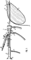
- FIG. 1 shows the instrument 1 according to the invention as it is used to open an encapsulated implant 2 within a female breast 3.
- the breast 3 is shown in section.
- the shaft 4 of the instrument is inserted through an incision in the area of the nipple.
- the capsule to be opened and surrounding the implant 2 is identified by 5.
- the basic structure of the instrument 1 corresponds to a hysteroscope.
- a flushing connection 7 and a suction connection 8 are provided, via which liquid can be guided to the distal end of the instrument and can also be discharged again.
- a central channel for introducing and fixing a viewing optics 9 is provided, the eyepiece 10 thereof and lighting connector 11 can be seen in Figure 1.
- two instrument channels 12 and 13 are led out obliquely at the proximal end 6 of the shaft, each of which can be shut off via a cock 14.
- a laser fiber 15 - this is a light guide for applying laser light - is introduced within the instrument channel 13, the distal end of which lies at the distal end of the shaft and is used for the actual severing.
- the structure within the tubular shaft 4 results in particular from the cross-sectional illustration in FIG. 3.
- the shaft 4 itself has an essentially oval cross-section, in which a tube 16 with a D-shaped cross section for receiving and fixing the viewing optics 9 is arranged.
- the D-shaped tube 16 is located on the side of the shaft 4 on which it runs out distally to a channel-shaped end part 17 and extends over more than half of the shaft cross section, as can be seen from FIG. 3.
- the instrument channel 12 for the laser fiber 15 is formed in the region of the shaft 4 by a tube 18 located therein, which has a circular cross section and is arranged on one side of a long semiaxis 19 of the oval shaft cross section, specifically on the flat side of the D-shaped tube 16
- the tube 18 ends on the distal side in the region of the trough-shaped end part 17, but can also end shortly before, in order to allow the end of the laser fiber a certain elastic deformation, in order thereby to protect the fiber from breaking.
- the instrument channel 12 is not formed separately within the shaft 4, but is delimited by the shaft 4 itself, the flat part of the D-shaped tube 16 and one side of the tube 18.
- a wedge-shaped guide 20 is arranged near the distal shaft end within the shaft 4, which ensures that an instrument inserted into this channel 12 is deflected by the laser fiber 15 when it emerges from the distal shaft end. These Guide 20 is therefore provided in order to avoid a collision between laser fibers and thus possible damage to the laser fibers by this instrument.
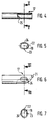
- the formation of the distal end of the shaft 4 as such can be seen in FIGS. 4 to 7.
- the trough-shaped end part 17 projecting beyond the tubular full cross-section is beveled at the front at its distal front end 21, as shown in FIG. 6, in order, for example, to make it easier to guide the instrument between capsule 6 and implant 2.
- the trough-shaped end part 17 is asymmetrical in its cross-sectional profile with respect to the long axis 22 of the shaft cross section.
- the channel profile includes the long semi-axis 19, extends to one side of this semi-axis 17 up to the short axis 23 of the shaft cross-section, while on the other side it clearly projects beyond a wall such that the channel profile as a whole extends over a circumferential angle of approximately 200 ° of the rest Shaft cross section extends. Depending on the requirements, the channel profile can also extend over a larger circumferential angle.
- This channel-shaped end part 17 protects in particular the implant from inadvertent collision with and thus against damage from the distal end of the laser fiber 15 and also from the distal end of the viewing optics 9.
- An additional viewing window 24 is therefore provided in the trough-shaped end part 17 of the shaft 4.
- This window 24 is formed by an approximately oval recess in the shaft wall in plan view, as can be seen from FIG. 6.
- the long axis of this Ovals lies in the axial direction of the instrument.
- the window 24 is provided in the flat side of the channel-shaped end part 17 which projects beyond the short axis 23, but it can also be provided in the bottom of the channel profile, if appropriate.
- the embodiment described above has proven to be particularly advantageous for opening the encapsulation, that is to say for severing the encapsulation, since the implant 2 with respect to the capsule 5 is protected with the side viewing window 24 with the safe protection of the shaft 4, in particular the channel-shaped end part 17 can be observed during processing. As usual, the processing point itself is controlled by the viewing optics 9.
- an additional bevel 25 is provided in the region of the distal end of the shaft, specifically on the end face opposite the channel-shaped end part 17, where the shaft 4 merges into the channel-shaped part 17 .
- This bevel 25 of the end face is shown in Figure 4.
Abstract
Description
Die Erfindung betrifft ein endoskopisches Instrument mit den im Oberbegriff des Anspruchs 1 angegebenen Merkmalen.The invention relates to an endoscopic instrument with the features specified in the preamble of claim 1.
Die vorliegende Erfindung geht aus von einem Pan-Hysteroskop-System, wie es beispielhaft von der Richard Wolf GmbH in Knittlingen angeboten und vertrieben wird. Bei diesem Instrument liegen nebeneinander angeordnet innerhalb des Schaftes eine Betrachtungsoptik sowie ein Behandlungsinstrument. Da das distale Schaftende in einen rinnenförmigen Teil ausläuft, liegen sowohl Optik als auch Instrument zu einer Seite geschützt während sie zur anderen, also zu der offenen Seite des rinnenförmigen Teils derart offen liegen, daß beispielsweise das Instrument in diese Richtung abgebogen oder auch in seiner Axialrichtung verschoben werden kann. Als Instrument kann beispielsweise eine flexible Zange, eine Laserfaser oder dergleichen eingesetzt werden. Ein solches Instrument ist insbesondere zur endoskopischen Untersuchung und Behandlung der Gebährmutter vorgesehen.The present invention is based on a pan-hysteroscope system, as is offered and sold by Richard Wolf GmbH in Knittlingen, for example. In this instrument, viewing optics and a treatment instrument are arranged side by side within the shaft. Since the distal shaft end ends in a channel-shaped part, both the optics and the instrument are protected on one side while they are open on the other, that is to say on the open side of the channel-shaped part, in such a way that, for example, the instrument is bent in this direction or in its axial direction can be moved. For example, flexible pliers, laser fibers or the like can be used as the instrument. Such an instrument is particularly intended for endoscopic examination and treatment of the uterus.
Insbesondere zur Brustrekonstruktion werden seit langer Zeit Silikoneinlagen verwendet. Bei solchen Silikoneinlagen kommt es gelegentlich zur Verkapselung des Implantates. Auch sind Beschädigungen des Implantates nicht auszuschließen. In solchen Fällen war es bisher üblich, auf chirurgischem Wege das Implantat zu überprüfen, die Verkapselung aufzulösen oder ggf. das Implantat auszutauschen. Hiervon ausgehend liegt der vorliegenden Erfindung die Aufgabe zugrunde, ein endoskopisches Instrument so auszubilden, daß sowohl die visuelle Prüfung des Implantates als auch die Lösung einer Verkapselung sowie ggf. weitere Eingriffe insbesondere im Bereich der weiblichen Brust mit genügender Sicherheit endoskopisch und damit minimal invasiv durchgeführt werden können.Silicone inlays have been used for a long time, particularly for breast reconstruction. With such silicone inserts, the implant is sometimes encapsulated. Damage to the implant cannot be ruled out. In such cases it has been so far It is usual to check the implant by surgery, to dissolve the encapsulation or, if necessary, to replace the implant. Proceeding from this, the present invention is based on the object of designing an endoscopic instrument in such a way that both the visual inspection of the implant and the release of an encapsulation and, if appropriate, further interventions, in particular in the area of the female breast, are carried out with sufficient security endoscopically and thus minimally invasively can.
Gemäß der Erfindung wird dies ausgehend von dem einleitend genannten Stand der Technik (Hysteroskop) dadurch erreicht, daß in dem distalen rinnenförmig auslaufenden Endteil des Schaftes eine Ausnehmung zur Bildung eines zusätzlichen Ausblickfensters für die Betrachtungsoptik vorgesehen ist.According to the invention, this is achieved on the basis of the prior art mentioned above (hysteroscope) in that a recess is provided in the distal, tapered end part of the shaft for forming an additional viewing window for the viewing optics.
Das erfindungsgemäße Instrument ermöglicht endoskopische Eingriffe im Bereich der weiblichen Brust, insbesondere im Zusammenhang mit der Inspektion und Lösung einer Verkapselung des Implantates. Natürlich können mit einem solchen Instrument auch andere Eingriffe, wie beispielsweise Gewebeentnahmen oder zu anderen diagnostischen Zwecken erfolgen. Der Operateur führt das erfindungsgemässe Instrument im Bereich der Brustwarze ein und kann dann ohne offene Operation zunächst einmal das Implantat inspizieren und ggf. auch eine Verkapselung eröffnen. Bei allen derartigen endoskopischen Eingriffen ist der Schutz des Implantates besonders zu beachten. Hierfür ist u.a. der rinnenförmige Endteil des Schaftes vorgesehen, der sowohl die Betrachtungsoptik als auch das Behandlungsinstrument, beispielsweise eine Laserfaser, zu einer Seite hin abschirmt. Denn es ist in jedem Falle ein Kontakt zwischen der Laserfaser einerseits und dem Implantat andererseits zu vermeiden. Um dies sicher zu vermeiden, genügt aber die schnabelförmige Ausbildung des distalen Schaftendes allein nicht, denn es ist insbesondere bei der Eröffnung der Verkapselung erforderlich, stets das Implantat im Blick zu haben. Um aber einerseits den erforderlichen Schutz zum Implantat zu gewähren andererseits aber gleichzeitig eine visuelle Kontrolle des Implantates, zumindest eines Teiles davon, durchführen zu können, ist das zusätzliche Ausblickfenster in dem rinnenförmig auslaufenden Endteil des Schaftendes vorgesehen. Der Operateur kann also während des Eröffnens der Verkapselung stets das Implantat beobachten. Die rinnenförmige Ausbildung des Schaftendes gewährleistet bei bestimmungsgemäßer Handhabung zudem, daß das Behandlungsinstrument stets nur in seiner axialen Richtung bzw. in der vom Implantat abgewandten Richtung, also zur offenen Seite des Rinnenprofils hin bewegt und eingesetzt werden kann und daß andererseits das Instrument selbst auf dem Implantat entlanggleitet.The instrument according to the invention enables endoscopic interventions in the area of the female breast, in particular in connection with the inspection and release of an encapsulation of the implant. Of course, such an instrument can also be used for other interventions, such as tissue extraction or for other diagnostic purposes. The surgeon inserts the instrument according to the invention in the area of the nipple and can then first of all inspect the implant without an open operation and, if necessary, also open an encapsulation. The protection of the implant must be given special attention for all such endoscopic interventions. For this purpose, the channel-shaped end part of the shaft is provided, which shields both the viewing optics and the treatment instrument, for example a laser fiber, to one side. In any case, contact between the laser fiber on the one hand and the implant on the other must be avoided. In order to avoid this safely, the beak-shaped design of the distal shaft end alone is not sufficient, because it is particularly the case with the Opening of the encapsulation is necessary to always keep an eye on the implant. However, in order to provide the necessary protection for the implant on the one hand and at the same time to be able to carry out a visual inspection of the implant, at least part of it, the additional viewing window is provided in the channel-shaped end part of the shaft end. The operator can thus always observe the implant while the encapsulation is being opened. The trough-shaped design of the shaft end also ensures that the treatment instrument can only be moved and used in its axial direction or in the direction facing away from the implant, i.e. towards the open side of the channel profile, and that the instrument itself can be used on the implant slides along.
Gemäß der Erfindung wird bevorzugt eine Laserfaser als Behandlungsinstrument eingesetzt, es kann jedoch auch eine HF-Sonde oder ein mechanisches Instrument, beispielsweise eine Zange oder ein Kombinationsinstrument eingesetzt werden. Insbesondere für die vorerwähnte Eröffnung der Kapsel hat sich der Einsatz einer Laserfaser bewährt, die beispielsweise mittels eines Neodym-YAG-Laser gespeist wird. Es versteht sich, daß mit dem erfindungsgemäßen Instrument auch Gewebeentnahmen oder andere Eingriffe vorgenommen werden können.According to the invention, a laser fiber is preferably used as the treatment instrument, but an HF probe or a mechanical instrument, for example a pair of pliers or a combination instrument, can also be used. The use of a laser fiber, which is fed, for example, by means of a neodymium-YAG laser, has proven particularly suitable for the aforementioned opening of the capsule. It is understood that tissue removal or other interventions can also be carried out with the instrument according to the invention.
Bevorzugt weist das Instrument einen im wesentlichen ovalen Querschnitt auf, wobei der rinnenförmige Endteil bezogen auf den übrigen Schaftquerschnitt so ausgebildet und angeordnet ist, daß er eine lange Halbachse des Querschnittovals einschließt. Die ovale Querschnittsform als solche bietet zunächst einmal im Vergleich zu einem runden Querschnitt gleichen Durchmessers den Vorteil eines geringeren Umfangs und damit einer geringeren Belastung der Eingriffsöffnung. In diesem Querschnittsoval können dann Betrachtungsoptik und Behandlungsinstrument so nebeneinander liegend angeordnet werden, daß die Betrachtungsoptik an dem Schaftteil unmittelbar anliegend ist, der zu dem rinnenförmigen Endteil ausläuft, so daß einerseits ein freier Blick durch das zusätzliche Ausblickfenster in diesem Endteil und andererseits ein freier Blick auf das Behandlungsinstrument und die davon behandelte Gewebestelle gewährleistet ist.The instrument preferably has an essentially oval cross section, the channel-shaped end part being designed and arranged with respect to the remaining shaft cross section such that it includes a long semi-axis of the cross section oval. The oval cross-sectional shape as such initially offers the advantage of a smaller circumference and thus a lower load on the engagement opening compared to a round cross-section of the same diameter. The viewing optics and treatment instrument can then be in this cross-sectional oval so that they are arranged side by side so that the viewing optics are in direct contact with the shaft part that runs out to the channel-shaped end part, so that on the one hand a clear view through the additional viewing window in this end part and on the other hand a clear view of the treatment instrument and the tissue site treated by it ensure is.
Es versteht sich, daß insbesondere das distale Instrumentenende soweit wie möglich gerundet ausgebildet ist, um ein möglichst reibungsloses und verletzungsfreies Gleiten innerhalb des Körpers zu ermöglichen. Bevorzugt ist jedoch der rinnenförmige Endteil des Schaftes zusätzlich mit einer Abschrägung an seiner distalen Stirnseite versehen, um auf diese Weise ein leichteres Vorschieben in Axialrichtung im Körperinneren zu ermöglichen, was durch die zugeführte Spülflüssigkeit noch unterstützt wird.It goes without saying that, in particular, the distal end of the instrument is rounded as far as possible in order to enable the smoothest possible and injury-free sliding within the body. However, the trough-shaped end part of the shaft is preferably additionally provided with a bevel on its distal end face, in order in this way to enable easier advancement in the axial direction inside the body, which is further supported by the irrigation liquid supplied.
Insbesondere bei der vorerwähnten Eröffnung einer Implantatverkapselung ist es von Vorteil, wenn sich der rinnenförmige Endteil des Schaftes nicht wie bei Hysteroskopen üblich nur um einen Umfangswinkel von etwa 180°, sondern darüber hinaus bis etwa 200° oder mehr erstreckt, da dann die distalen Enden von Betrachtungsoptik und Behandlungsinstrument noch besser geschützt liegen und somit eine Verletzung des Implantates weitestgehend ausgeschlossen werden kann. Dabei hat es sich besonders bewährt, wenn das Rinnenprofil des distalen Schaftendteils nicht symmetrisch ausgebildet ist, sondern eine Wandung zu einer Seite der langen Achse des Querschnittovals verlängert ist. Bevorzugt liegt dann die Ausnehmung zur Bildung des zusätzlichen Ausblickfensters in diesem Teil der Wandung. Mit einer solchen Anordnung kann während des Eröffnens der Kapsel durch das zusätzliche Ausblickfenster nicht nur das Implantat selbst, sondern auch die Lage des Implantats zur Verkapselung kontrolliert werden.Particularly when opening the implant encapsulation as mentioned above, it is advantageous if the groove-shaped end part of the shaft does not extend only by a circumferential angle of approximately 180 °, as is usual in hysteroscopes, but also extends to approximately 200 ° or more, since then the distal ends of Viewing optics and treatment instrument are even better protected and injury to the implant can be largely excluded. It has proven particularly useful if the channel profile of the distal shaft end part is not symmetrical, but rather a wall is extended to one side of the long axis of the cross-sectional oval. The recess for forming the additional viewing window is then preferably located in this part of the wall. With such an arrangement, not only the implant itself but also the position of the implant in relation to the encapsulation can be checked through the additional viewing window during the opening of the capsule.
Es hat sich als vorteilhaft erwiesen wenn die Ausnehmung in Draufsicht eine etwa ovale Kontur aufweist, da dann einerseits eine genügend große Öffnung realisiert werden und die Verletzungsgefahr gering gehalten werden kann. Zu einer weiteren Verringerung der Verletzungsgefahr dient auch die Abschrägung des stirnseitigen distalen Endes der Schaftwandung in dem dem rinnenförmigen Endteil gegenüberliegenden Bereich.It has proven to be advantageous if the recess has an approximately oval contour in plan view, since on the one hand a sufficiently large opening can be realized and the risk of injury can be kept low. The beveling of the distal end of the shaft wall in the region opposite the channel-shaped end part also serves to further reduce the risk of injury.
Um einerseits die Betrachtungsoptik zuverlässig innerhalb des Schaftes festzulegen und andererseits eine Berührung mit dem Behandlungsinstrument zu vermeiden, ist es vorteilhaft, innerhalb des Schaftes ein im Querschnitt etwa D-förmiges Rohr vorzusehen, in das die Betrachtungsoptik eingeführt und in dem diese dann festgelegt werden kann. Für das Behandlungsinstrument kann insbesondere dann, wenn es sich um eine Laserfaser handelt, ein weiteres Rohr zu Führung dieser Faser vorgesehen werden, das innerhalb des Schaftes an der Flachseite des im Querschnitt D-förmigen Rohres anliegt. Wenn dieses Rohr außermittig angeordnet wird, bleibt innerhalb des Schaftes noch Raum zum Einführen eines weiteren Instrumentes. Um eine Kollision zwischen einem solchen weiteren Instrument und der sehr empfindlichen Laserfaser im distalen Bereich zu vermeiden, ist innerhalb des distalen Schaftendes eine Führung für dieses weitere Instrument vorgesehen, und zwar in Form eines Keiles derart, daß dieses weitere Instrument beim Austritt aus dem Schaftende von der Laser-Lichtleitfaser weggerichtet abgelenkt wird.In order on the one hand to reliably fix the viewing optics within the shaft and on the other hand to avoid contact with the treatment instrument, it is advantageous to provide an approximately D-shaped tube inside the shaft into which the viewing optics can be inserted and in which it can then be fixed. For the treatment instrument, in particular if it is a laser fiber, a further tube for guiding this fiber can be provided, which rests within the shaft on the flat side of the tube with a D-shaped cross section. If this tube is arranged off-center, there is still space within the shaft for inserting another instrument. In order to avoid a collision between such an additional instrument and the very sensitive laser fiber in the distal region, a guide for this additional instrument is provided within the distal shaft end, in the form of a wedge such that this additional instrument exits from the shaft end of the laser optical fiber is deflected away.
Innerhalb des Schaftes können, sofern erforderlich, Saug-, Spül- oder andere Kanäle und/oder ggf. auch Rohre vorgesehen sein.If necessary, suction, rinsing or other channels and / or possibly also pipes can be provided within the shaft.
Die Erfindung ist nachfolgend anhand eines in der Zeichnung dargestellten Ausführungsbeispiels näher erläutert. Es zeigen:
- Figur 1
- in stark schematisierter Darstellung das erfindungsgemäße Instrument im operativen Einsatz,
- Figur 2
- eine Seitenansicht des Instrumentes nach Figur 1 mit im Längsschnitt dargestelltem Schaft,
- Figur 3
- einen Schnitt durch den Schaft des Instrumentes nach Figur 2 längs der Schnittlinie III-III,
- Figur 4
- in vergrößerter Darstellung den distalen Endbereich des Instrumentenschaftes in Draufsicht,
- Figur 5
- einen Schnitt längs der Schnittlinie V-V in Figur 4,
- Figur 6
- eine um 90° gedrehte Ansicht des Schaftteiles nach Figur 4 und
- Figur 7
- einen Schnitt längs der Schnittlinie VII-VII in Figur 6.
- Figure 1
- in a highly schematic representation the instrument according to the invention in operative use,
- Figure 2
- 2 shows a side view of the instrument according to FIG. 1 with the shaft shown in longitudinal section,
- Figure 3
- 3 shows a section through the shaft of the instrument according to FIG. 2 along the section line III-III,
- Figure 4
- in an enlarged view the distal end region of the instrument shaft in plan view,
- Figure 5
- 3 shows a section along the section line VV in FIG. 4,
- Figure 6
- a view rotated by 90 ° of the shaft part according to Figure 4 and
- Figure 7
- a section along the section line VII-VII in Figure 6.
In Figur 1 ist das erfindungsgemäße Instrument 1 so dargestellt, wie es zum Eröffnen eines verkapselten Implantates 2 innerhalb einer weiblichen Brust 3 eingesetzt wird. Die Brust 3 ist im Schnitt dargestellt. Das Instrument ist mit seinem Schaft 4 durch eine Inzision im Bereich der Brustwarze eingeführt. Die zu eröffnende, das Implantat 2 umgebende Kapsel ist mit 5 gekennzeichnet.1 shows the instrument 1 according to the invention as it is used to open an encapsulated implant 2 within a female breast 3. The breast 3 is shown in section. The shaft 4 of the instrument is inserted through an incision in the area of the nipple. The capsule to be opened and surrounding the implant 2 is identified by 5.
Das Instrument 1 als solches entspricht in seinem Grundaufbau einem Hysteroskop. Am proximalseitigen Schaftende 6 sind ein Spülanschluß 7 und ein Sauganschluß 8 vorgesehen, über die Flüssigkeit zum distalen Instrumentenende geführt und auch wieder abgeführt werden kann. Weiterhin ist ein zentraler Kanal zum Einführen und Festlegen einer Betrachtungsoptik 9 vorgesehen, deren Okular 10 sowie Beleuchtungsanschluß 11 in Figur 1 erkennbar ist. Weiterhin sind am proximalseitigen Schaftende 6 zwei Instrumentenkanäle 12 und 13 schräg herausgeführt, die jeweils über einen Hahn 14 absperrbar sind. Innerhalb des Instrumentenkanals 13 ist eine Laserfaser 15 - es handelt sich hierbei um einen Lichtleiter zum Applizieren von Laserlicht - eingeführt, dessen distales Ende am distalen Schaftende liegt und mit dem die eigentliche Durchtrennung erfolgt.The basic structure of the instrument 1 corresponds to a hysteroscope. At the proximal end 6 of the shaft, a flushing connection 7 and a suction connection 8 are provided, via which liquid can be guided to the distal end of the instrument and can also be discharged again. Furthermore, a central channel for introducing and fixing a viewing optics 9 is provided, the eyepiece 10 thereof and lighting connector 11 can be seen in Figure 1. Furthermore, two
Der Aufbau innerhalb des rohrförmigen Schaftes 4 ergibt sich insbesondere aus der Querschnittsdarstellung in Figur 3. Der Schaft 4 selbst weist einen im wesentlichen ovalen Querschnitt auf, in dem ein im Querschnitt D-förmiges Rohr 16 zur Aufnahme und Festlegung der Betrachtungsoptik 9 angeordnet ist. Das D-förmige Rohr 16 liegt zu der Seite des Schaftes 4, auf der dieser distalseitig zu einem rinnenförmigen Endteil 17 ausläuft und erstreckt sich über mehr als die Hälfte des Schaftquerschnitts, wie aus Figur 3 ersichtlich ist. Der Instrumentenkanal 12 für die Laserfaser 15 ist im Bereich des Schaftes 4 durch ein darin befindliches Rohr 18 gebildet, das kreisförmigen Querschnitt hat und zu einer Seite einer langen Halbachse 19 des ovalen Schaftquerschnitts angeordnet ist, und zwar an der Flachseite des D-förmigen Rohres 16. Das Rohr 18 endet distalseitig im Bereich des rinnenförmigen Endteils 17, kann jedoch auch kurz davor enden, um dem Ende der Laserfaser eine gewisse elastische Verformung zu ermöglichen, um dadurch die Faser vor einem Bruch zu schützen.The structure within the tubular shaft 4 results in particular from the cross-sectional illustration in FIG. 3. The shaft 4 itself has an essentially oval cross-section, in which a
Der Instrumentenkanal 12 ist innerhalb des Schaftes 4 nicht gesondert ausgebildet, sondern wird durch den Schaft 4 selbst, dem flachen Teil des D-förmigen Rohres 16 sowie eine Seite des Rohres 18 begrenzt. Nahe dem distalen Schaftende ist innerhalb des Schaftes 4 eine keilförmige Führung 20 angeordnet, die dafür sorgt, daß ein in diesen Kanal 12 eingeführtes Instrument beim Austritt aus dem distalen Schaftende von der Laserfaser 15 abweisend gelenkt wird. Diese Führung 20 ist also vorgesehen, um eine Kollision zwischen Laserfaser und damit eine mögliche Beschädigung der Laserfaser durch dieses Instrument zu vermeiden.The
Die Ausbildung des distalen Endes des Schaftes 4 als solches ist den Figuren 4 bis 7 zu entnehmen. Der über den rohrförmigen Vollquerschnitt hinausragende rinnenförmige Endteil 17 ist an seinem distalen vorderen Ende 21 stirnseitig abgeschrägt ausgebildet, wie dies anhand von Figur 6 dargestellt ist, um beispielsweise das Entlangführen des Instrumentes zwischen Kapsel 6 und Implantat 2 zu erleichtern. Wie sich aus den Schnittdarstellungen nach den Figuren 5 und 7 ergibt, ist der rinnenförmige Endteil 17 in seinem Querschnittsprofil bezogen auf die lange Achse 22 des Schaftquerschnittes asymetrisch ausgebildet. Das Rinnenprofil schließt die lange Halbachse 19 ein, reicht zu einer Seite dieser Halbachse 17 bis zur kurzen Achse 23 des Schaftquerschnitts während es zur anderen Seite mit einer Wandung diese deutlich überragt derart, daß sich das Rinnenprofil insgesamt über einen Umfangswinkel von etwa 200° des übrigen Schaftquerschnitts erstreckt. Je nach Anforderungen kann sich das Rinnenprofil auch über einen größeren Umfangswinkel erstrecken.The formation of the distal end of the shaft 4 as such can be seen in FIGS. 4 to 7. The trough-shaped
Dieser rinnenförmige Endteil 17 schützt insbesondere das Implantat vor unbeabsichtigter Kollision mit und somit vor Beschädigung durch das distale Ende der Laserfaser 15 sowie auch durch das distale Ende der Betrachtungsoptik 9.This channel-shaped
Dieser Schutz allein reicht jedoch nicht aus, um beispielsweise die das Implantat 2 umgebende Kapsel 5 sicher zu lösen. Es ist deshalb ein zusätzliches Ausblickfenster 24 in dem rinnenförmigen Endteil 17 des Schaftes 4 vorgesehen. Dieses Fenster 24 ist durch eine in Draufsicht etwa ovale Ausnehmung in der Schaftwandung gebildet, wie dies anhand von Figur 6 ersichtlich ist. Die lange Achse dieses Ovals liegt in Achsrichtung des Instrumentes. Das Fenster 24 ist wie aus den Figuren ersichtlich in der die kurze Achse 23 überragenden Flachseite des rinnenförmigen Endteils 17 vorgesehen, es kann jedoch ggf. auch im Boden des Rinnenprofils vorgesehen sein. Die vorstehend beschriebene Ausführungsform hat sich jedoch insbesondere zum Eröffnen der Verkapselung, also zum Durchtrennen der Verkapselung als günstig erwiesen, da mit dem seitlichen Ausblickfenster 24 unter dem sicheren Schutz des Schaftes 4, insbesondere des rinnenförmigen Endteils 17 das Implantat 2 in bezug auf die Kapsel 5 während der Bearbeitung beobachtet werden kann. Die Bearbeitungsstelle an sich wird wie üblich durch die Betrachtungsoptik 9 kontrolliert.However, this protection alone is not sufficient to safely detach the capsule 5 surrounding the implant 2, for example. An
Um das Verletzungsrisiko beim axialen Vorschieben des Schaftes 4 innerhalb des Körpers weiter zu vermindern, ist eine zusätzliche Abschrägung 25 im Bereich des distalen Schaftendes vorgesehen, und zwar an der dem rinnenförmigen Endteil 17 gegenüberliegenden Stirnseite, dort wo der Schaft 4 in den rinnenförmigen Teil 17 übergeht. Diese Abschrägung 25 der Stirnseite ist in Figur 4 dargestellt.In order to further reduce the risk of injury when the shaft 4 is advanced axially within the body, an
- 11
- - Instrument- instrument
- 22nd
- - Implantat- implant
- 33rd
- - Brust- Chest
- 44th
- - Schaft- shaft
- 55
- - Kapsel- capsule
- 66
- - proximalseitiges Schaftende- proximal shaft end
- 77
- - Spülanschluß- flushing connection
- 88th
- - Sauganschluß- suction connection
- 99
- - Betrachtungsoptik- viewing optics
- 1010th
- - Okular- eyepiece
- 1111
- - Beleuchtungsanschluß- lighting connection
- 1212th
- - Instrumentenkanal- Instrument channel
- 1313
- - Instrumentenkanal- Instrument channel
- 1414
- - Hahn- rooster
- 1515
- - Laserfaser- laser fiber
- 1616
- - D-förmiges Rohr- D-shaped tube
- 1717th
- - rinnenförmiger Endteil- gutter-shaped end part
- 1818th
- - Rohr- Pipe
- 1919th
- - lange Halbachse- long semi-axis
- 2020th
- - keilförmige Führung- wedge-shaped guide
- 2121
- - vorderes Ende von 17- front end of 17
- 2222
- - lange Achse- long axis
- 2323
- - kurze Achse- short axis
- 2424th
- - Fenster- Window
- 2525th
- - Abschrägung- bevel
Claims (10)
Applications Claiming Priority (2)
| Application Number | Priority Date | Filing Date | Title |
|---|---|---|---|
| DE4241643 | 1992-12-02 | ||
| DE4241643 | 1992-12-02 |
Publications (2)
| Publication Number | Publication Date |
|---|---|
| EP0601427A2 true EP0601427A2 (en) | 1994-06-15 |
| EP0601427A3 EP0601427A3 (en) | 1997-08-20 |
Family
ID=6474911
Family Applications (1)
| Application Number | Title | Priority Date | Filing Date |
|---|---|---|---|
| EP93119171A Withdrawn EP0601427A3 (en) | 1992-12-02 | 1993-11-29 | Endoscopic instrument. |
Country Status (3)
| Country | Link |
|---|---|
| US (1) | US5421323A (en) |
| EP (1) | EP0601427A3 (en) |
| CA (1) | CA2110469A1 (en) |
Families Citing this family (22)
| Publication number | Priority date | Publication date | Assignee | Title |
|---|---|---|---|---|
| US5797960A (en) | 1993-02-22 | 1998-08-25 | Stevens; John H. | Method and apparatus for thoracoscopic intracardiac procedures |
| US6346074B1 (en) | 1993-02-22 | 2002-02-12 | Heartport, Inc. | Devices for less invasive intracardiac interventions |
| WO1996001589A1 (en) * | 1994-07-07 | 1996-01-25 | Ueth & Haug Gmbh | Endoscope |
| GB2306329B (en) * | 1995-10-16 | 2000-04-19 | Precision Optics Corp | Medical visualisation device |
| US5951497A (en) * | 1996-09-03 | 1999-09-14 | Clinical Innovation Associates, Inc. | Pressure catheter device with enhanced positioning features |
| US6629630B2 (en) * | 1998-06-19 | 2003-10-07 | Scimed Life Systems, Inc. | Non-circular resection device and endoscope |
| US20080045934A1 (en) * | 2000-10-24 | 2008-02-21 | Galil Medical Ltd. | Device and method for coordinated insertion of a plurality of cryoprobes |
| US20020068929A1 (en) * | 2000-10-24 | 2002-06-06 | Roni Zvuloni | Apparatus and method for compressing a gas, and cryosurgery system and method utilizing same |
| US6706037B2 (en) * | 2000-10-24 | 2004-03-16 | Galil Medical Ltd. | Multiple cryoprobe apparatus and method |
| US20030130649A1 (en) * | 2000-12-15 | 2003-07-10 | Murray Steven C. | Method and system for treatment of benign prostatic hypertrophy (BPH) |
| US6986764B2 (en) * | 2000-12-15 | 2006-01-17 | Laserscope | Method and system for photoselective vaporization of the prostate, and other tissue |
| JP2002338688A (en) * | 2001-05-15 | 2002-11-27 | Sumitomo Chem Co Ltd | Method for producing purified polyethersulfone |
| US20080051776A1 (en) * | 2001-05-21 | 2008-02-28 | Galil Medical Ltd. | Thin uninsulated cryoprobe and insulating probe introducer |
| US20080051774A1 (en) * | 2001-05-21 | 2008-02-28 | Galil Medical Ltd. | Device and method for coordinated insertion of a plurality of cryoprobes |
| JP4768154B2 (en) * | 2001-06-29 | 2011-09-07 | テルモ株式会社 | Medical energy irradiation device |
| AU2003222234A1 (en) * | 2002-02-22 | 2003-09-09 | Laserscope | Method and system for photoselective vaporization for gynecological treatments |
| US8007847B2 (en) * | 2004-01-13 | 2011-08-30 | Eytan Biderman | Feeding formula appliance |
| EP1973461A2 (en) * | 2005-12-16 | 2008-10-01 | Galil Medical Ltd | Apparatus and method for thermal ablation of uterine fibroids |
| JP2009524469A (en) * | 2006-01-26 | 2009-07-02 | ガリル メディカル リミテッド | Apparatus and method for coordinated insertion of multiple cryoprobes |
| US20080287940A1 (en) * | 2007-05-14 | 2008-11-20 | Hunter Lowell D | Fiber Pole Tip |
| US8419718B2 (en) * | 2007-05-15 | 2013-04-16 | Ams Research Corporation | Laser handle and fiber guard |
| DE102009015392A1 (en) * | 2009-03-20 | 2010-09-23 | Karl Storz Gmbh & Co. Kg | Medical instrument, in particular hysteroscope |
Citations (6)
| Publication number | Priority date | Publication date | Assignee | Title |
|---|---|---|---|---|
| US3299883A (en) * | 1963-11-08 | 1967-01-24 | Engelhard Hanovia Inc | Gynecologic instrument |
| DE2327920A1 (en) * | 1973-06-01 | 1974-12-19 | Olympus Optical Co | ENDOSCOPE |
| DE3441029A1 (en) * | 1983-11-11 | 1985-05-23 | Fuji Photo Optical Co., Ltd., Omiya, Saitama | ENDOSCOPE |
| DE3637789A1 (en) * | 1985-11-13 | 1987-05-21 | Olympus Optical Co | ENDOSCOPE |
| DE3716401A1 (en) * | 1986-05-15 | 1987-11-19 | Olympus Optical Co | ADAPTER FOR AN ENDOSCOPE HEAD |
| US4867138A (en) * | 1987-05-13 | 1989-09-19 | Olympus Optical Co., Ltd. | Rigid electronic endoscope |
Family Cites Families (12)
| Publication number | Priority date | Publication date | Assignee | Title |
|---|---|---|---|---|
| US879224A (en) * | 1906-08-28 | 1908-02-18 | Reinhold H Wappler | Cystoscope. |
| US2018335A (en) * | 1933-08-16 | 1935-10-22 | Wappler Frederick Charles | Endoscopic instrument |
| US2112056A (en) * | 1934-09-19 | 1938-03-22 | Wappler Frederick Charles | Blunted endoscopic instrument |
| DE702374C (en) * | 1939-04-13 | 1941-02-06 | Georg Wolf G M B H | Body cavity examination device |
| US2487498A (en) * | 1946-05-31 | 1949-11-08 | American Cystoscope Makers Inc | Cystoscope |
| FR1166019A (en) * | 1956-06-28 | 1958-11-03 | Camera for photographing the interior of human body cavities | |
| US3850175A (en) * | 1972-07-03 | 1974-11-26 | J Lglesias | Resectoscope with continuous irrigation |
| DK131541B (en) * | 1973-09-03 | 1975-08-04 | Akad Tekn Videnskaber | Prostate rectoscope. |
| DE2601802C3 (en) * | 1976-01-20 | 1979-02-08 | Richard Wolf Gmbh, 7134 Knittlingen | Instruments for the treatment of urethral strictures |
| SU1214084A1 (en) * | 1983-07-22 | 1986-02-28 | Специальное Конструкторско-Технологическое Бюро Средств Неразрушающего Контроля | Endoscope |
| JPS61259637A (en) * | 1985-05-15 | 1986-11-17 | オリンパス光学工業株式会社 | Endoscope apparatus |
| US4905670A (en) * | 1988-12-28 | 1990-03-06 | Adair Edwin Lloyd | Apparatus for cervical videoscopy |
-
1993
- 1993-11-24 US US08/157,781 patent/US5421323A/en not_active Expired - Fee Related
- 1993-11-29 EP EP93119171A patent/EP0601427A3/en not_active Withdrawn
- 1993-12-01 CA CA002110469A patent/CA2110469A1/en not_active Abandoned
Patent Citations (6)
| Publication number | Priority date | Publication date | Assignee | Title |
|---|---|---|---|---|
| US3299883A (en) * | 1963-11-08 | 1967-01-24 | Engelhard Hanovia Inc | Gynecologic instrument |
| DE2327920A1 (en) * | 1973-06-01 | 1974-12-19 | Olympus Optical Co | ENDOSCOPE |
| DE3441029A1 (en) * | 1983-11-11 | 1985-05-23 | Fuji Photo Optical Co., Ltd., Omiya, Saitama | ENDOSCOPE |
| DE3637789A1 (en) * | 1985-11-13 | 1987-05-21 | Olympus Optical Co | ENDOSCOPE |
| DE3716401A1 (en) * | 1986-05-15 | 1987-11-19 | Olympus Optical Co | ADAPTER FOR AN ENDOSCOPE HEAD |
| US4867138A (en) * | 1987-05-13 | 1989-09-19 | Olympus Optical Co., Ltd. | Rigid electronic endoscope |
Non-Patent Citations (1)
| Title |
|---|
| SPIE MILESTONE SERIES : SELECTED PAPERS ON OPTICAL FIBERS IN MEDICINE, Bd. ms11, 1.Januar 1990, WASHINGTON (US), Seiten 73-94, XP000467434 I. KAWAHARA ET AL.: "FIBEROPTIC INSTRUMENT TECHNOLOGY" * |
Also Published As
| Publication number | Publication date |
|---|---|
| CA2110469A1 (en) | 1994-06-03 |
| US5421323A (en) | 1995-06-06 |
| EP0601427A3 (en) | 1997-08-20 |
Similar Documents
| Publication | Publication Date | Title |
|---|---|---|
| EP0601427A2 (en) | Endoscopic instrument | |
| DE19827360C2 (en) | Medical instrument for endoscopic removal of the saphenous vein | |
| DE19962209B4 (en) | Tip for an ultrasound endoscope | |
| DE19827468B4 (en) | Ligation device for an endoscope | |
| EP1610695B1 (en) | Surgical instrument system | |
| DE19631677C1 (en) | Endoscopic device for perforating veins | |
| DE3025785A1 (en) | DILATATOR | |
| DE3603344A1 (en) | DEVICE FOR CRUSHING STONES, ESPECIALLY KIDNEY AND GALLET STONES OR THE LIKE | |
| EP2229871B1 (en) | Medical instrument, in particular hysteroscope | |
| DE102010028167A1 (en) | Invasive instrument for processing vessels and a procedure | |
| DE3917663C2 (en) | ||
| DE3936811A1 (en) | Endoscope for removal of gall stones - has dilator formed from several telescopic tubes | |
| DE3644728C1 (en) | Salpingoscope | |
| DE10333956B4 (en) | Sichtobturator | |
| EP2029041A1 (en) | Handpiece intended particularly for medical laser applications | |
| EP3701890A1 (en) | An ophthalmological hand-held device and a set comprising an ophthalmological hand-held device | |
| EP4278947A1 (en) | Reusable rinse shaft for endoscope | |
| EP2265232B1 (en) | Surgical aid for ophthalmology | |
| DE2835812A1 (en) | Trocar instrument for insufflation of body cavities - includes endoscope stem and conical sleeve integral with distal end | |
| DE4340584A1 (en) | Endoscopic instrument for breast implant | |
| DE202017101684U1 (en) | Adapter for performing a percutaneous nephrolithotomy | |
| CH691758A5 (en) | Instrument for eye surgery; has cannula with flattened cross-section at least in part of cannula tube that is to be inserted into eye, with diameter of one axis smaller than second perpendicular axis | |
| DE102022105184A1 (en) | Obturator for a surgical instrument | |
| DE102019129811A1 (en) | Surgical instrument and optical obturator for a surgical instrument | |
| DE102010032151B4 (en) | Medical hand instrument for incising an incision in the sclera of the eye and trocar system |
Legal Events
| Date | Code | Title | Description |
|---|---|---|---|
| PUAI | Public reference made under article 153(3) epc to a published international application that has entered the european phase |
Free format text: ORIGINAL CODE: 0009012 |
|
| AK | Designated contracting states |
Kind code of ref document: A2 Designated state(s): AT DE FR GB |
|
| RIN1 | Information on inventor provided before grant (corrected) |
Inventor name: BOEBEL, MANFRED Inventor name: HERRMANN, UWE, DR. MED. DR. PHIL. |
|
| PUAL | Search report despatched |
Free format text: ORIGINAL CODE: 0009013 |
|
| AK | Designated contracting states |
Kind code of ref document: A3 Designated state(s): AT DE FR GB |
|
| STAA | Information on the status of an ep patent application or granted ep patent |
Free format text: STATUS: THE APPLICATION IS DEEMED TO BE WITHDRAWN |
|
| 18D | Application deemed to be withdrawn |
Effective date: 19980221 |