EP0602580A1 - Method and apparatus for manufacturing paper cushioning members - Google Patents
Method and apparatus for manufacturing paper cushioning members Download PDFInfo
- Publication number
- EP0602580A1 EP0602580A1 EP93120077A EP93120077A EP0602580A1 EP 0602580 A1 EP0602580 A1 EP 0602580A1 EP 93120077 A EP93120077 A EP 93120077A EP 93120077 A EP93120077 A EP 93120077A EP 0602580 A1 EP0602580 A1 EP 0602580A1
- Authority
- EP
- European Patent Office
- Prior art keywords
- projections
- paper
- recesses
- circumferential
- link
- Prior art date
- Legal status (The legal status is an assumption and is not a legal conclusion. Google has not performed a legal analysis and makes no representation as to the accuracy of the status listed.)
- Withdrawn
Links
Images


Classifications
-
- B—PERFORMING OPERATIONS; TRANSPORTING
- B31—MAKING ARTICLES OF PAPER, CARDBOARD OR MATERIAL WORKED IN A MANNER ANALOGOUS TO PAPER; WORKING PAPER, CARDBOARD OR MATERIAL WORKED IN A MANNER ANALOGOUS TO PAPER
- B31D—MAKING ARTICLES OF PAPER, CARDBOARD OR MATERIAL WORKED IN A MANNER ANALOGOUS TO PAPER, NOT PROVIDED FOR IN SUBCLASSES B31B OR B31C
- B31D5/00—Multiple-step processes for making three-dimensional articles ; Making three-dimensional articles
- B31D5/0039—Multiple-step processes for making three-dimensional articles ; Making three-dimensional articles for making dunnage or cushion pads
- B31D5/0065—Multiple-step processes for making three-dimensional articles ; Making three-dimensional articles for making dunnage or cushion pads including slitting and expanding flat material
-
- B—PERFORMING OPERATIONS; TRANSPORTING
- B26—HAND CUTTING TOOLS; CUTTING; SEVERING
- B26D—CUTTING; DETAILS COMMON TO MACHINES FOR PERFORATING, PUNCHING, CUTTING-OUT, STAMPING-OUT OR SEVERING
- B26D1/00—Cutting through work characterised by the nature or movement of the cutting member or particular materials not otherwise provided for; Apparatus or machines therefor; Cutting members therefor
- B26D1/01—Cutting through work characterised by the nature or movement of the cutting member or particular materials not otherwise provided for; Apparatus or machines therefor; Cutting members therefor involving a cutting member which does not travel with the work
- B26D1/12—Cutting through work characterised by the nature or movement of the cutting member or particular materials not otherwise provided for; Apparatus or machines therefor; Cutting members therefor involving a cutting member which does not travel with the work having a cutting member moving about an axis
- B26D1/14—Cutting through work characterised by the nature or movement of the cutting member or particular materials not otherwise provided for; Apparatus or machines therefor; Cutting members therefor involving a cutting member which does not travel with the work having a cutting member moving about an axis with a circular cutting member, e.g. disc cutter
- B26D1/24—Cutting through work characterised by the nature or movement of the cutting member or particular materials not otherwise provided for; Apparatus or machines therefor; Cutting members therefor involving a cutting member which does not travel with the work having a cutting member moving about an axis with a circular cutting member, e.g. disc cutter coacting with another disc cutter
- B26D1/245—Cutting through work characterised by the nature or movement of the cutting member or particular materials not otherwise provided for; Apparatus or machines therefor; Cutting members therefor involving a cutting member which does not travel with the work having a cutting member moving about an axis with a circular cutting member, e.g. disc cutter coacting with another disc cutter for thin material, e.g. for sheets, strips or the like
-
- B—PERFORMING OPERATIONS; TRANSPORTING
- B26—HAND CUTTING TOOLS; CUTTING; SEVERING
- B26F—PERFORATING; PUNCHING; CUTTING-OUT; STAMPING-OUT; SEVERING BY MEANS OTHER THAN CUTTING
- B26F1/00—Perforating; Punching; Cutting-out; Stamping-out; Apparatus therefor
- B26F1/18—Perforating by slitting, i.e. forming cuts closed at their ends without removal of material
- B26F1/20—Perforating by slitting, i.e. forming cuts closed at their ends without removal of material with tools carried by a rotating drum or similar support
-
- B—PERFORMING OPERATIONS; TRANSPORTING
- B31—MAKING ARTICLES OF PAPER, CARDBOARD OR MATERIAL WORKED IN A MANNER ANALOGOUS TO PAPER; WORKING PAPER, CARDBOARD OR MATERIAL WORKED IN A MANNER ANALOGOUS TO PAPER
- B31D—MAKING ARTICLES OF PAPER, CARDBOARD OR MATERIAL WORKED IN A MANNER ANALOGOUS TO PAPER, NOT PROVIDED FOR IN SUBCLASSES B31B OR B31C
- B31D1/00—Multiple-step processes for making flat articles ; Making flat articles
- B31D1/0031—Multiple-step processes for making flat articles ; Making flat articles the articles being paper nettings, e.g. by slitting and expanding webs or sheets
-
- B—PERFORMING OPERATIONS; TRANSPORTING
- B31—MAKING ARTICLES OF PAPER, CARDBOARD OR MATERIAL WORKED IN A MANNER ANALOGOUS TO PAPER; WORKING PAPER, CARDBOARD OR MATERIAL WORKED IN A MANNER ANALOGOUS TO PAPER
- B31D—MAKING ARTICLES OF PAPER, CARDBOARD OR MATERIAL WORKED IN A MANNER ANALOGOUS TO PAPER, NOT PROVIDED FOR IN SUBCLASSES B31B OR B31C
- B31D2205/00—Multiple-step processes for making three-dimensional articles
- B31D2205/0005—Multiple-step processes for making three-dimensional articles for making dunnage or cushion pads
- B31D2205/0076—Multiple-step processes for making three-dimensional articles for making dunnage or cushion pads involving particular machinery details
- B31D2205/0082—General layout of the machinery or relative arrangement of its subunits
Definitions
- the present invention relates to a method and apparatus for manufacturing paper cushioning members, and more particularly, to a method and apparatus for cutting a single sheet or plural sheets of work paper to be processed, such as unused paper or unnecessary newspaper, used copying paper, paper printed by an OA (Office Automation) equipment or used corrugated cardboard, to plural rows of thin intermittently-cut bands, stretching the resultant sheet or sheets of work paper to form a net, and crumpling the net-like sheet or sheets into an air-containing ball which has an adequate softness to thereby ensure continuous mass-production of such paper balls and permit the use of the paper balls as cushions or packings for transporting objects.
- OA Office Automation
- Another known cushion is a strong kraft paper processed to have short cuts and link portions by press working and then stretched to yield a fine almost beehive-like net.
- the first type namely balls made of newspaper
- the second type are soft to serve as good cushions, they are independent piece by piece and are easy to scatter, resulting in a lower working efficiency.
- it is difficult to use the torn and crumpled pieces of paper directly they are normally placed in a paper bag or a poly bag when in use. If the bag is torn or broken, however, the crumpled pieces of paper undesirably come out of the bag through the torn section.
- a method of manufacturing paper cushioning members comprising the steps of forming circumferential recesses and projections each of a given width on and around a surface of each of a pair of elongated roller members and engaging the recesses and projections of one of the roller members with those of the other roller member respectively; forming link-portion forming recesses each in a part of a circumferential surface of each of the projections in a horizontal direction or at a predetermined angle to the horizontal direction; inserting a single sheet or plural sheets of work paper to be processed between the pair of roller members and alternately forming cuts and link portions along the circumferential recesses and projections on the sheet or sheets of work paper, by using circumferential edges of the circumferential recesses and projections of the roller members; and stretching the sheet or sheets of work paper after alternate formation of the cuts and link portions in a direction perpendicular to a cutting direction, thus forming a net.
- an apparatus for manufacturing paper cushioning members comprising a pair of elongated roller members having circumferential recesses and projections each of a given width thereon and therearound; cutting blades formed at peripheral edges of surfaces of the circumferential projections; and link-portion forming recesses formed each in a part of a circumferential surface of each of the projections in a horizontal direction or at a predetermined angle to the horizontal direction, whereby with the recesses and projections of one of the roller members engaged with those of the other roller member respectively, when a single sheet or plural sheets of work paper to he processed are inserted in the engaging portion between the roller members, cuts and link portions are alternately formed along the cutting blades by using circumferential edges of the circumferential recesses and projections of the roller members, and the sheet or sheets of work paper after alternate formation of the cuts and link portions in a direction perpendicular to a cutting direction, thus forming a net.
- the apparatus according to the second aspect of this invention may be designed in such a way that the link-portion forming recesses are formed, all facing in one direction, in the circumferential projections.
- the apparatus according to the second aspect of this invention may also be designed in such a way that the link-portion forming recesses are formed in facing surfaces of those of the circumferential projections which are adjacent to each other.
- the apparatus according to the second aspect of this invention may be designed in such a way that the link-portion forming recesses are formed entirely across the circumferential projections in a horizontal direction.
- the apparatus according to the second aspect of this invention may further be designed in such a way that the link-portion forming recesses are formed entirely across the circumferential projections, inclined at a predetermined angle to a horizontal direction.
- a container for paper cushioning members comprising a paper-retaining container body having an openable/closable cover; and a take-out port formed in a front or side of the container body and having such a size as to allow insertion of a hand, whereby processed net-like paper cushioning members obtained by forming cuts and link portions in each work paper to be processed are retainable in the container body with that side of the net-like paper cushioning members along a cutting direction facing perpendicular to the take-out port and a desired number of sheets of the net-like paper cushioning members can be pulled out through the take-out port, so that when each of the net-like paper cushioning members is pulled out, a net is formed.
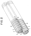
- reference numerals "1" and “2" denote a pair of elongated steel roller members whose shaft portions 11 and 21 at both ends supported on a frame F by means of bearings.
- Cutting blades 1' and 2' are formed at the peripheral edges of the circumferential surfaces R of circumferential projections formed on the roller members 1 and 2.
- Reference numerals "3" and “4" respectively denote rectangular, circumferential recesses and projections a given width (allowed to be about 5 mm), which are formed on each of the roller members 1 and 2.
- the circumferential recesses 3 of one roller member engage with the circumferential projections 4 of the other roller member, while the circumferential projections 4 of the former roller member engage with the circumferential recesses 3 of the latter roller member.
- Reference numeral "5" is a plate-shaped barrier provided on that side of the roller member pair 1 and 2 where work paper to be processed is to be discharged.
- the barrier 5 is disposed in a box-shaped container 10 in such a manner that its forward and backward movements are adjusted via a shaft 52 by a spring 51.
- Each projection 4 of each roller member has link-portion forming recesses 6 each formed in a part of its circumferential surface in the horizontal direction or at a predetermined angle ⁇ to the horizontal direction (about 1 to 10 degrees in Fig. 10).
- the length L of each projection 4 and the length G of each link-portion forming recess 6 can be set arbitrarily; in the example of Fig. 1, the length L is set to 50 mm while the length G is set to 7 mm. In this case, when the link-portion forming recess 6 of one, reference projection 3 of the lower roller member 1 comes to the top, the link-portion forming recesses 6 of the adjoining projections 3 come to the bottom.
- Fig. 1 illustrates the link-portion forming recesses 6 of the circumferential projections 4 of each roller member formed to all face in one direction.
- the link-portion forming recesses 6 shown in Fig. 7 are formed in the opposite surfaces of the adjacent circumferential projections 4.
- the link-portion forming recesses 6 in Fig. 9 are formed entirely across the circumferential projections 4 in the horizontal direction.
- the link-portion forming recesses 6 in Fig. 10 are formed in the circumferential projections, slightly inclined at a predetermined angle ⁇ (about 1 to 10 degrees in the illustrated example) to the horizontal direction.
- Reference numeral “7” denotes cuts formed in work paper P' at a given width W (5 mm in the illustrated examples) by the pair of roller members 1 and 2.
- Reference numerals “71,” “72,” “73,” ... “7 n” denote link portions which link the associated cuts 7 together.
- the cuts 7 and the link portions 71 to 7 n are set by the intermittent recesses of the circumferential recesses and projections 3 and 4 of the roller members 1 and 2 and the lengths between the intermittent recesses.
- Fig. 5 shows two thin bands linked by single link portions 71, ..., 7 n
- Fig. 13 shows three thin bands linked by two link portions 71 and 71, ..., 7 n and 7 n .
- reference numerals "8" and “9” are gears, which are attached to the shafts 11 and 21 of the roller members 1 and 2 and are engaged with each other to transmit power. Power from a motor (not shown) is transmitted to one of the gears, 8, through a belt or a chain.
- Alphabet "C” indicates a cutter provided on the work-paper supplying side of the roller members 1 and 2 to cut the work paper P', fed by those roller members 1 and 2, to a given length.
- Reference numeral “15” denotes a box-shaped container for retaining processed, net-like paper cushioning members.
- the container 15 has a take-out port 151 formed in the front to have such a size as to allow insertion of one hand, and retain many processed, net-like paper cushioning members with that side of the net-like paper cushioning members along the cutting length facing perpendicular to the take-out port 151.
- the cutting blades 1' and 2' of a given width are formed on the roller member pair 1 and 2, the link-portion forming recesses 6 are formed in the circumferential surface R of each projection 4 in the same direction, and the recesses 3 and projections 4 of one roller member are engaged with the projections 4 and recesses 3 of the other roller member respectively.
- a number of processed, net-like paper cushioning members P having those cuts and link portions are retained one on another in the container 15 through an openable/closable cover 152 at the top.
- the net-like paper cushioning members P are retained with the lengthwise direction of the cuts 7 set perpendicular to the take-out port 151.
- the cutting blades 1' and 2' of a given width are formed on the roller member pair 1 and 2, the link-portion forming recesses 6 are formed, facing each other, in the circumferential surfaces R of the adjoining projections 4, and the recesses 3 and projections 4 of one roller member are engaged with the projections 4 and recesses 3 of the other roller member respectively.
- a number of processed, net-like paper cushioning members P having those cuts and link portions formed in this manner are retained one on another in the container 15.
- a container 10 is provided on the discharging side of the roller members 1 and 2 as needed as shown in Fig. 12, the work paper P' is sent to the container 10, hitting against the barrier 5 in that container.
- the barrier 5 is shifted backward by a set amount by the spring in accordance with the discharging amount and is held there. Then, the work paper P' on the feeding side is cut by the cutter C at a given length L.
- a bottom plate 101 is opened around a hinge 102 to drop paper chunks P''.
- a poly bag should be set below the barrier 5, so that the discharged, crumpled paper members will be retained in the poly bag, contributing to preventing the products from being stained.
- the cutting blades 1' and 2' of a given width are formed on the roller member pair 1 and 2, the link-portion forming recesses 6 are formed across the circumferential surfaces R of the adjoining projections 4 in the horizontal direction.
- the cutting blades 1' and 2' of a given width are formed on the roller member pair 1 and 2, the link-portion forming recesses 6 are formed in the circumferential surfaces R of the adjoining projections 4, inclined at a predetermined angle ⁇ to the horizontal direction.
- a stack of sheets of ordinary work paper such as newspaper, used copying paper, or printed paper, can be processed together to provide a relatively large net.
- the processed, bundles of net-like paper cushioning members when in use may be retained one on another in the units of 10 kg per bundle, making the transpiration and storage of the paper cushioning members convenient. Further, the cuts are widened to form a net by simply pulling a desired number of paper cushioning members out from the take-out port at the front of the container. The resultant nets have only to be crumpled with hands to continuously mass-produce cushions or packings with adequate softness.
- the crumpled paper cushioning members When the net-like paper cushioning members intermittently cut by a pair of roller members are crumpled into paper chunks by the barrier, the crumpled paper cushioning members absorb a larger amount of air, so that the paper cushioning members become softer.
- a mechanism for cutting the processed paper cushioning member, already intermittently cut by a pair of roller members, to a predetermined length may be provided to always produce paper cushioning members with the same volume and constant quality.
- the link-portion forming recesses are formed, inclined at a predetermined angle with respect to the horizontal direction as shown in Fig. 14, the link-portion forming recesses obliquely come in contact with the recess surfaces of the associated link-portion forming recesses, preventing overstrain from being applied to the paper members.
- This design suppresses the wearing of the blades and is very advantageous.
Abstract
Disclosed are a method and apparatus for manufacturing paper cushioning members, which ensure continuous mass-production of paper balls, made by crumpling a sheet or sheets of work paper, and permit the use of the paper balls as cushions or packings for transporting objects. The method and apparatus are designed to form circumferential recesses (3) and projections (4) each of a given width on and around a surface of each of a pair of elongated roller members (1, 2) and engaging the recesses (3) and projections (4) of one of the roller members (1, 2) with the projections (4) and recess (3) of the other roller member respectively; form link-portion forming recesses (6) each in a part of a circumferential surface of each of the projections (4) in a horizontal direction or at a predetermined angle (ϑ) to the horizontal direction; insert a single sheet or plural sheets of work paper (P') to be processed between the pair of roller members (1, 2) and alternately forming cuts (7) and link portions (7₁, ..., 7n) along the circumferential recesses (3) and projections (4) on the sheet or sheets of work paper (P'), by using circumferential edges of the circumferential recesses (3) and projections (4) of the roller members (1, 2); and stretch the sheet or sheets of work paper (P) after alternate formation of the cuts (7) and link portions (7₁, ..., 7n) in a direction perpendicular to a cutting direction, thus forming a net (7').
Description
- The present invention relates to a method and apparatus for manufacturing paper cushioning members, and more particularly, to a method and apparatus for cutting a single sheet or plural sheets of work paper to be processed, such as unused paper or unnecessary newspaper, used copying paper, paper printed by an OA (Office Automation) equipment or used corrugated cardboard, to plural rows of thin intermittently-cut bands, stretching the resultant sheet or sheets of work paper to form a net, and crumpling the net-like sheet or sheets into an air-containing ball which has an adequate softness to thereby ensure continuous mass-production of such paper balls and permit the use of the paper balls as cushions or packings for transporting objects.
- There are cushions made of synthetic resin, which are to be placed between transporting objects and a box to protect the transporting objects against any damage. To avoid any pollution problem, however, there are paper cushions used for the same purpose instead of the synthetic-resin cushions. The simplest type of the paper cushions is a sheet of newspaper crumpled into a ball or paper torn to pieces which are then crumpled, or a corrugated cardboard cut into pieces as an intervening material depending on the usage.
- Another known cushion is a strong kraft paper processed to have short cuts and link portions by press working and then stretched to yield a fine almost beehive-like net.
- Of those paper cushions, the first type, namely balls made of newspaper, involve a troublesome work and are likely to vary in quality. Although the torn and crumpled pieces of paper, the second type, are soft to serve as good cushions, they are independent piece by piece and are easy to scatter, resulting in a lower working efficiency. In addition, since it is difficult to use the torn and crumpled pieces of paper directly, they are normally placed in a paper bag or a poly bag when in use. If the bag is torn or broken, however, the crumpled pieces of paper undesirably come out of the bag through the torn section.
- Although a corrugated cardboard, when cut to pieces, ensure an even thickness, those pieces are still hard and are not so suitable as cushions.
- With regard to the pressed kraft paper or the last type of cushion, when the processed kraft paper is stretched, a fine beehive-like net is formed due to the cuts and link portions. When the net is crumpled, soft and spongy feeling to some degree would be attained. Due to the press working, however, the processing size of a single sheet of kraft paper is limited and it is not possible to simultaneously process plural sheets of kraft paper. Further, as the resultant net is finely formed, the horizontal stretching ratio is small, so that the net, when crumpled into a ball, contain less air. Furthermore, as the link portions are short, the link portions are easily cut when stretched unless the kraft paper is very strong. In addition, as the net is finely formed, the material should be a thin sheet of paper and the net should be formed sheet by sheet.
- It is therefore an object of the present invention to provide a method and apparatus for manufacturing paper cushioning members, which will overcome the above-described conventional shortcomings.
- To achieve the above object, according to one aspect of this invention, there is provided a method of manufacturing paper cushioning members, comprising the steps of forming circumferential recesses and projections each of a given width on and around a surface of each of a pair of elongated roller members and engaging the recesses and projections of one of the roller members with those of the other roller member respectively; forming link-portion forming recesses each in a part of a circumferential surface of each of the projections in a horizontal direction or at a predetermined angle to the horizontal direction; inserting a single sheet or plural sheets of work paper to be processed between the pair of roller members and alternately forming cuts and link portions along the circumferential recesses and projections on the sheet or sheets of work paper, by using circumferential edges of the circumferential recesses and projections of the roller members; and stretching the sheet or sheets of work paper after alternate formation of the cuts and link portions in a direction perpendicular to a cutting direction, thus forming a net.
- According to another aspect of this invention, there is provided an apparatus for manufacturing paper cushioning members, comprising a pair of elongated roller members having circumferential recesses and projections each of a given width thereon and therearound; cutting blades formed at peripheral edges of surfaces of the circumferential projections; and link-portion forming recesses formed each in a part of a circumferential surface of each of the projections in a horizontal direction or at a predetermined angle to the horizontal direction, whereby with the recesses and projections of one of the roller members engaged with those of the other roller member respectively, when a single sheet or plural sheets of work paper to he processed are inserted in the engaging portion between the roller members, cuts and link portions are alternately formed along the cutting blades by using circumferential edges of the circumferential recesses and projections of the roller members, and the sheet or sheets of work paper after alternate formation of the cuts and link portions in a direction perpendicular to a cutting direction, thus forming a net.
- The apparatus according to the second aspect of this invention may be designed in such a way that the link-portion forming recesses are formed, all facing in one direction, in the circumferential projections.
- The apparatus according to the second aspect of this invention may also be designed in such a way that the link-portion forming recesses are formed in facing surfaces of those of the circumferential projections which are adjacent to each other.
- Alternatively, the apparatus according to the second aspect of this invention may be designed in such a way that the link-portion forming recesses are formed entirely across the circumferential projections in a horizontal direction.
- The apparatus according to the second aspect of this invention may further be designed in such a way that the link-portion forming recesses are formed entirely across the circumferential projections, inclined at a predetermined angle to a horizontal direction.
- According to a different aspect of this invention, there is provided a container for paper cushioning members, comprising a paper-retaining container body having an openable/closable cover; and a take-out port formed in a front or side of the container body and having such a size as to allow insertion of a hand, whereby processed net-like paper cushioning members obtained by forming cuts and link portions in each work paper to be processed are retainable in the container body with that side of the net-like paper cushioning members along a cutting direction facing perpendicular to the take-out port and a desired number of sheets of the net-like paper cushioning members can be pulled out through the take-out port, so that when each of the net-like paper cushioning members is pulled out, a net is formed.
-
- Fig. 1 is a front view of one example of an apparatus for manufacturing paper cushioning members according to the present invention;
- Fig. 2 is a perspective view of a pair of elongated roller members in Fig. 1;
- Fig. 3 is a cross-sectional view taken along the line 2-2 in Fig. 1;
- Fig. 4 is a cross-sectional view showing how work paper in Fig. 3 is processed;
- Fig. 5 is a plan view showing that intermittent thin bands having cuts and link portions are formed on the work paper by the roller members in Fig. 1;
- Fig. 6 is a perspective view showing the intermittent thin bands in Fig. 5 stretched to form a net;
- Fig. 7 is a front view of another example of the apparatus for manufacturing paper cushioning members according to the present invention;
- Fig. 8 is a perspective view of a pair of elongated roller members in Fig. 7;
- Fig. 9 is a front view showing a further example of the apparatus for manufacturing paper cushioning members according to the present invention;
- Fig. 10 is a front view showing a still further example of the apparatus for manufacturing paper cushioning members according to the present invention;
- Fig. 11 is a cross-sectional view taken along the line 11-11 in Fig. 7;
- Fig. 12 is a cross-sectional view showing how work paper in Fig. 11 is processed;
- Fig. 13 is a plan view showing that intermittent thin bands having cuts and link portions are formed on the work paper by the roller members shown in Figs. 7 and 9;
- Fig. 14 is a perspective view showing the intermittent thin bands in Fig. 13 stretched to form a net;
- Fig. 15 is a perspective view showing processed paper cushioning members retained in a box-shaped container having a take-out port; and
- Fig. 16 is a center vertical cross-sectional view of the container in Fig. 15.
- Preferred embodiments of the present invention will now be described referring to the accompanying drawings.
- In Figs. 1, 7, 9 and 10, reference numerals "1" and "2" denote a pair of elongated steel roller members whose shaft portions 1₁ and 2₁ at both ends supported on a frame F by means of bearings.
- Cutting blades 1' and 2' are formed at the peripheral edges of the circumferential surfaces R of circumferential projections formed on the
roller members - Reference numerals "3" and "4" respectively denote rectangular, circumferential recesses and projections a given width (allowed to be about 5 mm), which are formed on each of the
roller members circumferential recesses 3 of one roller member engage with thecircumferential projections 4 of the other roller member, while thecircumferential projections 4 of the former roller member engage with thecircumferential recesses 3 of the latter roller member. - Reference numeral "5" is a plate-shaped barrier provided on that side of the
roller member pair barrier 5 is disposed in a box-shaped container 10 in such a manner that its forward and backward movements are adjusted via ashaft 5₂ by a spring 5₁. - Each
projection 4 of each roller member has link-portion forming recesses 6 each formed in a part of its circumferential surface in the horizontal direction or at a predetermined angle ϑ to the horizontal direction (about 1 to 10 degrees in Fig. 10). The length L of eachprojection 4 and the length G of each link-portion forming recess 6 can be set arbitrarily; in the example of Fig. 1, the length L is set to 50 mm while the length G is set to 7 mm. In this case, when the link-portion forming recess 6 of one,reference projection 3 of thelower roller member 1 comes to the top, the link-portion forming recesses 6 of theadjoining projections 3 come to the bottom. - In the examples of Figs. 7, 9 and 10, if the lengths between the link-portion forming recesses of one roller member are set to 75 mm, the lengths between the associated link-portion forming recesses of the other roller member are set to 25 mm.
- Fig. 1 illustrates the link-
portion forming recesses 6 of thecircumferential projections 4 of each roller member formed to all face in one direction. The link-portion forming recesses 6 shown in Fig. 7 are formed in the opposite surfaces of the adjacentcircumferential projections 4. The link-portion forming recesses 6 in Fig. 9 are formed entirely across thecircumferential projections 4 in the horizontal direction. The link-portion forming recesses 6 in Fig. 10 are formed in the circumferential projections, slightly inclined at a predetermined angle ϑ (about 1 to 10 degrees in the illustrated example) to the horizontal direction. - Reference numeral "7" denotes cuts formed in work paper P' at a given width W (5 mm in the illustrated examples) by the pair of
roller members associated cuts 7 together. Thecuts 7 and thelink portions 7₁ to 7n are set by the intermittent recesses of the circumferential recesses andprojections roller members - In the example of Fig. 5, under the aforementioned condition, two adjoining thin bands 11 and 12 are linked by the cutting length for the work paper P', L = 50 mm, and the length of the link portions 7₁-7n, G' = 7 mm.
- In the example of Fig. 13, if the length between the long cuts in the work paper P' is set to 75 mm, the length between the short cuts is set to 25 mm, and three adjoining thin bands 11, 12 and 13 are linked by the length G' of the individual link portions 7₁-7n, G' set to 7 mm.
- That is, Fig. 5 shows two thin bands linked by
single link portions 7₁, ..., 7n, while Fig. 13 shows three thin bands linked by twolink portions - In the diagrams, reference numerals "8" and "9" are gears, which are attached to the shafts 1₁ and 2₁ of the
roller members - Alphabet "C" indicates a cutter provided on the work-paper supplying side of the
roller members roller members - Reference numeral "15" denotes a box-shaped container for retaining processed, net-like paper cushioning members. The
container 15 has a take-outport 15₁ formed in the front to have such a size as to allow insertion of one hand, and retain many processed, net-like paper cushioning members with that side of the net-like paper cushioning members along the cutting length facing perpendicular to the take-outport 15₁. - Specific examples of the paper-cushioning member manufacturing steps of this invention will now be described In the first embodiment shown in Figs. 1 through 5, the cutting blades 1' and 2' of a given width are formed on the
roller member pair portion forming recesses 6 are formed in the circumferential surface R of eachprojection 4 in the same direction, and therecesses 3 andprojections 4 of one roller member are engaged with theprojections 4 and recesses 3 of the other roller member respectively. When a single sheet or plural sheets of work paper P', such as unused paper or unnecessary newspaper, used copying paper, paper printed by an OA equipment or used corrugated cardboard, are inserted in the engaging portion between theroller members cuts 7 and link portions 7₁ (7₂, ..., 7n) are alternately formed along the cutting blades 1' and 2', so that one row ofcuts 7 and single link portions 7₁ (7₂, ..., 7n) are formed for two rows of thin bands 11 and 12. Then, the resultant sheet or sheets of work paper are stretched in a direction perpendicular to the cutting direction, thus providing a net 7' corresponding to the cutting length as shown in Fig. 6. - A number of processed, net-like paper cushioning members P having those cuts and link portions are retained one on another in the
container 15 through an openable/closable cover 15₂ at the top. In this case, the net-like paper cushioning members P are retained with the lengthwise direction of thecuts 7 set perpendicular to the take-outport 15₁. - When a desired number of net-like paper cushioning members P are pulled out of the
container 15 by one hand inserted through the take-outportion 15₁, thecuts 7 are stretched with the net-like paper cushioning members P slightly tightened at the take-outport 15₁, thus yielding the net 7' having thecuts 7 widened to the size as shown in Fig. 6 (or Fig. 14). In this case, the wastes of the net-like paper cushioning members P contacting the take-outport 15₁ fall downward into apaper waste room 15₅ through amesh 15₃ provided immediately in front of the take-outport 15₁. A lot of paper wastes retained in theroom 15₅ will be discharged out of thecontainer 15 by opening an openable/closable cover 15₄ provided at the front bottom portion of thecontainer 15. As the net-like paper cushioning members P are placed one on another on a table 16 and the net-like paper cushioning members P are pulled in the direction of the arrows when in use, with parts of the net 7' hooked on fixedshafts 17, the widened net will be yielded. - In the second embodiment shown in Figs. 7 through 10, the cutting blades 1' and 2' of a given width are formed on the
roller member pair portion forming recesses 6 are formed, facing each other, in the circumferential surfaces R of the adjoiningprojections 4, and therecesses 3 andprojections 4 of one roller member are engaged with theprojections 4 and recesses 3 of the other roller member respectively. When a single sheet or plural sheets of work paper P', such as unused paper or unnecessary newspaper, used copying paper, paper printed by an OA equipment or used corrugated cardboard, are inserted in the engaging portion between theroller members cuts 7 and link portions 7₁ (7₂, ..., 7n) are alternately formed along the cutting blades 1', so that two rows ofcuts 7 and twolink portions 7₁ and 7₁ (7₂ and 7₂, ..., 7n and 7n) are formed for three rows of thin bands 11, 12 and 13. Then, the resultant sheet or sheets of work paper are stretched in a direction perpendicular to the cutting direction, thus providing a net 7' having thecuts 7 of the size as shown in Fig. 6 or 14. - A number of processed, net-like paper cushioning members P having those cuts and link portions formed in this manner are retained one on another in the
container 15. - If a
container 10 is provided on the discharging side of theroller members container 10, hitting against thebarrier 5 in that container. Thebarrier 5 is shifted backward by a set amount by the spring in accordance with the discharging amount and is held there. Then, the work paper P' on the feeding side is cut by the cutter C at a given length L. When a set amount of the work paper P' is retained, a bottom plate 10₁ is opened around a hinge 10₂ to drop paper chunks P''. - If there is a chance that the work paper P', if it is old newspaper, printed paper or similar paper, is stained by printed ink or the like, a poly bag should be set below the
barrier 5, so that the discharged, crumpled paper members will be retained in the poly bag, contributing to preventing the products from being stained. - In the third embodiment shown in Fig. 13, the cutting blades 1' and 2' of a given width are formed on the
roller member pair portion forming recesses 6 are formed across the circumferential surfaces R of the adjoiningprojections 4 in the horizontal direction. - In the fourth embodiment shown in Fig. 14, the cutting blades 1' and 2' of a given width are formed on the
roller member pair portion forming recesses 6 are formed in the circumferential surfaces R of the adjoiningprojections 4, inclined at a predetermined angle ϑ to the horizontal direction. - With the above-described structure, according to the present invention, various types of paper members, when cut, will not be scattered around and no chemicals are used to provide necessary paper cushioning members, thus overcoming the conventional problem of pollution.
- As paper cutting is done by a pair of elongated roller members, a stack of sheets of ordinary work paper, such as newspaper, used copying paper, or printed paper, can be processed together to provide a relatively large net.
- The processed, bundles of net-like paper cushioning members when in use may be retained one on another in the units of 10 kg per bundle, making the transpiration and storage of the paper cushioning members convenient. Further, the cuts are widened to form a net by simply pulling a desired number of paper cushioning members out from the take-out port at the front of the container. The resultant nets have only to be crumpled with hands to continuously mass-produce cushions or packings with adequate softness.
- When the net-like paper cushioning members intermittently cut by a pair of roller members are crumpled into paper chunks by the barrier, the crumpled paper cushioning members absorb a larger amount of air, so that the paper cushioning members become softer.
- Furthermore, a mechanism for cutting the processed paper cushioning member, already intermittently cut by a pair of roller members, to a predetermined length may be provided to always produce paper cushioning members with the same volume and constant quality.
- In addition, if the link-portion forming recesses are formed, inclined at a predetermined angle with respect to the horizontal direction as shown in Fig. 14, the link-portion forming recesses obliquely come in contact with the recess surfaces of the associated link-portion forming recesses, preventing overstrain from being applied to the paper members. This design suppresses the wearing of the blades and is very advantageous.
Claims (7)
- A method of manufacturing paper cushioning members, comprising the steps of:
forming circumferential recesses (3) and projections (4) each of a given width on and around a surface of each of a pair of elongated roller members (1, 2) and engaging said recesses (3) and projections (4) of one of said roller members (1, 2) with said projections (4) and recesses (3) of the other roller member respectively;
forming link-portion forming recesses (6) each in a part of a circumferential surface of each of said projections (4) in a horizontal direction or at a predetermined angle (ϑ) to said horizontal direction;
inserting a single sheet or plural sheets of work paper (P') to be processed between said pair of roller members (1, 2) and alternately forming cuts (7) and link portions (7₁, ..., 7n) along said circumferential recesses (3) and projections (4) on said sheet or sheets of work paper (P'), by using circumferential edges of said circumferential recesses (3) and projections (4) of said roller members (1, 2); and
stretching said sheet or sheets of work paper (P) after alternate formation of said cuts (7) and link portions (7₁, ..., 7n) in a direction perpendicular to a cutting direction, thus forming a net (7'). - An apparatus for manufacturing paper cushioning members, comprising:
a pair of elongated roller members (1, 2) having circumferential recesses (3) and projections (4) each of a given width thereon and therearound;
cutting blades (1', 2') formed at peripheral edges of surfaces (R) of said circumferential projections (4); and
link-portion forming recesses (6) formed each in a part of a circumferential surface of each of said projections (4) in a horizontal direction or at a predetermined angle (ϑ) to said horizontal direction,
whereby with said recesses (3) and projections (4) of one of said roller members (1, 2) engaged with said projections (4) and recesses (3) of the other roller member respectively, when a single sheet or plural sheets of work paper (P') to be processed are inserted in the engaging portion between said roller members (1, 2), cuts (7) and link portions (7₁, ..., 7n) are alternately formed along said cutting blades (1', 2') by using circumferential edges of said circumferential recesses (3) and projections (4) of said roller members (1, 2), and said sheet or sheets of work paper (P) after alternate formation of said cuts (7) and link portions (7₁, ..., 7n) in a direction perpendicular to a cutting direction, thus forming a net (7'). - The apparatus according to claim 2, wherein said link-portion forming recesses (6) are formed, all facing in one direction, in said circumferential projections (4).
- The apparatus according to claim 2, wherein said link-portion forming recesses (6) are formed in facing surfaces of those of said circumferential projections (4) which are adjacent to each other.
- The apparatus according to claim 2, wherein said link-portion forming recesses (6) are formed entirely across said circumferential projections (4) in a horizontal direction.
- The apparatus according to claim 2, wherein said link-portion forming recesses (6) are formed entirely across said circumferential projections (4), inclined at a predetermined angle (ϑ) to a horizontal direction.
- A container for paper cushioning members, comprising:
a paper-retaining container body (15) having an openable/closable cover (15₁); and
a take-out port (15₂) formed in a front or side of said container body (15) and having such a size as to allow insertion of a hand,
whereby processed net-like paper cushioning members (P) obtained by forming cuts (7) and link portions (7₁, ..., 7n) in each work paper (P') to be processed are retainable in said container body (15) with that side of said net-like paper cushioning members (P) along a cutting direction facing perpendicular to said take-out port (15₂) and a desired number of sheets of said net-like paper cushioning members (P) can be pulled out through said take-out port (15₂), so that when each of said net-like paper cushioning members (P) is pulled out, a net (7') is formed.
Applications Claiming Priority (4)
| Application Number | Priority Date | Filing Date | Title |
|---|---|---|---|
| JP35357692A JP3268043B2 (en) | 1992-12-14 | 1992-12-14 | Method and apparatus for manufacturing intermittent band-like net cushion using recycled paper |
| JP353576/92 | 1992-12-14 | ||
| JP5132734A JPH06320647A (en) | 1993-05-11 | 1993-05-11 | Method and apparatus for producing paper buffer material |
| JP132734/93 | 1993-05-11 |
Publications (1)
| Publication Number | Publication Date |
|---|---|
| EP0602580A1 true EP0602580A1 (en) | 1994-06-22 |
Family
ID=26467250
Family Applications (1)
| Application Number | Title | Priority Date | Filing Date |
|---|---|---|---|
| EP93120077A Withdrawn EP0602580A1 (en) | 1992-12-14 | 1993-12-13 | Method and apparatus for manufacturing paper cushioning members |
Country Status (1)
| Country | Link |
|---|---|
| EP (1) | EP0602580A1 (en) |
Cited By (11)
| Publication number | Priority date | Publication date | Assignee | Title |
|---|---|---|---|---|
| EP0667304A2 (en) * | 1994-01-28 | 1995-08-16 | Hans-Ulrich Stüwe | Upholstered body and method of manufacturing same |
| EP0669176A2 (en) * | 1994-02-25 | 1995-08-30 | Franz Stuhlbacher | Process for manufacturing of resilient, ball shaped articles |
| EP0813954A1 (en) * | 1996-06-18 | 1997-12-29 | Franz, Hellmut M. | Process and device for manufacturing dunnage material and the dunnage material manufactured by it |
| WO1999016614A1 (en) * | 1997-09-30 | 1999-04-08 | Ranpak Corp. | Method, machine and stock material for making folded strips |
| US5910079A (en) * | 1992-12-14 | 1999-06-08 | Strapack Corporation | Method and apparatus for manufacturing paper cushioning members |
| FR2796864A1 (en) * | 1999-07-27 | 2001-02-02 | Innodex Ind | Machine for processing used cardboard and paper has first pair of parallel shafts with tools for longitudinal cutting and strapping of cardboard, and second pair of shafts carrying tools for transversal cutting |
| WO2006103653A2 (en) * | 2005-03-28 | 2006-10-05 | Mapal Agricultural Cooperative Association Ltd. | Method and system for producing a ground stabilizing cellular web |
| WO2015103251A1 (en) * | 2013-12-31 | 2015-07-09 | Ranpak Corp. | Universal feedstock of strand packing material with cohesive |
| CN105479940A (en) * | 2015-12-23 | 2016-04-13 | 无锡群欢包装材料有限公司 | Novel printing equipment |
| DE102016114719A1 (en) * | 2016-08-09 | 2018-02-15 | Progress Packaging Gmbh | Apparatus and method for producing filler material |
| DE102021124380A1 (en) | 2021-09-21 | 2023-03-23 | Progress Packaging Gmbh | Device and method for producing filling material with a pressing device |
Citations (9)
| Publication number | Priority date | Publication date | Assignee | Title |
|---|---|---|---|---|
| US1344826A (en) * | 1919-05-12 | 1920-06-29 | James P Sexton | Process of making lath or the like |
| US1384376A (en) * | 1919-01-27 | 1921-07-12 | Fred C Arey | Expanded-metal-lath machine |
| US1850543A (en) * | 1928-08-14 | 1932-03-22 | Harvey M Gersman | Production of expanded metal |
| US3162942A (en) * | 1960-06-27 | 1964-12-29 | Formacel Inc | Process and apparatus for producing cellular material |
| FR2080256A5 (en) * | 1970-02-27 | 1971-11-12 | Durand Jean | |
| DE3112639A1 (en) | 1981-03-30 | 1982-10-07 | Feinwerktechnik Schleicher & Co, 7778 Markdorf | DEVICE FOR CRUSHING WASTE MATERIAL, e.g. BLOCKS OF PAPER |
| US4621397A (en) * | 1985-07-12 | 1986-11-11 | Hannes Schrenk | Method of and apparatus for producing expanded metal |
| US4650456A (en) * | 1985-10-30 | 1987-03-17 | Ranpak Corp. | Mechanism for producing pad-like cushioning dunnage product from sheet material with separate stock roll cart |
| DE8705031U1 (en) | 1987-04-04 | 1988-08-04 | Schwelling, Hermann, 7777 Salem, De |
-
1993
- 1993-12-13 EP EP93120077A patent/EP0602580A1/en not_active Withdrawn
Patent Citations (9)
| Publication number | Priority date | Publication date | Assignee | Title |
|---|---|---|---|---|
| US1384376A (en) * | 1919-01-27 | 1921-07-12 | Fred C Arey | Expanded-metal-lath machine |
| US1344826A (en) * | 1919-05-12 | 1920-06-29 | James P Sexton | Process of making lath or the like |
| US1850543A (en) * | 1928-08-14 | 1932-03-22 | Harvey M Gersman | Production of expanded metal |
| US3162942A (en) * | 1960-06-27 | 1964-12-29 | Formacel Inc | Process and apparatus for producing cellular material |
| FR2080256A5 (en) * | 1970-02-27 | 1971-11-12 | Durand Jean | |
| DE3112639A1 (en) | 1981-03-30 | 1982-10-07 | Feinwerktechnik Schleicher & Co, 7778 Markdorf | DEVICE FOR CRUSHING WASTE MATERIAL, e.g. BLOCKS OF PAPER |
| US4621397A (en) * | 1985-07-12 | 1986-11-11 | Hannes Schrenk | Method of and apparatus for producing expanded metal |
| US4650456A (en) * | 1985-10-30 | 1987-03-17 | Ranpak Corp. | Mechanism for producing pad-like cushioning dunnage product from sheet material with separate stock roll cart |
| DE8705031U1 (en) | 1987-04-04 | 1988-08-04 | Schwelling, Hermann, 7777 Salem, De |
Cited By (15)
| Publication number | Priority date | Publication date | Assignee | Title |
|---|---|---|---|---|
| US5910079A (en) * | 1992-12-14 | 1999-06-08 | Strapack Corporation | Method and apparatus for manufacturing paper cushioning members |
| DE4403054A1 (en) * | 1994-01-28 | 1995-08-17 | Stuewe Hans U | Upholstered body and process for its manufacture |
| EP0667304A3 (en) * | 1994-01-28 | 1996-01-31 | Stuewe Hans U | Upholstered body and method of manufacturing same. |
| EP0667304A2 (en) * | 1994-01-28 | 1995-08-16 | Hans-Ulrich Stüwe | Upholstered body and method of manufacturing same |
| EP0669176A2 (en) * | 1994-02-25 | 1995-08-30 | Franz Stuhlbacher | Process for manufacturing of resilient, ball shaped articles |
| EP0669176A3 (en) * | 1994-02-25 | 1995-10-04 | Stuhlbacher Franz | |
| EP0813954A1 (en) * | 1996-06-18 | 1997-12-29 | Franz, Hellmut M. | Process and device for manufacturing dunnage material and the dunnage material manufactured by it |
| WO1999016614A1 (en) * | 1997-09-30 | 1999-04-08 | Ranpak Corp. | Method, machine and stock material for making folded strips |
| FR2796864A1 (en) * | 1999-07-27 | 2001-02-02 | Innodex Ind | Machine for processing used cardboard and paper has first pair of parallel shafts with tools for longitudinal cutting and strapping of cardboard, and second pair of shafts carrying tools for transversal cutting |
| WO2006103653A2 (en) * | 2005-03-28 | 2006-10-05 | Mapal Agricultural Cooperative Association Ltd. | Method and system for producing a ground stabilizing cellular web |
| WO2006103653A3 (en) * | 2005-03-28 | 2007-02-22 | Mapal Agricultural Cooperative | Method and system for producing a ground stabilizing cellular web |
| WO2015103251A1 (en) * | 2013-12-31 | 2015-07-09 | Ranpak Corp. | Universal feedstock of strand packing material with cohesive |
| CN105479940A (en) * | 2015-12-23 | 2016-04-13 | 无锡群欢包装材料有限公司 | Novel printing equipment |
| DE102016114719A1 (en) * | 2016-08-09 | 2018-02-15 | Progress Packaging Gmbh | Apparatus and method for producing filler material |
| DE102021124380A1 (en) | 2021-09-21 | 2023-03-23 | Progress Packaging Gmbh | Device and method for producing filling material with a pressing device |
Similar Documents
| Publication | Publication Date | Title |
|---|---|---|
| US5910079A (en) | Method and apparatus for manufacturing paper cushioning members | |
| EP0602580A1 (en) | Method and apparatus for manufacturing paper cushioning members | |
| CA1194778A (en) | Rotary cutting die with scrap ejection | |
| EP3658471B1 (en) | Cushioning material for packaging purposes, and method for cushioning an object | |
| CN104093653A (en) | Transfer conveyor, printing device, and box-making machine | |
| DE2927084A1 (en) | METHOD AND DEVICE FOR PRODUCING PACKS OF A PROCESSED PRODUCT | |
| JP7157149B2 (en) | Powered exit chute for dunnage conversion machine | |
| DE102011002771A1 (en) | Newspaper production device | |
| US20100160132A1 (en) | Selectively tearable stock material for a dunnage conversion machine and method | |
| JP2020535991A5 (en) | ||
| GB1587954A (en) | Method and device for conveying sheets of corrugated cardboard or similar material through a processing machine | |
| EP0779148A1 (en) | Method and apparatus for manufacturing paper cushioning members | |
| AU1142392A (en) | Creping machine | |
| EP0891938A3 (en) | Stacking machine and method | |
| JPH081837A (en) | Manufacture of paper cushioning material and device therefor | |
| JPH09507818A (en) | Device for processing a sheet strand having a receiving part | |
| EP0898500A1 (en) | Device for monitoring the transport process of flat despatches | |
| HUE025107T2 (en) | Die-cutting press and die-cutting method | |
| JP3015845U (en) | Paper cushion forming equipment | |
| JP3268043B2 (en) | Method and apparatus for manufacturing intermittent band-like net cushion using recycled paper | |
| JP2006198814A (en) | Manufacturing method of cushioning material made of paper | |
| JPH07213552A (en) | Method and apparatus to manufacture absorbent | |
| CN114055843A (en) | Material-saving right-wrong imposition method | |
| KR102246332B1 (en) | Packing buffer processing device using corrugated cardboard | |
| JP3492063B2 (en) | Method and apparatus for manufacturing paper cushioning material |
Legal Events
| Date | Code | Title | Description |
|---|---|---|---|
| PUAI | Public reference made under article 153(3) epc to a published international application that has entered the european phase |
Free format text: ORIGINAL CODE: 0009012 |
|
| AK | Designated contracting states |
Kind code of ref document: A1 Designated state(s): DE FR GB IT |
|
| 17P | Request for examination filed |
Effective date: 19941011 |
|
| 17Q | First examination report despatched |
Effective date: 19960409 |
|
| STAA | Information on the status of an ep patent application or granted ep patent |
Free format text: STATUS: THE APPLICATION IS DEEMED TO BE WITHDRAWN |
|
| 18D | Application deemed to be withdrawn |
Effective date: 19961022 |