EP0602826A2 - Time shifting for analysis-by-synthesis coding - Google Patents
Time shifting for analysis-by-synthesis coding Download PDFInfo
- Publication number
- EP0602826A2 EP0602826A2 EP93309580A EP93309580A EP0602826A2 EP 0602826 A2 EP0602826 A2 EP 0602826A2 EP 93309580 A EP93309580 A EP 93309580A EP 93309580 A EP93309580 A EP 93309580A EP 0602826 A2 EP0602826 A2 EP 0602826A2
- Authority
- EP
- European Patent Office
- Prior art keywords
- signal
- original signal
- trial
- original
- samples
- Prior art date
- Legal status (The legal status is an assumption and is not a legal conclusion. Google has not performed a legal analysis and makes no representation as to the accuracy of the status listed.)
- Granted
Links
Images
Classifications
-
- G—PHYSICS
- G10—MUSICAL INSTRUMENTS; ACOUSTICS
- G10L—SPEECH ANALYSIS OR SYNTHESIS; SPEECH RECOGNITION; SPEECH OR VOICE PROCESSING; SPEECH OR AUDIO CODING OR DECODING
- G10L19/00—Speech or audio signals analysis-synthesis techniques for redundancy reduction, e.g. in vocoders; Coding or decoding of speech or audio signals, using source filter models or psychoacoustic analysis
- G10L19/04—Speech or audio signals analysis-synthesis techniques for redundancy reduction, e.g. in vocoders; Coding or decoding of speech or audio signals, using source filter models or psychoacoustic analysis using predictive techniques
- G10L19/08—Determination or coding of the excitation function; Determination or coding of the long-term prediction parameters
- G10L19/12—Determination or coding of the excitation function; Determination or coding of the long-term prediction parameters the excitation function being a code excitation, e.g. in code excited linear prediction [CELP] vocoders
-
- G—PHYSICS
- G10—MUSICAL INSTRUMENTS; ACOUSTICS
- G10L—SPEECH ANALYSIS OR SYNTHESIS; SPEECH RECOGNITION; SPEECH OR VOICE PROCESSING; SPEECH OR AUDIO CODING OR DECODING
- G10L19/00—Speech or audio signals analysis-synthesis techniques for redundancy reduction, e.g. in vocoders; Coding or decoding of speech or audio signals, using source filter models or psychoacoustic analysis
- G10L2019/0001—Codebooks
- G10L2019/0002—Codebook adaptations
-
- G—PHYSICS
- G10—MUSICAL INSTRUMENTS; ACOUSTICS
- G10L—SPEECH ANALYSIS OR SYNTHESIS; SPEECH RECOGNITION; SPEECH OR VOICE PROCESSING; SPEECH OR AUDIO CODING OR DECODING
- G10L19/00—Speech or audio signals analysis-synthesis techniques for redundancy reduction, e.g. in vocoders; Coding or decoding of speech or audio signals, using source filter models or psychoacoustic analysis
- G10L2019/0001—Codebooks
- G10L2019/0011—Long term prediction filters, i.e. pitch estimation
-
- G—PHYSICS
- G10—MUSICAL INSTRUMENTS; ACOUSTICS
- G10L—SPEECH ANALYSIS OR SYNTHESIS; SPEECH RECOGNITION; SPEECH OR VOICE PROCESSING; SPEECH OR AUDIO CODING OR DECODING
- G10L25/00—Speech or voice analysis techniques not restricted to a single one of groups G10L15/00 - G10L21/00
- G10L25/03—Speech or voice analysis techniques not restricted to a single one of groups G10L15/00 - G10L21/00 characterised by the type of extracted parameters
- G10L25/06—Speech or voice analysis techniques not restricted to a single one of groups G10L15/00 - G10L21/00 characterised by the type of extracted parameters the extracted parameters being correlation coefficients
Definitions
- the present invention relates generally to speech coding systems and more specifically to a reduction of bandwidth requirements in analysis-by-synthesis speech coding systems.
- Speech coding systems function to provide codeword representations of speech signals for communication over a channel or network to one or more system receivers. Each system receiver reconstructs speech signals from received codewords. The amount of codeword information communicated by a system in a given time period defines system bandwidth and affects the quality of speech reproduced by system receivers.
- speech signals are coded through a waveform matching procedure.
- a candidate speech signal is synthesized from one or more parameters for comparison to an original speech signal to be encoded.
- different synthesized candidate speech signals may be determined.
- the parameters of the closest matching candidate speech signal may then be used to represent the original speech signal.
- LTP long-term predictor
- the LTP determines which past signal most closely matches the original signal.
- a past speech signal is identifiable by a delay which indicates how far in the past (from current time) the signal is found.
- a coder employing an LTP subtracts a scaled version of the closest matching past speech signal (i.e ., the best approximation) from the current speech signal to yield a signal with reduced long-term correlation.
- This signal is then coded, typically with a fixed stochastic codebook (FSCB).
- FSCB index and LTP delay, among other parameters, are transmitted to a CELP decoder which can recover an estimate of the original speech from these parameters.
- the quality of reconstructed speech at a decoder may be enhanced.
- This enhancement is not achieved without a significant increase in bandwidth.
- conventional CELP coders may transmit 8-bit delay information every 5 or 7.5 ms (referred to as a subframe ).
- Such time-varying delay parameters require, e.g ., between one and two additional kilobits (kb) per second of bandwidth.
- kb additional kilobits
- One approach to reducing the extra bandwidth requirements of analysis-by-synthesis coders employing an LTP might be to transmit LTP delay values less often and determine intermediate LTP delay values by interpolation.
- interpolation may lead to suboptimal delay values being used by the LTP in individual subframes of the speech signal. For example, if the delay is suboptimal, then the LTP will map past speech signals into the present in a suboptimal fashion. As a result, the difference between past speech mapped into the present and the original signal will be larger than it might otherwise be.
- the FSCB must then work to undo the effects of this suboptimal time-shift rather than perform its normal function of refining waveform shape. As a result, significant audible distortion may result.
- the present invention provides a method and apparatus for reducing bandwidth requirements in analysis-by-synthesis coding systems.
- generalized analysis-by-synthesis coding is provided through variation of original signals .
- Original signal variants are referred to as trial original signals .
- Use of trial original signals in place of or as a supplement to the use of original signals in analysis-by-synthesis coding reduces coding error and bit rate requirements.
- reduced coding error affords less frequent transmission of LTP delay information and allows for delay interpolation with little or no degradation in the quality of reconstructed speech.
- the invention is applicable to, among other things, networks for communicating speech information, such as, for example, wireless ( e.g ., cellular) and conventional telephone networks.
- trial original signals are illustratively signals which are perceptually (e.g ., audibly) similar to the actual original signal.
- the degree of audible similarity between a trial original signal and the actual original signal may affect coded bit rate and the quality of speech synthesized by a receiver (e.g ., the lower the similarity, the lower the bit rate and speech quality may be).
- the original signal, and hence the trial original signals may take the form of actual speech signals or any of the residual or excitation signals present in analysis-by-synthesis coders.
- trial original signals are generated as time-shifted versions of an original speech signal segment.
- Measures of similarity e.g ., cross-correlations
- a trial original signal which is either the same as one of the trial original signals or a variant of an original or trial original signal is determined based on one or more evaluated measures of similarity.
- the determined trial original signal i.e ., the variant
- a signal reflecting a coded representation of the original signal is generated based on the determined trial original signal.
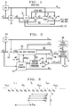
- Figure 1 presents a conventional CELP coder.
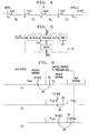
- Figure 2 presents an illustrative embodiment of the present invention.
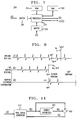
- Figure 3 presents windows of samples used in a correlation process estimating open-loop delay.
- Figure 4 presents illustrative time relationships of delay values for use with the embodiment of Figure 2.
- Figure 5 presents an illustrative embodiment of an adaptive codebook processor.
- Figures 6a-c present illustrative sample time relationships for operation of the adaptive codebook of the embodiment of Figure 2.
- Figure 7 presents an illustrative embodiment of the time-shift processor of the embodiment of Figure 2.
- Figure 8 presents an illustrative set of initial conditions for the operation of the time-shift processor of Figure 7.
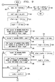
- Figure 9 presents a flow diagram of the operation of the time-shift processor of Figure 7.
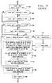
- Figure 10 presents an illustrative segment of original speech used for generating trial original speech signals by time-shifting.
- Figure 11 presents an alternative embodiment of the invention.
- Figure 12 presents a finite state machine describing the operation of a delay estimator as it concerns time synchrony between original and time-shifted signals.
- Figure 13 presents an illustrative receiver/decoder for use with the illustrative coder embodiments presented in Figure 2 and in Figure 11.
- the illustrative embodiment of the present invention is presented as comprising individual functional blocks (including functional blocks labeled as "processors").
- the functions these blocks represent may be realized through the use of either shared or dedicated hardware, including, but not limited to, hardware capable of executing software.
- the functions of processors presented in Figures 5 and 7 may be provided by a single shared processor.
- Illustrative embodiments of the present invention may comprise digital signal processor (DSP) hardware, such as the AT&T DSP16 or DSP32C, read-only memory (ROM) for storing software performing the operations discussed below, and random access memory (RAM) for storing DSP results.
- DSP digital signal processor
- ROM read-only memory
- RAM random access memory
- VLSI Very large scale integration
- a conventional analysis-by-synthesis CELP coder is presented in Figure 1.
- a sampled speech signal, s(i), (where i is the sample index) is provided to a short-term linear prediction filter (STP) 20 of order N , optimized for a current segment of speech.
- Signal x ( i ) is an excitation obtained after filtering with the STP: where parameters a n are provided by linear prediction analyzer 10. Since N is usually about 10 samples (for an 8 kHz sampling rate), the excitation signal x ( i ) generally retains the long-term periodicity of the original signal, s(i).
- An LTP 30 is provided to remove this redundancy.
- Values for x(i) are usually determined on a blockwise basis. Each block is referred to as a subframe .
- the linear prediction coefficients, a n are determined by the analyzer 10 on a frame -by- frame basis, with a frame having a fixed duration which is generally an integral multiple of subframe durations, and usually 20-30 ms in length.
- Subframe values for a n are usually determined through interpolation.
- the LTP determines a gain ⁇ ( i ) and a delay d(i) for use as follows: where the x ⁇ ( i - d ( i )) are samples of a speech signal synthesized (or reconstructed) in earlier subframes.
- the LTP 30 provides the quantity ⁇ ( i ) x ⁇ ( i - d ( i )) .
- Signal r(i) is the excitation signal remaining after ⁇ ( i ) x ⁇ ( i - d ( i )) is subtracted from x ( i ).
- Signal r(i) is then coded with a FSCB 40.
- the FSCB 40 yields an index indicating the codebook vector and an associated scaling factor, ⁇ ( i ). Together these quantities provide an excitation which most closely matches r(i).
- Data representative of each subframe of speech namely, LTP parameters ⁇ ( i ) and d ( i ), and the FSCB index, are collected for the integer number of subframes equalling a frame (typically 2 to 8)). Together with the coefficients a n , this frame of data is communicated to a CELP decoder where it is used in the reconstruction of speech.
- a CELP decoder performs the reverse of the coding process discussed above.
- the FSCB index is received by a FSCB of the receiver (sometimes referred to as a synthesizer) and the associated vector e(i) (an excitation signal) is retrieved from the codebook.
- Excitation e(i) is used to excite an inverse LTP process (wherein long-term correlations are provided) to yield a quantized equivalent of x ( i ), x ⁇ ( i ).
- a reconstructed speech signal, y ( i ) is obtained by filtering x ⁇ ( i ) with an inverse STP process (wherein short-term correlations are provided).
- the reconstructed excitation x ⁇ ( i ) can be interpreted as the sum of scaled contributions from the adaptive and fixed codebooks.
- a perceptually relevant error criterion may be used. This can be done by taking advantage of the spectral masking existing in the human auditory system. Thus, instead of using the difference between the original and reconstructed speech signals, this error criterion considers the difference of perceptually weighted signals.
- the perceptual weighting of signals deemphasizes the formants present in speech.
- the formants are described by an all-pole filter in which spectral deemphasis can be obtained by moving the poles inward. This is equivalent to replacing the filter with predictor coefficients a 1, a 2, ..., a N , by a filter with coefficients ⁇ a 1, ⁇ 2 a 2, ..., ⁇ N a N , where ⁇ is a perceptual weighting factor (usually set to a value around 0.8).
- the sampled error signal in the perceptually weighted domain, g ( i ), is:
- the error criterion of analysis-by-synthesis coders is formulated on a subframe-by-subframe basis. For a subframe length of L samples, a commonly used criterion is: where î is the first sample of the subframe. Note that this criterion weighs the excitation samples unevenly over the subframe; the sample x ⁇ ( i ⁇ + L - 1) affects only g ( i ⁇ + L - 1) , while x ⁇ ( î ) affects all samples of g ( i ) in the present subframe.
- the criterion of equation (4) includes the effects of differences in x ( i ) and x ⁇ ( i ) prior to î , i.e ., prior to the beginning of the present subframe. It is convenient to define an excitation in the present subframe to represent this zero-input response of the weighted synthesis filter: where z ( i ) is the zero-input response in the present subframe of the perceptually-weighted synthesis filter when excited with x ( i )- x ⁇ ( i ) prior to the present subframe.
- the spectral deemphasis by the factor ⁇ results in a quicker attenuation of the impulse response of the all-pole filter.
- the impulse response of the all-pole filter 1/(1 - ⁇ a 1 z ⁇ 1 ... - ⁇ N a N z -N ) can be approximated by a finite-impulse-response filter.
- Let h 0, h 1, ..., h R -1 denote the impulse response of the latter filter. This allows vector notation for the error criterion operating on the perceptually-weighted speech. Because the coders operate on a subframe-by-subframe basis, it is convenient to define vectors with the length of the subframe in samples, L .
- the spectral-weighting matrix H is defined as: H has dimensions ( L + R - 1) ⁇ L .
- the vector approximates the entire response of the IIR filter 1/(1 - ⁇ a 1 z ⁇ 1 ... - ⁇ N a N Z - N ) to the vector x ⁇ ( i ).
- an appropriate perceptually-weighted criterion is:
- the error criterion of equation (8) is of the autocorrelation type (note that H T H is Toeplitz). If the matrix H is truncated to be square L ⁇ L , equation (8) equals equation (4), which is the more common covariance criterion, as used in the original CELP.
- Figure 2 presents an illustrative embodiment of the present invention as it may be applied to CELP coding.
- a speech signal in digital form, s ( i ) is presented for coding.
- Signal s ( i ) is provided to a conventional linear predictive analyzer 100 which produces linear predictive coefficients, a n .
- Signal s ( i ) is also provided to a conventional linear prediction filter (or "short-term predictor" (STP)) 120, which operates according to a process described by Eq. (1), and to a conventional delay estimator 140.
- STP short-term predictor
- Delay estimator 140 operates to provide an estimated delay value to the adaptive codebook processor 150. To determine delay information valid at a particular sample time, delay estimator 140 performs conventional correlation of a window of samples of s(i ), centered about the particular sample in question, with each of a multiplicity of windows of the same length. The windows involved in this correlation are illustrated in Figure 3.
- Figure 3 presents the demarcations for frames ( F ) and constituent subframes ( SF ) of samples of signal s ( i ) (actual sample values of s ( i ) have been omitted for clarity). Shown are three frames, F n -1 (the past frame), F n (the current frame, and F n +1 (the next frame). Each of these frames comprises 160 samples of signal s ( i ).
- Time shift processor 200 provides a sample location dp 1' indicating the end of a subframe of original speech signal, s ( i ).
- Delay estimator 140 simply keeps track of the subframe boundaries of original speech to know when a frame boundary is reached (such a frame boundary is at an integral multiple of subframe boundaries). Because delay estimator 140 operates on a frame of speech prior to the operation of the time shift processor 200 on the same frame of speech, delay estimator 140 must predict the position of future frame boundaries. It does this by adding a fixed number of samples equal to a frame length ( e.g ., 160 samples) to the last frame boundary provided by the time shift processor 200.
- estimator 140 determines a value for delay, M , valid at the boundary between the current and next frames of s ( i ), M ( FB n +1 ). To do this, estimator 140 stores in its memory a window of 160 signal samples surrounding this boundary (estimator 140 must wait to receive samples of signal s ( i ) valid in the next frame). This window of samples is denoted as window A . Next, estimator 140 performs a correlation computation with samples of s ( i ) in window B 1 -- the first of 140 other windows of s ( i ). Window B 1 is a window of 160 samples beginning 20 samples earlier than the beginning of window A and ending 20 samples earlier than the end of window A . A correlation value associated with window B 1 is stored in memory. The correlation process is repeated with window B 2, a 160 sample window beginning one sample earlier in time than window B 1. Correlation computations are performed for each of the next 138 windows, each window distinct from the one before by one sample.
- Delay, M is determined by estimator 140 based on the B window of samples having the greatest correlation with the samples of window A . That is, delay is equal to the number of samples that the most correlated B window is shifted in time from window A .
- the delay estimator 140 determines a frame boundary delay estimate, M , once per frame. Delay estimator 140 further determines a delay value, m , valid at a fixed number of samples into each subframe ( e.g ., 10 samples), by conventional linear interpolation of delay values valid at frame boundaries. For this purpose, the delay value required at 10 samples into the next frame is set equal to the delay value at the frame boundary.
- delay values valid at the frame boundaries surrounding frame n are M ( FB n ) and M ( FB n +1 ).
- Delay values m n ( k ) are provided to the adaptive codebook processor 150. As will be discussed below, the adaptive codebook processor 150 uses this delay information to provide an adaptive codebook contribution to the time shift processor 200.
- the adaptive codebook processor 150 provides an estimate of a current subframe of speech (to be coded) to the time shift processor 200 based on delay estimates, m n ( k ), from the delay estimator 140 and past reconstructed speech signals from the CELP process.
- the adaptive codebook processor 150 operates by using delay values, m n ( k ), to determine a delay pointer, d ( i ), to past reconstructed speech signals stored in the memory of processor 150. Selected past speech samples, x ⁇ ( i ), are then provided to processor 200 as an estimate of the current subframe of speech to be coded.
- adaptive codebook processor 150 For each subframe of original speech to be coded, adaptive codebook processor 150 provides a corresponding subframe of speech samples plus a fixed number of extra samples which extend into the next subframe. Illustratively, this fixed number of extra samples equals 10.
- Figure 5 presents an illustrative realization of the adaptive codebook processor 150.
- the realization comprises processor 155 and RAM 157.
- Processor 155 receives past reconstructed speech signals, x ⁇ ( i ), and stores them in RAM 157 for use in computing current and next subframe speech samples.
- Processor 155 also receives delay values, m n ( k ), from delay estimator 140 which are used in the computation of such sample values.
- Processor 155 provides such computed sample values, x ⁇ ( i ), to time shift processor 200 for use in the generation of trial original signals.
- Each sample of speech provided to the time shift processor 200 is determined as follows. First, a delay pointer, d ( i ), valid for the sample in question (that is, the sample to be provided to the time shift processor 200) is determined by processor 155. This is done by interpolating between a pair of delay values, m n ( k ) (provided by delay estimator 140), which surround the sample in question.
- the interpolation procedure used by processor 155 to provide the delay pointers, d ( i ), is conventional linear interpolation of the provided delay values, m n ( k ).
- processor 155 uses the delay pointer, d ( i ) (valid for the sample in question), as a pointer backward in time to an earlier speech sample which is to be used in the current frame as the value of the sample in question. Such earlier samples are stored in RAM 157.
- the delay pointer, d ( i ) will not point exactly to a past sample. Instead, d ( i ) will likely point somewhere between consecutive past samples.
- processor 155 interpolates past samples to determine a past sample value valid at the moment in time to which the delay pointer refers.
- the interpolation technique used by processor 155 to determine past sample values is conventional bandlimited interpolation, such as that described by Rabiner and Schafer, Digital Processing of Speech Signals , pp. 26-31 (1978).
- the interpolation filter realized by processor 155 illustratively employs 20 taps on either side of the past sample closest to the time indicated by the delay value.
- Figures 6a-c illustrate the process by which the adaptive codebook processor 150 selects past samples for use in a current (and next) subframe. For clarity of presentation, Figures 6a-c assume that a computed value of d ( i ) points exactly to a past sample value, rather to a point in between past sample values. Also, it will be assumed without loss of generality that the delay values are shorter than the subframe length.
- the samples to be provided to time shift processor 200 include samples in a current subframe and a fixed number of samples in the next subframe.
- Processor 155 receives a delay value for the current subframe, m curr , from the delay estimator 140 and has stored in its memory 157 a delay value for the previous subframe, m prev .
- processor 155 determines a delay pointer, d ( i ), valid at the sample time i of the sample in question.
- processor 155 computes by bandlimited interpolation of samples in its memory 157 the sample value valid at a point in time which is d ( i ) samples prior to the sample in question, i.e ., x ⁇ ( i - d ( i )). This sample value is then inserted into a memory location reserved for the current subframe sample in question.
- the subframe length is longer than the delay values.
- the process by which a given sample in the current subframe is determined is based on determining a delay pointer and locking backward in time for a sample value to use as the given sample value.
- segments of reconstructed speech may be essentially repeated using bandlimited interpolation within the current subframe.
- a given sample, x ⁇ ( i ) takes its value from a previously determined sample which precedes it in time by a delay d ( i ), i.e ., x ⁇ ( i - d ( i )).
- This delay is determined as described above, except the delay values which are interpolated are the delays from the current subframe, m curr , and the next subframe, m next , since these delays surround sample x ⁇ ( i ). Repeating signal segments with constant gain when the delay is shorter than the subframe length is what distinguishes the adaptive codebook procedure from LTP filtering procedures.
- the extra samples in the next subframe are determined in the same fashion as those in Figure 6b. In this case, samples from the current subframe are used to provide values for samples in the next subframe.
- the above-described procedure of the adaptive codebook processor 150 may be realized by first computing all delay pointer values, d ( i ) for all sample times of the current and portion of the next subframe in question. Then, for each sample time, i , of the present or next subframe needing a sample value, d ( i ) is used as a reference to a past time, i - d ( i ), at which a sample is "located.” In general, there will not be a sample located at time i - d ( i ). Therefore, bandlimited interpolation of samples surrounding time i - d ( i ) will he required. Once the bandlimited interpolation is performed generating a sample value at i - d ( i ), that sample value is assigned to time i . This process may be repeated in a recursive process for each sample in the present or next subframe as needs
- the adaptive codebook processor 150 has determined samples for use in the current subframe and a fixed portion of the next subframe, those samples are provided to the time shift processor 200 for use as a basis for determining a shifted original signal for use in a CELP coding process.
- the samples provided to the time shift processor are referred to as the adaptive codebook contribution to the analysis-by-synthesis process of CELP coding.
- an all-pole filter may be used in place of the adaptive codebook realization of an LTP.
- the adaptive codebook realization is particularly well suited to situations where, as illustrated here, delay values are generally less than the length of a subframe. This is because a adaptive codebook realization does not require a determined value of LTP gain (here, codebook gain) simply to provide an LTP contribution in the current subframe. This gain may be determined later.
- LTP gain here, codebook gain
- an all-pole filter realization of an LTP requires the solution of a nonlinear equation to obtain a value for the filter gain when delay is less than subframe length.
- the time shift processor 200 determines how to shift segments of an original speech signal such that it may be coded (by an analysis-by-synthesis coding process, such as CELP) with less error than if the original signal was always used for coding.
- the time shift processor 200 first identifies within the original speech signal a local maximum of original speech signal energy.
- processor 200 selects a plurality of overlapping segments of the original speech signal, each of which includes the identified local maximum signal energy.
- Processor 200 compares each selected segment with a segment of the adaptive codebook contribution (provided by the adaptive code book processor 150). This comparison is made to determine the original speech signal segment which most closely matches the segment of the adaptive codebook contribution. When the segment of the original speech signal which best matches the segment of the adaptive codebook contribution is determined, this segment of original speech is used in the formation of a shifted original speech signal for coding by a CELP process.
- time shift processor 200 receives an original residual speech signal, x ( i ), from the STP 120, and provides a time shifted residual, ( i ), for use in the CELP coding process.
- time shift processor 200 illustratively comprises processor 210; conventional buffer memories 220, 230, and 240; conventional ROM 250 for the storage of processor 210 programs; and conventional RAM 260 for the storage of processor 210 results.
- time shift processor 200 will be explained with reference to Figure 8, which presents an illustrative starting point for processor 200 operation on speech signals, and Figure 9, which presents an illustrative flow diagram for the operation of processor 210.
- processor 200 begins operation having received a buffer 220 of reconstructed speech representing the adaptive codebook contribution from the adaptive codebook processor 150.
- this adaptive codebook contribution comprises samples of past reconstructed speech which have been mapped into the current subframe and a fixed portion of the next subframe ( see Figure 6 and associated discussion) by processor 150.
- This buffer of reconstructed speech is loaded into RAM 260 for use by processor 210.
- a pointer, dp 1 is maintained by processor 210 and stored in RAM 260 to indicate the end of the latest subframe for which both the adaptive codebook and FSCB contributions have been determined.
- the length of such subframes, subframe _ l is constant and maintained in memory, e.g ., ROM 250.
- the time shift processor 200 operates to determine a shifted residual signal for the current subframe (and possibly a portion of the next subframe, depending on the circumstances) which best matches the adaptive codebook contribution.
- Figure 9 presents a flow-diagram illustrating the operation of the processor 210 of Figure 7.
- the first task performed by processor 210 is to determine whether the time shifted residual, ( i ), has been extended up to or beyond the end of the current subframe.
- pointer dpm the extent to which the time shifted residual has been extended.
- the end of the current subframe is indicated by the sum of current subframe pointer dp 1 and the fixed subframe length, subframe _ l . If dpm ⁇ dp 1+ subframe _ l further processing is performed to extend the shifted residual; else, no further shift processing is required for the current subframe ( see step 305).
- processor 210 determines the location of maximum energy in a segment of the original residual speech signal, x ( i ) ( see steps 310-375).
- the location of maximum energy corresponds to the location of a pitch-pulse of voiced speech. However, this is not necessarily the case.
- the search for the maximum energy location is made so that shifts in the original signal will be made to best align an energetically significant feature in the original speech with a significant feature in the adaptive codebook contribution.
- the beginning of the segment of the original residual speech signal to be searched is defined with respect to a pointer to an original residual speech signal sample. This sample corresponds to the sample identified by pointer dpm in the shifted residual signal.
- the beginning of the interval to be searched designated by the pointer offset , is then computed (see step 315).
- the length of the interval to be searched is defined ( see step 320).
- the location of maximum energy in the segment of x ( i ) is then determined ( see step 325). This determination is made with use of a five-sample window. This window, centered about the i th sample of the original residual speech signal, defines samples of the original residual used in an energy computation.
- the energy at sample location i is determined by the sum of the squares of the samples in the window.
- the energy at the ( i + 1)th sample location is determined in the same fashion, but with the window moved one sample later in time such that the center window location now contains the ( i + 1)th sample. Again, the energy is determined as the sum of the squares of the sample values in the window.
- the energy of each sample location in the segment is determined in the same fashion.
- the energy of samples in a current window may be determined as the energy of an immediate past window of samples minus the energy of the sample shifted out of the window plus the energy of the sample shifted into the window.
- the sample location having associated with it the maximum energy determined in this fashion is identified by a pointer location .
- processor 210 determines if this maximum energy sample is one which has been considered in the previous subframe (and thus not a maximum of interest). This is done by determining whether location precedes dpm ' (see step 330).
- the value delay is provided by delay estimator 140 as the delay valid at the beginning of the current subframe, M ( FB n ). Since significant pitch-pulse energy features in the original residual signal are likely separated by one delay period, the computation of a new offset allows the search to skip ahead (0.75 delay ) and likely find a maximum energy feature within a segment of length 0.5 delay .
- the sample location of maximum energy is determined as described above with reference to step 325 ( see step 345).
- step 350 If location does not proceed dpm ', then the first pitch-pulse beyond dpm ' has likely been found, and the flow of control jumps to step 350.
- step 350 If the location of maximum signal energy determined at either steps 325 or 345 follows dpm ' + delay , then it is likely, but not certain, that a pitch-pulse located subsequent to dpm ' but prior to dpm ' + delay has been missed by the searches performed to this time by processor 210 ( see step 350). In this case, another segment of the original residual signal is defined and the location of the maximum energy therein is determined. If the location of maximum signal energy determined at either steps 325 or 345 precedes dpm ' + delay , then the flow of control jumps to step 380.
- step 350 results in the need to search another segment of the original residual speech signal
- the location of the maximum energy is determined as described above with reference to step 325, but the sample pointer to this location is saved as location 2 ( see step 365).
- location 2 identifies the location of the first pitch-pulse beyond dpm ', and location is set equal to location 2 (see steps 370 and 375). If, on the other hand, the location of maximum energy is not beyond dpm ', then location 2 is not the first pitch-pulse beyond dpm ', and location remains set to the value it was assigned at either step 325 or 345 (since under such circumstances, pointer location is not overwritten by the operation of step 365).
- a segment of the original residual signal containing this location will be defined by processor 210 through the setting of certain pointers to samples in the signal. These pointers specify the beginning ( s f start ) and end ( s f end ) of this segment containing the determined location . This segment is defined for later use as part of the process of aligning (or shifting) original residual speech to best match an adaptive codebook contribution.
- Pointer s f start is set equal to dpm ', the sample location corresponding to dpm + acc _ shift (see step 380).
- Pointer s f end is set to location + extra .
- the value extra is a constant stored in memory ( e.g ., ROM 250) and is equal to a fixed number of samples, e.g., 10 samples. Use of extra guarantees that the pitch-pulse (or maximum energy) of original residual speech will not fall at the end of the segment of the original residual being identified by these pointers ( see step 380).
- pointer s f end may be overwritten under certain circumstances. If the default value of s f end would mean that the segment of original residual speech would extend significantly beyond the end of the adaptive codebook contribution, the pointer s f end is set to end at dp 1' + subframe _ l + extra , where subframe _ l is a constant equalling the number of samples in a fixed adaptive codebook subframe as discussed above ( see steps 385 and 390).
- s f end may be further overwritten if the location of the identified pitch-pulse (or major energy) is significantly beyond the end of the adaptive codebook subframe. Under such circumstances the segment is deemed to end at the end of the adaptive codebook subframe boundary ( see steps 395 and 400). Note that such a definition of s f end means that the location of the pitch-pulse (or major energy) is later than the end of the segment. Therefore, the segment no longer contains the pitch-pulse.
- the location of the identified pitch-pulse (or maximum energy) is checked to determine whether it falls outside a range of samples beginning at s f start and ending at s f end - 1 (see steps 405). If so, ( i) may be extended with samples obtained with bandlimited interpolation of x ( i ) without need for changing acc _ shift (that is, flow of control may jump to step 480). Otherwise, shifting is performed ( see step 410-475).
- a set (or segment) of L samples of x ( i ) (within a specified range of samples about the segment defined by s f start and s f end ) which most closely matches an L -length section of the adaptive codebook contribution (which begins at dpm and ends at dpm + L ) is determined by processor 210.
- This L-length segment of x ( i ) may comprise those L samples of the segment of x ( i ) defined by s f start and s f end , but may also comprise samples (obtained by bandlimited interpolation) of a segment which is shifted with respect to s f start and s f end , depending upon how closely a given L-length segment of x ( i ) matches the L-length section of x ⁇ ( i ). As predicates to this determination, a limit on the range of possible sample shifts ( see step 410) and a sample length, L , are determined ( see step 415).
- Figure 10 presents an illustrative segment of original residual speech signal x ( i ) which was located as described previously with reference to steps 310-400.
- the segment begins at sample s f start and ends at sample s f end .
- the pitch-pulse is at sample location , with the distance between samples location and s f end equal to extra .
- the samples of x ( i ) falling within the segment defined by pointers s f start and s f end correspond to a shift of zero. Shifted segments of x ( i ) are defined with respect to this zero shift position.
- Each shifted segment is of length L and begins (and ends) a certain positive or negative number of sample lengths (or fractions of sample lengths) with respect to the zero shift position.
- each shifted segment begins at s f start + shift and ends at s f end + shift .
- the range of possible shifts values for shift is ⁇ limit .
- shift - limit .
- the L-length segment of x ( i ) defined by such a shift would begin at location s f start - limit and end at location s f end - limit .
- the L-length segment of x ( i ) defined by such a shift would begin at location s f start + limit and end at location s f end + limit .
- ⁇ limit specifies a range of possible shifts. Therefore, shift may take on values in the range - limit ⁇ shift ⁇ + limit , given a shift step size ( i.e ., shift precision) of sstep .
- Step size sstep may be set illustratively to 0.5 samples. Sample values resulting from fractional shifts are determined by conventional bandlimited interpolation. A plurality of 2 ⁇ limit / sstep segments of the original residual signal x ( i ) may be defined in this way. All are L -length segments between ⁇ limit , wherein each segment overlaps its neighbor segments and is distinct from its nearest neighbor segments by sstep samples.
- limit and extra have an effect on system performance. For example, as extra is made larger, greater coding delay is introduced to the system. As extra is made smaller, coding delay is reduced, but the probability that shift will take on a value which excludes a pitch-pulse from the L-length segment of x ( i ) increases. This exclusion, when it occurs, causes audible distortion in the speech signal. The probability of exclusion is also increased as limit is made larger. To help insure that exclusion does not occur, the value of limit should be less than the value of extra . For example, if the value of extra is 10, limit may be set to 6.
- a measure of similarity between the segment and an L -length segment of the adaptive codebook contribution, x ⁇ ( i ), is computed.
- This computation is illustratively a cross-correlation.
- the adaptive codebook segment used for each cross-correlation begins at dpm and ends at dpm + L (see Figure 8).
- the cross-correlation is performed with a step size equal to sstep (should sstep equal a non-integer value, conventional bandlimited interpolation of x ⁇ ( i ) is performed in advance to provide the requisite sample values for the segments of x ( i ) and x ⁇ ( i )).
- Each cross-correlation results in a cross-correlation value (i.e ., the measure of similarity). All such cross-correlations form a set of cross-correlation values separated in time by sstep . Each cross-correlation value of the set is associated, therefore, with a shift corresponding to the L -length segment of x ( i ) used in the computation of that value.
- the segment of the original residual signal having the greatest cross-correlation with the adaptive codebook segment is determined with an increased time resolution (see step 450).
- this is done by determining a second order polynomial curve for each set of three consecutive cross-correlation values (a set of three values is distinct from its nearest neighboring sets by one value).
- the middle value of these three cross-correlation values in a set corresponds to a shifted original residual signal as described above.
- the set of three cross-correlation values, and thus the associated polynomial curve is identified by this middle value and its associated shift.
- a maximum and the location of that maximum is determined. (If loc _ max is outside the range of the three values, the three values and associated curves are disregarded.)
- the curve having the greatest maximum value identifies the shift of the original residual signal which produces the best match with the segment of the adaptive codebook contribution.
- shift may be refined as shift + sstep * loc _ max .
- the shifted residual signal, x ( i ) is extended to match acc-shift with use of the segment of the original residual signal corresponding to shift .
- original residual sample values are available only at original signal sample times.
- an upsampling has been performed prior to computing cross-correlations and a value loc _ max (which is generally noninteger) has been determined. In general this results in a noninteger sample time relationship between the shifted residual signal ( i ) and the original residual signal x ( i ) to be used in extending the shifted residual signal.
- bandlimited interpolation of the L -length segment of the original signal is used to provide sample values of the original signal which are time-aligned with samples of the shifted residual. Once such time-alignment is performed, the samples of this time-aligned signal may be concatenated with the existing shifted residual signal ( see step 480).
- step 480 flow of control may have jumped to step 480 without updating the accumulated shift.
- a length of L-samples of the original signal is interpolated to provide samples for the shifted residual with the same value of acc _ shift as the previous shifted residual segment.
- dpm is updated to reflect the extension of ( i ) ( see step 490).
- step 305 determines whether further processing is required to extend the shifted residual beyond the end of the current subframe. If so, control flows through the process presented in steps 310-490 of Figure 9 again so that further extension of the shifted residual may be performed. Steps 310-490 are repeated as long as the condition of step 305 is satisfied. Once the shifted residual has been extended up to or beyond the end of the current adaptive codebook subframe, the pointer to the end of the adaptive codebook subframe is updated ( see step 500) and processing associated with time-shifting the original residual ends.
- a scale factor ⁇ ( i ) is determined by process 210 as follows: where ( i) and x ⁇ ( i ) are signals of length equal to a subframe. This scale factor is multiplied by x ⁇ ( i ) and provided as output from processor 200.
- ( i ) and adaptive codebook estimate ⁇ ( i ) x ⁇ ( i ) are supplied to circuit 160 which subtracts estimate ⁇ ( i ) x ⁇ ( i ) from modified original ( i).
- the result is excitation residual signal r ( i ) which is supplied to a fixed stochastic codebook search processor 170.
- Codebook search processor 170 operates conventionally to determine which of the fixed stochastic codebook vectors, z ( i ), scaled by a factor, ⁇ ( i ), most closely matches r ( i ) in a least squares, perceptually weighted sense.
- the chosen scaled fixed codebook vector, ⁇ (i) z min ( i ) is added to the scaled adaptive codebook vector, ⁇ ( i ) x ⁇ ( i ), to yield the best estimate of a current reconstructed speech signal, x ⁇ ( i ). This best estimate, x ⁇ ( i ),is stored by the adaptive codebook processor 150 in its memory.
- adaptive codebook delay and scale factor values, ⁇ and M , a FSCB index, I FC , and gain, ⁇ ( i ), and linear prediction coefficients, a n are communicated across a channel for reconstruction by a conventional CELP decoder/receiver (see Figure 13).
- This communication is in the form of a signal reflecting these parameters.
- adaptive codebook delay information, M once per frame, rather than once per subframe.
- Subframe values for delay may be provided at the receiver by interpolating the delay values in a fashion identical to that done by delay estimator 140 of the transmitter.
- acc_shift represents an accumulated shift over time between the original signal, x ( i ), and the shifted signal, ( i).
- the delay estimator 140 can adjust computed values for M over time. An adjustment process suitable for this purpose carried out by estimator 140 is advantageously described with reference to Figure 12.
- Figure 12 presents a finite-state machine having states A, B and C.
- the state of this machine represents an amount of adjustment to computed values for M to prevent ever increasing asynchrony. Transitions between states are based on values for acc_shift provided by time shift processor 200.
- the delay value M ( FB n +1 ) used to determine values for delays m n ( k ) is not adjusted.
- the finite state machine operates by keeping track of values of acc_shift . If the value of acc_shift is such that a condition for transitioning between the current state and another state is met, a transition to the other state occurs. For example, assuming the machine is in state A (an illustrative initial state for estimator 140) and - 3 ms ⁇ acc _ shift ⁇ 3 ms , the machine would remain in state A and M ( FB n +1 ) would not be modified.
- a trial signal generator 610 receives an original digital speech signal, x ( i ), and generates a plurality of trial original signals, ( i).
- the trial original signal generator 610 comprises a time-shift processor, similar to that presented in Figures 2,7, and 9, but which does not perform a correlation between a trial original signal and an adaptive codebook contribution. Rather, this time shift processor simply provides a plurality of L -length trial original signals based on a plurality of shifts of original speech signal x ( i ).
- these trial original signals are L -length segments of the original signal determined by shifts of step size sstep over a range of ⁇ limit with respect to an L -length segment beginning at sample s f start and ending at sample s f end . Because it performs no cross-correlation between the original residual and trial original signals, generator 610 does not select a trial original signal for coding on its own. Rather it provides the trial original signals, x ( i ), it generates to a coder/synthesizer 620 for processing.
- Coder/synthesizer 620 comprises a conventional analysis-by-synthesis coder, such as the conventional CELP coder presented in Figure 1.
- the synthesized (or reconstructed) original signal, x ⁇ ( i ) is that shown in Figure 1 as the sum of the adaptive and fixed codebook output signals, e ( i )+ ⁇ ( i ) x ( i - d ( i )) (see circuit 45 of Figure 1).
- the coded signal parameters determined by the analysis processing of the CELP coder may be saved in RAM for later use.
- the output of the coder/synthesizer 620, x ⁇ ( i ), is thus an estimate of the original signal, x ( i ), based on a given trial original signal, ( i).
- This estimate of the original signal is thereafter compared with the trial original signal to determine a measure of the similarity between the estimated original, x ⁇ ( i ), and the trial original, ( i).
- This measure similarity is provided to a subtraction circuit 630, which determines a difference (or error) signal, E ( i) , between the two signals.
- the error signal E ( i ) is provided to the trial signal generator 610 which keeps track of the error associated with a given trial original signal.
- the trial signal generator may determine which trial signal, produced the best measure of similarity (e.g ., the smallest error). Thereafter, generator 610 may signal the coder/synthesizer 620 to use the saved code parameters associated with the trial original signal having the smallest error. These parameters may be communicated to a receiver as a coded representation of the original signal, x ( i ).
- references to signals such as the "original” signal, “reconstructed” signal, etc . may include reference to segments thereof. Moreover, whether a given signal is upsampled or not does not change its character as an original” signal, a “trial original” signal, etc . Hence, use of the term “samples” with reference to, e.g. , an "original signal” may include those sample values of the signal provided by an upsampling technique (such as conventional bandlimited interpolation), those samples which are not the result of upsampling, or both.
- an upsampling technique such as conventional bandlimited interpolation
- Attached as an appendix hereto is an illustrative set of software programs related to the fist illustrative embodiment discussed above.
- the software programs of this set are written in the "C" programming language.
- An embodiment of this invention may be provided by executing these programs on a general purpose computer, for example, the Iris Indigo work station marketed by Silicon Graphics, Inc. Note that subroutines "cshiftframe” and “modifyorig" correspond generally to those functions presented in Figure 9.
Abstract
Description
- The present invention relates generally to speech coding systems and more specifically to a reduction of bandwidth requirements in analysis-by-synthesis speech coding systems.
- Speech coding systems function to provide codeword representations of speech signals for communication over a channel or network to one or more system receivers. Each system receiver reconstructs speech signals from received codewords. The amount of codeword information communicated by a system in a given time period defines system bandwidth and affects the quality of speech reproduced by system receivers.
- Designers of speech coding systems often seek to provide high quality speech reproduction capability using as little bandwidth as possible. However, requirements for high quality speech and low bandwidth may conflict and therefore present engineering trade-offs in a design process. This notwithstanding, speech coding techniques have been developed which provide acceptable speech quality at reduced channel bandwidths. Among these are analysis-by-synthesis speech coding techniques.
- With analysis-by-synthesis speech coding techniques, speech signals are coded through a waveform matching procedure. A candidate speech signal is synthesized from one or more parameters for comparison to an original speech signal to be encoded. By varying parameters, different synthesized candidate speech signals may be determined. The parameters of the closest matching candidate speech signal may then be used to represent the original speech signal.
- Many analysis-by-synthesis coders, e.g., most code-excited linear prediction (CELP) coders, employ a long-term predictor (LTP) to model long-term correlations in speech signals. (The term "speech signals" means actual speech or any of the residual and excitation signals present in analysis-by-synthesis coders.) During the synthesis process, an LTP is conventionally realized either as an all-pole filter or as an adaptive codebook with gain scaling. As a general matter, long-term correlations in speech signals allow a past reconstructed speech signal to serve as an approximation of a current speech signal. LTPs work to compare several past speech signals (which have already been coded) to a current (original) speech signal. By such comparisons, the LTP determines which past signal most closely matches the original signal. A past speech signal is identifiable by a delay which indicates how far in the past (from current time) the signal is found. A coder employing an LTP subtracts a scaled version of the closest matching past speech signal (i.e., the best approximation) from the current speech signal to yield a signal with reduced long-term correlation. This signal is then coded, typically with a fixed stochastic codebook (FSCB). The FSCB index and LTP delay, among other parameters, are transmitted to a CELP decoder which can recover an estimate of the original speech from these parameters.
- By modeling long-term correlations of speech, the quality of reconstructed speech at a decoder may be enhanced. This enhancement, however, is not achieved without a significant increase in bandwidth. For example, in order to model long-term correlations in speech, conventional CELP coders may transmit 8-bit delay information every 5 or 7.5 ms (referred to as a subframe). Such time-varying delay parameters require, e.g., between one and two additional kilobits (kb) per second of bandwidth. Because variations in LTP delay may not be predictable over time (i.e., a sequence of LTP delay values may be stochastic in nature), it may prove difficult to reduce the additional bandwidth requirement through improved coding of delay parameters.
- One approach to reducing the extra bandwidth requirements of analysis-by-synthesis coders employing an LTP might be to transmit LTP delay values less often and determine intermediate LTP delay values by interpolation. However, interpolation may lead to suboptimal delay values being used by the LTP in individual subframes of the speech signal. For example, if the delay is suboptimal, then the LTP will map past speech signals into the present in a suboptimal fashion. As a result, the difference between past speech mapped into the present and the original signal will be larger than it might otherwise be. The FSCB must then work to undo the effects of this suboptimal time-shift rather than perform its normal function of refining waveform shape. As a result, significant audible distortion may result.
- The present invention provides a method and apparatus for reducing bandwidth requirements in analysis-by-synthesis coding systems. In accordance with the present invention, generalized analysis-by-synthesis coding is provided through variation of original signals. Original signal variants are referred to as trial original signals. Use of trial original signals in place of or as a supplement to the use of original signals in analysis-by-synthesis coding reduces coding error and bit rate requirements. In the context of speech coding, reduced coding error affords less frequent transmission of LTP delay information and allows for delay interpolation with little or no degradation in the quality of reconstructed speech. The invention is applicable to, among other things, networks for communicating speech information, such as, for example, wireless (e.g., cellular) and conventional telephone networks.
- Regarding speech coding, trial original signals are illustratively signals which are perceptually (e.g., audibly) similar to the actual original signal. The degree of audible similarity between a trial original signal and the actual original signal may affect coded bit rate and the quality of speech synthesized by a receiver (e.g., the lower the similarity, the lower the bit rate and speech quality may be). The original signal, and hence the trial original signals, may take the form of actual speech signals or any of the residual or excitation signals present in analysis-by-synthesis coders.
- In an illustrative embodiment of the present invention, trial original signals are generated as time-shifted versions of an original speech signal segment. Measures of similarity (e.g., cross-correlations) between trial original signals and contributions from an adaptive codebook are evaluate A trial original signal which is either the same as one of the trial original signals or a variant of an original or trial original signal is determined based on one or more evaluated measures of similarity. (In the case of a variant of previously generated trial original signals, the determined trial original signal (i.e., the variant) may correspond to a time-shift which falls in between time-shifts which produced previously generated trial original signals.) A signal reflecting a coded representation of the original signal is generated based on the determined trial original signal.
- Figure 1 presents a conventional CELP coder.
- Figure 2 presents an illustrative embodiment of the present invention.
- Figure 3 presents windows of samples used in a correlation process estimating open-loop delay.
- Figure 4 presents illustrative time relationships of delay values for use with the embodiment of Figure 2.
- Figure 5 presents an illustrative embodiment of an adaptive codebook processor.
- Figures 6a-c present illustrative sample time relationships for operation of the adaptive codebook of the embodiment of Figure 2.
- Figure 7 presents an illustrative embodiment of the time-shift processor of the embodiment of Figure 2.
- Figure 8 presents an illustrative set of initial conditions for the operation of the time-shift processor of Figure 7.
- Figure 9 presents a flow diagram of the operation of the time-shift processor of Figure 7.
- Figure 10 presents an illustrative segment of original speech used for generating trial original speech signals by time-shifting.
- Figure 11 presents an alternative embodiment of the invention.
- Figure 12 presents a finite state machine describing the operation of a delay estimator as it concerns time synchrony between original and time-shifted signals.
- Figure 13 presents an illustrative receiver/decoder for use with the illustrative coder embodiments presented in Figure 2 and in Figure 11.
- For clarity of explanation, the illustrative embodiment of the present invention is presented as comprising individual functional blocks (including functional blocks labeled as "processors"). The functions these blocks represent may be realized through the use of either shared or dedicated hardware, including, but not limited to, hardware capable of executing software. For example, the functions of processors presented in Figures 5 and 7 may be provided by a single shared processor. (Use of the term "processor" should not be construed to refer exclusively to hardware capable of executing software.)
Illustrative embodiments of the present invention may comprise digital signal processor (DSP) hardware, such as the AT&T DSP16 or DSP32C, read-only memory (ROM) for storing software performing the operations discussed below, and random access memory (RAM) for storing DSP results. Very large scale integration (VLSI) hardware embodiments, as well as custom VLSI circuitry in combination with a general purpose DSP circuit, may also be provided. - A conventional analysis-by-synthesis CELP coder is presented in Figure 1. A sampled speech signal, s(i), (where i is the sample index) is provided to a short-term linear prediction filter (STP) 20 of order N, optimized for a current segment of speech. Signal x(i) is an excitation obtained after filtering with the STP:

where parameters a n are provided bylinear prediction analyzer 10. Since N is usually about 10 samples (for an 8 kHz sampling rate), the excitation signal x(i) generally retains the long-term periodicity of the original signal, s(i). AnLTP 30 is provided to remove this redundancy. - Values for x(i) are usually determined on a blockwise basis. Each block is referred to as a subframe. The linear prediction coefficients, a n , are determined by the
analyzer 10 on a frame-by-frame basis, with a frame having a fixed duration which is generally an integral multiple of subframe durations, and usually 20-30 ms in length. Subframe values for a n are usually determined through interpolation. - The LTP, typically implemented with an adaptive codebook, determines a gain λ(i) and a delay d(i) for use as follows:

where the
LTP 30 provides the quantity

FSCB 40. TheFSCB 40 yields an index indicating the codebook vector and an associated scaling factor, µ(i). Together these quantities provide an excitation which most closely matches r(i). - Data representative of each subframe of speech, namely, LTP parameters λ(i) and d(i), and the FSCB index, are collected for the integer number of subframes equalling a frame (typically 2 to 8). Together with the coefficients a n , this frame of data is communicated to a CELP decoder where it is used in the reconstruction of speech.
- A CELP decoder performs the reverse of the coding process discussed above. The FSCB index is received by a FSCB of the receiver (sometimes referred to as a synthesizer) and the associated vector e(i) (an excitation signal) is retrieved from the codebook. Excitation e(i) is used to excite an inverse LTP process (wherein long-term correlations are provided) to yield a quantized equivalent of x(i), x̂(i). A reconstructed speech signal, y(i), is obtained by filtering x̂(i) with an inverse STP process (wherein short-term correlations are provided).
- In general, the reconstructed excitation x̂(i) can be interpreted as the sum of scaled contributions from the adaptive and fixed codebooks. To select the vectors from these codebooks, a perceptually relevant error criterion may be used. This can be done by taking advantage of the spectral masking existing in the human auditory system. Thus, instead of using the difference between the original and reconstructed speech signals, this error criterion considers the difference of perceptually weighted signals.
- The perceptual weighting of signals deemphasizes the formants present in speech. In this example, the formants are described by an all-pole filter in which spectral deemphasis can be obtained by moving the poles inward. This is equivalent to replacing the filter with predictor coefficients a₁, a₂, ..., a N , by a filter with coefficients γa₁, γ²a 2, ..., γ N a N , where γ is a perceptual weighting factor (usually set to a value around 0.8).
- The sampled error signal in the perceptually weighted domain, g(i), is:

The error criterion of analysis-by-synthesis coders is formulated on a subframe-by-subframe basis. For a subframe length of L samples, a commonly used criterion is:
where î is the first sample of the subframe. Note that this criterion weighs the excitation samples unevenly over the subframe; the sample

- The criterion of equation (4) includes the effects of differences in x(i) and x̂(i) prior to î, i.e., prior to the beginning of the present subframe. It is convenient to define an excitation in the present subframe to represent this zero-input response of the weighted synthesis filter:

where z(i) is the zero-input response in the present subframe of the perceptually-weighted synthesis filter when excited with x(i)-x̂(i) prior to the present subframe. - In the time-domain, the spectral deemphasis by the factor γ results in a quicker attenuation of the impulse response of the all-pole filter. In practice, for a sampling rate of 8 kHz, and γ = 0.8, the impulse response never has a significant part of its energy beyond 20 samples.
- Because of its fast decay, the impulse response of the all-
pole filter 1/(1 - γa₁z⁻¹ ... - γ N a N z -N )can be approximated by a finite-impulse-response filter. Let h₀, h₁, ..., h R -1 denote the impulse response of the latter filter. This allows vector notation for the error criterion operating on the perceptually-weighted speech. Because the coders operate on a subframe-by-subframe basis, it is convenient to define vectors with the length of the subframe in samples, L. For example, for the excitation signal:
Further, the spectral-weighting matrix H is defined as:
H has dimensions

approximates the entire response of theIIR filter 1/(1 - γa₁z⁻¹ ... - γ N a N Z -N ) to the vector x̂(i). With these definitions an appropriate perceptually-weighted criterion is:
With the current definition of H the error criterion of equation (8) is of the autocorrelation type (note that H T H is Toeplitz). If the matrix H is truncated to be square L×L, equation (8) equals equation (4), which is the more common covariance criterion, as used in the original CELP. - Figure 2 presents an illustrative embodiment of the present invention as it may be applied to CELP coding. A speech signal in digital form, s(i), is presented for coding. Signal s(i) is provided to a conventional linear
predictive analyzer 100 which produces linear predictive coefficients, a n . Signal s(i) is also provided to a conventional linear prediction filter (or "short-term predictor" (STP)) 120, which operates according to a process described by Eq. (1), and to aconventional delay estimator 140. -
Delay estimator 140 operates to provide an estimated delay value to theadaptive codebook processor 150. To determine delay information valid at a particular sample time,delay estimator 140 performs conventional correlation of a window of samples of s(i), centered about the particular sample in question, with each of a multiplicity of windows of the same length. The windows involved in this correlation are illustrated in Figure 3. - Figure 3 presents the demarcations for frames (F) and constituent subframes (SF) of samples of signal s(i) (actual sample values of s(i) have been omitted for clarity). Shown are three frames, F n -1 (the past frame), F n (the current frame, and F n +1(the next frame). Each of these frames comprises 160 samples of signal s(i).
- The location of frame boundaries is provided by
time shift processor 200 discussed below.Time shift processor 200 provides a sample location dp 1' indicating the end of a subframe of original speech signal, s(i).Delay estimator 140 simply keeps track of the subframe boundaries of original speech to know when a frame boundary is reached (such a frame boundary is at an integral multiple of subframe boundaries). Becausedelay estimator 140 operates on a frame of speech prior to the operation of thetime shift processor 200 on the same frame of speech,delay estimator 140 must predict the position of future frame boundaries. It does this by adding a fixed number of samples equal to a frame length (e.g., 160 samples) to the last frame boundary provided by thetime shift processor 200. - Assume
delay estimator 140 is to determine a value for delay, M, valid at the boundary between the current and next frames of s(i), M(FB n +1). To do this,estimator 140 stores in its memory a window of 160 signal samples surrounding this boundary (estimator 140 must wait to receive samples of signal s(i) valid in the next frame). This window of samples is denoted as window A. Next,estimator 140 performs a correlation computation with samples of s(i) in window B₁ -- the first of 140 other windows of s(i). Window B₁ is a window of 160 samples beginning 20 samples earlier than the beginning of window A and ending 20 samples earlier than the end of window A. A correlation value associated with window B₁ is stored in memory. The correlation process is repeated with window B₂, a 160 sample window beginning one sample earlier in time than window B₁. Correlation computations are performed for each of the next 138 windows, each window distinct from the one before by one sample. - As shown in Figure 3,
estimator 140 must have enough memory to store what is essentially two frames of signal samples. If D is the largest delay value allowed, then the memory should extend D samples prior to the beginning of window A. When D=160, in order to compute an estimated delay valid at FB n +1,estimator 140 must store samples of s(i) from the beginning of the third subframe, SF₂, of frame F n -1 to the end of the second subframe, SF₁, of frame F n +1. Delay, M, is determined byestimator 140 based on the B window of samples having the greatest correlation with the samples of window A. That is, delay is equal to the number of samples that the most correlated B window is shifted in time from window A. - The
delay estimator 140 determines a frame boundary delay estimate, M, once per frame.Delay estimator 140 further determines a delay value, m, valid at a fixed number of samples into each subframe (e.g., 10 samples), by conventional linear interpolation of delay values valid at frame boundaries. For this purpose, the delay value required at 10 samples into the next frame is set equal to the delay value at the frame boundary. - The timing associated with the delay values provided by
delay estimator 140 is illustrated in Figure 4. As shown in the Figure, delay values valid at the frame boundaries surrounding frame n are M(FB n ) and M(FB n +1). Delay values valid at a fixed number of samples past each subframe boundary (SB) within frame n are indicated as m n (k), k=0,1,2,3. These values of m n (k) are determined by interpolation as discussed above. Delay values m n (k) are provided to theadaptive codebook processor 150. As will be discussed below, theadaptive codebook processor 150 uses this delay information to provide an adaptive codebook contribution to thetime shift processor 200. - The
adaptive codebook processor 150 provides an estimate of a current subframe of speech (to be coded) to thetime shift processor 200 based on delay estimates, m n (k), from thedelay estimator 140 and past reconstructed speech signals from the CELP process. Theadaptive codebook processor 150 operates by using delay values, m n (k), to determine a delay pointer, d(i), to past reconstructed speech signals stored in the memory ofprocessor 150. Selected past speech samples, x̂(i), are then provided toprocessor 200 as an estimate of the current subframe of speech to be coded. For each subframe of original speech to be coded,adaptive codebook processor 150 provides a corresponding subframe of speech samples plus a fixed number of extra samples which extend into the next subframe. Illustratively, this fixed number of extra samples equals 10. - Figure 5 presents an illustrative realization of the
adaptive codebook processor 150. The realization comprisesprocessor 155 andRAM 157.Processor 155 receives past reconstructed speech signals, x̂(i), and stores them inRAM 157 for use in computing current and next subframe speech samples.Processor 155 also receives delay values, m n (k), fromdelay estimator 140 which are used in the computation of such sample values.Processor 155 provides such computed sample values, x̂(i), totime shift processor 200 for use in the generation of trial original signals. - Each sample of speech provided to the
time shift processor 200 is determined as follows. First, a delay pointer, d(i), valid for the sample in question (that is, the sample to be provided to the time shift processor 200) is determined byprocessor 155. This is done by interpolating between a pair of delay values, m n (k) (provided by delay estimator 140), which surround the sample in question. The interpolation procedure used byprocessor 155 to provide the delay pointers, d(i), is conventional linear interpolation of the provided delay values, m n (k). Next,processor 155 uses the delay pointer, d(i) (valid for the sample in question), as a pointer backward in time to an earlier speech sample which is to be used in the current frame as the value of the sample in question. Such earlier samples are stored inRAM 157. In general, the delay pointer, d(i), will not point exactly to a past sample. Instead, d(i) will likely point somewhere between consecutive past samples. Under such circumstances,processor 155 interpolates past samples to determine a past sample value valid at the moment in time to which the delay pointer refers. The interpolation technique used byprocessor 155 to determine past sample values is conventional bandlimited interpolation, such as that described by Rabiner and Schafer, Digital Processing of Speech Signals, pp. 26-31 (1978). The interpolation filter realized byprocessor 155 illustratively employs 20 taps on either side of the past sample closest to the time indicated by the delay value. - Figures 6a-c illustrate the process by which the
adaptive codebook processor 150 selects past samples for use in a current (and next) subframe. For clarity of presentation, Figures 6a-c assume that a computed value of d(i) points exactly to a past sample value, rather to a point in between past sample values. Also, it will be assumed without loss of generality that the delay values are shorter than the subframe length. - As shown in Figure 6a, the samples to be provided to
time shift processor 200 include samples in a current subframe and a fixed number of samples in the next subframe.Processor 155 receives a delay value for the current subframe, m curr , from thedelay estimator 140 and has stored in its memory 157 a delay value for the previous subframe, m prev . To determine the value of each sample, x̂(i), of the current subframe located prior to the point at which m curr is valid,processor 155 determines a delay pointer, d(i), valid at the sample time i of the sample in question. This is done by linear interpolation to the point in time when the sample is valid using delay m curr , and the last delay value received fromestimator 140, m prev . After this delay pointer, d(i), has been determined,processor 155 computes by bandlimited interpolation of samples in itsmemory 157 the sample value valid at a point in time which is d(i) samples prior to the sample in question, i.e., x̂(i-d(i)). This sample value is then inserted into a memory location reserved for the current subframe sample in question. - In the example of Figure 6, the subframe length is longer than the delay values. The process by which a given sample in the current subframe is determined is based on determining a delay pointer and locking backward in time for a sample value to use as the given sample value. Thus, segments of reconstructed speech may be essentially repeated using bandlimited interpolation within the current subframe. So, for example, in Figure 6b, a given sample, x̂(i), takes its value from a previously determined sample which precedes it in time by a delay d(i), i.e., x̂(i-d(i)). This delay is determined as described above, except the delay values which are interpolated are the delays from the current subframe, m curr , and the next subframe, m next , since these delays surround sample x̂(i). Repeating signal segments with constant gain when the delay is shorter than the subframe length is what distinguishes the adaptive codebook procedure from LTP filtering procedures.
- As shown in Figure 6c, the extra samples in the next subframe are determined in the same fashion as those in Figure 6b. In this case, samples from the current subframe are used to provide values for samples in the next subframe.
- In practice, the above-described procedure of the
adaptive codebook processor 150 may be realized by first computing all delay pointer values, d(i) for all sample times of the current and portion of the next subframe in question. Then, for each sample time, i, of the present or next subframe needing a sample value, d(i) is used as a reference to a past time, i-d(i), at which a sample is "located." In general, there will not be a sample located at time i-d(i). Therefore, bandlimited interpolation of samples surrounding time i-d(i) will he required. Once the bandlimited interpolation is performed generating a sample value at i-d(i), that sample value is assigned to time i. This process may be repeated in a recursive process for each sample in the present or next subframe as needs - Once the
adaptive codebook processor 150 has determined samples for use in the current subframe and a fixed portion of the next subframe, those samples are provided to thetime shift processor 200 for use as a basis for determining a shifted original signal for use in a CELP coding process. The samples provided to the time shift processor are referred to as the adaptive codebook contribution to the analysis-by-synthesis process of CELP coding. - It should be understood that an all-pole filter may be used in place of the adaptive codebook realization of an LTP. However, the adaptive codebook realization is particularly well suited to situations where, as illustrated here, delay values are generally less than the length of a subframe. This is because a adaptive codebook realization does not require a determined value of LTP gain (here, codebook gain) simply to provide an LTP contribution in the current subframe. This gain may be determined later. Unlike the case of the adaptive codebook, an all-pole filter realization of an LTP requires the solution of a nonlinear equation to obtain a value for the filter gain when delay is less than subframe length.
- The
time shift processor 200 determines how to shift segments of an original speech signal such that it may be coded (by an analysis-by-synthesis coding process, such as CELP) with less error than if the original signal was always used for coding. To time-shift an original speech signal, thetime shift processor 200 first identifies within the original speech signal a local maximum of original speech signal energy. In the illustrative embodiment described below,processor 200 selects a plurality of overlapping segments of the original speech signal, each of which includes the identified local maximum signal energy.Processor 200 compares each selected segment with a segment of the adaptive codebook contribution (provided by the adaptive code book processor 150). This comparison is made to determine the original speech signal segment which most closely matches the segment of the adaptive codebook contribution. When the segment of the original speech signal which best matches the segment of the adaptive codebook contribution is determined, this segment of original speech is used in the formation of a shifted original speech signal for coding by a CELP process. - As shown in Figure 2, the
time shift processor 200 receives an original residual speech signal, x(i), from theSTP 120, and provides a time shifted residual,(i), for use in the CELP coding process. As shown in Figure 7,
time shift processor 200 illustratively comprisesprocessor 210;conventional buffer memories conventional ROM 250 for the storage ofprocessor 210 programs; andconventional RAM 260 for the storage ofprocessor 210 results. - The operation of
time shift processor 200 will be explained with reference to Figure 8, which presents an illustrative starting point forprocessor 200 operation on speech signals, and Figure 9, which presents an illustrative flow diagram for the operation ofprocessor 210. - As shown in Figure 8,
processor 200 begins operation having received abuffer 220 of reconstructed speech representing the adaptive codebook contribution from theadaptive codebook processor 150. As discussed above, this adaptive codebook contribution comprises samples of past reconstructed speech which have been mapped into the current subframe and a fixed portion of the next subframe (see Figure 6 and associated discussion) byprocessor 150. This buffer of reconstructed speech is loaded intoRAM 260 for use byprocessor 210. A pointer,dp 1, is maintained byprocessor 210 and stored inRAM 260 to indicate the end of the latest subframe for which both the adaptive codebook and FSCB contributions have been determined. The length of such subframes, subframe_l, is constant and maintained in memory, e.g.,ROM 250. Based on prior operation of theprocessor 210, a time shifted residual,(i), has been created up to a point in time identified by a pointer dpm (pointer dpm is always greater than or equal to dp 1). Moreover, a portion of the original residual signal, x(i), including that associated with the current subframe, has been received by
buffer 230 and stored inRAM 260.Processor 210 maintains (in RAM 260) a value, acc_shift, representing the sample displacement (or accumulated shift) between the last sample in the shifted residual signal and a corresponding sample in the original residual speech signal. (At initialization, the above-described status is modified to include

- Given this set of conditions, the
time shift processor 200 operates to determine a shifted residual signal for the current subframe (and possibly a portion of the next subframe, depending on the circumstances) which best matches the adaptive codebook contribution. - Figure 9 presents a flow-diagram illustrating the operation of the
processor 210 of Figure 7. According to Figure 9, the first task performed byprocessor 210 is to determine whether the time shifted residual,(i), has been extended up to or beyond the end of the current subframe. As shown in Figure 8, the extent to which the time shifted residual has been extended is given by pointer dpm. The end of the current subframe is indicated by the sum of currentsubframe pointer dp 1 and the fixed subframe length, subframe_l. If dpm <dp 1+subframe_l further processing is performed to extend the shifted residual; else, no further shift processing is required for the current subframe (see step 305). - If further shift processing is required,
processor 210 determines the location of maximum energy in a segment of the original residual speech signal, x(i) (see steps 310-375). Ordinarily, the location of maximum energy corresponds to the location of a pitch-pulse of voiced speech. However, this is not necessarily the case. Regardless of whether the maximum energy is associated with a pitch-pulse or some other signal feature (such as, e.g., energetic noise), the search for the maximum energy location is made so that shifts in the original signal will be made to best align an energetically significant feature in the original speech with a significant feature in the adaptive codebook contribution. - The beginning of the segment of the original residual speech signal to be searched is defined with respect to a pointer to an original residual speech signal sample. This sample corresponds to the sample identified by pointer dpm in the shifted residual signal. This residual speech signal sample pointer, dpm', is determined as the sum of sample pointer dpm and the accumulated shift between(i) and x(i): dpm'=dpm+acc shift (see step 310). The beginning of the interval to be searched, designated by the pointer offset, is then computed (see step 315). Next, the length of the interval to be searched is defined (see step 320).
- The location of maximum energy in the segment of x(i) is then determined (see step 325). This determination is made with use of a five-sample window. This window, centered about the ith sample of the original residual speech signal, defines samples of the original residual used in an energy computation. The energy at sample location i is determined by the sum of the squares of the samples in the window. The energy at the (i + 1)th sample location is determined in the same fashion, but with the window moved one sample later in time such that the center window location now contains the (i + 1)th sample. Again, the energy is determined as the sum of the squares of the sample values in the window. The energy of each sample location in the segment is determined in the same fashion. The energy of samples in a current window may be determined as the energy of an immediate past window of samples minus the energy of the sample shifted out of the window plus the energy of the sample shifted into the window. The sample location having associated with it the maximum energy determined in this fashion is identified by a pointer location.
- Once the segment of the original residual signal, x(i), has been searched for the sample having the maximum energy in the segment,
processor 210 determines if this maximum energy sample is one which has been considered in the previous subframe (and thus not a maximum of interest). This is done by determining whether location precedes dpm' (see step 330). - If location precedes dpm', another search is performed by
processor 210. In this case, however, the segment searched begins at a sample specified as offset = location + 0.75 delay (see step 335), and is ofduration 0. 5 delay. The value delay is provided bydelay estimator 140 as the delay valid at the beginning of the current subframe, M(FB n ). Since significant pitch-pulse energy features in the original residual signal are likely separated by one delay period, the computation of a new offset allows the search to skip ahead (0.75 delay) and likely find a maximum energy feature within a segment of length 0.5 delay. The sample location of maximum energy is determined as described above with reference to step 325 (see step 345). - If location does not proceed dpm', then the first pitch-pulse beyond dpm' has likely been found, and the flow of control jumps to step 350.
- If the location of maximum signal energy determined at either
steps steps - Assuming
step 350 results in the need to search another segment of the original residual speech signal, this segment is determined to begin at
- If the location of maximum energy (location 2) is subsequent to dpm', then
location 2 identifies the location of the first pitch-pulse beyond dpm', and location is set equal to location 2 (seesteps 370 and 375). If, on the other hand, the location of maximum energy is not beyond dpm', thenlocation 2 is not the first pitch-pulse beyond dpm', and location remains set to the value it was assigned at either step 325 or 345 (since under such circumstances, pointer location is not overwritten by the operation of step 365). - At this point, the location of the first pitch-pulse (or energy maximum) in a segment of the original residual has been found. Now, a segment of the original residual signal containing this location will be defined by
processor 210 through the setting of certain pointers to samples in the signal. These pointers specify the beginning (s f start) and end (s f end) of this segment containing the determined location. This segment is defined for later use as part of the process of aligning (or shifting) original residual speech to best match an adaptive codebook contribution. - First, default values for the segment pointers are set by
processor 210. Pointer s f start is set equal to dpm', the sample location corresponding to dpm + acc_shift (see step 380). This value for s f start corresponds to an additional accumulated shift between x(i) and(i ) of zero. That is, use of a section of x(i) beginning at dpm' (= s f start) adds nothing to the accumulated shift between the original and shifted residual signals. - Pointer s f end is set to location + extra. The value extra is a constant stored in memory (e.g., ROM 250) and is equal to a fixed number of samples, e.g., 10 samples. Use of extra guarantees that the pitch-pulse (or maximum energy) of original residual speech will not fall at the end of the segment of the original residual being identified by these pointers (see step 380).
- The default value of pointer s f end may be overwritten under certain circumstances. If the default value of s f end would mean that the segment of original residual speech would extend significantly beyond the end of the adaptive codebook contribution, the pointer s f end is set to end at dp 1' + subframe_l + extra, where subframe_l is a constant equalling the number of samples in a fixed adaptive codebook subframe as discussed above (see
steps 385 and 390). - The value of s f end may be further overwritten if the location of the identified pitch-pulse (or major energy) is significantly beyond the end of the adaptive codebook subframe. Under such circumstances the segment is deemed to end at the end of the adaptive codebook subframe boundary (see
steps 395 and 400). Note that such a definition of s f end means that the location of the pitch-pulse (or major energy) is later than the end of the segment. Therefore, the segment no longer contains the pitch-pulse. - At this point, the location of the identified pitch-pulse (or maximum energy) is checked to determine whether it falls outside a range of samples beginning at s f start and ending at s f end - 1 (see steps 405). If so,(i) may be extended with samples obtained with bandlimited interpolation of x(i) without need for changing acc_shift (that is, flow of control may jump to step 480). Otherwise, shifting is performed (see step 410-475).
- Assuming the location of the identified pitch-pulse (or major energy) is not outside the range defined above, a set (or segment) of L samples of x(i) (within a specified range of samples about the segment defined by s f start and s f end) which most closely matches an L-length section of the adaptive codebook contribution (which begins at dpm and ends at dpm+L) is determined by
processor 210. - This L-length segment of x(i) may comprise those L samples of the segment of x(i) defined by s f start and s f end, but may also comprise samples (obtained by bandlimited interpolation) of a segment which is shifted with respect to s f start and s f end, depending upon how closely a given L-length segment of x(i) matches the L-length section of x̂(i). As predicates to this determination, a limit on the range of possible sample shifts (see step 410) and a sample length, L, are determined (see step 415). The determination of the "closeness" (i.e., a measure of similarity) between L-length segments of x(i) and the adaptive codebook contribution x̂(i) is made through a cross-correlation process of these signals (see step 425) (it will be understood that other measures of similarity, such as a difference or error signal may also be used). The selection of L-length segments of x(i) for use in a cross-correlation with a segment of x̂(i) may be advantageously described with reference to Figure 10.
- Figure 10 presents an illustrative segment of original residual speech signal x(i) which was located as described previously with reference to steps 310-400. The segment begins at sample s f start and ends at sample s f end. The pitch-pulse is at sample location, with the distance between samples location and s f end equal to extra. As discussed above, the samples of x(i) falling within the segment defined by pointers s f start and s f end correspond to a shift of zero. Shifted segments of x(i) are defined with respect to this zero shift position. Each shifted segment is of length L and begins (and ends) a certain positive or negative number of sample lengths (or fractions of sample lengths) with respect to the zero shift position. Expressed another way, each shifted segment begins at s f start + shift and ends at s f end + shift. As shown in Figure 10, the range of possible shifts values for shift is ±limit.
- So for example, one possible shift would be shift = - limit. In this case, the L-length segment of x(i) defined by such a shift would begin at location s f start - limit and end at location s f end - limit. Similarly, another possible shift would be shift = + limit. In this case, the L-length segment of x(i) defined by such a shift would begin at location s f start + limit and end at location s f end + limit. As mentioned above, ±limit specifies a range of possible shifts. Therefore, shift may take on values in the range - limit≦shift≦+limit, given a shift step size (i.e., shift precision) of sstep. Step size sstep may be set illustratively to 0.5 samples. Sample values resulting from fractional shifts are determined by conventional bandlimited interpolation. A plurality of 2×limit/sstep segments of the original residual signal x(i) may be defined in this way. All are L-length segments between ±limit, wherein each segment overlaps its neighbor segments and is distinct from its nearest neighbor segments by sstep samples.
- The relative sizes of limit and extra have an effect on system performance. For example, as extra is made larger, greater coding delay is introduced to the system. As extra is made smaller, coding delay is reduced, but the probability that shift will take on a value which excludes a pitch-pulse from the L-length segment of x(i) increases. This exclusion, when it occurs, causes audible distortion in the speech signal. The probability of exclusion is also increased as limit is made larger. To help insure that exclusion does not occur, the value of limit should be less than the value of extra. For example, if the value of extra is 10, limit may be set to 6.
- For each such L-length segment of x(i) thus identified, a measure of similarity between the segment and an L-length segment of the adaptive codebook contribution, x̂(i), is computed. This computation is illustratively a cross-correlation. The adaptive codebook segment used for each cross-correlation begins at dpm and ends at dpm+L (see Figure 8). The cross-correlation is performed with a step size equal to sstep (should sstep equal a non-integer value, conventional bandlimited interpolation of x̂(i) is performed in advance to provide the requisite sample values for the segments of x(i) and x̂(i)). Each cross-correlation results in a cross-correlation value (i.e., the measure of similarity). All such cross-correlations form a set of cross-correlation values separated in time by sstep. Each cross-correlation value of the set is associated, therefore, with a shift corresponding to the L-length segment of x(i) used in the computation of that value.
- Once the set of cross-correlation values is determined, the segment of the original residual signal having the greatest cross-correlation with the adaptive codebook segment is determined with an increased time resolution (see step 450). Illustratively, this is done by determining a second order polynomial curve for each set of three consecutive cross-correlation values (a set of three values is distinct from its nearest neighboring sets by one value). The middle value of these three cross-correlation values in a set corresponds to a shifted original residual signal as described above. The set of three cross-correlation values, and thus the associated polynomial curve, is identified by this middle value and its associated shift. For each such curve, a maximum and the location of that maximum (loc_max) is determined. (If loc_max is outside the range of the three values, the three values and associated curves are disregarded.) The curve having the greatest maximum value identifies the shift of the original residual signal which produces the best match with the segment of the adaptive codebook contribution.
- The shift of the original residual signal producing the best match is refined with knowledge of the location of the maximum of the polynomial curve having the greatest maximum. With the location of the maximum defined with respect to the location of the middle of the three cross-correlation values associated with the curve (i.e., a value of shift), shift may be refined as

- At this point, the best shift of the original residual signal has been determined. This shift may then be used to extend the shifted residual,(i) for a duration L. Since this shift is known, the accumulated shift between the original residual signal, x(i), and the shifted residual signal,(i) may be updated as

- With the accumulated shift updated, the shifted residual signal, x(i), is extended to match acc-shift with use of the segment of the original residual signal corresponding to shift. Note that original residual sample values are available only at original signal sample times. However, in determining an optimal shift of the original residual signal, an upsampling has been performed prior to computing cross-correlations and a value loc_max (which is generally noninteger) has been determined. In general this results in a noninteger sample time relationship between the shifted residual signal(i) and the original residual signal x(i) to be used in extending the shifted residual signal. Therefore, bandlimited interpolation of the L-length segment of the original signal is used to provide sample values of the original signal which are time-aligned with samples of the shifted residual. Once such time-alignment is performed, the samples of this time-aligned signal may be concatenated with the existing shifted residual signal (see step 480).
- Note that flow of control may have jumped to step 480 without updating the accumulated shift. In this case, a length of L-samples of the original signal is interpolated to provide samples for the shifted residual with the same value of acc_shift as the previous shifted residual segment.
- In either case, dpm is updated to reflect the extension of(i) (see step 490).
- As shown in Figure 9, once dpm is updated, the flow of control returns to step 305. As mentioned above,
step 305 determines whether further processing is required to extend the shifted residual beyond the end of the current subframe. If so, control flows through the process presented in steps 310-490 of Figure 9 again so that further extension of the shifted residual may be performed. Steps 310-490 are repeated as long as the condition ofstep 305 is satisfied. Once the shifted residual has been extended up to or beyond the end of the current adaptive codebook subframe, the pointer to the end of the adaptive codebook subframe is updated (see step 500) and processing associated with time-shifting the original residual ends. - Once(i) is determined by
time shift processor 200, a scale factor λ(i) is determined byprocess 210 as follows:
where(i) and x̂(i) are signals of length equal to a subframe. This scale factor is multiplied by x̂(i) and provided as output fromprocessor 200. - Referring again to Figure 2,(i ) and adaptive codebook estimate λ(i)x̂(i) are supplied to
circuit 160 which subtracts estimate λ(i)x̂(i) from modified original(i). The result is excitation residual signal r(i) which is supplied to a fixed stochasticcodebook search processor 170. -
Codebook search processor 170 operates conventionally to determine which of the fixed stochastic codebook vectors, z(i), scaled by a factor, µ(i), most closely matches r(i) in a least squares, perceptually weighted sense. The chosen scaled fixed codebook vector, µ(i)z min(i), is added to the scaled adaptive codebook vector, λ(i)x̂ (i), to yield the best estimate of a current reconstructed speech signal, x̂(i). This best estimate, x̂(i),is stored by theadaptive codebook processor 150 in its memory. - As is the case with conventional speech coders, adaptive codebook delay and scale factor values, λ and M, a FSCB index, I FC , and gain, µ(i), and linear prediction coefficients, a n , are communicated across a channel for reconstruction by a conventional CELP decoder/receiver (see Figure 13). This communication is in the form of a signal reflecting these parameters. Because of the reduced error (in the coding process) afforded by operation of the illustrative embodiment of the present invention, it is possible to transmit adaptive codebook delay information, M, once per frame, rather than once per subframe. Subframe values for delay may be provided at the receiver by interpolating the delay values in a fashion identical to that done by
delay estimator 140 of the transmitter. - By transmitting adaptive codebook delay information M every frame rather than every subframe, the bandwidth requirements associated with delay may be significantly reduced.
- As discussed above with reference to step 475 of Figure 9, acc_shift represents an accumulated shift over time between the original signal, x(i), and the shifted signal,(i). In order to prevent an ever increasing asynchrony between these signals, the
delay estimator 140 can adjust computed values for M over time. An adjustment process suitable for this purpose carried out byestimator 140 is advantageously described with reference to Figure 12. - Figure 12 presents a finite-state machine having states A, B and C. The state of this machine represents an amount of adjustment to computed values for M to prevent ever increasing asynchrony. Transitions between states are based on values for acc_shift provided by
time shift processor 200. When the machine is in state A, the delay value M(FB n +1) used to determine values for delays m n (k) is not adjusted. When in state B, the machine adjusts M(FB n +1) as follows:

- Given an initial state (A, B, or C), the finite state machine operates by keeping track of values of acc_shift. If the value of acc_shift is such that a condition for transitioning between the current state and another state is met, a transition to the other state occurs. For example, assuming the machine is in state A (an illustrative initial state for estimator 140) and - 3ms<acc_shift<3ms, the machine would remain in state A and M(FB n +1) would not be modified. If the value of acc_shift exceeds 3ms, the machine transitions to state C and M(FB n +1) is incremented by one sample time to help offset the asynchrony indicated by acc_shift. If, on the other hand, when in state A acc_shift becomes less than -3ms, the machine transitions to state B and M(FB n +1) is decremented by one sample to help offset the asynchrony. The operation is similar for states B and C.
- One alternative to the illustrative embodiment presented in Figure 2 is presented in Figure 11. In this embodiment, a
trial signal generator 610 receives an original digital speech signal, x(i), and generates a plurality of trial original signals,(i). The trialoriginal signal generator 610 comprises a time-shift processor, similar to that presented in Figures 2,7, and 9, but which does not perform a correlation between a trial original signal and an adaptive codebook contribution. Rather, this time shift processor simply provides a plurality of L-length trial original signals based on a plurality of shifts of original speech signal x(i). As discussed above with reference to Figure 10, these trial original signals are L-length segments of the original signal determined by shifts of step size sstep over a range of ±limit with respect to an L-length segment beginning at sample s f start and ending at sample s f end. Because it performs no cross-correlation between the original residual and trial original signals,generator 610 does not select a trial original signal for coding on its own. Rather it provides the trial original signals, x(i), it generates to a coder/synthesizer 620 for processing. - Coder/
synthesizer 620 comprises a conventional analysis-by-synthesis coder, such as the conventional CELP coder presented in Figure 1. The synthesized (or reconstructed) original signal, x̂(i), is that shown in Figure 1 as the sum of the adaptive and fixed codebook output signals,
circuit 45 of Figure 1). The coded signal parameters determined by the analysis processing of the CELP coder (from which the synthesized signal x̂(i) is generated) may be saved in RAM for later use. The output of the coder/synthesizer 620,x̂(i), is thus an estimate of the original signal, x(i), based on a given trial original signal,(i). This estimate of the original signal is thereafter compared with the trial original signal to determine a measure of the similarity between the estimated original, x̂(i), and the trial original,(i). This measure similarity is provided to asubtraction circuit 630, which determines a difference (or error) signal, E(i), between the two signals. The error signal E(i) is provided to thetrial signal generator 610 which keeps track of the error associated with a given trial original signal. Once all trial original signals have been processed in this way, the trial signal generator may determine which trial signal, produced the best measure of similarity (e.g., the smallest error). Thereafter,generator 610 may signal the coder/synthesizer 620 to use the saved code parameters associated with the trial original signal having the smallest error. These parameters may be communicated to a receiver as a coded representation of the original signal, x(i). - It will be understood by those of ordinary skill in the art that reference to signals such as the "original" signal, "reconstructed" signal, etc., may include reference to segments thereof. Moreover, whether a given signal is upsampled or not does not change its character as an original" signal, a "trial original" signal, etc. Hence, use of the term "samples" with reference to, e.g., an "original signal" may include those sample values of the signal provided by an upsampling technique (such as conventional bandlimited interpolation), those samples which are not the result of upsampling, or both.
- Attached as an appendix hereto is an illustrative set of software programs related to the fist illustrative embodiment discussed above. The software programs of this set are written in the "C" programming language. An embodiment of this invention may be provided by executing these programs on a general purpose computer, for example, the Iris Indigo work station marketed by Silicon Graphics, Inc. Note that subroutines "cshiftframe" and "modifyorig" correspond generally to those functions presented in Figure 9.


Claims (22)
- A method for coding an original signal, the method comprising the steps of:a. identifying one or more samples of the original signal based on a sample identification criterion;b. selecting a segment of the original signal to form a trial original signal, the segment including one or more of the identified samples;c. for each of a plurality of trial original signals, evaluating a measure of similarity between the trial original signal and a synthesized signal;d. determining a trial original signal for use in coding based on one or more evaluated measures of similarity; ande. generating a signal reflecting a coded representation of the original signal, the signal generation based on one or more determined trial original signals.
- The method of claim 1 further comprising the steps of:1. analyzing one or more trial original signals to produce one or more parameters representative thereof; and2. synthesizing a signal which estimates the original signal, the synthesis based on one or more of the parameters.
- The method of claim 1 wherein the step of identifying one or more samples of the original signal comprises analyzing the original signal to locate a local energy maximum.
- The method of claim 1 wherein the selected segment of the original signal comprises original signal samples other than the identified signal samples.
- The method of claim 4 wherein the selected segment comprises identified samples preceding one or more other original signal samples.
- The method of claim 1 wherein the step of selecting a segment comprises:1. determining a time shift with reference to one or more samples of the original signal; and2. determining a set of original signal samples based on the time shift.
- The method of claim 1 wherein the step of evaluating a measure of similarity comprises forming a cross-correlation between the trial original signal and the synthesized signal.
- The method of claim 1 wherein the step of determining a trial original signal for use in coding comprises the step of selecting a trial original signal from among the plurality of trial original signals, the selection of the trial original signal based upon a comparison of evaluated measures of similarity.
- The method of claim 1 wherein the step of determining a trial original signal for use in coding comprises the step of generating a trial original signal based on evaluated measures of similarity.
- The method of claim 9 wherein the step of generating a trial original signal comprises:1. determining a substantially maximum measure of similarity from among a plurality of trial original signal similarity measures; and2. determining a time-shift reflecting the substantial maximum measure of similarity.
- The method of claim 10 wherein the step of generating a trial original signal further comprises determining sample values for the trial original signal based on a formed trial original signal and the time-shift.
- The method of claim 10 wherein the step of generating a trial original signal further comprises determining sample values for the trial original signal based on the original signal and the time-shift.
- The method of claim 1 wherein the step of generating a signal reflecting a coded representation of the original signal comprises coding one or more determined trial original signals.
- The method of claim 13 wherein the step of coding one or more trial original signals comprises performing analysis-by-synthesis coding.
- The method of claim 14 wherein the step of performing analysis-by-synthesis coding comprises performing code-excited linear prediction coding.
- An apparatus for coding an original signal, the apparatus comprising:a. means for identifying one or more samples of the original signal based on a sample identification criterion;b. means for selecting a segment of the original signal to form a trial original signal, the segment including one or more of the identified samples;c. means for evaluating a measure of similarity between each of a plurality of trial original signals and a synthesized signal;d. means for determining a trial original signal for use in coding based on one or more evaluated measures of similarity; ande. means for generating a signal reflecting a coded representation of the original signal, the signal generation based on one or more determined trial original signals.
- The apparatus of claim 16 further comprising:1. means for analyzing one or more trial original signals to produce one or more parameters representative thereof; and2. means for synthesizing a signal which estimates the original signal, the synthesis based on one or more of the parameters.
- The apparatus of claim 16 wherein the means for identifying one or more samples of the original signal comprises a means for analyzing the original signal to locate a local energy maximum.
- The apparatus of claim 16 wherein the means for selecting a segment comprises:1. means for determining a time shift with reference to one or more samples of the original signal; and2. means for determining a set of original signal samples based on the time shift.
- The apparatus of claim 16 wherein the means for generating a signal reflecting a coded representation of the original signal comprises means for coding one or more determined trial original signals.
- The apparatus of claim 20 wherein the means for coding one or more trial original signals comprises means for performing analysis-by-synthesis coding.
- The apparatus of claim 21 wherein the means for performing analysis-by-synthesis coding comprises means for performing code-excited linear prediction coding.
Applications Claiming Priority (2)
| Application Number | Priority Date | Filing Date | Title |
|---|---|---|---|
| US99030992A | 1992-12-14 | 1992-12-14 | |
| US990309 | 1992-12-14 |
Publications (3)
| Publication Number | Publication Date |
|---|---|
| EP0602826A2 true EP0602826A2 (en) | 1994-06-22 |
| EP0602826A3 EP0602826A3 (en) | 1994-12-07 |
| EP0602826B1 EP0602826B1 (en) | 1999-08-25 |
Family
ID=25536013
Family Applications (1)
| Application Number | Title | Priority Date | Filing Date |
|---|---|---|---|
| EP93309580A Expired - Lifetime EP0602826B1 (en) | 1992-12-14 | 1993-12-01 | Time shifting for analysis-by-synthesis coding |
Country Status (6)
| Country | Link |
|---|---|
| EP (1) | EP0602826B1 (en) |
| JP (1) | JP3770925B2 (en) |
| CA (1) | CA2102080C (en) |
| DE (1) | DE69326126T2 (en) |
| ES (1) | ES2136649T3 (en) |
| MX (1) | MX9307743A (en) |
Cited By (8)
| Publication number | Priority date | Publication date | Assignee | Title |
|---|---|---|---|---|
| EP0764940A2 (en) * | 1995-09-19 | 1997-03-26 | AT&T Corp. | am improved RCELP coder |
| EP1162604B1 (en) * | 1996-08-26 | 2005-01-26 | Nec Corporation | High quality speech coder at low bit rates |
| WO2005034090A1 (en) | 2003-10-07 | 2005-04-14 | Nokia Corporation | A method and a device for source coding |
| US7269559B2 (en) | 2001-01-25 | 2007-09-11 | Sony Corporation | Speech decoding apparatus and method using prediction and class taps |
| US7451091B2 (en) | 2003-10-07 | 2008-11-11 | Matsushita Electric Industrial Co., Ltd. | Method for determining time borders and frequency resolutions for spectral envelope coding |
| US7467083B2 (en) | 2001-01-25 | 2008-12-16 | Sony Corporation | Data processing apparatus |
| US7680651B2 (en) | 2001-12-14 | 2010-03-16 | Nokia Corporation | Signal modification method for efficient coding of speech signals |
| WO2012064764A1 (en) * | 2010-11-12 | 2012-05-18 | Apple Inc. | Intelligibility control using ambient noise detection |
Families Citing this family (3)
| Publication number | Priority date | Publication date | Assignee | Title |
|---|---|---|---|---|
| FI113903B (en) * | 1997-05-07 | 2004-06-30 | Nokia Corp | Speech coding |
| JP3888097B2 (en) | 2001-08-02 | 2007-02-28 | 松下電器産業株式会社 | Pitch cycle search range setting device, pitch cycle search device, decoding adaptive excitation vector generation device, speech coding device, speech decoding device, speech signal transmission device, speech signal reception device, mobile station device, and base station device |
| MX349196B (en) * | 2012-11-13 | 2017-07-18 | Samsung Electronics Co Ltd | Method and apparatus for determining encoding mode, method and apparatus for encoding audio signals, and method and apparatus for decoding audio signals. |
Citations (3)
| Publication number | Priority date | Publication date | Assignee | Title |
|---|---|---|---|---|
| EP0418958A2 (en) * | 1989-09-20 | 1991-03-27 | Koninklijke KPN N.V. | Method and device for converting an analog input signal into control codes and for synthesizing a corresponding output signal under the control of those control codes |
| EP0500961A1 (en) * | 1990-09-14 | 1992-09-02 | Fujitsu Limited | Voice coding system |
| EP0539103A2 (en) * | 1991-10-25 | 1993-04-28 | AT&T Corp. | Generalized analysis-by-synthesis speech coding method and apparatus |
-
1993
- 1993-10-29 CA CA002102080A patent/CA2102080C/en not_active Expired - Lifetime
- 1993-12-01 EP EP93309580A patent/EP0602826B1/en not_active Expired - Lifetime
- 1993-12-01 DE DE69326126T patent/DE69326126T2/en not_active Expired - Lifetime
- 1993-12-01 ES ES93309580T patent/ES2136649T3/en not_active Expired - Lifetime
- 1993-12-08 MX MX9307743A patent/MX9307743A/en not_active IP Right Cessation
- 1993-12-14 JP JP34203493A patent/JP3770925B2/en not_active Expired - Lifetime
Patent Citations (3)
| Publication number | Priority date | Publication date | Assignee | Title |
|---|---|---|---|---|
| EP0418958A2 (en) * | 1989-09-20 | 1991-03-27 | Koninklijke KPN N.V. | Method and device for converting an analog input signal into control codes and for synthesizing a corresponding output signal under the control of those control codes |
| EP0500961A1 (en) * | 1990-09-14 | 1992-09-02 | Fujitsu Limited | Voice coding system |
| EP0539103A2 (en) * | 1991-10-25 | 1993-04-28 | AT&T Corp. | Generalized analysis-by-synthesis speech coding method and apparatus |
Cited By (10)
| Publication number | Priority date | Publication date | Assignee | Title |
|---|---|---|---|---|
| EP0764940A2 (en) * | 1995-09-19 | 1997-03-26 | AT&T Corp. | am improved RCELP coder |
| EP0764940A3 (en) * | 1995-09-19 | 1998-05-13 | AT&T Corp. | am improved RCELP coder |
| EP1162604B1 (en) * | 1996-08-26 | 2005-01-26 | Nec Corporation | High quality speech coder at low bit rates |
| US7269559B2 (en) | 2001-01-25 | 2007-09-11 | Sony Corporation | Speech decoding apparatus and method using prediction and class taps |
| US7467083B2 (en) | 2001-01-25 | 2008-12-16 | Sony Corporation | Data processing apparatus |
| US7680651B2 (en) | 2001-12-14 | 2010-03-16 | Nokia Corporation | Signal modification method for efficient coding of speech signals |
| US8121833B2 (en) * | 2001-12-14 | 2012-02-21 | Nokia Corporation | Signal modification method for efficient coding of speech signals |
| WO2005034090A1 (en) | 2003-10-07 | 2005-04-14 | Nokia Corporation | A method and a device for source coding |
| US7451091B2 (en) | 2003-10-07 | 2008-11-11 | Matsushita Electric Industrial Co., Ltd. | Method for determining time borders and frequency resolutions for spectral envelope coding |
| WO2012064764A1 (en) * | 2010-11-12 | 2012-05-18 | Apple Inc. | Intelligibility control using ambient noise detection |
Also Published As
| Publication number | Publication date |
|---|---|
| JP3770925B2 (en) | 2006-04-26 |
| DE69326126T2 (en) | 2000-07-06 |
| CA2102080C (en) | 1998-07-28 |
| EP0602826B1 (en) | 1999-08-25 |
| DE69326126D1 (en) | 1999-09-30 |
| MX9307743A (en) | 1994-06-30 |
| CA2102080A1 (en) | 1994-06-15 |
| JPH06214600A (en) | 1994-08-05 |
| ES2136649T3 (en) | 1999-12-01 |
| EP0602826A3 (en) | 1994-12-07 |
Similar Documents
| Publication | Publication Date | Title |
|---|---|---|
| EP0409239B1 (en) | Speech coding/decoding method | |
| EP0673017B1 (en) | Excitation signal synthesis during frame erasure or packet loss | |
| EP0673018B1 (en) | Linear prediction coefficient generation during frame erasure or packet loss | |
| US9190066B2 (en) | Adaptive codebook gain control for speech coding | |
| US6345248B1 (en) | Low bit-rate speech coder using adaptive open-loop subframe pitch lag estimation and vector quantization | |
| US8538747B2 (en) | Method and apparatus for speech coding | |
| KR100426514B1 (en) | Reduced complexity signal transmission | |
| EP0501421B1 (en) | Speech coding system | |
| EP0575511A1 (en) | Speech coder and method having spectral interpolation and fast codebook search | |
| EP1420391B1 (en) | Generalized analysis-by-synthesis speech coding method, and coder implementing such method | |
| KR100497788B1 (en) | Method and apparatus for searching an excitation codebook in a code excited linear prediction coder | |
| US5884251A (en) | Voice coding and decoding method and device therefor | |
| EP0673015B1 (en) | Computational complexity reduction during frame erasure or packet loss | |
| EP0415675B1 (en) | Constrained-stochastic-excitation coding | |
| EP0602826B1 (en) | Time shifting for analysis-by-synthesis coding | |
| US6169970B1 (en) | Generalized analysis-by-synthesis speech coding method and apparatus | |
| US5173941A (en) | Reduced codebook search arrangement for CELP vocoders | |
| KR19990007818A (en) | Complexity Reduced Signal Transmission System | |
| US5924063A (en) | Celp-type speech encoder having an improved long-term predictor | |
| US6113653A (en) | Method and apparatus for coding an information signal using delay contour adjustment | |
| JPH1097294A (en) | Voice coding device | |
| US5704002A (en) | Process and device for minimizing an error in a speech signal using a residue signal and a synthesized excitation signal | |
| EP1114415B1 (en) | Linear predictive analysis-by-synthesis encoding method and encoder | |
| EP0539103B1 (en) | Generalized analysis-by-synthesis speech coding method and apparatus | |
| JPH08185199A (en) | Voice coding device |
Legal Events
| Date | Code | Title | Description |
|---|---|---|---|
| PUAI | Public reference made under article 153(3) epc to a published international application that has entered the european phase |
Free format text: ORIGINAL CODE: 0009012 |
|
| AK | Designated contracting states |
Kind code of ref document: A2 Designated state(s): DE ES FR GB IT |
|
| PUAL | Search report despatched |
Free format text: ORIGINAL CODE: 0009013 |
|
| AK | Designated contracting states |
Kind code of ref document: A3 Designated state(s): DE ES FR GB IT |
|
| 17P | Request for examination filed |
Effective date: 19950524 |
|
| 17Q | First examination report despatched |
Effective date: 19980629 |
|
| GRAG | Despatch of communication of intention to grant |
Free format text: ORIGINAL CODE: EPIDOS AGRA |
|
| GRAG | Despatch of communication of intention to grant |
Free format text: ORIGINAL CODE: EPIDOS AGRA |
|
| GRAG | Despatch of communication of intention to grant |
Free format text: ORIGINAL CODE: EPIDOS AGRA |
|
| GRAH | Despatch of communication of intention to grant a patent |
Free format text: ORIGINAL CODE: EPIDOS IGRA |
|
| GRAH | Despatch of communication of intention to grant a patent |
Free format text: ORIGINAL CODE: EPIDOS IGRA |
|
| GRAA | (expected) grant |
Free format text: ORIGINAL CODE: 0009210 |
|
| AK | Designated contracting states |
Kind code of ref document: B1 Designated state(s): DE ES FR GB IT |
|
| REF | Corresponds to: |
Ref document number: 69326126 Country of ref document: DE Date of ref document: 19990930 |
|
| ITF | It: translation for a ep patent filed |
Owner name: JACOBACCI & PERANI S.P.A. |
|
| ET | Fr: translation filed | ||
| REG | Reference to a national code |
Ref country code: ES Ref legal event code: FG2A Ref document number: 2136649 Country of ref document: ES Kind code of ref document: T3 |
|
| PLBE | No opposition filed within time limit |
Free format text: ORIGINAL CODE: 0009261 |
|
| STAA | Information on the status of an ep patent application or granted ep patent |
Free format text: STATUS: NO OPPOSITION FILED WITHIN TIME LIMIT |
|
| 26N | No opposition filed | ||
| REG | Reference to a national code |
Ref country code: GB Ref legal event code: IF02 |
|
| PGFP | Annual fee paid to national office [announced via postgrant information from national office to epo] |
Ref country code: GB Payment date: 20121220 Year of fee payment: 20 Ref country code: IT Payment date: 20121227 Year of fee payment: 20 |
|
| PGFP | Annual fee paid to national office [announced via postgrant information from national office to epo] |
Ref country code: DE Payment date: 20121220 Year of fee payment: 20 Ref country code: FR Payment date: 20130130 Year of fee payment: 20 Ref country code: ES Payment date: 20121226 Year of fee payment: 20 |
|
| REG | Reference to a national code |
Ref country code: FR Ref legal event code: TP Owner name: ALCATEL-LUCENT USA INC., US Effective date: 20130823 Ref country code: FR Ref legal event code: CD Owner name: ALCATEL-LUCENT USA INC., US Effective date: 20130823 |
|
| REG | Reference to a national code |
Ref country code: DE Ref legal event code: R071 Ref document number: 69326126 Country of ref document: DE |
|
| REG | Reference to a national code |
Ref country code: GB Ref legal event code: PE20 Expiry date: 20131130 |
|
| PG25 | Lapsed in a contracting state [announced via postgrant information from national office to epo] |
Ref country code: DE Free format text: LAPSE BECAUSE OF EXPIRATION OF PROTECTION Effective date: 20131203 Ref country code: GB Free format text: LAPSE BECAUSE OF EXPIRATION OF PROTECTION Effective date: 20131130 |
|
| REG | Reference to a national code |
Ref country code: FR Ref legal event code: GC Effective date: 20140410 |
|
| REG | Reference to a national code |
Ref country code: ES Ref legal event code: FD2A Effective date: 20140925 |
|
| REG | Reference to a national code |
Ref country code: FR Ref legal event code: RG Effective date: 20141015 |
|
| PG25 | Lapsed in a contracting state [announced via postgrant information from national office to epo] |
Ref country code: ES Free format text: LAPSE BECAUSE OF EXPIRATION OF PROTECTION Effective date: 20131202 |