EP0603089B1 - Procedure for determining the femoral anchorage part of a cruciate knee ligament - Google Patents
Procedure for determining the femoral anchorage part of a cruciate knee ligament Download PDFInfo
- Publication number
- EP0603089B1 EP0603089B1 EP93420497A EP93420497A EP0603089B1 EP 0603089 B1 EP0603089 B1 EP 0603089B1 EP 93420497 A EP93420497 A EP 93420497A EP 93420497 A EP93420497 A EP 93420497A EP 0603089 B1 EP0603089 B1 EP 0603089B1
- Authority
- EP
- European Patent Office
- Prior art keywords
- point
- organ
- points
- triplet
- respect
- Prior art date
- Legal status (The legal status is an assumption and is not a legal conclusion. Google has not performed a legal analysis and makes no representation as to the accuracy of the status listed.)
- Expired - Lifetime
Links
Images
Classifications
-
- G—PHYSICS
- G01—MEASURING; TESTING
- G01B—MEASURING LENGTH, THICKNESS OR SIMILAR LINEAR DIMENSIONS; MEASURING ANGLES; MEASURING AREAS; MEASURING IRREGULARITIES OF SURFACES OR CONTOURS
- G01B11/00—Measuring arrangements characterised by the use of optical techniques
- G01B11/02—Measuring arrangements characterised by the use of optical techniques for measuring length, width or thickness
-
- A—HUMAN NECESSITIES
- A61—MEDICAL OR VETERINARY SCIENCE; HYGIENE
- A61B—DIAGNOSIS; SURGERY; IDENTIFICATION
- A61B17/00—Surgical instruments, devices or methods, e.g. tourniquets
- A61B17/16—Bone cutting, breaking or removal means other than saws, e.g. Osteoclasts; Drills or chisels for bones; Trepans
- A61B17/17—Guides or aligning means for drills, mills, pins or wires
- A61B17/1739—Guides or aligning means for drills, mills, pins or wires specially adapted for particular parts of the body
- A61B17/1764—Guides or aligning means for drills, mills, pins or wires specially adapted for particular parts of the body for the knee
-
- A—HUMAN NECESSITIES
- A61—MEDICAL OR VETERINARY SCIENCE; HYGIENE
- A61B—DIAGNOSIS; SURGERY; IDENTIFICATION
- A61B90/00—Instruments, implements or accessories specially adapted for surgery or diagnosis and not covered by any of the groups A61B1/00 - A61B50/00, e.g. for luxation treatment or for protecting wound edges
- A61B90/06—Measuring instruments not otherwise provided for
-
- A—HUMAN NECESSITIES
- A61—MEDICAL OR VETERINARY SCIENCE; HYGIENE
- A61B—DIAGNOSIS; SURGERY; IDENTIFICATION
- A61B17/00—Surgical instruments, devices or methods, e.g. tourniquets
- A61B17/16—Bone cutting, breaking or removal means other than saws, e.g. Osteoclasts; Drills or chisels for bones; Trepans
- A61B17/17—Guides or aligning means for drills, mills, pins or wires
- A61B17/1714—Guides or aligning means for drills, mills, pins or wires for applying tendons or ligaments
-
- A—HUMAN NECESSITIES
- A61—MEDICAL OR VETERINARY SCIENCE; HYGIENE
- A61B—DIAGNOSIS; SURGERY; IDENTIFICATION
- A61B34/00—Computer-aided surgery; Manipulators or robots specially adapted for use in surgery
- A61B34/10—Computer-aided planning, simulation or modelling of surgical operations
- A61B2034/101—Computer-aided simulation of surgical operations
- A61B2034/102—Modelling of surgical devices, implants or prosthesis
-
- A—HUMAN NECESSITIES
- A61—MEDICAL OR VETERINARY SCIENCE; HYGIENE
- A61B—DIAGNOSIS; SURGERY; IDENTIFICATION
- A61B34/00—Computer-aided surgery; Manipulators or robots specially adapted for use in surgery
- A61B34/10—Computer-aided planning, simulation or modelling of surgical operations
- A61B2034/101—Computer-aided simulation of surgical operations
- A61B2034/105—Modelling of the patient, e.g. for ligaments or bones
-
- A—HUMAN NECESSITIES
- A61—MEDICAL OR VETERINARY SCIENCE; HYGIENE
- A61B—DIAGNOSIS; SURGERY; IDENTIFICATION
- A61B34/00—Computer-aided surgery; Manipulators or robots specially adapted for use in surgery
- A61B34/20—Surgical navigation systems; Devices for tracking or guiding surgical instruments, e.g. for frameless stereotaxis
- A61B2034/2046—Tracking techniques
- A61B2034/2055—Optical tracking systems
-
- A—HUMAN NECESSITIES
- A61—MEDICAL OR VETERINARY SCIENCE; HYGIENE
- A61B—DIAGNOSIS; SURGERY; IDENTIFICATION
- A61B34/00—Computer-aided surgery; Manipulators or robots specially adapted for use in surgery
- A61B34/20—Surgical navigation systems; Devices for tracking or guiding surgical instruments, e.g. for frameless stereotaxis
- A61B2034/2068—Surgical navigation systems; Devices for tracking or guiding surgical instruments, e.g. for frameless stereotaxis using pointers, e.g. pointers having reference marks for determining coordinates of body points
-
- A—HUMAN NECESSITIES
- A61—MEDICAL OR VETERINARY SCIENCE; HYGIENE
- A61B—DIAGNOSIS; SURGERY; IDENTIFICATION
- A61B34/00—Computer-aided surgery; Manipulators or robots specially adapted for use in surgery
- A61B34/20—Surgical navigation systems; Devices for tracking or guiding surgical instruments, e.g. for frameless stereotaxis
- A61B2034/2072—Reference field transducer attached to an instrument or patient
-
- A—HUMAN NECESSITIES
- A61—MEDICAL OR VETERINARY SCIENCE; HYGIENE
- A61B—DIAGNOSIS; SURGERY; IDENTIFICATION
- A61B34/00—Computer-aided surgery; Manipulators or robots specially adapted for use in surgery
- A61B34/20—Surgical navigation systems; Devices for tracking or guiding surgical instruments, e.g. for frameless stereotaxis
-
- A—HUMAN NECESSITIES
- A61—MEDICAL OR VETERINARY SCIENCE; HYGIENE
- A61F—FILTERS IMPLANTABLE INTO BLOOD VESSELS; PROSTHESES; DEVICES PROVIDING PATENCY TO, OR PREVENTING COLLAPSING OF, TUBULAR STRUCTURES OF THE BODY, e.g. STENTS; ORTHOPAEDIC, NURSING OR CONTRACEPTIVE DEVICES; FOMENTATION; TREATMENT OR PROTECTION OF EYES OR EARS; BANDAGES, DRESSINGS OR ABSORBENT PADS; FIRST-AID KITS
- A61F2/00—Filters implantable into blood vessels; Prostheses, i.e. artificial substitutes or replacements for parts of the body; Appliances for connecting them with the body; Devices providing patency to, or preventing collapsing of, tubular structures of the body, e.g. stents
- A61F2/02—Prostheses implantable into the body
- A61F2/08—Muscles; Tendons; Ligaments
- A61F2/0805—Implements for inserting tendons or ligaments
-
- Y—GENERAL TAGGING OF NEW TECHNOLOGICAL DEVELOPMENTS; GENERAL TAGGING OF CROSS-SECTIONAL TECHNOLOGIES SPANNING OVER SEVERAL SECTIONS OF THE IPC; TECHNICAL SUBJECTS COVERED BY FORMER USPC CROSS-REFERENCE ART COLLECTIONS [XRACs] AND DIGESTS
- Y10—TECHNICAL SUBJECTS COVERED BY FORMER USPC
- Y10S—TECHNICAL SUBJECTS COVERED BY FORMER USPC CROSS-REFERENCE ART COLLECTIONS [XRACs] AND DIGESTS
- Y10S623/00—Prosthesis, i.e. artificial body members, parts thereof, or aids and accessories therefor
- Y10S623/912—Method or apparatus for measuring or testing prosthetic
- Y10S623/914—Bone
Definitions
- the present invention relates to the field of tracking of position of organs of complex forms exercising one by compared to others complex movements.
- the present invention aims to such organs to locate points of an organ exercising specific movements in relation to another organ, for example example of the points of an organ whose distance remains invariant when moving this body relative to another.
- the present invention finds applications in complex mechanical systems where it is practically impossible to determine by calculation the movement of certain organs by compared to others. It finds applications in particular in the case of physiological organs and will be described here in the part of an application concerning the field of surgery and more particularly orthopedic knee surgery.
- This intervention consists in replacing this (these) ligament (s) by an implant taken from the patient himself (generally at the expense of the patellar tendon) or by an artificial ligament.
- this implant must be at the limit tension during all normal movements (flexion-extension-rotation) knee. If it is too tight, it will break quickly; if it is not enough, it will not ban abnormal movements.
- the medical constraint is therefore reflected in this case by an isometric constraint: the ligament must keep a constant length during flexion-extension movements.
- the tunnel femoral can be achieved in two ways: either from outside inside, or from inside outside (blind tunnel).
- the wick pierces the cortex external of the femur being guided by a viewfinder - not always convenient and not always as precise as desired - to the anchor point at the notch inter-condylar.
- the spindle must arrive exactly at the point anchor, any error at this level having, as has been indicated above, harmful consequences on the isometry of the ligament.
- the wick attacks the notch at the isometric point.
- an object of the present invention is to provide a method and a system for determining a invariant point of a moving organ with respect to another.
- a more particular object of the present invention is determine the position of the femoral attachment point of a cruciate ligament.
- Another object of the present invention is to provide an intervention process at the attachment point beforehand determined.
- the present invention provides a method for determining the position of a point of a second member movable relative to a first member such that the distance between this point of the second organ and a point determined by the first organ to be substantially invariant during the displacement of the first organ relative to the second.
- This process makes use of a three-dimensional tracking system of triplets of transmitting elements including a pointer identifiable by this system, and includes the steps of link a first triplet to the first organ; point with the pointer the position of the determined point of the first organ and identify this position in relation to that of the first triplet; point with the pointer the positions of a set of second points located in an area of the second organ where is likely to find the invariant point; calculate distances between the first point and each of the second points; move the second organ relative to the first and calculate variations in said distances; and select from second points that for which said distance is substantially invariant.
- it further includes the steps of linking a second triplet to the second organ and to identify the positions of the second points compared to this second triplet.
- this further includes the step of displaying on a screen the projections on a plane of the second points.
- the first organ is a tibia and the second organ is a femur, the determined point of the tibia being a first point of attachment of a cruciate ligament of the knee and the invariant point of the second organ being the femoral attachment point of this cruciate ligament.
- the three-dimensional tracking system is a photodiode system and cameras.
- the method according to the invention is used for positioning a tool on the invariant point, the tool or a guide support for this tool is provided of a triplet of emitting elements and the tool or its support is positioned so that the tool's action point passes through the invariant point.
- the tool is for example a drill.
- the invention also provides an implementation system of the above process.
- the present invention will be explained more particularly as part of the determination of the attachment point femoral cruciate ligament of the knee.
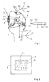
- FIG 1 very schematically shows a tibia 1 and a femur 2.
- the femur includes two condyles 3 and 4 on which is articulated the tibia.
- the destroyed ligament to replace must be located between a tibial attachment point T1 and a point F1 femoral attachment.
- T1 attachment point can be determined a priori by the surgeon from an observation, while with regard to the femoral attachment point, we only know that it must be in an area A which is a portion of the throat surface trochlean.
- One of the elements of the present invention resides in the application of such systems to the problem posed.
- a first set or triplet 10 of photoemitters 11, 12, 13 is fixed to the tibia at a point 14, for example by screwing.
- a pointer 20 provided with photoemitters 21, 22 and 23 interacting with the detection system to determine with precision any position taken by its tip 24. This pointer is used to point to point T1. It is then possible by a conventional computer system to determine the vector VT1 connecting point 14 to point T1 and therefore locating the point T1 for any position of the tibia.
- a second triplet 30 of photoemitters comprising for example three photodiodes 31, 32, 33, fixed to the femur at a point 34.
- the triplet 30 can be located by the detector system in the same way as triplet 10 and the vector VFi between point 34 and each of the points Fi can be calculated. Thus, the points Fi are located even if the femur moves.
- the present invention also provides for performing an intervention at the point F1 previously determined, this intervention being located exactly at point F1.
- the present invention provides an intervention tool, by example a drill, also carrying light emitting elements to ensure the positioning of its point of action.
- the photoemitters can be provided either on the tool itself or on a tool guide or even on an instrument visually fixing the position of the intervention point desired, for example a laser illuminating the point F1. So by example, a surgeon may first position a guide desired way then drive in a drill or from the point F1 towards the inside or from the outside of the condyle towards point F1 to create a tunnel leading to point F1. Then, as indicated above, a natural tendon or artificial can be placed in the tunnel thus formed.
- the present invention is susceptible of numerous variants and modifications which will appear to those skilled in the art.
- it can be applied as indicated previously to other areas than the positioning of a tendon tibio-femoral cross.
- we previously planned a process for selecting a point of an organ such as its distance remains invariant with respect to a point of another body movable relative to the first.
- the selected point may, in other applications, be chosen according to any other criteria.
Abstract
Description
La présente invention concerne le domaine du repérage de position d'organes de formes complexes exerçant les uns par rapport aux autres des mouvements complexes.The present invention relates to the field of tracking of position of organs of complex forms exercising one by compared to others complex movements.
Plus particulièrement, la présente invention vise pour de tels organes à repérer des points d'un organe exerçant des mouvements spécifiques par rapport à un autre organe, par exemple des points d'un organe dont la distance reste invariante lors du déplacement de cet organe par rapport à un autre.More particularly, the present invention aims to such organs to locate points of an organ exercising specific movements in relation to another organ, for example example of the points of an organ whose distance remains invariant when moving this body relative to another.
La présente invention trouve des applications dans des systèmes mécaniques complexes où il est pratiquement impossible de déterminer par le calcul le mouvement de certains organes par rapport à d'autres. Elle trouve notamment des applications dans le cas d'organes physiologiques et sera décrite ici dans le cadre d'une application concernant le domaine de la chirurgie et plus particulièrement la chirurgie orthopédique du genou.The present invention finds applications in complex mechanical systems where it is practically impossible to determine by calculation the movement of certain organs by compared to others. It finds applications in particular in the case of physiological organs and will be described here in the part of an application concerning the field of surgery and more particularly orthopedic knee surgery.
Il existe en effet des situations cliniques où il est nécessaire de relier deux organes, en tenant compte de certaines contraintes médicales. C'est en particulier le cas pour la chirurgie du genou, et plus précisément lors de la réfection d'un (des) ligament(s) croisé(s) détruit(s) par un traumatisme. There are indeed clinical situations where it is necessary to connect two bodies, taking into account certain medical constraints. This is particularly the case for surgery of the knee, and more specifically during the repair of a (cruciate ligament (s) destroyed by trauma.
Cette intervention consiste à remplacer ce(s) ligament(s) par un implant prélevé sur le patient lui-même (généralement aux dépens du tendon rotulien) ou par un ligament artificiel. Pour être efficace, cet implant doit être à la limite de la tension lors de tous les mouvements normaux (flexion-extension-rotation) du genou. S'il est trop tendu, il cassera rapidement ; s'il ne l'est pas assez, il n'interdira pas les mouvements anormaux. La contrainte médicale se traduit donc dans ce cas par une contrainte d'isométrie : le ligament doit garder une longueur constante lors de mouvements de flexion-extension.This intervention consists in replacing this (these) ligament (s) by an implant taken from the patient himself (generally at the expense of the patellar tendon) or by an artificial ligament. To be effective, this implant must be at the limit tension during all normal movements (flexion-extension-rotation) knee. If it is too tight, it will break quickly; if it is not enough, it will not ban abnormal movements. The medical constraint is therefore reflected in this case by an isometric constraint: the ligament must keep a constant length during flexion-extension movements.
Pour cela, il est nécessaire de le positionner de telle sorte que la distance entre ses points d'ancrage fémoral et tibial reste constante. Pour déterminer ces points, le chirurgien dispose de connaissances anatomo-physiologiques, qu'il peut compléter par divers dispositifs. Le point tibial est en principe facile à voir, tant en chirurgie conventionnelle qu'en arthroscopie car il est bien dégagé et car le chirurgien sait assez précisément où le placer, guidé qu'il est par le bord antérieur du toit de l'échancrure. A noter qu'il a été démontré qu'une certaine variation de son emplacement n'avait d'ailleurs que peu de conséquences sur l'isométrie du ligament. Le point fémoral est par contre très profond dans la gorge de la trochlée, aussi le chirurgien ne peut-il le déterminer visuellement qu'approximativement. Or, il a été démontré qu'une faible variation de sa position pouvait perturber considérablement l'isométrie du ligament. Aussi, pour guider le choix du point fémoral, certains ont proposé de mettre en place un ressort et de vérifier par des mouvements de flexion-extension que les points d'ancrage où est fixé ce ressort permettent de conserver l'isométrie (et donc l'iso-tension) du ressort.For this, it is necessary to position it so that the distance between its femoral anchor points and tibial remains constant. To determine these points, the surgeon has anatomo-physiological knowledge, which it can supplement with various devices. The tibial point is in principle easy to see, both in conventional surgery that in arthroscopy because it is well cleared and because the surgeon knows exactly where to place it, guided by its edge front of the roof of the notch. Note that it has been demonstrated that a certain variation in its location had that few consequences on the isometry of the ligament. Point femoral, on the other hand, is very deep in the throat of the trochlea, so the surgeon cannot determine it visually only approximately. However, it has been shown that low variation in its position could significantly disturb ligament isometry. Also, to guide the choice of point femoral, some have proposed to set up a spring and to verify by flexion-extension movements that the anchor points where this spring is fixed allow to keep the isometry (and therefore the iso-tension) of the spring.
Une fois les points d'ancrage positionnés, il faut pouvoir les viser. En effet, pour permettre une fixation solide du ligament, on l'introduit dans deux tunnels fémoral et tibial. Le tunnel tibial ne pose aucun problème de réalisation, tant en chirurgie conventionnelle qu'en arthroscopie. Le tunnel fémoral peut être réalisé de deux façons : soit de dehors en dedans, soit de dedans en dehors (tunnel borgne). Dans le premier cas (de dehors en dedans), la mèche perce la corticale externe du fémur en étant guidée par un viseur - pas toujours commode d'emploi et pas toujours aussi précis que souhaité - vers le point d'ancrage au niveau de l'échancrure inter-condylienne. La broche doit arriver exactement au point d'ancrage, toute erreur à ce niveau ayant, comme cela a été indiqué plus haut, des conséquences néfastes sur l'isométrie du ligament. Dans le deuxième cas (de dedans en dehors), la mèche attaque l'échancrure au point isométrique.Once the anchor points have been positioned, to be able to target them. Indeed, to allow a solid fixation of the ligament, we introduce it into two femoral tunnels and tibial. The tibial tunnel poses no problem of realization, both in conventional surgery and in arthroscopy. The tunnel femoral can be achieved in two ways: either from outside inside, or from inside outside (blind tunnel). In the first case (from outside to inside), the wick pierces the cortex external of the femur being guided by a viewfinder - not always convenient and not always as precise as desired - to the anchor point at the notch inter-condylar. The spindle must arrive exactly at the point anchor, any error at this level having, as has been indicated above, harmful consequences on the isometry of the ligament. In the second case (from inside to outside), the wick attacks the notch at the isometric point.
Les difficultés qui se présentent pour déterminer de façon certaine le point d'ancrage fémoral ainsi que pour être à coup sûr précis dans la technique de forage de dehors en dedans du tunnel fémoral expliquent la difficulté de cette intervention, tant en chirurgie conventionnelle qu'en arthroscopie. Or, cette intervention :
- est fréquente : plusieurs milliers de cas par an en France, ce en raison de l'importance de la gêne fonctionnelle induite par la rupture du ligament croisé antérieur, rupture fréquente car consécutive à des accidents survenant lors de la pratique de sports de masse (ski, football, hand-ball, volley ball...),
- a pour ambition de réduire le pourcentage d'évolution arthrosique de ces genoux traumatisés ; on admet qu'avec les techniques actuelles de plastie ligamentaire, 50 % de ces genoux traumatisés, opérés ou non, poseront, 25 ans après le traumatisme, le problème d'une prothèse totale de genou.
- is frequent: several thousands of cases per year in France, this due to the importance of the functional discomfort induced by the rupture of the anterior cruciate ligament, frequent rupture because consecutive to accidents occurring during the practice of mass sports (skiing , football, handball, volleyball ...),
- aims to reduce the percentage of osteoarthritis in these traumatized knees; it is admitted that with the current techniques of ligament plasty, 50% of these traumatized knees, operated or not, will pose, 25 years after the trauma, the problem of a total knee prosthesis.
La fréquence et l'enjeu de oette pathologie justifient une amélioration de la technique opératoire dont un des points passe par l'amélioration de l'isométrie du ligament implanté.The frequency and the stake of this pathology justify an improvement in the operating technique, one of the points involves improving the isometry of the implanted ligament.
De façon générale, un objet de la présente invention est de prévoir un procédé et un système de détermination d'un point invariant d'un organe mobile par rapport à un autre. In general, an object of the present invention is to provide a method and a system for determining a invariant point of a moving organ with respect to another.
Un objet plus particulier de la présente invention est de déterminer la position du point d'attache fémoral d'un ligament croisé.A more particular object of the present invention is determine the position of the femoral attachment point of a cruciate ligament.
Un autre objet de la présente invention est de prévoir un procédé d'intervention au niveau du point d'attache préalablement déterminé.Another object of the present invention is to provide an intervention process at the attachment point beforehand determined.
Pour atteindre ces objets, la présente invention prévoit un procédé de détermination de la position d'un point d'un deuxième organe mobile par rapport à un premier organe tel que la distance entre ce point du deuxième organe et un point déterminé du premier organe soit sensiblement invariante lors du déplacement du premier organe par rapport au deuxième. Ce procédé fait usage d'un système de repérage tridimensionnel de triplets d'éléments émetteurs comprenant notamment un pointeur repérable par ce système, et comprend les étapes consistant à lier un premier triplet au premier organe ; pointer avec le pointeur la position du point déterminé du premier organe et repérer cette position par rapport à celle du premier triplet ; pointer avec le pointeur les positions d'un ensemble de deuxièmes points situés dans une zone du deuxième organe où est susceptible de se trouver le point invariant ; calculer les distances entre le premier point et chacun des deuxièmes points ; déplacer le deuxième organe par rapport au premier et calculer les variations desdites distances ; et sélectionner parmi les deuxièmes points celui pour lequel ladite distance est sensiblement invariante.To achieve these objects, the present invention provides a method for determining the position of a point of a second member movable relative to a first member such that the distance between this point of the second organ and a point determined by the first organ to be substantially invariant during the displacement of the first organ relative to the second. This process makes use of a three-dimensional tracking system of triplets of transmitting elements including a pointer identifiable by this system, and includes the steps of link a first triplet to the first organ; point with the pointer the position of the determined point of the first organ and identify this position in relation to that of the first triplet; point with the pointer the positions of a set of second points located in an area of the second organ where is likely to find the invariant point; calculate distances between the first point and each of the second points; move the second organ relative to the first and calculate variations in said distances; and select from second points that for which said distance is substantially invariant.
Selon une variante de la présente invention, celle-ci comprend en outre les étapes consistant à lier un deuxième triplet au deuxième organe et à repérer les positions des deuxièmes points par rapport à ce deuxième triplet.According to a variant of the present invention, it further includes the steps of linking a second triplet to the second organ and to identify the positions of the second points compared to this second triplet.
Selon un mode de réalisation de la présente invention, celle-ci comprend en outre l'étape consistant à afficher sur un écran les projections sur un plan des deuxièmes points. According to an embodiment of the present invention, this further includes the step of displaying on a screen the projections on a plane of the second points.
Dans une application de la présente invention, le premier organe est un tibia et le deuxième organe est un fémur, le point déterminé du tibia étant un premier point d'attache d'un ligament croisé du genou et le point invariant du deuxième organe étant le point d'attache fémoral de ce ligament croisé.In an application of the present invention, the first organ is a tibia and the second organ is a femur, the determined point of the tibia being a first point of attachment of a cruciate ligament of the knee and the invariant point of the second organ being the femoral attachment point of this cruciate ligament.
Selon un mode de réalisation de la présente invention, le système de repérage tridimensionnel est un système à photodiodes et caméras.According to an embodiment of the present invention, the three-dimensional tracking system is a photodiode system and cameras.
Dans une application, le procédé selon l'invention est utilisé pour le positionnement d'un outil sur le point invariant, l'outil ou un support de guidage de cet outil est muni d'un triplet d'éléments émetteurs et l'outil ou son support est positionné pour que le point d'action de l'outil passe par le point invariant. L'outil est par exemple une perceuse.In one application, the method according to the invention is used for positioning a tool on the invariant point, the tool or a guide support for this tool is provided of a triplet of emitting elements and the tool or its support is positioned so that the tool's action point passes through the invariant point. The tool is for example a drill.
L'invention prévoit aussi un système de mise en oeuvre du procédé ci-dessus.The invention also provides an implementation system of the above process.
Ces objets, caractéristiques et avantages ainsi que
d'autres de la présente invention seront exposés en détail dans
la description suivante d'un mode de réalisation particulier
faite en relation avec les figures jointes parmi lesquelles :
La présente invention sera exposée plus particulièrement dans le cadre de la détermination du point d'attache fémoral d'un ligament croisé de genou.The present invention will be explained more particularly as part of the determination of the attachment point femoral cruciate ligament of the knee.
La figure 1 représente très schématiquement un tibia 1
et un fémur 2. Le fémur comprend deux condyles 3 et 4 sur lesquels
est articulé le tibia. Le ligament détruit à remplacer
doit être situé entre un point d'attache tibial T1 et un point
d'attache fémoral F1. Comme on l'a indiqué précédemment, le
point d'attache T1 peut être déterminé a priori par le chirurgien
à partir d'une observation, tandis qu'en ce qui concerne le
point d'attache fémoral, on sait seulement qu'il doit se trouver
dans une zone A qui est une portion de la surface de la gorge
trochléenne.Figure 1 very schematically shows a tibia 1
and a femur 2. The femur includes two
On connaít des systèmes de repérage de la position
d'émetteurs tels que des émetteurs optiques ou infrarouges, mais
qui pourraient aussi être des émetteurs de rayonnement à
d'autres longueurs d'onde qui utilisent des ensembles de
capteurs et déterminent la position de chacun des émetteurs par
triangulation. Un exemple d'une telle installation appliquée à
la détermination de la position de la tête est décrit dans
l'article du journal Innovation et Technologie en Biologie et
Médecine (ITBM), volume 13, N° 4, 1992, L. Adams et al. page
410-424. Il existe également des systèmes commercialisés sous la
marque "Optotrak" par la société dite Northern Digital.We know position tracking systems
transmitters such as optical or infrared transmitters, but
which could also be emitters of radiation to
other wavelengths that use sets of
sensors and determine the position of each of the transmitters by
triangulation. An example of such an installation applied to
determining the position of the head is described in
the article in the journal Innovation et Technologie en Biologie et
Medicine (ITBM),
L'un des éléments de la présente invention réside dans l'application de tels systèmes au problème posé.One of the elements of the present invention resides in the application of such systems to the problem posed.
Ainsi, le patient est disposé dans un environnement
comprenant des caméras propres à détecter les positions de
photoémetteurs. Un premier ensemble ou triplet 10 de photoémetteurs
11, 12, 13 est fixé au tibia en un point 14, par exemple
par vissage. Un pointeur 20 muni de photoémetteurs 21, 22 et 23
interagissant avec le système de détection permet de déterminer
avec précision toute position prise par sa pointe 24. Ce pointeur
est utilisé pour pointer le point T1. Il est alors possible
par un système informatique classique de déterminer le vecteur
VT1 reliant le point 14 au point T1 et donc de localiser le
point T1 pour toute position du tibia.So the patient is arranged in an environment
including cameras capable of detecting the positions of
photoemitters. A first set or
On utilise ensuite à nouveau le pointeur 20 pour
déterminer les coordonnées d'une série de points disposés dans
la zone A de la surface de la gorge trochléenne dans laquelle
est susceptible de se trouver le point d'attache fémoral recherché
F1 et on mémorise la position d'une succession de points Fi
pointés. We then use the
Pour simplifier la tâche de celui qui réalise l'analyse, il est possible, par des moyens connus associés aux systèmes de localisation spatiale susmentionnés, et comme cela est représenté en figure 2, d'afficher sur un écran E la localisation d'une projection des points Fi sur un plan. Ceci permet en particulier de déterminer si l'on a bien analysé toute la surface que l'on souhaitait pointer. Par exemple, si on a pointé une série de points Fi indiqués par des ronds en figure 2, on s'apercevra facilement sur l'écran qu'il serait souhaitable de pointer des points supplémentaires, marqués dans la figure par des croix, pour réaliser une analyse régulière de la surface A.To simplify the task of the performer, it is possible, by known means associated with above-mentioned spatial location systems, and like that is shown in Figure 2, to display on a screen E the location of a projection of the points Fi on a plane. this allows in particular to determine whether we have analyzed all of the surface that we wanted to point to. For example, if we pointed a series of points Fi indicated by circles in FIG. 2, we will easily see on the screen that it would be desirable to point additional points, marked in the figure by crosses, to perform a regular analysis of surface A.
Par un traitement informatique classique, on calcule les distances Di entre le point T1 et chacun des points Fi. Ces distances sont mémorisées. Des programmes pour effectuer ces calculs et ceux mentionnés ci-après peuvent être réalisés pour tout spécialiste de la programmation qui pourra, par exemple, s'inspirer de l'article de P. Cinquin et al, "IGOR : Image Guided Operating Robot", ITBM, Vol. 13, N° 4, 1992.By conventional computer processing, we calculate the distances Di between the point T1 and each of the points Fi. These distances are stored. Programs to perform these calculations and those mentioned below can be performed for any programming specialist who can, for example, take inspiration from the article by P. Cinquin et al, "IGOR: Image Guided Operating Robot ", ITBM, Vol. 13, No. 4, 1992.
Ensuite, le fémur restant fixe, on fait parcourir au
tibia son trajet normal de flexion-extension tout en détectant
les variations de position résultantes du triplet 10 et corrélativement
du point T1. Simultanément ou ultérieurement, selon les
capacités du système de traitement, on calcule les variations de
chacune des distances Di entre le point T1 et chacun des points
Fi et on sélectionne comme point d'attache fémoral le point F1
parmi les points Fi pour lequel la variation de distance Di a
été minimale au cours de ce déplacement.Then, the femur remaining fixed, we run through the
shin its normal flexion-extension path while detecting
the resulting position variations of
Dans ce qui précède, on a supposé que le fémur restait
fixe. Pour s'affranchir de oette contrainte, selon un mode de
réalisation préféré, il est prévu un deuxième triplet 30 de
photoémetteurs, comprenant par exemple trois photodiodes 31, 32,
33, fixé au fémur en un point 34. Le triplet 30 peut être localisé
par le système détecteur de la même façon que le triplet 10
et le vecteur VFi entre le point 34 et chacun des points Fi peut
être calculé. Ainsi, les points Fi sont localisés même si le
fémur se déplace.In the above, it was assumed that the femur remained
fixed. To get rid of this constraint, according to a mode of
preferred embodiment, a
La présente invention prévoit également d'effectuer une intervention au niveau du point F1 précédemment déterminé, cette intervention étant exactement située au point F1. Pour cela, la présente invention prévoit un outil d'intervention, par exemple une perceuse, portant lui aussi des éléments photoémetteurs pour assurer le positionnement de son point d'action. Les photoémetteurs pourront être prévus ou bien sur l'outil lui-même ou bien sur un guide porte-outil ou bien encore sur un instrument fixant visuellement la position du point d'intervention souhaité, par exemple un laser éclairant le point F1. Ainsi, par exemple, un chirurgien pourra d'abord positionner un guide de façon souhaitée puis enfoncer une perceuse ou bien à partir du point F1 vers l'intérieur ou bien de l'extérieur du condyle vers le point F1 pour ménager un tunnel débouchant au point F1. Ensuite, de la façon indiquée précédemment, un tendon naturel ou artificiel pourra être mis en place dans le tunnel ainsi formé.The present invention also provides for performing an intervention at the point F1 previously determined, this intervention being located exactly at point F1. For this, the present invention provides an intervention tool, by example a drill, also carrying light emitting elements to ensure the positioning of its point of action. The photoemitters can be provided either on the tool itself or on a tool guide or even on an instrument visually fixing the position of the intervention point desired, for example a laser illuminating the point F1. So by example, a surgeon may first position a guide desired way then drive in a drill or from the point F1 towards the inside or from the outside of the condyle towards point F1 to create a tunnel leading to point F1. Then, as indicated above, a natural tendon or artificial can be placed in the tunnel thus formed.
La présente invention est susceptible de nombreuses variantes et modifications qui apparaítront à l'homme de l'art. Notamment, elle pourra être appliquée comme cela a été indiqué précédemment à d'autres domaines qu'au positionnement d'un tendon croisé tibio-fémoral. Egalement, on a prévu précédemment un procédé permettant de sélectionner un point d'un organe tel que sa distance reste invariante par rapport à un point d'un autre organe mobile par rapport au premier. Le point sélectionné pourra, dans d'autres applications, être choisi en fonction de tout autre critère. On pourra par exemple inversement choisir un point présentant un déplacement maximal par rapport à un autre ou encore un point présentant un déplacement par rapport à un autre conforme à une fonction souhaitée.The present invention is susceptible of numerous variants and modifications which will appear to those skilled in the art. In particular, it can be applied as indicated previously to other areas than the positioning of a tendon tibio-femoral cross. Also, we previously planned a process for selecting a point of an organ such as its distance remains invariant with respect to a point of another body movable relative to the first. The selected point may, in other applications, be chosen according to any other criteria. We could, for example, inversely choose a point with maximum displacement relative to another or a point with displacement relative to a other according to a desired function.
Claims (9)
- A method for determining the position of a point of a second organ movable with respect to a first organ, such that the distance separating said point of the second organ from a predetermined point of the first organ is substantially invariant during the movement of the first organ with respect to the second organ, said method using a three-dimensional locating system including triplets of emitting elements especially including a pointer that can be located by said system, characterized in that it includes the following steps:linking a first triplet (14) to the first organ;pointing with the pointer (20) at the position of the predetermined point (T1) of the first organ and locating this position with respect to the position of the first triplet;pointing with the pointer at the positions of an assembly of second points (Fi) that are positioned within an area (A) of the second organ where the invariant point is likely to be found;calculating the distances (Di) separating the first point from each of the second points;moving the second organ with respect to the first organ and calculating the variations in said distances; andselecting amongst second points the point (F1) for which said distance is substantially invariant.
- The method of claim 1, characterized in that it further includes the steps consisting in linking a second triplet (30) to the second organ and locating the positions of the second points with respect to said second triplet.
- The method of claim 1, characterized in that it includes the step consisting in displaying on a screen (E) the projections of the second points on a plane.
- The method of any of claims 1 to 3, characterized in that the first organ is a tibia (1) and the second organ is a femur (2), the determined tibial point (T1) being a first fixation point of a crossed ligament of the knee, and the invariant point (F1) of the second organ being the femoral fixation point of said crossed ligament.
- The method of claim 1, characterized in that said three-dimensional locating system is a system including photodiodes and cameras.
- Application of the method according to any of claims 1 to 5 to the positioning of a tool at the invariant point, characterized in that the tool or a guiding support of said tool is provided with a triplet of emitting elements and wherein the tool or its support is positioned so that the operating point of the tool passes through the invariant point.
- Application of the method according to claims 4 and 6 to a drilling through the invariant point of the second set of points, characterized in that it consists in providing a guiding support of a drilling tool with a triplet of emitting elements and in positioning said support so that the axis of the drilling passes through the invariant point.
- A system for determining the position of a point of a second organ movable with respect to a first organ such that the distance between said point of the second organ and a determined point of the first organ follows a predetermined law during the displacement of the first organ with respect to the second organ, said system including three-dimensional locating means including triplets of emitting elements and a pointer, characterized in that it includes:a first triplet (14) fixed to the first organ;a pointer (20) to point at the position of the determined point (T1) of the first organ and at the positions of an assembly of second points (Fi) that are located within the area of the second organ where the desired point is likely to be found; andmeans for calculating the position of the determined point with respect to the position of the first triplet, distances (Di) between the first point and each of the second points, and variations of said distances when the second organ moves with respect to the first organ;
whereby it is possible to select amongst second points the point (F1) for which said distance follows said predetermined law. - The system of claim 8, characterized in that it further includes a second triplet (30) associated with the second organ and means for calculating the positions of the second points with respect to said second triplet.
Applications Claiming Priority (2)
| Application Number | Priority Date | Filing Date | Title |
|---|---|---|---|
| FR9215549 | 1992-12-15 | ||
| FR9215549A FR2699271B1 (en) | 1992-12-15 | 1992-12-15 | Method for determining the femoral anchor point of a cruciate knee ligament. |
Publications (2)
| Publication Number | Publication Date |
|---|---|
| EP0603089A1 EP0603089A1 (en) | 1994-06-22 |
| EP0603089B1 true EP0603089B1 (en) | 1998-06-17 |
Family
ID=9436979
Family Applications (1)
| Application Number | Title | Priority Date | Filing Date |
|---|---|---|---|
| EP93420497A Expired - Lifetime EP0603089B1 (en) | 1992-12-15 | 1993-12-13 | Procedure for determining the femoral anchorage part of a cruciate knee ligament |
Country Status (7)
| Country | Link |
|---|---|
| US (1) | US5564437A (en) |
| EP (1) | EP0603089B1 (en) |
| JP (1) | JPH07415A (en) |
| AT (1) | ATE167380T1 (en) |
| DE (1) | DE69319212T2 (en) |
| ES (1) | ES2119879T3 (en) |
| FR (1) | FR2699271B1 (en) |
Cited By (5)
| Publication number | Priority date | Publication date | Assignee | Title |
|---|---|---|---|---|
| US6236875B1 (en) | 1994-10-07 | 2001-05-22 | Surgical Navigation Technologies | Surgical navigation systems including reference and localization frames |
| US6347240B1 (en) | 1990-10-19 | 2002-02-12 | St. Louis University | System and method for use in displaying images of a body part |
| US6491702B2 (en) | 1992-04-21 | 2002-12-10 | Sofamor Danek Holdings, Inc. | Apparatus and method for photogrammetric surgical localization |
| US6725082B2 (en) | 1999-03-17 | 2004-04-20 | Synthes U.S.A. | System and method for ligament graft placement |
| US8046053B2 (en) | 1994-10-07 | 2011-10-25 | Foley Kevin T | System and method for modifying images of a body part |
Families Citing this family (62)
| Publication number | Priority date | Publication date | Assignee | Title |
|---|---|---|---|---|
| JP2617965B2 (en) * | 1988-01-20 | 1997-06-11 | オリンパス光学工業株式会社 | Viewfinder optical system for single-lens reflex camera |
| US5571083A (en) * | 1994-02-18 | 1996-11-05 | Lemelson; Jerome H. | Method and system for cell transplantation |
| DE4446934C1 (en) * | 1994-12-28 | 1996-07-04 | Basim A Dr Med Fleega | Medicinal rule for transarthroscopic operations |
| US5806518A (en) * | 1995-09-11 | 1998-09-15 | Integrated Surgical Systems | Method and system for positioning surgical robot |
| US8480754B2 (en) | 2001-05-25 | 2013-07-09 | Conformis, Inc. | Patient-adapted and improved articular implants, designs and related guide tools |
| US8882847B2 (en) | 2001-05-25 | 2014-11-11 | Conformis, Inc. | Patient selectable knee joint arthroplasty devices |
| US8735773B2 (en) | 2007-02-14 | 2014-05-27 | Conformis, Inc. | Implant device and method for manufacture |
| US8556983B2 (en) | 2001-05-25 | 2013-10-15 | Conformis, Inc. | Patient-adapted and improved orthopedic implants, designs and related tools |
| US8545569B2 (en) | 2001-05-25 | 2013-10-01 | Conformis, Inc. | Patient selectable knee arthroplasty devices |
| US9603711B2 (en) | 2001-05-25 | 2017-03-28 | Conformis, Inc. | Patient-adapted and improved articular implants, designs and related guide tools |
| US20040133276A1 (en) | 2002-10-07 | 2004-07-08 | Imaging Therapeutics, Inc. | Minimally invasive joint implant with 3-Dimensional geometry matching the articular surfaces |
| US7468075B2 (en) | 2001-05-25 | 2008-12-23 | Conformis, Inc. | Methods and compositions for articular repair |
| US8771365B2 (en) | 2009-02-25 | 2014-07-08 | Conformis, Inc. | Patient-adapted and improved orthopedic implants, designs, and related tools |
| DE29704393U1 (en) * | 1997-03-11 | 1997-07-17 | Aesculap Ag | Device for preoperative determination of the position data of endoprosthesis parts |
| DE19747427C2 (en) * | 1997-10-28 | 1999-12-09 | Zeiss Carl Fa | Device for bone segment navigation |
| WO1999023956A1 (en) * | 1997-11-05 | 1999-05-20 | Synthes Ag, Chur | Virtual representation of a bone or a bone joint |
| US6021343A (en) * | 1997-11-20 | 2000-02-01 | Surgical Navigation Technologies | Image guided awl/tap/screwdriver |
| ES2228043T3 (en) * | 1998-05-28 | 2005-04-01 | Orthosoft, Inc. | INTERACTIVE SURGICAL SYSTEM ASSISTED BY COMPUTER. |
| US6033415A (en) * | 1998-09-14 | 2000-03-07 | Integrated Surgical Systems | System and method for performing image directed robotic orthopaedic procedures without a fiducial reference system |
| US7239908B1 (en) | 1998-09-14 | 2007-07-03 | The Board Of Trustees Of The Leland Stanford Junior University | Assessing the condition of a joint and devising treatment |
| JP2002532126A (en) | 1998-09-14 | 2002-10-02 | スタンフォード ユニバーシティ | Joint condition evaluation and damage prevention device |
| FR2785517B1 (en) * | 1998-11-10 | 2001-03-09 | Univ Joseph Fourier | METHOD AND DEVICE FOR DETERMINING THE CENTER OF A JOINT |
| US6430434B1 (en) | 1998-12-14 | 2002-08-06 | Integrated Surgical Systems, Inc. | Method for determining the location and orientation of a bone for computer-assisted orthopedic procedures using intraoperatively attached markers |
| US6322567B1 (en) | 1998-12-14 | 2001-11-27 | Integrated Surgical Systems, Inc. | Bone motion tracking system |
| AU3357400A (en) * | 1999-02-16 | 2000-09-04 | Frederic Picard | Optimizing alignment of an appendicular |
| WO2002022014A1 (en) | 2000-09-14 | 2002-03-21 | The Board Of Trustees Of The Leland Stanford Junior University | Assessing the condition of a joint and devising treatment |
| WO2002023483A2 (en) | 2000-09-14 | 2002-03-21 | Leland Stanford Junior University | Technique for manipulating medical images |
| CA2425089A1 (en) | 2000-09-14 | 2002-03-21 | Philipp Lang | Assessing condition of a joint and cartilage loss |
| FR2816200A1 (en) * | 2000-11-06 | 2002-05-10 | Praxim | DETERMINING THE POSITION OF A KNEE PROSTHESIS |
| WO2002096268A2 (en) | 2001-05-25 | 2002-12-05 | Imaging Therapeutics, Inc. | Methods and compositions for articular resurfacing |
| AU2003201572A1 (en) * | 2002-01-16 | 2003-09-02 | Orthosoft Inc. | Method and apparatus for reconstructing bone surfaces during surgery |
| US7715602B2 (en) * | 2002-01-18 | 2010-05-11 | Orthosoft Inc. | Method and apparatus for reconstructing bone surfaces during surgery |
| US7166114B2 (en) * | 2002-09-18 | 2007-01-23 | Stryker Leibinger Gmbh & Co Kg | Method and system for calibrating a surgical tool and adapter thereof |
| WO2004032780A1 (en) * | 2002-09-27 | 2004-04-22 | Aesculap Ag & Co. Kg | Method and device for determining the position of the tibial protrusion point of the anterior cruciate ligament |
| EP3075356B1 (en) | 2002-11-07 | 2023-07-05 | ConforMIS, Inc. | Method of selecting a meniscal implant |
| US7319897B2 (en) * | 2002-12-02 | 2008-01-15 | Aesculap Ag & Co. Kg | Localization device display method and apparatus |
| US7209776B2 (en) * | 2002-12-03 | 2007-04-24 | Aesculap Ag & Co. Kg | Method of determining the position of the articular point of a joint |
| US7427272B2 (en) * | 2003-07-15 | 2008-09-23 | Orthosoft Inc. | Method for locating the mechanical axis of a femur |
| US7905924B2 (en) * | 2003-09-03 | 2011-03-15 | Ralph Richard White | Extracapsular surgical procedure |
| US7873400B2 (en) * | 2003-12-10 | 2011-01-18 | Stryker Leibinger Gmbh & Co. Kg. | Adapter for surgical navigation trackers |
| US7771436B2 (en) * | 2003-12-10 | 2010-08-10 | Stryker Leibinger Gmbh & Co. Kg. | Surgical navigation tracker, system and method |
| US20060036397A1 (en) * | 2004-03-24 | 2006-02-16 | Robert Dick | Method and device for ascertaining a position of a characteristic point |
| EP1579803A1 (en) * | 2004-03-24 | 2005-09-28 | BrainLAB AG | Method and device for detecting the position of a characteristic point |
| US7623250B2 (en) * | 2005-02-04 | 2009-11-24 | Stryker Leibinger Gmbh & Co. Kg. | Enhanced shape characterization device and method |
| US20070239169A1 (en) * | 2006-03-17 | 2007-10-11 | Perception Raisonnement Action En Medecine | Reference marker and use in a motion tracking system |
| US8337508B2 (en) | 2006-03-20 | 2012-12-25 | Perception Raisonnement Action En Medecine | Distractor system |
| US7949386B2 (en) | 2006-03-21 | 2011-05-24 | A2 Surgical | Computer-aided osteoplasty surgery system |
| US8214016B2 (en) | 2006-12-12 | 2012-07-03 | Perception Raisonnement Action En Medecine | System and method for determining an optimal type and position of an implant |
| EP2591756A1 (en) | 2007-02-14 | 2013-05-15 | Conformis, Inc. | Implant device and method for manufacture |
| US7678147B2 (en) * | 2007-05-01 | 2010-03-16 | Moximed, Inc. | Extra-articular implantable mechanical energy absorbing systems and implantation method |
| US8894714B2 (en) | 2007-05-01 | 2014-11-25 | Moximed, Inc. | Unlinked implantable knee unloading device |
| EP2194836B1 (en) * | 2007-09-25 | 2015-11-04 | Perception Raisonnement Action En Medecine | Apparatus for assisting cartilage diagnostic and therapeutic procedures |
| DE502008002604D1 (en) | 2008-02-21 | 2011-03-31 | Brainlab Ag | Position calculation of body parts taking into account the anatomical symmetry |
| WO2009111626A2 (en) | 2008-03-05 | 2009-09-11 | Conformis, Inc. | Implants for altering wear patterns of articular surfaces |
| JP2011519713A (en) | 2008-05-12 | 2011-07-14 | コンフォーミス・インコーポレイテッド | Devices and methods for treatment of facet joints and other joints |
| WO2010099231A2 (en) | 2009-02-24 | 2010-09-02 | Conformis, Inc. | Automated systems for manufacturing patient-specific orthopedic implants and instrumentation |
| AU2010327987B2 (en) | 2009-12-11 | 2015-04-02 | Conformis, Inc. | Patient-specific and patient-engineered orthopedic implants |
| JP2013523415A (en) | 2010-04-14 | 2013-06-17 | スミス アンド ネフュー インコーポレーテッド | System and method for patient-assisted computer-assisted surgical procedure |
| CN103476363B (en) | 2011-02-15 | 2017-06-30 | 康复米斯公司 | Operation and the instrument of change and/or asymmetry are dissected in improved suitable patient's type joint implant and treatment, assessment, correction, modification and/or adaptation |
| US9289264B2 (en) * | 2011-12-29 | 2016-03-22 | Mako Surgical Corp. | Systems and methods for guiding an instrument using haptic object with collapsing geometry |
| US9639156B2 (en) | 2011-12-29 | 2017-05-02 | Mako Surgical Corp. | Systems and methods for selectively activating haptic guide zones |
| KR101705199B1 (en) * | 2015-05-12 | 2017-02-09 | 주식회사 코어라인소프트 | System and method for simulation of repair operation of anterior cruciate ligament using medical images |
Family Cites Families (6)
| Publication number | Priority date | Publication date | Assignee | Title |
|---|---|---|---|---|
| CH671873A5 (en) * | 1985-10-03 | 1989-10-13 | Synthes Ag | |
| US4712542A (en) * | 1986-06-30 | 1987-12-15 | Medmetric Corporation | System for establishing ligament graft orientation and isometry |
| US5037426A (en) * | 1988-09-19 | 1991-08-06 | Marlowe Goble E | Procedure for verifying isometric ligament positioning |
| US4964862A (en) * | 1989-08-31 | 1990-10-23 | Micro Strain Company | Method of and means for measuring ligament tension |
| DE9005819U1 (en) * | 1990-05-22 | 1990-07-26 | Aesculap Ag, 7200 Tuttlingen, De | |
| US5230623A (en) * | 1991-12-10 | 1993-07-27 | Radionics, Inc. | Operating pointer with interactive computergraphics |
-
1992
- 1992-12-15 FR FR9215549A patent/FR2699271B1/en not_active Expired - Fee Related
-
1993
- 1993-12-13 EP EP93420497A patent/EP0603089B1/en not_active Expired - Lifetime
- 1993-12-13 DE DE69319212T patent/DE69319212T2/en not_active Expired - Lifetime
- 1993-12-13 ES ES93420497T patent/ES2119879T3/en not_active Expired - Lifetime
- 1993-12-13 AT AT93420497T patent/ATE167380T1/en active
- 1993-12-14 US US08/166,032 patent/US5564437A/en not_active Expired - Lifetime
- 1993-12-15 JP JP5342219A patent/JPH07415A/en not_active Withdrawn
Cited By (7)
| Publication number | Priority date | Publication date | Assignee | Title |
|---|---|---|---|---|
| US6347240B1 (en) | 1990-10-19 | 2002-02-12 | St. Louis University | System and method for use in displaying images of a body part |
| US6434415B1 (en) | 1990-10-19 | 2002-08-13 | St. Louis University | System for use in displaying images of a body part |
| US6490467B1 (en) | 1990-10-19 | 2002-12-03 | Surgical Navigation Technologies, Inc. | Surgical navigation systems including reference and localization frames |
| US6491702B2 (en) | 1992-04-21 | 2002-12-10 | Sofamor Danek Holdings, Inc. | Apparatus and method for photogrammetric surgical localization |
| US6236875B1 (en) | 1994-10-07 | 2001-05-22 | Surgical Navigation Technologies | Surgical navigation systems including reference and localization frames |
| US8046053B2 (en) | 1994-10-07 | 2011-10-25 | Foley Kevin T | System and method for modifying images of a body part |
| US6725082B2 (en) | 1999-03-17 | 2004-04-20 | Synthes U.S.A. | System and method for ligament graft placement |
Also Published As
| Publication number | Publication date |
|---|---|
| ES2119879T3 (en) | 1998-10-16 |
| EP0603089A1 (en) | 1994-06-22 |
| ATE167380T1 (en) | 1998-07-15 |
| DE69319212T2 (en) | 1998-11-19 |
| US5564437A (en) | 1996-10-15 |
| FR2699271B1 (en) | 1995-03-17 |
| DE69319212D1 (en) | 1998-07-23 |
| JPH07415A (en) | 1995-01-06 |
| FR2699271A1 (en) | 1994-06-17 |
Similar Documents
| Publication | Publication Date | Title |
|---|---|---|
| EP0603089B1 (en) | Procedure for determining the femoral anchorage part of a cruciate knee ligament | |
| EP1341468A1 (en) | System for determining the position of a knee prosthesis | |
| US11617492B2 (en) | Medical three-dimensional (3D) scanning and mapping system | |
| EP0187283B1 (en) | Device to locate in situ through-holes in a hollow pin that is implanted into the medullary canal for the retention of the fragments of a fractured bone | |
| EP1712192A1 (en) | Surgical device for implanting a partial or total knee prosthesis | |
| EP1732448B1 (en) | Ancillary assembly for implanting a knee prosthesis | |
| US20200100916A1 (en) | Method of using a measuring instrument in an orthopaedic surgical procedure | |
| JP2001522630A (en) | Virtual display of bone or bone joint | |
| FR2831794A1 (en) | METHOD FOR SELECTING KNEE PROSTHESIS ELEMENTS AND DEVICE FOR IMPLEMENTING SAME | |
| FR2918554A1 (en) | Adjustable drilling jig for drilling posterolateral beam inserting femoral tunnel, has plate whose axis is inclined with respect to arm plane, so that axis of plate is coincidence with large axis of insertion zone in lateral condyle of knee | |
| EP0733338A1 (en) | Device for measuring the position of the fixation point of an eye on a screen | |
| EP1059061A3 (en) | Method and apparatus for measurement of the refractive properties of the human eye | |
| EP1083840A1 (en) | Mapping method and device for robotic surgery | |
| AU2005200970A1 (en) | Navigated stemmed orthopaedic implant inserter | |
| FR3052654A1 (en) | METHOD FOR ESTIMATING RELATIVE ORIENTATION BETWEEN TIBIA AND FEMUR | |
| FR3030222A1 (en) | SURGICAL ORIENTATION SYSTEM | |
| EP4230168A1 (en) | Robotic spinal surgery system | |
| US11944393B2 (en) | Patella tracking | |
| FR2882248A1 (en) | PORCEDE AND SYSTEM FOR ASSISTING THE GUIDANCE OF A TOOL FOR MEDICAL USE | |
| FR2801185A1 (en) | SECURE VIDEO ENDOSCOPE WITH INTEGRATED LASER PROFILOMETER FOR COMPUTER-ASSISTED SURGERY | |
| FR3078624A1 (en) | SYSTEM AND METHOD FOR ASSISTING REALITY INCREASED IN POSITIONING OF A PATIENT-SPECIFIC SURGICAL INSTRUMENTATION | |
| EP4069130A1 (en) | Augmented reality guidance system for guiding surgical operations on an articulating portion of a bone | |
| EP0868886A1 (en) | Method and device for marking and localizing a treatment zone in an organism | |
| EP3880087A1 (en) | Cutting device for the placement of a knee prosthesis | |
| FR2838627A1 (en) | Ancillary for orthopedic surgery navigation system comprises part for fixing to limb and second part comprising positioning guide for surgical instrument having three markers, parts connected by ball joint |
Legal Events
| Date | Code | Title | Description |
|---|---|---|---|
| PUAI | Public reference made under article 153(3) epc to a published international application that has entered the european phase |
Free format text: ORIGINAL CODE: 0009012 |
|
| AK | Designated contracting states |
Kind code of ref document: A1 Designated state(s): AT BE CH DE ES FR GB IT LI NL |
|
| 17P | Request for examination filed |
Effective date: 19941130 |
|
| GRAG | Despatch of communication of intention to grant |
Free format text: ORIGINAL CODE: EPIDOS AGRA |
|
| 17Q | First examination report despatched |
Effective date: 19970821 |
|
| GRAG | Despatch of communication of intention to grant |
Free format text: ORIGINAL CODE: EPIDOS AGRA |
|
| GRAH | Despatch of communication of intention to grant a patent |
Free format text: ORIGINAL CODE: EPIDOS IGRA |
|
| GRAH | Despatch of communication of intention to grant a patent |
Free format text: ORIGINAL CODE: EPIDOS IGRA |
|
| GRAA | (expected) grant |
Free format text: ORIGINAL CODE: 0009210 |
|
| AK | Designated contracting states |
Kind code of ref document: B1 Designated state(s): AT BE CH DE ES FR GB IT LI NL |
|
| REF | Corresponds to: |
Ref document number: 167380 Country of ref document: AT Date of ref document: 19980715 Kind code of ref document: T |
|
| RIN1 | Information on inventor provided before grant (corrected) |
Inventor name: CHAMPLEBAUX, GUILLAUME Inventor name: LAVALLEE, STEPHANE Inventor name: TROCCAZ, JOCELYNE Inventor name: JULLIARD, REMI Inventor name: CINQUIN, PHILIPPE Inventor name: BAINVILLE, ERIC |
|
| REG | Reference to a national code |
Ref country code: CH Ref legal event code: EP |
|
| REF | Corresponds to: |
Ref document number: 69319212 Country of ref document: DE Date of ref document: 19980723 |
|
| GBT | Gb: translation of ep patent filed (gb section 77(6)(a)/1977) |
Effective date: 19980804 |
|
| REG | Reference to a national code |
Ref country code: CH Ref legal event code: NV Representative=s name: MOINAS SAVOYE & CRONIN |
|
| REG | Reference to a national code |
Ref country code: ES Ref legal event code: FG2A Ref document number: 2119879 Country of ref document: ES Kind code of ref document: T3 |
|
| PLBE | No opposition filed within time limit |
Free format text: ORIGINAL CODE: 0009261 |
|
| STAA | Information on the status of an ep patent application or granted ep patent |
Free format text: STATUS: NO OPPOSITION FILED WITHIN TIME LIMIT |
|
| 26N | No opposition filed | ||
| REG | Reference to a national code |
Ref country code: GB Ref legal event code: IF02 |
|
| PGFP | Annual fee paid to national office [announced via postgrant information from national office to epo] |
Ref country code: DE Payment date: 20121207 Year of fee payment: 20 Ref country code: CH Payment date: 20121211 Year of fee payment: 20 |
|
| PGFP | Annual fee paid to national office [announced via postgrant information from national office to epo] |
Ref country code: ES Payment date: 20121219 Year of fee payment: 20 Ref country code: IT Payment date: 20121217 Year of fee payment: 20 Ref country code: GB Payment date: 20121219 Year of fee payment: 20 |
|
| PGFP | Annual fee paid to national office [announced via postgrant information from national office to epo] |
Ref country code: AT Payment date: 20121123 Year of fee payment: 20 Ref country code: NL Payment date: 20121122 Year of fee payment: 20 |
|
| PGFP | Annual fee paid to national office [announced via postgrant information from national office to epo] |
Ref country code: FR Payment date: 20130129 Year of fee payment: 20 Ref country code: BE Payment date: 20121219 Year of fee payment: 20 |
|
| REG | Reference to a national code |
Ref country code: DE Ref legal event code: R071 Ref document number: 69319212 Country of ref document: DE |
|
| REG | Reference to a national code |
Ref country code: NL Ref legal event code: V4 Effective date: 20131213 |
|
| BE20 | Be: patent expired |
Owner name: UNIVERSITE JOSEPH *FOURIER Effective date: 20131213 |
|
| REG | Reference to a national code |
Ref country code: CH Ref legal event code: PL |
|
| REG | Reference to a national code |
Ref country code: GB Ref legal event code: PE20 Expiry date: 20131212 |
|
| PG25 | Lapsed in a contracting state [announced via postgrant information from national office to epo] |
Ref country code: DE Free format text: LAPSE BECAUSE OF EXPIRATION OF PROTECTION Effective date: 20131214 Ref country code: GB Free format text: LAPSE BECAUSE OF EXPIRATION OF PROTECTION Effective date: 20131212 |
|
| REG | Reference to a national code |
Ref country code: AT Ref legal event code: MK07 Ref document number: 167380 Country of ref document: AT Kind code of ref document: T Effective date: 20131213 |
|
| REG | Reference to a national code |
Ref country code: ES Ref legal event code: FD2A Effective date: 20140925 |
|
| PG25 | Lapsed in a contracting state [announced via postgrant information from national office to epo] |
Ref country code: ES Free format text: LAPSE BECAUSE OF EXPIRATION OF PROTECTION Effective date: 20131214 |