EP0604864A2 - Traction control system and valve therefor - Google Patents
Traction control system and valve therefor Download PDFInfo
- Publication number
- EP0604864A2 EP0604864A2 EP93120482A EP93120482A EP0604864A2 EP 0604864 A2 EP0604864 A2 EP 0604864A2 EP 93120482 A EP93120482 A EP 93120482A EP 93120482 A EP93120482 A EP 93120482A EP 0604864 A2 EP0604864 A2 EP 0604864A2
- Authority
- EP
- European Patent Office
- Prior art keywords
- valve
- air
- brake
- pressure
- during
- Prior art date
- Legal status (The legal status is an assumption and is not a legal conclusion. Google has not performed a legal analysis and makes no representation as to the accuracy of the status listed.)
- Withdrawn
Links
Images


Classifications
-
- B—PERFORMING OPERATIONS; TRANSPORTING
- B60—VEHICLES IN GENERAL
- B60T—VEHICLE BRAKE CONTROL SYSTEMS OR PARTS THEREOF; BRAKE CONTROL SYSTEMS OR PARTS THEREOF, IN GENERAL; ARRANGEMENT OF BRAKING ELEMENTS ON VEHICLES IN GENERAL; PORTABLE DEVICES FOR PREVENTING UNWANTED MOVEMENT OF VEHICLES; VEHICLE MODIFICATIONS TO FACILITATE COOLING OF BRAKES
- B60T8/00—Arrangements for adjusting wheel-braking force to meet varying vehicular or ground-surface conditions, e.g. limiting or varying distribution of braking force
- B60T8/32—Arrangements for adjusting wheel-braking force to meet varying vehicular or ground-surface conditions, e.g. limiting or varying distribution of braking force responsive to a speed condition, e.g. acceleration or deceleration
- B60T8/34—Arrangements for adjusting wheel-braking force to meet varying vehicular or ground-surface conditions, e.g. limiting or varying distribution of braking force responsive to a speed condition, e.g. acceleration or deceleration having a fluid pressure regulator responsive to a speed condition
- B60T8/48—Arrangements for adjusting wheel-braking force to meet varying vehicular or ground-surface conditions, e.g. limiting or varying distribution of braking force responsive to a speed condition, e.g. acceleration or deceleration having a fluid pressure regulator responsive to a speed condition connecting the brake actuator to an alternative or additional source of fluid pressure, e.g. traction control systems
- B60T8/4809—Traction control, stability control, using both the wheel brakes and other automatic braking systems
-
- B—PERFORMING OPERATIONS; TRANSPORTING
- B60—VEHICLES IN GENERAL
- B60T—VEHICLE BRAKE CONTROL SYSTEMS OR PARTS THEREOF; BRAKE CONTROL SYSTEMS OR PARTS THEREOF, IN GENERAL; ARRANGEMENT OF BRAKING ELEMENTS ON VEHICLES IN GENERAL; PORTABLE DEVICES FOR PREVENTING UNWANTED MOVEMENT OF VEHICLES; VEHICLE MODIFICATIONS TO FACILITATE COOLING OF BRAKES
- B60T13/00—Transmitting braking action from initiating means to ultimate brake actuator with power assistance or drive; Brake systems incorporating such transmitting means, e.g. air-pressure brake systems
- B60T13/10—Transmitting braking action from initiating means to ultimate brake actuator with power assistance or drive; Brake systems incorporating such transmitting means, e.g. air-pressure brake systems with fluid assistance, drive, or release
- B60T13/66—Electrical control in fluid-pressure brake systems
- B60T13/68—Electrical control in fluid-pressure brake systems by electrically-controlled valves
- B60T13/683—Electrical control in fluid-pressure brake systems by electrically-controlled valves in pneumatic systems or parts thereof
-
- B—PERFORMING OPERATIONS; TRANSPORTING
- B60—VEHICLES IN GENERAL
- B60T—VEHICLE BRAKE CONTROL SYSTEMS OR PARTS THEREOF; BRAKE CONTROL SYSTEMS OR PARTS THEREOF, IN GENERAL; ARRANGEMENT OF BRAKING ELEMENTS ON VEHICLES IN GENERAL; PORTABLE DEVICES FOR PREVENTING UNWANTED MOVEMENT OF VEHICLES; VEHICLE MODIFICATIONS TO FACILITATE COOLING OF BRAKES
- B60T8/00—Arrangements for adjusting wheel-braking force to meet varying vehicular or ground-surface conditions, e.g. limiting or varying distribution of braking force
- B60T8/32—Arrangements for adjusting wheel-braking force to meet varying vehicular or ground-surface conditions, e.g. limiting or varying distribution of braking force responsive to a speed condition, e.g. acceleration or deceleration
- B60T8/34—Arrangements for adjusting wheel-braking force to meet varying vehicular or ground-surface conditions, e.g. limiting or varying distribution of braking force responsive to a speed condition, e.g. acceleration or deceleration having a fluid pressure regulator responsive to a speed condition
- B60T8/341—Systems characterised by their valves
- B60T8/342—Pneumatic systems
-
- B—PERFORMING OPERATIONS; TRANSPORTING
- B60—VEHICLES IN GENERAL
- B60T—VEHICLE BRAKE CONTROL SYSTEMS OR PARTS THEREOF; BRAKE CONTROL SYSTEMS OR PARTS THEREOF, IN GENERAL; ARRANGEMENT OF BRAKING ELEMENTS ON VEHICLES IN GENERAL; PORTABLE DEVICES FOR PREVENTING UNWANTED MOVEMENT OF VEHICLES; VEHICLE MODIFICATIONS TO FACILITATE COOLING OF BRAKES
- B60T8/00—Arrangements for adjusting wheel-braking force to meet varying vehicular or ground-surface conditions, e.g. limiting or varying distribution of braking force
- B60T8/32—Arrangements for adjusting wheel-braking force to meet varying vehicular or ground-surface conditions, e.g. limiting or varying distribution of braking force responsive to a speed condition, e.g. acceleration or deceleration
- B60T8/34—Arrangements for adjusting wheel-braking force to meet varying vehicular or ground-surface conditions, e.g. limiting or varying distribution of braking force responsive to a speed condition, e.g. acceleration or deceleration having a fluid pressure regulator responsive to a speed condition
- B60T8/48—Arrangements for adjusting wheel-braking force to meet varying vehicular or ground-surface conditions, e.g. limiting or varying distribution of braking force responsive to a speed condition, e.g. acceleration or deceleration having a fluid pressure regulator responsive to a speed condition connecting the brake actuator to an alternative or additional source of fluid pressure, e.g. traction control systems
- B60T8/4809—Traction control, stability control, using both the wheel brakes and other automatic braking systems
- B60T8/4818—Traction control, stability control, using both the wheel brakes and other automatic braking systems in pneumatic brake systems
-
- Y—GENERAL TAGGING OF NEW TECHNOLOGICAL DEVELOPMENTS; GENERAL TAGGING OF CROSS-SECTIONAL TECHNOLOGIES SPANNING OVER SEVERAL SECTIONS OF THE IPC; TECHNICAL SUBJECTS COVERED BY FORMER USPC CROSS-REFERENCE ART COLLECTIONS [XRACs] AND DIGESTS
- Y10—TECHNICAL SUBJECTS COVERED BY FORMER USPC
- Y10S—TECHNICAL SUBJECTS COVERED BY FORMER USPC CROSS-REFERENCE ART COLLECTIONS [XRACs] AND DIGESTS
- Y10S303/00—Fluid-pressure and analogous brake systems
- Y10S303/901—ABS check valve detail
Abstract
Description
- The present invention relates to a valve for use in vehicular braking systems and, more particularly, to a valve for enhancing a vehicular braking system to include traction capability.
- As is known, there exists anti-locking brake and drive traction regulation systems for use on motor vehicles equipped with air brake systems. With anti-locking brake systems, the goal is to prevent locking of the braked wheels, enhancing the ability to maintain control of the vehicle during braking situations. To achieve this goal, braking forces are reduced when an impending lock-up is sensed and increased when the impending lock-up ceases to exist. With drive traction regulation systems, the goal is to prevent the drive wheels from slipping during acceleration of the vehicle. To achieve this goal, braking forces can be applied to the slipping wheels, thereby increasing torque to the non-slipping wheels.
- A drive traction regulation system can employ other strategies as well, such as reducing motor torque by controlling combustion, or by upshifting if an automatic transmission is involved. Due to similarities in the hardware required to implement them, anti-lock and drive traction regulation systems often co-exist on vehicles.
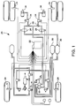
- Referring now to Figure 1, there is illustrated a block diagram of an existing combination anti-lock braking/drive traction regulation system shown generally by the
reference numeral 20. Thecombination system 20 includes anelectronic control module 22, multiplewheel speed sensors 24, multipleanti-lock brake valves 36, multiple double-check valves 28 and multiple high flowtraction control valves 26. - During the traction control event, the vehicle is accelerating and as such, there is torque applied to the
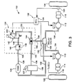
rear wheels 30. When theelectronic control module 22 senses a slipping rear wheel based upon data from thewheel speed sensors 24, it energizes thetraction control valve 26 on the slipping wheel only. This causes the pressure fromreservoirs 32 to be applied vialine 34 to the appropriate double-check valve 28, on through theanti-lock valve 36 and to the brake chamber 38. Applying the brakes to the slipping wheel causes the torque (which normally takes the path of least resistance) to be transferred to the non-slipping wheel, thus providing enhanced traction capability. Theanti-lock valve 36 will then be used to control the pressure on the slipping wheel such that the optimal traction condition can be maintained. A similar system which employs multiple valves and multiple double-check valves is described in United States patent number 4,819,995, issued to Löhmann et al. - Referring now to Figure 2, there is illustrated a block diagram for another existing combination anti-lock/traction control system, shown generally by
reference numeral 50. As shown, thecombination system 50 includes anelectronic control unit 52, multiplewheel speed sensors 54, a single high flowtraction control valve 56, multipleanti-lock brake valves 58 and multiple double-check valves 60. - During the traction control event, the vehicle is accelerating and as such, there is torque applied to the
rear wheels 62. When theelectronic control module 52 senses a slipping wheel based upon data from thewheel speed sensors 54, it energizes thetraction control valve 56 and energizes theABS valve 58 associated with the non-slipping wheel. Energizing thetraction control valve 56 results in air flow from thereservoir 64 to the double-check valves 60, thus causing them to seal off air to lines 66. This prevents the air from being exhausted out through the relay valve 68. This air then continues on to theABS valves 58. TheABS valve 58 associated with the non-slipping wheel is energized and as such, it does not allow air to flow to the associated brake chamber 70. TheABS valve 58 associated with the slipping wheel will allow air to pressurize the associated brake chamber 70 and as such, the torque will be transferred to the non-slipping wheel. Theanti-lock valve 58 will then be used to control the pressure on the slipping wheel such that the optimal traction condition can be maintained. - The design of both
traction control systems systems - It is, therefore, desirable to provide a traction control system with less components and that these components be of a less complex and less costly design level. Also, it is desirable to utilize a control pressure that is at a lower level than full system pressure.
- It is, therefore, an object of the present invention to provide an improved valve, for use with an anti-lock brake/traction control system, having less hardware, being less complex and less costly.
- It is further object of the present invention to provide an improved valve that utilizes a control pressure that is less than the system pressure.
- In carrying out the above objects, and other objects and features of the present invention, a valve is provided for use with an anti-lock brake/traction control system is provided. The valve is located on the control line of the relay valve, such that one low flow valve and one low flow double-check valve can be used. The valve also includes a pressure regulator, such that a more desirable control pressure can be attained. Most preferably, a pressure regulator, an electrically controlled low flow 3-way valve and a single double-check valve are preferably combined into one valve body thus simplifying the system even further.
- In further carrying out the above object and other objects and features of the present invention, a valve is provided, for use with a vehicular air brake system including an electronic control unit, for controlling air flow from a pressurized air supply to the brake system during two modes of vehicle operation. The valve comprises a valve body and a regulator assembly internal to the valve body in fluid communication with the pressurized air supply. The regulator assembly pressure-regulates the air supplied to the brake system during one of the two modes of operation. The valve also includes a solenoid valve internal to the valve body for receiving pressure-regulated air from the regulator assembly. The solenoid valve is controlled by the electronic control unit during the two modes of operation. The valve also includes a single double-check valve internal to the body and in fluid communication with the solenoid valve and the pressurized supply. The double-check valve allows the pressure-regulated air to flow from the solenoid valve to the brake system during the one mode of operation, and allows the pressurized air to flow from the pressurized air supply to the brake system during the other mode of operation.
- The advantages accruing to the present invention are numerous. For example, the valve of the present invention is designed to be incorporated into a standard air brake system that is configured with an existing anti-lock brake system and a relay valve on the rear brakes. The design of the valve is such that it will be located on the control, or low flow, side of the relay valve, as opposed to existing traction valves that are located on the output or high flow side of the relay valve. Valve complexity is reduced, reducing the associated cost.
- When energized, the solenoid valve portion of the present invention allows air at a regulated pressure to flow to the control line of the relay valve. The double-check valve portion of this invention seals off the portion of the relay valve control line that returns to the treadle valve, thus preventing this air from exhausting out to atmosphere through the treadle valve. The relay valve, being a flow amplifier for the rear brake chambers, provides a high flow source of air to the rear brake chambers at the regulated control pressure level determined by this invention.
- Upon energizing of the present invention, the electronic control unit energizes the anti-lock brake valve on the non-slipping wheel. This blocks the air to this wheel and applies the brakes to the slipping wheel, thus resulting in a transfer of torque and improved traction on the non-slipping wheel. When de-energized, this valve exhausts the pressure at the control line of the relay valve and, as such, causes the relay valve to exhaust pressure on the rear brakes. During normal operation, the double-check valve of the present invention shuttles to seal the normal relay valve control air from exhausting out to atmosphere through this invention.
- The above objects and other objects, features, and advantages of the present invention will be readily appreciated by one of ordinary skill in the art from the following detailed description of the best mode for carrying out the invention when taken in connection with the accompanying drawings.
-
- FIGURE 1 is a block diagram of an existing combination anti-lock brake/drive traction regulation system;
- FIGURE 2 is a block diagram illustrating another existing combination anti-lock brake/drive traction regulation system;
- FIGURE 3 is a block diagram of an improved combination anti-lock brake/drive traction regulation system, including a block diagram 100 of the valve of the present invention;
- FIGURE 4 is a side view of the valve shown by the block diagram in FIGURE 3 of the present invention;
- FIGURE 5 is a cross-section of the valve shown in FIGURE 4 taken along line 5-5, illustrating the internal pressure regulator; and
- FIGURE 6 is a cross-section partly in elevation of the valve shown in FIGURES 4 and 5, illustrating the internal solenoid valve and the single internal double-check valve.
- Referring now to Figure 3, there is illustrated a block diagram of a valve shown generally by
reference numeral 100 for use with a combination anti-lock brake/drive traction regulation system shown generally byreference numeral 102. As illustrated, thesystem 102 includes a pressurized source of air, ortank 104, atreadle valve 106 including abrake pedal 107, a brake airsystem relay valve 108, anti-lock braking system (ABS)valves air chambers wheel sensors wheels reference numeral 126. Based on this data, theelectronic control unit 126 can detect an impending lock-up ofwheels wheels electronic control unit 126 controls operation of thevalve 100 and theABS valves - With continuing reference to Figure 3, the
tank 104 supplies air under pressure to the supply ports ofvalve 100, thetreadle valve 106 and the brake airsystem relay valve 108. The air supplied from thetank 104 has a pressure associated with a typical compressor setting, such as 90-120 psi. Thus, air in that pressure range enters thevalve 100 throughsupply line 126 via the supply input port shown byreference numeral 128. Air in this pressure range also enters the brake airsystem relay valve 108 at thesupply input 130 viasupply line 132. Pressurized air is also supplied to thevalve 100 at thetreadle valve input 134 viatreadle supply line 136. The pressure of the air supplied to thevalve 100 from thetreadle valve 106 varies from zero psi to about 100 psi, depending on the force exerted by the vehicle operator on thebrake pedal 107. - As shown in Figure 3, the
valve 100 preferably has a body and includes an internal regulator assembly shown generally byreference numeral 140, an internal 3-way solenoid valve shown generally byreference numeral 142 and an internal single double-check valve shown generally byreference numeral 144. The regulator assembly, solenoid valve and double-check valve are described as internal since they are disposed within the body of the valve. Thesolenoid valve 142 is commercially available from Rostra Controls of Laurinburg, North Carolina, United States of America. The internalregulator assembly components 140, commercially available from Norgren Corporation of Littleton, Colorado, United States of America, are in fluid communication with thesupply line 126 from thetank 104. Theregulator assembly 140 functions to regulate the tank or brake system pressure down to a level of approximately 40 psi. - Referring now to Figures 4, 5 and 6, the
valve 100 is shown in greater detail. As best shown in Figure 5, theinternal regulator assembly 140 includes aspring 180, aspring retainer plate 182, arubber diaphragm 184, acavity 186, aguide bushing 188,plunger 190 and aspring 192 which surrounds theplunger 190. - With continuing reference to Figures 4 and 5, with no air pressure at
supply input port 128, thespring 180 expands, biasing thespring retainer plate 182 andrubber diaphragm 184 upward, such that the rod 196 comes into contact withplunger 190. When pressurized air is applied to thesupply input port 128, air flows through orifices 194 (shown in phantom) and fills thecavity 186. As the pressure rises incavity 186, thediaphragm 184 and thespring retainer plate 182 are biased downward. This continues until a point where the travel of rod 196 is such thatplunger 190 can be forced byspring 192 to seal on theguide bushing 188. This results in the pressure incavity 186 stabilizing at a steady value. - The spring rate of
spring 180 and the area of therubber diaphragm 184 determine the regulated pressure. In the preferred embodiment, thespring 180 has a spring rate value and thediaphragm 184 is sized such that the regulated pressure delivered to thesolenoid valve 142 throughfluid connection 148 is about 40 psi. - Referring now to Figure 6, a cross-section partly in elevation of the
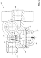
valve 100 is shown, illustrating the internalsolenoid valve assembly 142 and the single internal double-check valve 144. As shown in Figures 3 and 6, thevalve 100 includes aconnector receptacle 200. Electrical wires extend from thesolenoid valve 142 to the plurality ofcontacts 202. Thereceptacle 200 receives a connector plug (not shown), which is electrically connected by wires to theECU 126. - As best shown in Figure 6, the
solenoid valve 142 includes a port assembly shown generally byreference numeral 204. In the preferred embodiment, theport assembly 204 includes a pair of O-rings 206 and 208, and remains stationary within thevalve 100. A plunger assembly (not specifically illustrated) is positioned within theport assembly 204. The plunger assembly moves relative to theport assembly 204, in a known fashion, upon energization/deenergization of thesolenoid valve 142 by theECU 126 to control air flow to the single double-check valve 144. - With continuing reference to Figure 6, pressure regulated air from the
regulator assembly 140 is delivered to the lowflow solenoid valve 142 through thefluid connection 148. When theelectronic control unit 126 activates this solenoid to the energized state, a plunger (not specifically illustrated) in the valve moves upward, thus opening up an inlet port and sealing an exhaust port (not specifically illustrated). The pressurized air then flows through the valve and out the workingport 210. This air then travels downfluid connection 150 and on to thedouble check valve 144. When the low flow solenoid valve is de-energized, the plunger in the valve returns to its original state via a spring return. This seals off the inlet air and opens up the exhaust port, thus allowing the air that was supplied to thedouble check 144 throughfluid connection 150 to exhaust to atmosphere. - With combined reference to Figures 3 and 6, the
valve 100 is preferably machined to include a single internal double-check valve 144. Theball 214 of the double-check valve is biased from end to end therewithin in a known manner. As best shown in Figure 6, the double-check valve 144 preferably includes a plurality ofports 216 disposed radially around the central portion of the double-check valve. Most preferably, theports 216 are relatively small so as not to nick or otherwise damage the surface of theball 214 as it moves within the double-check valve 144. Theports 216 are in fluid communication with anannulus 218, which in turn is in fluid communication with the control air line port 158 (best shown in Figure 5). - In Figure 6, the
ball 214 is shown biased to one end due to air pressure entering the double-check valve 144 from the treadlevalve input port 134. This pressurized air then exits the double-check valve 144 through theports 216, theannulus 218 and the controlair line port 158, shown in Figures 4 and 5. The O-ring 220 functions as a seal to insure against air leaks. - Returning once again to Figure 3, operation of the
valve 100 will be discussed during normal braking and during traction control. Pressure regulated air from theregulator assembly 140 is communicated to thesolenoid valve 142 via thesupply air line 148. Theelectronic control unit 126 energizes thesolenoid valve 142 depending on whether a traction control situation exists. As described in greater detail below, theelectronic control unit 126 controls thesolenoid valve 142 to a deenergized state during normal braking and to an energized state during traction control. - During normal braking, the operator applies force to the
brake pedal 107, thus opening thetreadle valve 106 and supplying pressurized air from thetank 104 to theline 136 and on to thetreadle input port 134 of thetraction control valve 100. This pressurized air varies from 0 to approximately 100 psi depending upon the force applied by the operator on the brake pedal. The air flow through thetraction control valve 100 displaces the ball in thedouble check valve 144 away from the direction of flow, thus sealing off theinternal line 150 in the traction valve. This results in the air pressure being sealed from leaking out to atmosphere through the lowflow solenoid valve 142. The air, sealed from exhausting to atmosphere, now travels out of thetraction valve 100 via therelay port 158 and on to the control chamber of therelay valve 108. - In the preferred embodiment, the
relay valve 108 includes an internal piston and spring assembly. In its normal state, the spring biases the piston closed, thus sealing one port which allows the supply air fromtank 104 from being communicated to the brake chambers and also opening up another port which exhausts any air currently in the brake chambers to atmosphere. When air enters the control chamber vialine 160, this forces the piston downward, thus opening the supply port and closing the exhaust port in the relay valve. This allows air from thetank 104 to be communicated to the brake chambers. This air travels from thetank 104 throughline 132, and then through therelay valve 108. It continues downlines anti-lock valves brake chambers relay valve 108 acts as a flow amplifier by taking a small flow at a given pressure at the control port and converting it to a much larger flow at the same pressure at the outlet ports. - When the operator releases his foot from the
brake pedal 107, it in turn causes the air in the control port 133 of therelay valve 108 to be exhausted throughline 160 andline 136 out through thetreadle valve 106. Theball 214 in the double-check 144 of thetraction control valve 100 remains in the state it was previously in until the pressure in this line is exhausted. Removing the control pressure from the relay valve causes the piston to return to its original state, closing the supply port and opening the exhaust port for the brake chamber air. - During normal braking conditions, the
ECU 126 monitors thewheels wheel speed sensors ECU 126 controls theappropriate ABS valve - As previously mentioned, the
valve 100 provides thesystem 102 with traction control capabilities. Generally, a traction control situation arises as the vehicle is accelerated from a resting position. When accelerating hard or when accelerating during less than optimal driving conditions, the wheel having the lowest coefficient of friction surface can break free and spin on the road surface. This spinning wheel becomes the path of least resistance for the driveline, and all of the driveline torque flows out through that wheel, resulting in degraded vehicle acceleration and increased tire wear. By applying brake pressure to the spinning wheel, torque is transferred to a wheel having a higher coefficient of friction with the road surface. - With continuing reference to Figure 3, the
ECU 126 monitors thewheel speed sensors ECU 126 enters a traction control mode when thewheel speed sensors - For example, assume the vehicle is accelerating and the
ECU 126 has detected thatwheels 122 have lost traction and are spinning. To regain traction, theECU 126 energizes thesolenoid valve 142. As described in greater detail above, pressure regulated air (i.e. about 40 psi) from theregulator assembly 140 flows through thedelivery air line 150 to the double-check valve 144. Since the vehicle driver is not depressing thebrake pedal 107, this pressure regulated air biases theball 214 of the double-check valve 144 away from thedelivery air line 150, allowing the air to exit the double-check valve and flow to therelay valve 108 through thecontrol line 160. - The pressure regulated air displaces the internal piston of the
relay valve 108, and air at an equivalent pressure (i.e. about 40 psi) exits thevalve 108 and flows to theABS valve brake air lines - At the instant that the
ECU 126 energizes thetraction control valve 100, it also energizes theanti-lock brake valve 112 associated with thenon-slipping wheels 124. This blocks the flow of air to the non-slippingwheel brake chamber 116 and, as such, prevents brake torque from being applied to this wheel. Air is, however, allowed to pass to thebrake chamber 114 of the slipping wheel and thus, the brakes of this wheel are applied. By this method, the torque, which normally takes the path of least resistance (i.e. the slipping wheel), will be directed to the non-slipping side and, as such, allow the vehicle to accelerate. As the traction control event continues, theanti-lock brake valves - At speeds above about ten miles per hour or when the ECU determines that wheel slip is no longer present, the traction control valve will be de-energized. This will allow the air in the
control port 130 of therelay valve 108 to be exhausted vialines 160, traction control valveinternal line 150 and out through the exhaust port of thesolenoid 142. The ball in the double-check valve 144 of thetraction control valve 100 will remain in Position sealing off the treadle input line until the pressure in the valves drops to almost 0 psig. Exhausting the control air of the relay valve in turn causes the air in brake chambers to also be exhausted through the relay valve thus returning the entire brake system to its normal state. - One of ordinary skill in the art will recognize many advantages associated with the use of the
valve 100. For example, a combination anti-lock brake and traction control system can be designed utilizing less hardware than existing systems. A single smaller valve can be utilized, positioned on the control side of the brake system relay valve. Additionally, a substantial cost savings is realized, since mechanical hardware in the form of a mechanical traction interlock on the axle is no longer required. - It is understood, of course, that while the form of the invention herein shown and described constitutes the preferred embodiment of the invention, it is not intended to illustrate all possible forms thereof. It will also be understood that the words used are words of description rather than limitation, and that various changes may be made without departing from the spirit and scope of the invention as disclosed.
Claims (15)
- A valve (100), for use with a vehicular air brake system (102) including an electronic control unit (126), for controlling air flow from a pressurized air supply (104) to the brake system during two modes of vehicle operation, the valve comprising:
a valve body;
a regulator assembly (140) internal to the valve body in fluid communication with the pressurized air supply (104), the regulator assembly for pressure-regulating the air supplied to the brake system during one of the two modes of operation;
a solenoid valve (142) internal to the body for receiving pressure-regulated air from the regulator assembly (140), the solenoid valve being controlled by the electronic control unit (126) during the two modes of operation; and
a single double-check valve (144) internal to the body in fluid communication with the solenoid valve (142) and the pressurized supply (104), the double-check valve (144) allowing the pressure-regulated air to flow from the solenoid valve (142) to the brake system during the one mode of operation, and allowing the pressurized air to flow from the pressurized air supply (104) to the brake system during the other mode of operation. - The valve of claim 1 wherein the brake system includes a relay valve (108) having a control air line (160) in fluid communication with the double-check valve, the relay valve amplifying the flow and maintaining the pressure of the air provided to the brake system from the solenoid valve (142) during the one mode of operation.
- The valve of claim 2 wherein the relay valve (108) amplifies the flow and maintains the pressure of the air provided to the brake system from the pressurized supply during the other mode of operation.
- A valve (100) for controlling the traction of at least one vehicle wheel (122,124) slipping on road surface, the traction control valve for use with a vehicular air brake system (102) including at least one brake valve (110,112) controlled by an electronic control unit (126), the traction control valve comprising:
a valve body;
a regulator assembly (140) internal to the body for pressure-regulating the air supplied to the brake system;
a single double-check valve (144) internal to the body, the double-check valve allowing the pressure-regulated air to flow from the regulator assembly (140) to the at least one brake valve (110,112), the electronic control unit (126) controlling the at least one brake valve to apply brake pressure to the at least one slipping wheel (122,124) until traction with the road surface is obtained. - The valve of claim 4 further comprising a solenoid valve (142) internal to the body, the solenoid valve being controlled by the electronic control unit (126) to allow the pressure-regulated air to flow from the regulator assembly (140) to the double-check valve (144).
- The traction control valve of claim 5 wherein the brake system includes a relay valve (108) having a control air line (160) in fluid communication with the double-check valve (144), the relay valve amplifying the flow and maintaining the pressure of the air provided to the at least one brake valve (110,112) from the double-check valve (144).
- A traction control valve (100) for controlling the traction of at least one vehicle wheel (122,124) slipping on a road surface, the traction control valve for use with a vehicular air brake system (102) including at least one brake valve (110,112) controlled by an electronic control unit (126), the traction control valve comprising:
a valve body;
a regulator assembly (140) internal to the body, the regulator assembly for pressure-regulating the air supplied to the brake system;
a solenoid valve (142) internal to the body, the solenoid valve being controlled by the electronic control unit (126) to allow the pressure-regulated air to flow from the regulator assembly to the double-check valve; and
a single double-check valve (144) internal to the body, the double-check valve allowing the pressure-regulated air to flow from the solenoid valve (142) to the brake system, the electronic control unit (126) controlling the at least one brake valve (110,112) to apply brake pressure to the at least one slipping wheel (122,124) until traction with the road surface is obtained. - The valve of claim 7 wherein the brake system includes a pressurized air supply (104) and wherein the electronic control unit (126) controls the traction control valve during two modes of vehicle operation, such that pressure-regulated air from the regulator assembly (140) flows to the at least one brake valve (110,112) during one mode of operation, and air from the pressurized air supply flows to the at least one brake valve during the other mode of operation.
- A combination anti-lock air brake and traction control system (102) for use on a vehicle having at least one wheel (122,124) with a brake, the system being controlled by an electronic control unit (126) during two modes of vehicle operation, the system comprising:
a source of pressurized air (104);
an air brake system relay valve (108) in fluid communication with the source of pressurized air, the relay valve including a control air line (160);
at least one brake valve (110,112), positioned proximate the brake, for supplying air from the relay valve (108) to the brake, the at least one brake valve being controlled by the electronic control unit (126); and
a traction control valve (100) in fluid communication with the source of pressurized air (104) and the control air line (160) of the relay valve (108), the traction control valve including a valve body and a pressure regulator (140) internal to the body, a solenoid valve (142) internal to the body and a double-check valve (144) internal to the body, the electronic control unit (126) controlling the traction control valve (100) to apply the brake to the wheel during the two modes of vehicle operation. - The braking system of claim 9 wherein the traction control valve provides pressure-regulated air to the control air line (160) of the brake air system relay valve for distribution to the at least one brake valve (110,112) during one mode of vehicle operation, and wherein the traction control valve provides air from the pressurized source to the control air line (160) brake air system relay valve for distribution to the at least one brake valve (110,112) during the other mode of vehicle operation.
- The braking system of claim 10 wherein the one mode of operation is a traction control mode during which the at least one vehicle wheel (122,124) is slipping on a road surface, the electronic control unit (126) controlling the at least one brake valve (110,112) to apply brake pressure to the slipping wheel until traction with the road surface is obtained.
- The braking system of claim 10 wherein the other mode of operation is an anti-lock braking mode during which the at least one vehicle wheel (122,124) is skidding on a road surface, the electronic control unit (126) controlling the at least one brake valve (110,112) to vary brake pressure to the at least one wheel (122,124) until the at least one wheel rotates on the road surface.
- The braking system of claim 10 wherein the brake air system relay valve (108) amplifies the flow and maintains the pressure of the air provided to the brake valve from the double-check valve (144) during the one mode of operation.
- The braking system of claim 10 wherein the brake air system relay valve (108) amplifies the flow and maintains the pressure of the air provided to the brake valve from the pressurized supply during the other mode of operation.
- The braking system of claim 10 wherein the pressure-regulated air has a pressure of about 40 psi.
Applications Claiming Priority (2)
| Application Number | Priority Date | Filing Date | Title |
|---|---|---|---|
| US997345 | 1992-12-28 | ||
| US07/997,345 US5342119A (en) | 1992-12-28 | 1992-12-28 | Traction control system valve |
Publications (2)
| Publication Number | Publication Date |
|---|---|
| EP0604864A2 true EP0604864A2 (en) | 1994-07-06 |
| EP0604864A3 EP0604864A3 (en) | 1994-12-14 |
Family
ID=25543910
Family Applications (1)
| Application Number | Title | Priority Date | Filing Date |
|---|---|---|---|
| EP93120482A Withdrawn EP0604864A3 (en) | 1992-12-28 | 1993-12-18 | Traction control system and valve therefor. |
Country Status (11)
| Country | Link |
|---|---|
| US (1) | US5342119A (en) |
| EP (1) | EP0604864A3 (en) |
| JP (1) | JPH06227382A (en) |
| KR (1) | KR940014037A (en) |
| CN (1) | CN1093987A (en) |
| AR (1) | AR248243A1 (en) |
| AU (1) | AU662283B2 (en) |
| BR (1) | BR9305361A (en) |
| CA (1) | CA2111423A1 (en) |
| MX (1) | MX9400027A (en) |
| ZA (1) | ZA939628B (en) |
Cited By (8)
| Publication number | Priority date | Publication date | Assignee | Title |
|---|---|---|---|---|
| DE19729275A1 (en) * | 1997-07-09 | 1999-01-14 | Wabco Gmbh | Brake circuit for driven axle of car |
| US6306857B1 (en) | 1994-11-17 | 2001-10-23 | Molecular Geriatrics Corporation | Methods for treating or preventing alzheimer's disease using substituted 1-aryl-3-piperazin-1′-yl propanones |
| WO2009023486A1 (en) * | 2007-08-13 | 2009-02-19 | Bendix Commercial Vehicle Systems Llc | Valve with integrated quick release and method to control said valve |
| WO2011061179A1 (en) * | 2009-11-18 | 2011-05-26 | Knorr-Bremse Systeme für Nutzfahrzeuge GmbH | Main brake device of a vehicle having test run for valves |
| WO2011110459A1 (en) * | 2010-03-08 | 2011-09-15 | Knorr-Bremse Systeme für Nutzfahrzeuge GmbH | Modularly designed pressure control device of a pneumatic brake system of a vehicle |
| WO2012055911A3 (en) * | 2010-10-29 | 2012-08-23 | Knorr-Bremse Systeme für Nutzfahrzeuge GmbH | Pressure-medium-activated brake device of a vehicle having control routines, implemented in a brake controller unit, of a hill start assistant function or creep suppression function |
| WO2012113770A1 (en) * | 2011-02-24 | 2012-08-30 | Knorr-Bremse Systeme für Nutzfahrzeuge GmbH | Traction-controlled brake system of a motor vehicle which drives to stopping points |
| US9802593B2 (en) | 2011-06-07 | 2017-10-31 | Bendix Commercial Vehicle Systems Llc | Multi-pressure valve controller and method for a vehicle braking system |
Families Citing this family (14)
| Publication number | Priority date | Publication date | Assignee | Title |
|---|---|---|---|---|
| US5690396A (en) * | 1996-02-20 | 1997-11-25 | General Motors Corporation | Proportional fluid pressure regulation system |
| US5839801A (en) * | 1997-04-04 | 1998-11-24 | Itt Manufacturing Enterprises, Inc. | Variable tire pressure traction control enhancement |
| US20060017317A1 (en) * | 2004-07-22 | 2006-01-26 | Howell David W | Selective actuation of secondary circuit of dual brake valve |
| DE102008028440A1 (en) * | 2008-06-17 | 2009-12-31 | Knorr-Bremse Systeme für Nutzfahrzeuge GmbH | Pressure control valve arrangement with diaphragm valves for controlling a fluid pressure in an ABS brake system of a vehicle with integrally integrated in a housing part valve seat |
| US8078378B2 (en) * | 2008-12-31 | 2011-12-13 | Volvo Group North America, Inc. | Hill start assist system |
| US8869831B2 (en) | 2011-05-25 | 2014-10-28 | Bendix Commercial Vehicle Systems Llc | Variable configuration traction valve |
| US9120474B2 (en) * | 2011-06-15 | 2015-09-01 | Arvinmeritor Technology, Llc | Mechanical bypass valve for regenerative air brake module |
| US8820856B2 (en) | 2012-08-24 | 2014-09-02 | Matthew E. Rogers | Apparatus for setting park brakes of a heavy vehicle during a failure of a service brakes holding function of the vehicle |
| DE102016100526A1 (en) * | 2016-01-14 | 2017-07-20 | Knorr-Bremse Systeme für Nutzfahrzeuge GmbH | Control device for controlling a brake system for a vehicle, brake system for a vehicle, method for operating a control device and method for applying at least one braking device of a brake system for a vehicle with a brake pressure |
| US10150457B2 (en) * | 2016-04-28 | 2018-12-11 | Bendix Commercial Vehicle Systems Llc | Valve module for an air braking system of a heavy vehicle |
| DE102016010463A1 (en) * | 2016-08-31 | 2018-03-01 | Wabco Gmbh | Method for electronically controlling a pneumatic brake system in a vehicle, in particular a commercial vehicle, and electronically controllable pneumatic brake system |
| CN107298111B (en) * | 2017-05-26 | 2018-10-26 | 同济大学 | A kind of empty electrical brake system for goods train |
| CN110654359B (en) * | 2019-09-30 | 2020-10-02 | 清华大学 | Bridge module, pneumatic line control brake system and control method |
| US11938915B2 (en) * | 2021-03-17 | 2024-03-26 | Volvo Truck Corporat on | Braking arrangement for a vehicle |
Citations (4)
| Publication number | Priority date | Publication date | Assignee | Title |
|---|---|---|---|---|
| US3706351A (en) * | 1971-01-25 | 1972-12-19 | North American Rockwell | Differential control |
| US4156547A (en) * | 1977-08-23 | 1979-05-29 | Aspro, Inc. | Speed-responsive anti-skid and anti-spin system for vehicles |
| EP0274610A2 (en) * | 1987-01-13 | 1988-07-20 | WABCO Westinghouse Fahrzeugbremsen GmbH | Vehicle with an anti-locking system and traction control |
| DE3942564A1 (en) * | 1989-12-22 | 1991-06-27 | Bosch Gmbh Robert | Control or working unit for vehicle braking system - makes use of double check-valve integral with unit housing |
Family Cites Families (7)
| Publication number | Priority date | Publication date | Assignee | Title |
|---|---|---|---|---|
| US3768519A (en) * | 1971-11-16 | 1973-10-30 | Bendix Corp | Modulator for adaptive braking system |
| DE2810151A1 (en) * | 1978-03-09 | 1979-09-13 | Bosch Gmbh Robert | PRESSURE CONTROL VALVE UNIT I |
| DE3431326A1 (en) * | 1984-08-25 | 1986-03-06 | Robert Bosch Gmbh, 7000 Stuttgart | VEHICLE BRAKE SYSTEM WITH ANTI-BLOCKING DEVICE |
| DE3800854A1 (en) * | 1988-01-14 | 1989-07-27 | Bosch Gmbh Robert | BRAKE SYSTEM WITH ANTI-BLOCKING AND DRIVE-SLIP CONTROL |
| EP0387004A3 (en) * | 1989-03-08 | 1990-11-22 | LUCAS INDUSTRIES public limited company | Trailer braking system for a towing vehicle |
| DE3921078A1 (en) * | 1989-06-28 | 1991-01-03 | Bosch Gmbh Robert | COMPRESSED AIR BRAKE SYSTEM WITH AN ANTI-BLOCKING DEVICE |
| DE4114861A1 (en) * | 1991-05-07 | 1992-11-12 | Wabco Westinghouse Fahrzeug | VEHICLE WITH LIFTABLE REAR AXLE |
-
1992
- 1992-12-28 US US07/997,345 patent/US5342119A/en not_active Expired - Lifetime
-
1993
- 1993-12-14 CA CA002111423A patent/CA2111423A1/en not_active Abandoned
- 1993-12-18 EP EP93120482A patent/EP0604864A3/en not_active Withdrawn
- 1993-12-22 ZA ZA939628A patent/ZA939628B/en unknown
- 1993-12-22 AU AU52661/93A patent/AU662283B2/en not_active Expired - Fee Related
- 1993-12-22 AR AR93326992A patent/AR248243A1/en active
- 1993-12-27 KR KR1019930029867A patent/KR940014037A/en not_active Application Discontinuation
- 1993-12-27 BR BR9305361A patent/BR9305361A/en not_active Application Discontinuation
- 1993-12-28 CN CN93121755A patent/CN1093987A/en active Pending
- 1993-12-28 JP JP5334184A patent/JPH06227382A/en active Pending
-
1994
- 1994-01-03 MX MX9400027A patent/MX9400027A/en unknown
Patent Citations (4)
| Publication number | Priority date | Publication date | Assignee | Title |
|---|---|---|---|---|
| US3706351A (en) * | 1971-01-25 | 1972-12-19 | North American Rockwell | Differential control |
| US4156547A (en) * | 1977-08-23 | 1979-05-29 | Aspro, Inc. | Speed-responsive anti-skid and anti-spin system for vehicles |
| EP0274610A2 (en) * | 1987-01-13 | 1988-07-20 | WABCO Westinghouse Fahrzeugbremsen GmbH | Vehicle with an anti-locking system and traction control |
| DE3942564A1 (en) * | 1989-12-22 | 1991-06-27 | Bosch Gmbh Robert | Control or working unit for vehicle braking system - makes use of double check-valve integral with unit housing |
Cited By (14)
| Publication number | Priority date | Publication date | Assignee | Title |
|---|---|---|---|---|
| US6306857B1 (en) | 1994-11-17 | 2001-10-23 | Molecular Geriatrics Corporation | Methods for treating or preventing alzheimer's disease using substituted 1-aryl-3-piperazin-1′-yl propanones |
| DE19729275A1 (en) * | 1997-07-09 | 1999-01-14 | Wabco Gmbh | Brake circuit for driven axle of car |
| WO2009023486A1 (en) * | 2007-08-13 | 2009-02-19 | Bendix Commercial Vehicle Systems Llc | Valve with integrated quick release and method to control said valve |
| US7780245B2 (en) | 2007-08-13 | 2010-08-24 | Bendix Commercial Vehicle Systems Llc | Valve with integrated quick release |
| US8870299B2 (en) | 2009-11-18 | 2014-10-28 | Knorr-Bremse Systeme Fuer Nutzfahrzeuge Gmbh | Main brake device of a vehicle having test run for valves |
| WO2011061179A1 (en) * | 2009-11-18 | 2011-05-26 | Knorr-Bremse Systeme für Nutzfahrzeuge GmbH | Main brake device of a vehicle having test run for valves |
| EP2915710A1 (en) * | 2009-11-18 | 2015-09-09 | KNORR-BREMSE Systeme für Nutzfahrzeuge GmbH | Operating brake device of a vehicle having test run for valves |
| US8918262B2 (en) | 2010-03-08 | 2014-12-23 | Knorr-Bremse Systeme Fuer Nutzfahrzeuge Gmbh | Modularly designed pressure control device of a fluid pressure brake system of a vehicle |
| WO2011110459A1 (en) * | 2010-03-08 | 2011-09-15 | Knorr-Bremse Systeme für Nutzfahrzeuge GmbH | Modularly designed pressure control device of a pneumatic brake system of a vehicle |
| WO2012055911A3 (en) * | 2010-10-29 | 2012-08-23 | Knorr-Bremse Systeme für Nutzfahrzeuge GmbH | Pressure-medium-activated brake device of a vehicle having control routines, implemented in a brake controller unit, of a hill start assistant function or creep suppression function |
| US9193338B2 (en) | 2010-10-29 | 2015-11-24 | Knorr-Bremse Systeme Fuer Nutzfahrzeuge Gmbh | Pressure-medium-activated brake device of a vehicle having control routines implemented in a brake controller unit, of a hill start assistant function or creep suppression function |
| WO2012113770A1 (en) * | 2011-02-24 | 2012-08-30 | Knorr-Bremse Systeme für Nutzfahrzeuge GmbH | Traction-controlled brake system of a motor vehicle which drives to stopping points |
| US9505386B2 (en) | 2011-02-24 | 2016-11-29 | Knorr-Bremse Systeme Fuer Nutzfahrzeuge Gmbh | Traction-slip controlled brake system of a motor vehicle approaching stops |
| US9802593B2 (en) | 2011-06-07 | 2017-10-31 | Bendix Commercial Vehicle Systems Llc | Multi-pressure valve controller and method for a vehicle braking system |
Also Published As
| Publication number | Publication date |
|---|---|
| ZA939628B (en) | 1994-08-15 |
| CN1093987A (en) | 1994-10-26 |
| CA2111423A1 (en) | 1994-06-29 |
| AU662283B2 (en) | 1995-08-24 |
| KR940014037A (en) | 1994-07-16 |
| JPH06227382A (en) | 1994-08-16 |
| US5342119A (en) | 1994-08-30 |
| BR9305361A (en) | 1994-07-05 |
| AU5266193A (en) | 1994-07-07 |
| MX9400027A (en) | 1994-07-29 |
| AR248243A1 (en) | 1995-07-12 |
| EP0604864A3 (en) | 1994-12-14 |
Similar Documents
| Publication | Publication Date | Title |
|---|---|---|
| US5342119A (en) | Traction control system valve | |
| US5445444A (en) | Automatic braking procedure for motor vehicles with an ABS | |
| CN1057495C (en) | Process for operating anti-lock moter vehicle braking system | |
| US4844558A (en) | Brake fluid pressure control apparatus in skid control system | |
| US4565411A (en) | Hydraulic brake system with slip control | |
| EP0580382B1 (en) | Braking systems | |
| US4836618A (en) | Brake control system for controlling a braking force to each wheel of a motor vehicle | |
| US5383719A (en) | Hydraulic braking systems for vehicles | |
| EP0285253A2 (en) | Vehicle brake control apparatus | |
| EP0358645B1 (en) | Traction system utilizing ''pump back'' based abs system | |
| US4869560A (en) | Hydraulic braking system for a vehicle | |
| JPH06206532A (en) | Hydraulic automobile brake with skid control device | |
| EP0236085A1 (en) | Improvements in fluid-pressure operated anti-skid braking systems for vehicles | |
| US6217129B1 (en) | Vehicular brake system with vehicle stability management | |
| US6048040A (en) | Vehicle braking system with drive wheel slip control | |
| US5326160A (en) | Hydraulic systems for vehicles | |
| JPS61102336A (en) | Braking device for vehicles | |
| EP0503873B1 (en) | Braking system for vehicle | |
| JPH0773991B2 (en) | Brake system with slip control | |
| JP3900625B2 (en) | Brake device | |
| US4930846A (en) | Anti-lock control apparatus | |
| US4932728A (en) | Vehicle brake control system | |
| US5971502A (en) | Secondary braking control | |
| US3989313A (en) | Pressure control valve for hydraulic braking systems of wheeled vehicles | |
| KR100358735B1 (en) | How to control solenoid valve of anti-lock brake system |
Legal Events
| Date | Code | Title | Description |
|---|---|---|---|
| PUAI | Public reference made under article 153(3) epc to a published international application that has entered the european phase |
Free format text: ORIGINAL CODE: 0009012 |
|
| AK | Designated contracting states |
Kind code of ref document: A2 Designated state(s): DE ES FR GB IT SE |
|
| PUAL | Search report despatched |
Free format text: ORIGINAL CODE: 0009013 |
|
| AK | Designated contracting states |
Kind code of ref document: A3 Designated state(s): DE ES FR GB IT SE |
|
| 17P | Request for examination filed |
Effective date: 19950602 |
|
| 17Q | First examination report despatched |
Effective date: 19951019 |
|
| STAA | Information on the status of an ep patent application or granted ep patent |
Free format text: STATUS: THE APPLICATION IS DEEMED TO BE WITHDRAWN |
|
| 18D | Application deemed to be withdrawn |
Effective date: 19960301 |