EP0605585B1 - Method for making a composite part with an antiabrasion surface, and parts obtained by such method - Google Patents
Method for making a composite part with an antiabrasion surface, and parts obtained by such method Download PDFInfo
- Publication number
- EP0605585B1 EP0605585B1 EP92920632A EP92920632A EP0605585B1 EP 0605585 B1 EP0605585 B1 EP 0605585B1 EP 92920632 A EP92920632 A EP 92920632A EP 92920632 A EP92920632 A EP 92920632A EP 0605585 B1 EP0605585 B1 EP 0605585B1
- Authority
- EP
- European Patent Office
- Prior art keywords
- antiabrasion
- substrate
- glue
- tungsten carbide
- abrasion
- Prior art date
- Legal status (The legal status is an assumption and is not a legal conclusion. Google has not performed a legal analysis and makes no representation as to the accuracy of the status listed.)
- Expired - Lifetime
Links
Images


Classifications
-
- C—CHEMISTRY; METALLURGY
- C22—METALLURGY; FERROUS OR NON-FERROUS ALLOYS; TREATMENT OF ALLOYS OR NON-FERROUS METALS
- C22C—ALLOYS
- C22C1/00—Making non-ferrous alloys
- C22C1/10—Alloys containing non-metals
- C22C1/1036—Alloys containing non-metals starting from a melt
-
- C—CHEMISTRY; METALLURGY
- C23—COATING METALLIC MATERIAL; COATING MATERIAL WITH METALLIC MATERIAL; CHEMICAL SURFACE TREATMENT; DIFFUSION TREATMENT OF METALLIC MATERIAL; COATING BY VACUUM EVAPORATION, BY SPUTTERING, BY ION IMPLANTATION OR BY CHEMICAL VAPOUR DEPOSITION, IN GENERAL; INHIBITING CORROSION OF METALLIC MATERIAL OR INCRUSTATION IN GENERAL
- C23C—COATING METALLIC MATERIAL; COATING MATERIAL WITH METALLIC MATERIAL; SURFACE TREATMENT OF METALLIC MATERIAL BY DIFFUSION INTO THE SURFACE, BY CHEMICAL CONVERSION OR SUBSTITUTION; COATING BY VACUUM EVAPORATION, BY SPUTTERING, BY ION IMPLANTATION OR BY CHEMICAL VAPOUR DEPOSITION, IN GENERAL
- C23C26/00—Coating not provided for in groups C23C2/00 - C23C24/00
- C23C26/02—Coating not provided for in groups C23C2/00 - C23C24/00 applying molten material to the substrate
Definitions
- the present invention relates to the manufacture of composite metal parts comprising a contact coating intended to resist abrasion.
- Such mechanical parts known as “wearing parts” are known, which are superficially reinforced by the addition of a material having improved characteristics in terms of resistance to wear by abrasion.
- the present invention relates more particularly to hard reloads using a structure of grains of high hardness bonded together by a metal alloy which is commonly referred to as the metallic matrix.
- the grains of high hardness can advantageously be grains based on tungsten carbide.
- a first known technique for producing an abrasion-resistant coating is hard surfacing by welding.
- rigid rods or flexible rods are used, one end of which is applied to the surface to be recharged and is subjected to an electric arc or to an oxyacetylene flame.
- the rod includes a tungsten carbide powder embedded in an alloy based on nickel or other suitable metals.
- Such hard surfacing obtained with tungsten carbide rods has drawbacks, however: in particular, the welding processes lead to depositing the surfacing in the form of successive beads, juxtaposed side by side one after the other. It is understood that the realization of a relatively large area using such a technique is tedious, and requires a certain dexterity and a certain habit on the part of the operator. On the other hand, the waves inherent in such a material deposition process, reproducing the shape of the successive beads, cause thickness irregularities of up to several millimeters.
- Document FR-A-814 171 describes a process for producing a shaped part by sintering in the liquid phase, in which a mixture of carbide chips and molten metal powder is introduced into a carbon mold. The shaped part is melted under pressure. Such a process causes, during the fusion, a significant dimensional shrinkage.
- a more advanced technique for producing a layer of abrasion-resistant material is described in document FR-A-1 398 732. It is an infiltration technique, in which a hollow mold made of carbon or ceramic material is used having a desired shape; a metal substrate is placed in the hollow of the mold, opposite the mold molding walls; filling with grains of tungsten carbide or equivalent the hollow interior space between the substrate and the mold molding walls, vibrating the assembly to pack the grains; grains or pellets of metal or of alloy binder are placed above the grains of carbide; the assembly is heated to a temperature above the melting temperature of the alloy and below the melting temperature of the core and the mold. The rise in temperature ensures the melting of the alloy or binder metal, which infiltrates into the space filled with tungsten carbide grains, and ensures the welding with the metal substrate. It is then left to cool and can be removed from the mold.
- This infiltration technique is quite suitable for parts in which a convex substrate is of relatively small dimensions, and of relatively compact shape, the abrasion-resistant layer being relatively massive.
- the technique is also suitable when the substrate is concave.
- the abrasion-resistant coating tends to break under the action of impacts, and that in particular this coating does not allow subsequent re-machining after infiltration.
- the weld between the thickness of the abrasion-resistant material and the metal substrate is of poor quality.
- this technique of infiltration on a metal substrate does not allow the production of a part that is mechanically strong enough to constitute a needle for a needle valve used in hydroelectric plants. Indeed, during the closing of the needle on its seat, the anti-abrasion coating of the needle tends to burst under the effect of shocks and mechanical stresses occurring at this closing time.
- the problem proposed by the present invention is to ensure satisfactory mechanical resistance to an abrasion-resistant coating based on infiltrated tungsten carbide grains covering a substrate of a different nature, the assembly constituting a composite part.
- Such a composite part must have qualities of mechanical resistance at the surface sufficient to withstand shocks, and to allow possible re-machining of its abrasion-resistant coating surface without cracking or falling apart.
- the idea which is the basis of the present invention is that the defects observed in mechanical strength of the abrasion-resistant coatings based on tungsten carbide grains produced by infiltration on a substrate would result from differential expansions occurring during infiltration.
- the entire substrate and the surface reloading of tungsten carbide grains must be brought to a temperature sufficient for the melting of the alloy or binder metal which must infiltrate into space. filled with tungsten carbide grains and which must ensure the weld with the substrate.
- the metal substrate expands appreciably, while the grains of tungsten carbide which form a compact stack expand very little, roll on each other and can thus follow the expansion of the mold and the substrate.
- the tungsten carbide grains tend to roll over each other, which allows them to occupy all the space between the mold and the substrate.
- the tungsten carbide grains no longer have the possibility of rolling over one another, since they are bonded by the alloy or binder metal, so that the abrasion-resistant coating can no longer be shrink by a coefficient similar to that of the substrate.
- abrasion-resistant parts obtained by infiltration appear advantageous, because the abrasion-resistant surface thus obtained by infiltration exhibits remarkable properties of abrasion resistance.
- infiltration makes it possible to produce abrasion-resistant surfaces having particularly regular and smooth shapes, promoting the efficiency of the parts thus produced.
- a valve needle for a hydroelectric plant such a needle must have a very regular conical surface allowing efficient sealing.
- the surfaces In the case of a kneading tooth or a paving stone of a kneading cylinder, the surfaces must also be regular, so as not to impede the flow of the fluid to be kneaded.
- the object of the present invention is therefore to produce parts for which the abrasion-resistant coating is obtained by infiltration of alloy into a stack of tungsten carbide grains, these parts having, after production, markedly improved qualities of mechanical resistance to impact resistance. , avoiding separation between the substrate and its abrasion-resistant layer.
- such parts with abrasion-resistant coating can be obtained at low cost, in particular when the parts are large dimensions, lowering costs being obtained in particular by reducing the risk of waste.
- Another advantage of the invention is that it becomes possible to produce relays or abrasion-resistant coatings on substrates which are themselves liable to not withstand temperatures as high as that necessary for melting the alloy or binder metal during infiltration. It is thus possible to design a part made of composite material in which the substrate can be non-metallic, associated with a layer of abrasion-resistant material based on infiltrated tungsten carbide grains.
- the substrate can be made of steel.
- the glue used for bonding can be an epoxy glue.
- the epoxy adhesive is of a single-component or poly-component type which can be polymerized under heat.
- the bonding step then comprises a step of heating to an appropriate temperature for the duration of polymerization of the adhesive.
- an alloy infiltration technique is used in a stack of tungsten carbide grains.
- the mold used is advantageously a mold for molding walls in foundry sand bound by resins.
- a difficulty is then encountered because the mold comprises walls whose surface is relatively large relative to the volume of the abrasion-resistant layer to be produced, since this layer generally does not have to have a very large thickness relative to its surface. The difficulty then appears by the fact that the resin used to bind the sand of the mold tends to be consumed during infiltration, and interferes with the production of a good quality abrasion-resistant layer.
- the amount of resin will be less than 6% by weight of the amount of foundry sand.
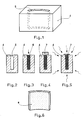
- FIGS. 10 and 13 to 14 illustrate the internal structure of the composite parts with abrasion-resistant coating obtained by a method according to the present invention.
- these parts comprise a substrate 1 covered at least in part by a layer of abrasion-resistant material 2 which is secured to it by an intermediate layer 3 of adhesive.
- Smelter mixers include a cylindrical tubular enclosure, several meters long, with a diameter of around 60 centimeters, intended to contain a carbon paste to be kneaded by kneader teeth. Some teeth are mounted fixed on the wall of the enclosure and protrude towards the inside of the enclosure, other teeth are mounted on a rotor rotating axially in the enclosure. The kneading teeth are for example as shown in longitudinal section in FIGS. 14 and 15.
- FIGS. 1 to 6 one of the coating elements made of abrasion-resistant material which will be used to cover the internal surface of the cylindrical enclosure is produced by infiltration of a binder alloy into a stack of tungsten carbide grains of mixer.
- a hollow mold 4 is prepared, comprising an interior recess 5 delimited by molding walls having the shape of the surface element made of abrasion-resistant material to be produced. This mold is shown empty in section in FIG. 2.
- FIG. 3 we introduce into the recess 5 of the mold 4 particles 6 of hard material such as molten tungsten carbide, vibrating the assembly, so that the surface particles come to bear against the mold walls as much as possible and are joined to each other.
- a sufficient quantity of an appropriate alloy 7 is prepared in suitable form, to ensure a subsequent distribution of the alloy during its subsequent melting phase.
- the alloy 7 is a brazing alloy capable of wetting the particles of hard material and of melting at a temperature below the melting temperature of the particles of hard material 6 and of the mold 4.
- FIG. 5 the assembly is heated of the mold 4 and its content up to a temperature above the melting temperature of the alloy 7 and below the melting temperature of the hard material particles 6 and of the mold 4.
- This temperature is maintained for a sufficient time to ensuring the infiltration of the molten alloy 7 into the space filled with particles of hard material 6. It is then allowed to cool, and it is removed from the mold, in order to obtain the element 8 of coating made of abrasion-resistant material shown in FIG. 6.
- FIGS. 7 and 8 the substrate intended to receive the coating elements made of abrasion-resistant material is prepared.
- FIG. 7 we start from a rectangular sheet 9.
- this rectangular sheet 9 is bent to give it a semi-cylindrical shape of suitable diameter so that, after affixing of the elements of coating made of abrasion-resistant material, the internal diameter of the assembly is in accordance with the diameter of the mixer tube to be produced.
- FIG. 9 the assembly and the attachment of the abrasion-resistant coating elements such as the element 8 are carried out on the substrate 1 such as the curved sheet metal.
- This attachment is effected by gluing, by applying the said abrasion-resistant coating elements 8 on the substrate 1 of curved sheet 9 with the interposition of an appropriate layer of adhesive.
- FIG. 10 is a longitudinal section along the axis I-I in FIG. 9, the assembly thus obtained, showing the abrasion-resistant layer 2, the substrate 1 or sheet 9 and the intermediate layer of glue 3.
- the adhesive 3 used is an epoxy adhesive, preferably of a single-component or poly-component type which can be polymerized hot.
- the assembly and bonding step shown on FIG. 9 comprises a step of heating to an appropriate temperature during the polymerization time of the glue 3.
- abrasion-resistant coating elements 8 After assembly of the abrasion-resistant coating elements 8 on the substrate 1 of curved sheet metal 9, it is advantageously possible to provide for a subsequent step of machining the excess glue and the edges of the abrasion-resistant surface, in order to produce semi-cylindrical elements which can be arranged. one after the other edge-to-edge without the appearance of cracks or gaps between two adjacent elements.
- the mechanical resistance thus obtained from all of the abrasion-resistant elements bonded to the sheet 9 is sufficient so that the abrasion-resistant surface can be subsequently equalized during a subsequent machining step.
- the mold 4 used can be made of different materials.
- a more advantageous solution consists in using a mold 4 comprising molding walls made of foundry sand bound by resins.
- the recess 5 is then produced by immersing a model in the mold 4 before setting the resin, and removing the model after setting the resin, according to a traditional technique in molding for the casting of metals.
- the abrasion-resistant coating element 8 to be formed has a very large surface area in relation to its volume. This is due to the fact that the covering element is generally flat.
- the problem that can occur is that, during infiltration, the combustion of the resin binding the sand of the mold 4 produces gas emissions which tend to seep into the recess 5 filled with hard abrasion-resistant particles 6. These gas evolution can form deposits on the particles, and, if these deposits are in excess, they can harm the wetting of the particles by the binder alloy 7 during infiltration. This then results in a poor quality of mechanical strength of the abrasion-resistant element 8 thus produced.
- the quantity of resin present in the mold 4 is adjusted to be just sufficient to maintain the foundry sand until infiltration. In practice, the amount of resin can be chosen to be less than 6% by weight of the amount of mold foundry sand 4.
- a composite part shown in Figure 9, comprising a sheet metal substrate 1 9 of semi-cylindrical steel shape, with, on the inner surface of the half-cylinder , a layer of polymerized neck adhering to the half-cylinder and, adhering to the layer of polymerized glue and surmounting it, a paving of plates or abrasion-resistant coating elements 8 in the form of a sector of cylinder with generally rectangular outline, the paving according to the curvature of the inner surface of the half-cylinder, the assembly forming a shielding plate for an aluminum mixer.
- the composite part obtained by the method of the invention comprises a steel substrate 1 having a generally convex shape.
- a layer of polymerized adhesive 3 On the exterior surface of the substrate, there is a layer of polymerized adhesive 3.
- a cap 2 Overlying said layer of glue 3, there is a cap 2 made of abrasion-resistant material.
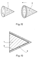
- Figures 11 to 13 relate to the production of a needle valve needle used in hydroelectric plants.
- a needle is of conical shape, and comprises a conical substrate 1 of steel whose conical outer surface is covered with a conical cap 2 forming an element made of abrasion-resistant material.
- the substrate 1 and the cap 2 are produced separately.
- the cap 2 is itself produced by infiltration, as shown diagrammatically in FIG. 11, in a mold 4 comprising a removable core. 40, the mold 4 forming the outer surface of the cap, the core 40 forming the inner surface of the conical cap.
- the cap 2 is adapted on the substrate 1, as shown in FIG. 12, with the interposition of a layer of glue, and the needle is obtained as shown in section in FIG. 13, presenting the cap 2 , the substrate 1 and the intermediate layer of adhesive 3.
- FIGS. 14 and 15 relate to the production of an aluminum blender tooth.
- the part must advantageously have the shape shown in the figures. This part is formed according to a process similar to that described in relation to the previous figures, by separately producing the substrate 1 and the cap 2, the cap 2 being obtained by infiltration in a mold.
- the assembly of the substrate and the cap by gluing allows the intermediate adhesive 3 to act as a damper between the substrate 1 and the abrasion-resistant element 2. It increases considerably the apparent mechanical resistance of the abrasion-resistant coating thus produced, so that subsequent re-machining of its surface is made possible.
- the part has a significantly improved impact resistance compared to production techniques by overmolding infiltration.
- this technique according to the present invention avoids heating the substrate 1, so that one does not alter its external appearance.
- the heating of the substrate 1, when it is made of steel causes an alteration of its surface and requires re-machining.
Abstract
Description
La présente invention concerne la fabrication des pièces métalliques composites comportant un revêtement de contact destiné à résister à l'abrasion.The present invention relates to the manufacture of composite metal parts comprising a contact coating intended to resist abrasion.
On connaît de telles pièces mécaniques dites "pièces d'usure", qui sont renforcées superficiellement par l'apport d'un matériau présentant des caractéristiques améliorées au plan de la résistance à l'usure par abrasion.Such mechanical parts known as “wearing parts” are known, which are superficially reinforced by the addition of a material having improved characteristics in terms of resistance to wear by abrasion.
La présente invention concerne plus particulièrement les rechargements durs mettant en oeuvre une structure de grains de haute dureté liés entre eux par un alliage métallique que l'on désigne communément sous le terme de matrice métallique. Les grains de haute dureté peuvent avantageusement être des grains à base de carbure de tungstène.The present invention relates more particularly to hard reloads using a structure of grains of high hardness bonded together by a metal alloy which is commonly referred to as the metallic matrix. The grains of high hardness can advantageously be grains based on tungsten carbide.
Une première technique connue pour réaliser un revêtement antiabrasion est le rechargement dur par soudage. On utilise par exemple des baguettes rigides ou des baguettes souples, dont une extrémité est appliquée sur la surface à recharger et est soumise à un arc électrique ou à une flamme oxyacétylénique. La baguette comprend une poudre de carbure de tungstène noyée dans un alliage à base de nickel ou d'autres métaux appropriés.A first known technique for producing an abrasion-resistant coating is hard surfacing by welding. For example, rigid rods or flexible rods are used, one end of which is applied to the surface to be recharged and is subjected to an electric arc or to an oxyacetylene flame. The rod includes a tungsten carbide powder embedded in an alloy based on nickel or other suitable metals.
Un tel rechargement dur obtenu avec des baguettes à base de carbure de tungstène présente toutefois des inconvénients : en particulier, les procédés de soudage conduisent à déposer le rechargement sous forme de cordons successifs, juxtaposés côte-à-côte les uns après les autres. On comprend que la réalisation d'une surface relativement importante à l'aide d'une telle technique est fastidieuse, et requiert une certaine dextérité et une certaine habitude de la part de l'opérateur. D'autre part, les vagues inhérentes à un tel procédé de dépôt de matières, reproduisant la forme des cordons successifs, entraînent des irrégularités d'épaisseur pouvant atteindre plusieurs millimètres.Such hard surfacing obtained with tungsten carbide rods has drawbacks, however: in particular, the welding processes lead to depositing the surfacing in the form of successive beads, juxtaposed side by side one after the other. It is understood that the realization of a relatively large area using such a technique is tedious, and requires a certain dexterity and a certain habit on the part of the operator. On the other hand, the waves inherent in such a material deposition process, reproducing the shape of the successive beads, cause thickness irregularities of up to several millimeters.
Il en résulte que cette technique ne permet pas de réaliser des pièces dont les dimensions sont précises, ou dont les formes sont complexes.As a result, this technique does not make it possible to produce parts whose dimensions are precise, or whose shapes are complex.
Le document FR-A-814 171 décrit un procédé de réalisation de pièce de forme par frittage en phase liquide, dans lequel on introduit dans un moule en carbone un mélange d'éclats de carbure et de poudre de métal de fusion. La pièce de forme est fondue sous pression. Un tel procédé entraîne, au cours de la fusion, un retrait dimensionnel important.Document FR-A-814 171 describes a process for producing a shaped part by sintering in the liquid phase, in which a mixture of carbide chips and molten metal powder is introduced into a carbon mold. The shaped part is melted under pressure. Such a process causes, during the fusion, a significant dimensional shrinkage.
On connaît également, du document US-A-4 307 845, un broyeur comportant des barreaux massifs en céramique fixés par collage sur une pièce support intermédiaire elle-même solidarisée au broyeur par un boulon. Ce document ne comporte aucun enseignement relatif à la fabrication du barreau massif en céramique, et son objet est très éloigné de la réalisation d'un revêtement antiabrasion.Also known, from document US-A-4 307 845, a crusher comprising solid ceramic bars fixed by gluing to an intermediate support piece itself secured to the crusher by a bolt. This document contains no teaching relating to the manufacture of the solid ceramic bar, and its object is far removed from the production of an abrasion-resistant coating.
Une technique plus évoluée de réalisation de couche en matière antiabrasion est décrite dans le document FR-A-1 398 732. Il s'agit d'une technique d'infiltration, dans laquelle on utilise un moule creux en carbone ou en matière céramique ayant une forme désirée ; on place un substrat métallique dans le creux du moule, en regard des parois de moulage du moule ; on remplit avec des grains de carbure de tungstène ou équivalent l'espace intérieur creux compris entre le substrat et les parois de moulage du moule, en vibrant l'ensemble pour tasser les grains ; on place des grains ou pastilles de métal ou d'alliage liant au-dessus des grains de carbure ; on chauffe l'ensemble à une température supérieure à la température de fusion de l'alliage et inférieure à la température de fusion du noyau et du moule. L'élévation de temperature assure la fusion de l'alliage ou métal liant, qui s'infiltre dans l'espace rempli de grains de carbure de tungstène, et assure la soudure avec le substrat métallique. On laisse ensuite refroidir et on peut démouler.A more advanced technique for producing a layer of abrasion-resistant material is described in document FR-A-1 398 732. It is an infiltration technique, in which a hollow mold made of carbon or ceramic material is used having a desired shape; a metal substrate is placed in the hollow of the mold, opposite the mold molding walls; filling with grains of tungsten carbide or equivalent the hollow interior space between the substrate and the mold molding walls, vibrating the assembly to pack the grains; grains or pellets of metal or of alloy binder are placed above the grains of carbide; the assembly is heated to a temperature above the melting temperature of the alloy and below the melting temperature of the core and the mold. The rise in temperature ensures the melting of the alloy or binder metal, which infiltrates into the space filled with tungsten carbide grains, and ensures the welding with the metal substrate. It is then left to cool and can be removed from the mold.
Cette technique d'infiltration convient assez bien pour des pièces dans lesquelles un substrat convexe est de dimensions relativement faibles, et de forme relativement compacte, la couche antiabrasion étant relativement massive. La technique convient également lorsque le substrat est concave.This infiltration technique is quite suitable for parts in which a convex substrate is of relatively small dimensions, and of relatively compact shape, the abrasion-resistant layer being relatively massive. The technique is also suitable when the substrate is concave.
Cependant, en tentant d'appliquer cette technique d'infiltration à des pièces dans lesquelles le substrat présente une forme convexe, en particulier des pièces dont la surface est relativement importante par rapport à son volume, les inventeurs ont constaté que le revêtement antiabrasion tend à se briser sous l'action de chocs, et qu'en particulier ce revêtement ne permet pas un réusinage ultérieur après infiltration. La soudure entre l'épaisseur de matériau antiabrasion et le substrat métallique est de mauvaise qualité.However, when trying to apply this infiltration technique to parts in which the substrate has a convex shape, in particular parts whose surface is relatively important in relation to its volume, the inventors have found that the abrasion-resistant coating tends to break under the action of impacts, and that in particular this coating does not allow subsequent re-machining after infiltration. The weld between the thickness of the abrasion-resistant material and the metal substrate is of poor quality.
Par exemple, cette technique d'infiltration sur un substrat métallique ne permet pas la réalisation d'une pièce suffisamment résistante mécaniquement pour constituer un pointeau pour vanne à pointeau utilisée dans les usines hydroélectriques. En effet, lors de la fermeture du pointeau sur son siège, le revêtement antiabrasion du pointeau tend à éclater sous l'effet des chocs et tensions mécaniques intervenant à cet instant de fermeture.For example, this technique of infiltration on a metal substrate does not allow the production of a part that is mechanically strong enough to constitute a needle for a needle valve used in hydroelectric plants. Indeed, during the closing of the needle on its seat, the anti-abrasion coating of the needle tends to burst under the effect of shocks and mechanical stresses occurring at this closing time.
De même, cette technique d'infiltration sur substrat métallique ne permet pas de réaliser des dents de malaxeurs d'aluminerie présentant des qualités suffisantes de résistance mécanique.Likewise, this technique of infiltration on a metal substrate does not make it possible to produce teeth of aluminum mixer having sufficient qualities of mechanical resistance.
Le problème proposé par la présente invention est d'assurer une résistance mécanique satisfaisante à un revêtement antiabrasion à base de grains de carbure de tungstène infiltrés recouvrant un substrat de nature différente, l'ensemble constituant une pièce composite. Une telle pièce composite doit présenter des qualités de résistance mécanique en surface suffisantes pour supporter des chocs, et pour permettre un réusinage éventuel de sa surface de revêtement antiabrasion sans se fendre ou se désagréger.The problem proposed by the present invention is to ensure satisfactory mechanical resistance to an abrasion-resistant coating based on infiltrated tungsten carbide grains covering a substrate of a different nature, the assembly constituting a composite part. Such a composite part must have qualities of mechanical resistance at the surface sufficient to withstand shocks, and to allow possible re-machining of its abrasion-resistant coating surface without cracking or falling apart.
L'idée qui est à la base de la présente invention est que les défauts constatés de résistance mécanique des revêtements antiabrasion à base de grains de carbure de tungstène réalisés par infiltration sur un substrat résulteraient des dilatations différentielles intervenant lors de l'infiltration. En effet, lors de l'infiltration, on doit porter l'ensemble du substrat et du rechargement superficiel de grains de carbure de tungstène à une température suffisante pour la fusion de l'alliage ou métal liant qui doit s'infiltrer dans l'espace rempli de grains de carbure de tungstène et qui doit assurer la soudure avec le substrat. Lors de cet échauffement, le substrat métallique se dilate sensiblement, tandis que les grains de carbure de tungstène qui forment un empilement compact se dilatent très peu, roulent les uns sur les autres et peuvent ainsi suivre la dilatation du moule et du substrat. Après infiltration, lorsque l'on refroidit l'ensemble, le substrat tend à se contracter, tandis que l'empilement très compact de grains de carbure de tungstène ne se contracte que très peu. Il en résulte des tensions mécaniques importantes à l'interface entre le substrat et la couche de matière antiabrasion qui le recouvre. Ces tensions mécaniques importantes sont vraisemblablement à l'origine des défauts de résistance mécanique constatés sur les pièces ainsi rechargées par infiltration sur un substrat, ainsi que des défauts constatés sur la soudure entre le revêtement antiabrasion et le substrat métallique.The idea which is the basis of the present invention is that the defects observed in mechanical strength of the abrasion-resistant coatings based on tungsten carbide grains produced by infiltration on a substrate would result from differential expansions occurring during infiltration. In fact, during infiltration, the entire substrate and the surface reloading of tungsten carbide grains must be brought to a temperature sufficient for the melting of the alloy or binder metal which must infiltrate into space. filled with tungsten carbide grains and which must ensure the weld with the substrate. During this heating, the metal substrate expands appreciably, while the grains of tungsten carbide which form a compact stack expand very little, roll on each other and can thus follow the expansion of the mold and the substrate. After infiltration, when the assembly is cooled, the substrate tends to contract, while the very compact stacking of tungsten carbide grains contracts very little. This results in significant mechanical stresses at the interface between the substrate and the layer of abrasion-resistant material which covers it. These significant mechanical tensions are probably the source of the mechanical resistance defects observed on the parts thus recharged by infiltration on a substrate, as well as the defects observed on the weld between the abrasion-resistant coating and the metal substrate.
Lors de l'échauffement pour obtenir l'infiltration, les grains de carbure de tungstène tendent à rouler les uns sur les autres, ce qui leur permet d'occuper tout l'espace entre le moule et le substrat.During heating to obtain infiltration, the tungsten carbide grains tend to roll over each other, which allows them to occupy all the space between the mold and the substrate.
Lors du refroidissement de l'ensemble, les grains de carbure de tungstène n'ont plus la possibilité de rouler les uns sur les autres, car ils sont liés par l'alliage ou métal liant, de sorte que le revêtement antiabrasion ne peut plus se rétracter selon un coefficient similaire à celui du substrat.When the assembly cools, the tungsten carbide grains no longer have the possibility of rolling over one another, since they are bonded by the alloy or binder metal, so that the abrasion-resistant coating can no longer be shrink by a coefficient similar to that of the substrate.
Malgré ces défauts de résistance mécanique aux chocs, des pièces antiabrasion obtenues par infiltration paraissent intéressantes, car la surface antiabrasion ainsi obtenue par infiltration présente des propriétés remarquables de résistance à l'abrasion. D'autre part, l'infiltration permet de réaliser des surfaces antiabrasion présentant des formes particulièrement régulières et lisses, favorisant l'efficacité des pièces ainsi réalisées. Par exemple s'agissant d'un pointeau de vannes pour usine hydroélectrique, un tel pointeau doit présenter une surface cônique bien régulière permettant une obturation efficace. S'agissant d'une dent de malaxeur ou d'un pavage de cylindre de malaxeur, les surfaces doivent également être bien régulières, pour ne pas contrarier le débit du fluide à malaxer.Despite these defects in mechanical resistance to impacts, abrasion-resistant parts obtained by infiltration appear advantageous, because the abrasion-resistant surface thus obtained by infiltration exhibits remarkable properties of abrasion resistance. On the other hand, infiltration makes it possible to produce abrasion-resistant surfaces having particularly regular and smooth shapes, promoting the efficiency of the parts thus produced. For example, in the case of a valve needle for a hydroelectric plant, such a needle must have a very regular conical surface allowing efficient sealing. In the case of a kneading tooth or a paving stone of a kneading cylinder, the surfaces must also be regular, so as not to impede the flow of the fluid to be kneaded.
La présente invention a ainsi pour objet de réaliser des pièces dont le revêtement antiabrasion est obtenu par infiltration d'alliage dans un empilement de grains de carbure de tungstène, ces pièces présentant, après réalisation, des qualités nettement améliorées de résistance mécanique de tenue aux chocs, évitant la séparation entre le substrat et sa couche antiabrasion.The object of the present invention is therefore to produce parts for which the abrasion-resistant coating is obtained by infiltration of alloy into a stack of tungsten carbide grains, these parts having, after production, markedly improved qualities of mechanical resistance to impact resistance. , avoiding separation between the substrate and its abrasion-resistant layer.
Selon l'invention, de telles pièces à revêtement antiabrasion peuvent être obtenues à moindre coût, notamment lorsque les pièces sont de grandes dimensions, l'abaissement des coûts étant obtenu notamment en diminuant les risques de rebut.According to the invention, such parts with abrasion-resistant coating can be obtained at low cost, in particular when the parts are large dimensions, lowering costs being obtained in particular by reducing the risk of waste.
Un autre avantage de l'invention est qu'il devient possible de réaliser des rechargements ou revêtements antiabrasion sur des substrats qui sont eux-mêmes susceptibles de ne pas supporter des températures aussi élevées que celle nécessaire pour fondre l'alliage ou métal liant lors de l'infiltration. On peut ainsi concevoir une pièce en matériau composite dans laquelle le substrat peut être non métallique, associé à une couche de matière antiabrasion à base de grains de carbure de tungstène infiltrés.Another advantage of the invention is that it becomes possible to produce relays or abrasion-resistant coatings on substrates which are themselves liable to not withstand temperatures as high as that necessary for melting the alloy or binder metal during infiltration. It is thus possible to design a part made of composite material in which the substrate can be non-metallic, associated with a layer of abrasion-resistant material based on infiltrated tungsten carbide grains.
Pour atteindre ces buts ainsi que d'autres, la présente invention prévoit un nouveau procédé de réalisation d'une pièce composite à revêtement antiabrasion, la pièce comportant au moins un substrat recouvert d'une couche de matière antiabrasion à base de grains de carbure de tungstène, le procédé comprenant les étapes suivantes :
- a) prévoir un substrat en acier présentant une forme générale convexe et un état de surface approprié pour recevoir par collage des éléments de revêtement en matière antiabrasion à base de grains de carbure de tungstène,
- b) réaliser, par infiltration d'un alliage liant dans un empilement de grains de carbure de tungstène, un ou plusieurs éléments de revêtement en matière antiabrasion, comportant une face interne concave conformée pour s'adapter sur la surface convexe du substrat, et comportant une face externe conformée pour constituer la face antiabrasion de la pièce composite à réaliser,
- c) solidariser par collage le ou les éléments de revêtement en matière antiabrasion sur la surface convexe du substrat, en appliquant lesdits éléments de revêtement sur le substrat avec interposition d'une couche appropriée de colle.
- a) providing a steel substrate having a generally convex shape and a surface condition suitable for receiving by bonding coating elements made of abrasion-resistant material based on tungsten carbide grains,
- b) producing, by infiltration of a binder alloy in a stack of tungsten carbide grains, one or more coating elements made of abrasion-resistant material, comprising a concave internal face shaped to fit on the convex surface of the substrate, and comprising an external face shaped to constitute the abrasion-resistant face of the composite part to be produced,
- c) securing by bonding the coating element or elements of abrasion-resistant material to the convex surface of the substrate, by applying said coating elements to the substrate with the interposition of an appropriate layer of adhesive.
Selon une application particulière, la présente invention prévoit un nouveau procédé de réalisation d'une plaque de blindage pour malaxeur d'aluminerie à revêtement antiabrasion, la plaque comportant au moins un substrat recouvert d'une couche de matière antiabrasion à base de grains de carbure de tungstène, le procédé comprenant les étapes suivantes :
- a) prévoir un substrat en tôle cintrée en demi-cylindre dont l'état de surface intérieure est approprié pour recevoir par collage des éléments de revêtement en matière antiabrasion à base de grains de carbure de tungstène,
- b) réaliser, par infiltration d'un alliage liant dans un empilement de grains de carbure de tungstène, plusieurs éléments de revêtement en matière antiabrasion, comportant une face interne conformée pour s'adapter sur la surface intérieure du substrat, et comportant une face externe conformée pour constituer la face antiabrasion de la pièce composite à réaliser,
- c) solidariser par collage les éléments de revêtement en matière antiabrasion sur la surface intérieure du substrat, en appliquant lesdits éléments de revêtement sur le substrat avec interposition d'une couche appropriée de colle, réalisant un pavage de plaques en matière antiabrasion suivant la courbure de surface intérieure de demi-cylindre.
- a) provide a sheet metal substrate bent into a half-cylinder whose interior surface condition is suitable for receiving elements by bonding coating in abrasion-resistant material based on tungsten carbide grains,
- b) producing, by infiltration of a binding alloy into a stack of tungsten carbide grains, several coating elements made of abrasion-resistant material, comprising an internal face shaped to fit on the internal surface of the substrate, and comprising an external face shaped to constitute the abrasion-resistant face of the composite part to be produced,
- c) joining the coating elements made of abrasion-resistant material to the interior surface of the substrate by bonding, by applying said coating elements to the substrate with the interposition of an appropriate layer of adhesive, paving plates of abrasion-resistant material along the curvature inner surface of half cylinder.
Selon une première possibilité, le substrat peut être en acier. La colle utilisée pour le collage peut être une colle époxy.According to a first possibility, the substrate can be made of steel. The glue used for bonding can be an epoxy glue.
De préférence, la colle époxy est d'un type monocomposant ou polycomposant polymérisable à chaud. L'étape de collage comprend alors une étape de chauffage à température appropriée pendant la durée de polymérisation de la colle.Preferably, the epoxy adhesive is of a single-component or poly-component type which can be polymerized under heat. The bonding step then comprises a step of heating to an appropriate temperature for the duration of polymerization of the adhesive.
Pour la réalisation de la couche antiabrasion, on utilise une technique d'infiltration d'alliage dans un empilement de grains de carbure de tungstène. Le moule utilisé est avantageusement un moule à parois de moulage en sable de fonderie lié par des résines. Une difficulté est alors rencontrée car le moule comprend des parois dont la surface est relativement importante par rapport au volume de la couche antiabrasion à réaliser, puisque cette couche n'a en général pas à avoir une épaisseur très importante par rapport à sa surface. La difficulté apparaît alors par le fait que la résine utilisée pour lier le sable du moule tend à se consumer lors de l'infiltration, et nuit à la réalisation d'une couche antiabrasion de bonne qualité. Pour résoudre cette difficulté, il convient de régler la quantité de résine présente dans le moule, pour l'ajuster à une quantité juste suffisante au maintien du sable de fonderie jusqu'à infiltration, limitant ainsi les dégagements gazeux résultant de la combustion de la résine pendant l'étape de chauffage et d'infiltration. En pratique, la quantité de résine sera inférieure à 6 % en poids de la quantité de sable de fonderie.For the production of the abrasion-resistant layer, an alloy infiltration technique is used in a stack of tungsten carbide grains. The mold used is advantageously a mold for molding walls in foundry sand bound by resins. A difficulty is then encountered because the mold comprises walls whose surface is relatively large relative to the volume of the abrasion-resistant layer to be produced, since this layer generally does not have to have a very large thickness relative to its surface. The difficulty then appears by the fact that the resin used to bind the sand of the mold tends to be consumed during infiltration, and interferes with the production of a good quality abrasion-resistant layer. To resolve this difficulty, it is necessary to adjust the quantity of resin present in the mold, to adjust it to a quantity just sufficient to maintain the foundry sand until infiltration, thus limiting the gassing resulting from the combustion of the resin. during the heating and infiltration stage. In practice, the amount of resin will be less than 6% by weight of the amount of foundry sand.
D'autres objets, caractéristiques et avantages de la présente invention ressortiront de la description suivante de modes de réalisation particuliers, faite en relation avec les figures jointes, parmi lesquelles :
- la figure 1 représente schématiquement en perspective un moule selon l'invention permettant de réaliser un élément de revêtement en matière antiabrasion en forme de secteur cylindrique destiné à recouvrir un substrat cylindrique ;
- les figures 2 à 5 illustrent schématiquement les différentes étapes du procédé de réalisation d'un élément de revêtement en matière antiabrasion dans un moule de la figure 1 représenté en coupe ;
- la figure 6 représente l'élément de revêtement antiabrasion ainsi obtenu ;
- les figures 7
et 8 illustrent les étapes de formage du substrat destiné à recevoir les éléments de revêtement antiabrasion ; - la figure 9 illustre l'étape d'assemblage des éléments de revêtement antiabrasion sur le substrat de la figure 8 ;
- la figure 10 est une coupe longitudinale selon l'axe I-I de la figure 9 ;
- la figure 11 illustre l'étape de réalisation par infiltration d'un élément de revêtement antiabrasion cônique, dans un moule représenté en coupe ;
- la figure 12 illustre l'étape d'assemblage de l'élément cônique de la figure 11 sur un substrat lui-même cônique, pour réalisation d'un pointeau de vanne pour usine hydroélectrique ;
- la figure 13 illustre, en coupe longitudinale, la structure d'un pointeau de vanne selon la présente invention ; et
- les figures 14 et 15 illustrent, en coupes longitudinales selon deux plans perpendiculaires, la structure d'une dent de malaxeur selon la présente invention.
- Figure 1 shows schematically in perspective a mold according to the invention for producing a coating member in abrasion-resistant material in the form of a cylindrical sector intended to cover a cylindrical substrate;
- Figures 2 to 5 schematically illustrate the different steps of the method of producing a coating member in abrasion-resistant material in a mold of Figure 1 shown in section;
- FIG. 6 represents the abrasion-resistant coating element thus obtained;
- Figures 7 and 8 illustrate the steps of forming the substrate for receiving the abrasion-resistant coating elements;
- Figure 9 illustrates the step of assembling the abrasion-resistant coating elements on the substrate of Figure 8;
- Figure 10 is a longitudinal section along the axis II of Figure 9;
- FIG. 11 illustrates the step of production by infiltration of a conical abrasion-resistant coating element, in a mold shown in chopped off ;
- FIG. 12 illustrates the step of assembling the conical element of FIG. 11 on a substrate itself conical, for producing a valve needle for a hydroelectric plant;
- FIG. 13 illustrates, in longitudinal section, the structure of a valve needle according to the present invention; and
- Figures 14 and 15 illustrate, in longitudinal sections along two perpendicular planes, the structure of a kneader tooth according to the present invention.
Les figures 10 et 13 à 14 illustrent la structure interne des pièces composites à revêtement antiabrasion obtenues par un procédé selon la présente invention. Dans tous les modes de réalisation, ces pièces comportent un substrat 1 recouvert au moins en partie par une couche de matière antiabrasion 2 qui lui est solidarisée par une couche intermédiaire 3 de colle.FIGS. 10 and 13 to 14 illustrate the internal structure of the composite parts with abrasion-resistant coating obtained by a method according to the present invention. In all the embodiments, these parts comprise a substrate 1 covered at least in part by a layer of abrasion-
On a représenté, sur les figures 1 à 9, les étapes successives de réalisation d'une pièce antiabrasion selon l'invention, dans un mode de réalisation correspondant à la fabrication d'un blindage pour malaxeurs d'aluminerie.There is shown, in Figures 1 to 9, the successive stages of production of an abrasion-resistant part according to the invention, in an embodiment corresponding to the manufacture of a shield for aluminum mixer mixers.
Les malaxeurs d'aluminerie comprennent une enceinte cylindrique tubulaire, de plusieurs mètres de long, de diamètre de l'ordre de 60 centimètres environ, destinée à contenir une pâte de carbone à malaxer par des dents de malaxeur. Certaines dents sont montées fixes sur la paroi de l'enceinte et dépassent vers l'intérieur de l'enceinte, d'autres dents sont montées sur un rotor tournant axialement dans l'enceinte. Les dents de malaxeur sont par exemple telles que représentées en coupe longitudinale sur les figures 14 et 15.Smelter mixers include a cylindrical tubular enclosure, several meters long, with a diameter of around 60 centimeters, intended to contain a carbon paste to be kneaded by kneader teeth. Some teeth are mounted fixed on the wall of the enclosure and protrude towards the inside of the enclosure, other teeth are mounted on a rotor rotating axially in the enclosure. The kneading teeth are for example as shown in longitudinal section in FIGS. 14 and 15.
Sur les figures 1 à 6, on réalise, par infiltration d'un alliage liant dans un empilement de grains de carbure de tungstène, l'un des éléments de revêtement en matière antiabrasion qui seront utilisés pour recouvrir la surface intérieure de l'enceinte cylindrique de malaxeur. Sur la figure 1, on prépare un moule 4 creux, comprenant un évidement intérieur 5 délimité par des parois de moulage ayant la forme de l'élément de surface en matière antiabrasion à réaliser. Ce moule est représenté vide en coupe sur la figure 2.In FIGS. 1 to 6, one of the coating elements made of abrasion-resistant material which will be used to cover the internal surface of the cylindrical enclosure is produced by infiltration of a binder alloy into a stack of tungsten carbide grains of mixer. In FIG. 1, a hollow mold 4 is prepared, comprising an
Sur la figure 3, on introduit dans l'évidement 5 du moule 4 des particules 6 de matière dure telle que du carbure de tungstène fondu, en vibrant l'ensemble, de sorte que les particules superficielles viennent au maximum en appui contre les parois de moulage et sont jointives les unes aux autres. Sur la figure 4, on prépare une quantité suffisante d'un alliage approprié 7 sous forme adaptée, pour assurer une répartition ultérieure de l'alliage au cours de sa phase de fusion ultérieure. L'alliage 7 est un alliage de brasage susceptible de mouiller les particules de matière dure et de fondre à une température inférieure à la température de fusion des particules de matière dure 6 et du moule 4. Sur la figure 5, on chauffe l'ensemble du moule 4 et de son contenu jusqu'à une température supérieure à la température de fusion de l'alliage 7 et inférieure à la température de fusion des particules de matière dure 6 et du moule 4. On maintient cette température pendant une durée suffisante pour assurer l'infiltration de l'alliage 7 en fusion dans l'espace rempli de particules de matière dure 6. On laisse ensuite refroidir, et on démoule, pour obtenir l'élément 8 de revêtement en matière antiabrasion représenté sur la figure 6.In FIG. 3, we introduce into the
Sur les figures 7 et 8, on prépare le substrat destiné à recevoir les éléments de revêtement en matière antiabrasion. Sur la figure 7, on part d'une tôle rectangulaire 9. Sur la figure 8, on cintre cette tôle rectangulaire 9 pour lui donner une forme demi-cylindrique de diamètre approprié pour que, après apposition des éléments de revêtement en matière antiabrasion, le diamètre interne de l'ensemble soit conforme au diamètre du tube de malaxeur à réaliser.In FIGS. 7 and 8, the substrate intended to receive the coating elements made of abrasion-resistant material is prepared. In FIG. 7, we start from a
Sur la figure 9, on réalise l'assemblage et la solidarisation des éléments de revêtement antiabrasion tels que l'élément 8 sur le substrat 1 tel que la tôle cintrée 9. Cette solidarisation s'effectue par collage, en appliquant lesdits éléments de revêtement antiabrasion 8 sur le substrat 1 en tôle cintrée 9 avec interposition d'une couche appropriée de colle. On a représenté, sur la figure 10 en coupe longitudinale selon l'axe I-I de la figure 9, l'assemblage ainsi obtenu, montrant la couche antiabrasion 2, le substrat 1 ou tôle 9 et la couche intermédiaire de colle 3.In FIG. 9, the assembly and the attachment of the abrasion-resistant coating elements such as the
Dans le cas d'un malaxeur pour aluminerie, on utilise avantageusement une tôle 9 en acier. La colle 3 utilisée est une colle époxy, de préférence d'un type monocomposant ou polycomposant polymérisable à chaud. Dans ce cas, l'étape d'assemblage et de collage représentée sur la figure 9 comprend une étape de chauffage à température appropriée pendant la durée de polymérisation de la colle 3.In the case of a mixer for an aluminum smelter, a
Après assemblage des éléments de revêtement antiabrasion 8 sur le substrat 1 en tôle cintrée 9, on peut avantageusement prévoir une étape ultérieure d'usinage des excès de colle et des bords de la surface antiabrasion, afin de réaliser des éléments demi-cylindriques pouvant être disposés les uns après les autres bord-à-bord sans apparition de fentes ou d'interstices entre deux éléments adjacents.After assembly of the abrasion-
Egalement, la résistance mécanique ainsi obtenue de l'ensemble des éléments antiabrasion collés sur la tôle 9 est suffisante pour que la surface antiabrasion puisse être ultérieurement égalisée lors d'une étape ultérieure d'usinage.Also, the mechanical resistance thus obtained from all of the abrasion-resistant elements bonded to the
Lors de la réalisation de l'élément de revêtement antiabrasion 8, le moule 4 utilisé peut être réalisé en différentes matières. Par exemple, on peut utiliser un moule 4 en graphite, préalablement usiné pour former l'évidement 5. Une solution plus avantageuse consiste à utiliser un moule 4 comprenant des parois de moulage en sable de fonderie lié par des résines. L'évidement 5 est alors réalisé en plongeant un modèle dans le moule 4 avant prise de la résine, et en retirant le modèle après prise de la résine, selon une technique traditionnelle dans le moulage pour la coulée des métaux.During the production of the abrasion-
Toutefois, lorsque l'on utilise un tel moule 4 en sable de fonderie lié par des résines, une difficulté peut apparaître par le fait que l'élément de revêtement antiabrasion 8 à former présente une surface très importante par rapport a son volume. Cela est dû au fait que l'élément de revêtement est généralement plat. Le problème qui peut se produire est alors que, lors de l'infiltration, la combustion de la résine liant le sable du moule 4 produit des dégagements gazeux qui tendent à s'infiltrer dans l'évidement 5 rempli de particules dures antiabrasion 6. Ces dégagements gazeux peuvent former des dépôts sur les particules, et, si ces dépôts sont en excès, ils peuvent nuire au mouillage des particules par l'alliage liant 7 lors de l'infiltration. Il en résulte alors une qualité médiocre de résistance mécanique de l'élément antiabrasion 8 ainsi réalisé. Pour éviter cette difficulté, la quantité de résine présente dans le moule 4 est ajustée pour être juste suffisante au maintien du sable de fonderie jusqu'à infiltration. En pratique, la quantité de résine peut être choisie inférieure à 6 % en poids de la quantité de sable de fonderie du moule 4.However, when using such a mold 4 made of foundry sand bound by resins, a difficulty may arise from the fact that the abrasion-
Dans le mode de réalisation représenté sur les figures 1 à 10, on obtient une pièce composite, représentée sur la figure 9, comprenant un substrat 1 en tôle 9 en acier de forme demi-cylindrique, avec, sur la surface intérieure du demi-cylindre, une couche de col le polymérisée adhérant au demi-cylindre et, adhérant à la couche de colle polymérisée et la surmontant, un pavage de plaques ou éléments de revêtement antiabrasion 8 en forme de secteur de cylindre à contour généralement rectangulaire, le pavage suivant la courbure de la surface intérieure de demi-cylindre, l'ensemble formant une plaque de blindage pour malaxeur d'aluminerie.In the embodiment shown in Figures 1 to 10, there is obtained a composite part, shown in Figure 9, comprising a sheet metal substrate 1 9 of semi-cylindrical steel shape, with, on the inner surface of the half-cylinder , a layer of polymerized neck adhering to the half-cylinder and, adhering to the layer of polymerized glue and surmounting it, a paving of plates or abrasion-
Dans les modes de réalisation représentés sur les figures 13 à 15, la pièce composite obtenue par le procédé de l'invention comprend une substrat 1 en acier présentant une forme générale convexe. Sur la surface extérieure du substrat, on retrouve une couche de colle 3 polymérisée. Surmontant ladite couche de colle 3, on trouve une coiffe 2 en matériau antiabrasion.In the embodiments shown in Figures 13 to 15, the composite part obtained by the method of the invention comprises a steel substrate 1 having a generally convex shape. On the exterior surface of the substrate, there is a layer of polymerized adhesive 3. Overlying said layer of
Les figures 11 à 13 se rapportent à la réalisation d'un pointeau de vanne à pointeau utilisée dans les usines hydroélectriques. Un tel pointeau est de forme cônique, et comprend un substrat cônique 1 en acier dont la surface extérieure cônique est recouverte d'une coiffe 2 cônique formant élément en matériau antiabrasion. Comme dans le mode de réalisation des figures 1 à 10, on réalise séparément le substrat 1 et la coiffe 2. La coiffe 2 est elle-même réalisée par infiltration, comme le représente schématiquement la figure 11, dans un moule 4 comportant un noyau amovible 40, le moule 4 formant la surface extérieure de la coiffe, le noyau 40 formant la surface intérieure de la coiffe cônique. Après démoulage, on adapte la coiffe 2 sur le substrat 1, comme le représente la figure 12, avec interposition d'une couche de colle, et l'on obtient le pointeau tel que représenté en coupe sur la figure 13, présentant la coiffe 2, le substrat 1 et la couche intermédiaire de colle 3.Figures 11 to 13 relate to the production of a needle valve needle used in hydroelectric plants. Such a needle is of conical shape, and comprises a conical substrate 1 of steel whose conical outer surface is covered with a
Le mode de réalisation des figures 14 et 15 est relatif à la réalisation d'une dent de malaxeur d'aluminerie. On remarque, sur ces figures, le substrat 1, la coiffe 2 formant élément de revêtement antiabrasion, et la couche intermédiaire 3 de colle. La pièce doit présenter avantageusement la forme représentée sur les figures. Cette pièce est formée selon un procédé similaire à celui décrit en relation avec les figures précédentes, en réalisant séparément le substrat 1 et la coiffe 2, la coiffe 2 étant obtenue par infiltration dans un moule.The embodiment of FIGS. 14 and 15 relates to the production of an aluminum blender tooth. Note in these figures, the substrate 1, the
L'assemblage du substrat et de la coiffe par collage, dans tous les modes de réalisation de l'invention, permet à la colle intermédiaire 3 de jouer le rôle d'amortisseur entre le substrat 1 et l'élément antiabrasion 2. On augmente considérablement la résistance mécanique apparente du revêtement antiabrasion ainsi réalisé, de sorte qu'un réusinage ultérieur de sa surface est rendu possible. La pièce présente une résistance aux chocs nettement améliorée par rapport aux techniques de réalisation par infiltration en surmoulage.The assembly of the substrate and the cap by gluing, in all the embodiments of the invention, allows the
En outre, cette technique selon la présente invention évite d'échauffer le substrat 1, de sorte que l'on n'altère pas son aspect extérieur. En revanche, dans les techniques connues d'infiltration en surmoulage, l'échauffement du substrat 1, lorsqu'il est en acier, provoque une altération de sa surface et nécessite un réusinage.In addition, this technique according to the present invention avoids heating the substrate 1, so that one does not alter its external appearance. On the other hand, in the known techniques of infiltration during overmolding, the heating of the substrate 1, when it is made of steel, causes an alteration of its surface and requires re-machining.
On comprend que la réalisation d'éléments de revêtement partiels, comme représenté sur la figure 9, permet de réaliser ces éléments en diminuant les risques de rebut. En effet, si un élément est défectueux, il suffit de le remplacer par un autre, sans avoir à refaire la totalité du revêtement.It is understood that the production of partial covering elements, as shown in FIG. 9, makes it possible to produce these elements while reducing the risk of scrap. Indeed, if an element is defective, it suffices to replace it with another, without having to redo the entire coating.
La présente invention n'est pas limitée aux modes de réalisation qui ont été explicitement décrits, mais elle en inclut les diverses variantes et généralisations contenues dans le domaine des revendications ci-après.The present invention is not limited to the embodiments which have been explicitly described, but it includes the various variants and generalizations thereof contained in the field of claims below.
Claims (15)
- Method of manufacturing a composite part with an antiabrasion coating, said part including at least a substrate (1) covered with a layer of antiabrasion material (2) based on grains of tungsten carbide, said method comprising the following steps :a) producing a steel substrate (1) whose generally convex shape and surface condition are appropriate to having glued thereto covering members (2) of antiabrasion material based on grains of tungsten carbide,b) infiltrating a binder alloy (7) into a heap of grains of tungsten carbide (6) to make one or more antiabrasion material covering members (2, 8) having a concave inside surface shaped to match the convex surface of the substrate (1) and an outside surface shaped to constitute the antiabrasion surface of the composite part to be made,c) gluing the antiabrasion material covering member or members (8) to the substrate by applying said covering members (8) to the convex surface of the substrate (1) with an appropriate layer of glue (3) between them.
- Method of manufacturing an aluminium works grinder lining plate with an antiabrasion coating, said plate including at least a substrate (1) covered with a layer of antiabrasion material (2) based on grains of tungsten carbide, said method comprising the following steps:a) producing a semicylindrical curved plate substrate (1) whose inside surface condition is appropriate to having glued thereto covering members (2) of antiabrasion material based on grains of tungsten carbide,b) infiltrating a binder alloy (7) into a heap of grains of tungsten carbide (6) to make a plurality of antiabrasion material covering members (2, 8) having an inside surface shaped to match the inside surface of the substrate (1) and an outside surface shaped to constitute the antiabrasion surface of the lining plate to be made,c) gluing the antiabrasion material covering members (8) to the substrate by applying said covering members (8) to the inside surface of the substrate (1) with an appropriate layer of glue (3) between them, producing a lining of antiabrasion material plates following the curvature of the inside surface of the half-cylinder.
- Method according to claim 1 or claim 2 characterised in that:- the substrate (1) is steel,- the glue (3) is an epoxy glue.
- Method according to claim 3 characterised in that:- the epoxy glue (3) is of a single-component or multi-component type polymerised by heating,- the gluing step comprises a step of heating to an appropriate temperature during polymerisation of the glue (3).
- Method according to any one of claims 1 to 4 characterised in that it comprises a subsequent step of machining excess glue and the edges of the antiabrasion surface.
- Method according to any one of claims 1 to 5 characterised in that it comprises a later step of machining the antiabrasion surface.
- Method according to any one of claims 1 to 6 characterised in that it comprises a previous step of manufacturing an antiabrasion material surface member (8) in which:- hollow mould means (4) comprising an interior cavity (5) delimited by moulding walls having the shape of the antiabrasion material surface member to be made are prepared,- hard material such as tungsten carbide particles (6) are introduced into the cavity (5) of the mould (4), using vibration so that the particles at the surface are applied optimally to the walls of the mould and are contiguous with each other,- a sufficient quantity of an appropriate alloy (7) is prepared in a form suitable for subsequent distribution of the alloy during the subsequent phase of melting it, the alloy being a brazing alloy adapted to wet the hard material particles (6) and to melt at a temperature lower than the melting point of the hard material particles (6) and the mould (4),- the temperature is raised to a temperature higher than the melting point of the alloy (7) and lower than the melting point of the hard material particles (6) and the mould (4),- this temperature is maintained for a sufficient duration for infiltration of the molten alloy (7) into the cavity (5) filled with hard material particles (6),- the antiabrasion surface member is removed from the mould after cooling.
- Method according to claim 7 characterised in that the mould means (4) comprise resin bonded casting sand moulding walls.
- Method according to claim 8 characterised in that the quantity of resin present in the mould means (4) is made just sufficient to retain the casting sand until the infiltration step, reducing generation of gas resulting from combustion of the resin during the heating and infiltration step.
- Method according to claim 9 characterised in that the quantity of resin is less than 6% by weight of the quantity of casting sand.
- Composite part with an antiabrasion coating made by the method according to claim 2 characterised in that it comprises:- a semicylindrical substrate (1) made from curved plate (9),- a layer of polymerised glue (3) on the inside surface of and adhering to the half-cylinder,- adhering to the layer of polymerised glue (3) and on top of it a lining of plates (8) of antiabrasion material based on tungsten carbide, said lining following the curvature of the inside surface of the half-cylinder,- the whole forming a lining plate for an aluminium works grinder.
- Composite part with an antiabrasion coating according to claim 11 characterised in that the plates (8) are cylindrical sector shape with a generally rectangular contour.
- Composite part with an antiabrasion coating made by the method according to claim 1 characterised in that it comprises:- a generally convex steel substrate (1),- a layer of polymerised glue (3) on the convex outside surface of the substrate (1),- a cap (2) of antiabrasion material based on tungsten carbide adhering to said layer of polymerised glue (3) whose inside surface is shaped to conform to the convex outside surface of the substrate (1).
- Composite part with an antiabrasion coating according to claim 13 characterised in that it constitutes an aluminium works grinder tooth.
- Composite part with an antiabrasion coating according to claim 13 characterised in that it has a generally conical shape and constitutes a nozzle valve needle.
Applications Claiming Priority (3)
| Application Number | Priority Date | Filing Date | Title |
|---|---|---|---|
| FR9111578A FR2681271A1 (en) | 1991-09-16 | 1991-09-16 | Method for producing a composite component with anti-abrasion surface and components obtained by this method |
| FR9111578 | 1991-09-16 | ||
| PCT/FR1992/000865 WO1993006255A1 (en) | 1991-09-16 | 1992-09-15 | Method for making a composite part with an antiabrasion surface, and parts obtained by such method |
Publications (2)
| Publication Number | Publication Date |
|---|---|
| EP0605585A1 EP0605585A1 (en) | 1994-07-13 |
| EP0605585B1 true EP0605585B1 (en) | 1995-08-16 |
Family
ID=9417114
Family Applications (1)
| Application Number | Title | Priority Date | Filing Date |
|---|---|---|---|
| EP92920632A Expired - Lifetime EP0605585B1 (en) | 1991-09-16 | 1992-09-15 | Method for making a composite part with an antiabrasion surface, and parts obtained by such method |
Country Status (7)
| Country | Link |
|---|---|
| EP (1) | EP0605585B1 (en) |
| AT (1) | ATE126547T1 (en) |
| AU (1) | AU662171B2 (en) |
| CA (1) | CA2118603A1 (en) |
| DE (1) | DE69204168D1 (en) |
| FR (1) | FR2681271A1 (en) |
| WO (1) | WO1993006255A1 (en) |
Cited By (5)
| Publication number | Priority date | Publication date | Assignee | Title |
|---|---|---|---|---|
| WO2013032626A3 (en) * | 2011-08-31 | 2013-07-11 | TDY Industries, LLC | Methods of forming wear resistant layers on metallic surfaces |
| US8637127B2 (en) | 2005-06-27 | 2014-01-28 | Kennametal Inc. | Composite article with coolant channels and tool fabrication method |
| US8697258B2 (en) | 2006-10-25 | 2014-04-15 | Kennametal Inc. | Articles having improved resistance to thermal cracking |
| US8790439B2 (en) | 2008-06-02 | 2014-07-29 | Kennametal Inc. | Composite sintered powder metal articles |
| US9016406B2 (en) | 2011-09-22 | 2015-04-28 | Kennametal Inc. | Cutting inserts for earth-boring bits |
Families Citing this family (2)
| Publication number | Priority date | Publication date | Assignee | Title |
|---|---|---|---|---|
| CN106762808B (en) * | 2017-03-22 | 2023-04-07 | 新疆华电和田水电有限责任公司 | High-flow high-lift yellow-leading centrifugal water pump wear-resistant opening ring and preparation method thereof |
| CN114378261B (en) * | 2022-02-24 | 2023-12-05 | 德清县东旭合金钢铸造有限公司 | Casting process of bimetal alloy steel plate |
Family Cites Families (5)
| Publication number | Priority date | Publication date | Assignee | Title |
|---|---|---|---|---|
| FR814171A (en) * | 1935-11-30 | 1937-06-17 | Process for obtaining shaped parts in hard material | |
| US4307845A (en) * | 1976-03-23 | 1981-12-29 | United States Steel Corporation | Striker bar for rotary cage grinder |
| US4206262A (en) * | 1978-01-16 | 1980-06-03 | Acme Resin Corporation | Catechol resins for the shell process |
| US5066546A (en) * | 1989-03-23 | 1991-11-19 | Kennametal Inc. | Wear-resistant steel castings |
| FR2667809B1 (en) * | 1990-10-11 | 1994-05-27 | Technogenia Sa | PROCESS FOR PRODUCING PARTS WITH ANTI - ABRASION SURFACE. |
-
1991
- 1991-09-16 FR FR9111578A patent/FR2681271A1/en active Pending
-
1992
- 1992-09-15 WO PCT/FR1992/000865 patent/WO1993006255A1/en active IP Right Grant
- 1992-09-15 AT AT92920632T patent/ATE126547T1/en not_active IP Right Cessation
- 1992-09-15 EP EP92920632A patent/EP0605585B1/en not_active Expired - Lifetime
- 1992-09-15 DE DE69204168T patent/DE69204168D1/en not_active Expired - Lifetime
- 1992-09-15 CA CA002118603A patent/CA2118603A1/en not_active Abandoned
- 1992-09-15 AU AU26523/92A patent/AU662171B2/en not_active Expired - Fee Related
Cited By (8)
| Publication number | Priority date | Publication date | Assignee | Title |
|---|---|---|---|---|
| US8637127B2 (en) | 2005-06-27 | 2014-01-28 | Kennametal Inc. | Composite article with coolant channels and tool fabrication method |
| US8808591B2 (en) | 2005-06-27 | 2014-08-19 | Kennametal Inc. | Coextrusion fabrication method |
| US8697258B2 (en) | 2006-10-25 | 2014-04-15 | Kennametal Inc. | Articles having improved resistance to thermal cracking |
| US8841005B2 (en) | 2006-10-25 | 2014-09-23 | Kennametal Inc. | Articles having improved resistance to thermal cracking |
| US8790439B2 (en) | 2008-06-02 | 2014-07-29 | Kennametal Inc. | Composite sintered powder metal articles |
| WO2013032626A3 (en) * | 2011-08-31 | 2013-07-11 | TDY Industries, LLC | Methods of forming wear resistant layers on metallic surfaces |
| US8800848B2 (en) | 2011-08-31 | 2014-08-12 | Kennametal Inc. | Methods of forming wear resistant layers on metallic surfaces |
| US9016406B2 (en) | 2011-09-22 | 2015-04-28 | Kennametal Inc. | Cutting inserts for earth-boring bits |
Also Published As
| Publication number | Publication date |
|---|---|
| ATE126547T1 (en) | 1995-09-15 |
| AU2652392A (en) | 1993-04-27 |
| DE69204168D1 (en) | 1995-09-21 |
| FR2681271A1 (en) | 1993-03-19 |
| EP0605585A1 (en) | 1994-07-13 |
| AU662171B2 (en) | 1995-08-24 |
| CA2118603A1 (en) | 1993-04-01 |
| WO1993006255A1 (en) | 1993-04-01 |
Similar Documents
| Publication | Publication Date | Title |
|---|---|---|
| BE1008917A3 (en) | Abrasive tool, cutting or similar and method for manufacturing this tool. | |
| EP0930948B1 (en) | Composite wear part | |
| FR2619331A1 (en) | PROCESS FOR MANUFACTURING INTEGRAL FINLET ROTORS, IN PARTICULAR FOR GAS TURBINE ENGINES | |
| EP2516107B1 (en) | Method for creating metal reinforcement for a turbine engine blade | |
| EP0904881B1 (en) | Assembling or build-up diffusion brazing method of titanium aluminide workpieces | |
| CA2052899C (en) | Process for fabricating abrasion-resistant component surfaces | |
| FR2652611A1 (en) | TURBINE DISK CONSISTING OF TWO ALLOYS. | |
| EP2245205B1 (en) | Process for manufacturing a metal part reinforced with ceramic fibres | |
| EP0246118A1 (en) | Thermally stable abrasive diamond product, and process for making such a product | |
| WO2009083571A1 (en) | Method for making parts with an insert made of a metal-matrix composite material | |
| FR2486148A1 (en) | COMPOSITE INSULATION FOR COMPONENTS OF MOTORS AND METHOD FOR MANUFACTURING THE SAME | |
| EP0385089A1 (en) | Method for the installation in a module of a rigid element for membrane separation, filtration or catalytic conversion | |
| EP0605585B1 (en) | Method for making a composite part with an antiabrasion surface, and parts obtained by such method | |
| EP0657554B1 (en) | Process for preparing a circular fiberreinforced metallic workpiece | |
| FR2888297A1 (en) | COMPOSITE BRAKE DISC AND METHOD OF MANUFACTURE | |
| EP0480851B1 (en) | Plate with abrasion resistant surface and method of manufacturing same | |
| EP1945858B1 (en) | Mold for aluminothermal welding of railway tracks | |
| CA2710451A1 (en) | Process for manufacturing a metal part reinforced with ceramic fibres | |
| EP0620065A1 (en) | Manufacturing process of wearing parts and wearing parts | |
| FR2670144A1 (en) | CYLINDER FOR CONTINUOUS CASTING ON ONE OR BETWEEN TWO CYLINDERS, AND ITS MANUFACTURING METHOD. | |
| FR2960457A1 (en) | ASSEMBLY OF STRATES, MOLD, METHODS OF MAKING THIS MODEL AND MANUFACTURING A WORKPIECE THEREOF | |
| EP3657113B1 (en) | Method for manufacturing a heat exchanger module with at least one fluid circulation circuit | |
| WO2020240128A1 (en) | Method for additive manufacturing of a part comprising a step of manufacturing a mixed support | |
| FR3076750A1 (en) | METHOD FOR MANUFACTURING A WHEEL FOR A TURBOMACHINE | |
| FR2896176A1 (en) | Manufacturing procedure for article such as turbine blade from laserprojected metal powder uses stacked peripheral and internal layers |
Legal Events
| Date | Code | Title | Description |
|---|---|---|---|
| PUAI | Public reference made under article 153(3) epc to a published international application that has entered the european phase |
Free format text: ORIGINAL CODE: 0009012 |
|
| 17P | Request for examination filed |
Effective date: 19940223 |
|
| AK | Designated contracting states |
Kind code of ref document: A1 Designated state(s): AT BE CH DE DK ES FR GB GR IE IT LI LU MC NL SE |
|
| 17Q | First examination report despatched |
Effective date: 19940915 |
|
| GRAA | (expected) grant |
Free format text: ORIGINAL CODE: 0009210 |
|
| AK | Designated contracting states |
Kind code of ref document: B1 Designated state(s): AT BE CH DE DK ES FR GB GR IE IT LI LU MC NL SE |
|
| PG25 | Lapsed in a contracting state [announced via postgrant information from national office to epo] |
Ref country code: NL Free format text: LAPSE BECAUSE OF FAILURE TO SUBMIT A TRANSLATION OF THE DESCRIPTION OR TO PAY THE FEE WITHIN THE PRESCRIBED TIME-LIMIT Effective date: 19950816 Ref country code: MC Free format text: LAPSE BECAUSE OF NON-PAYMENT OF DUE FEES Effective date: 19950816 Ref country code: IT Free format text: LAPSE BECAUSE OF FAILURE TO SUBMIT A TRANSLATION OF THE DESCRIPTION OR TO PAY THE FEE WITHIN THE PRESCRIBED TIME-LIMIT;WARNING: LAPSES OF ITALIAN PATENTS WITH EFFECTIVE DATE BEFORE 2007 MAY HAVE OCCURRED AT ANY TIME BEFORE 2007. THE CORRECT EFFECTIVE DATE MAY BE DIFFERENT FROM THE ONE RECORDED. Effective date: 19950816 Ref country code: GR Free format text: LAPSE BECAUSE OF FAILURE TO SUBMIT A TRANSLATION OF THE DESCRIPTION OR TO PAY THE FEE WITHIN THE PRESCRIBED TIME-LIMIT Effective date: 19950816 Ref country code: GB Effective date: 19950816 Ref country code: ES Free format text: THE PATENT HAS BEEN ANNULLED BY A DECISION OF A NATIONAL AUTHORITY Effective date: 19950816 Ref country code: DK Effective date: 19950816 Ref country code: AT Effective date: 19950816 |
|
| REF | Corresponds to: |
Ref document number: 126547 Country of ref document: AT Date of ref document: 19950915 Kind code of ref document: T |
|
| REG | Reference to a national code |
Ref country code: IE Ref legal event code: FG4D Free format text: 64880 |
|
| REF | Corresponds to: |
Ref document number: 69204168 Country of ref document: DE Date of ref document: 19950921 |
|
| PG25 | Lapsed in a contracting state [announced via postgrant information from national office to epo] |
Ref country code: LU Free format text: LAPSE BECAUSE OF NON-PAYMENT OF DUE FEES Effective date: 19950930 Ref country code: LI Effective date: 19950930 Ref country code: CH Effective date: 19950930 Ref country code: BE Effective date: 19950930 |
|
| PG25 | Lapsed in a contracting state [announced via postgrant information from national office to epo] |
Ref country code: SE Effective date: 19951116 |
|
| PG25 | Lapsed in a contracting state [announced via postgrant information from national office to epo] |
Ref country code: DE Effective date: 19951117 |
|
| NLV1 | Nl: lapsed or annulled due to failure to fulfill the requirements of art. 29p and 29m of the patents act | ||
| GBV | Gb: ep patent (uk) treated as always having been void in accordance with gb section 77(7)/1977 [no translation filed] |
Effective date: 19950816 |
|
| BERE | Be: lapsed |
Owner name: S.A. TECHNOGENIA Effective date: 19950930 |
|
| REG | Reference to a national code |
Ref country code: IE Ref legal event code: FD4D Ref document number: 64880 Country of ref document: IE |
|
| REG | Reference to a national code |
Ref country code: CH Ref legal event code: PL |
|
| PLBE | No opposition filed within time limit |
Free format text: ORIGINAL CODE: 0009261 |
|
| STAA | Information on the status of an ep patent application or granted ep patent |
Free format text: STATUS: NO OPPOSITION FILED WITHIN TIME LIMIT |
|
| PG25 | Lapsed in a contracting state [announced via postgrant information from national office to epo] |
Ref country code: FR Effective date: 19960731 |
|
| 26N | No opposition filed | ||
| REG | Reference to a national code |
Ref country code: FR Ref legal event code: ST |
|
| PG25 | Lapsed in a contracting state [announced via postgrant information from national office to epo] |
Ref country code: FR Effective date: 19950930 |