EP0606780A2 - Image processing method and apparatus - Google Patents
Image processing method and apparatus Download PDFInfo
- Publication number
- EP0606780A2 EP0606780A2 EP93310637A EP93310637A EP0606780A2 EP 0606780 A2 EP0606780 A2 EP 0606780A2 EP 93310637 A EP93310637 A EP 93310637A EP 93310637 A EP93310637 A EP 93310637A EP 0606780 A2 EP0606780 A2 EP 0606780A2
- Authority
- EP
- European Patent Office
- Prior art keywords
- area
- line segments
- rectangle
- image
- headline
- Prior art date
- Legal status (The legal status is an assumption and is not a legal conclusion. Google has not performed a legal analysis and makes no representation as to the accuracy of the status listed.)
- Granted
Links
Images


Classifications
-
- G—PHYSICS
- G06—COMPUTING; CALCULATING OR COUNTING
- G06V—IMAGE OR VIDEO RECOGNITION OR UNDERSTANDING
- G06V30/00—Character recognition; Recognising digital ink; Document-oriented image-based pattern recognition
- G06V30/40—Document-oriented image-based pattern recognition
- G06V30/41—Analysis of document content
- G06V30/413—Classification of content, e.g. text, photographs or tables
-
- G—PHYSICS
- G06—COMPUTING; CALCULATING OR COUNTING
- G06V—IMAGE OR VIDEO RECOGNITION OR UNDERSTANDING
- G06V30/00—Character recognition; Recognising digital ink; Document-oriented image-based pattern recognition
- G06V30/10—Character recognition
- G06V30/14—Image acquisition
- G06V30/146—Aligning or centring of the image pick-up or image-field
- G06V30/1463—Orientation detection or correction, e.g. rotation of multiples of 90 degrees
-
- G—PHYSICS
- G06—COMPUTING; CALCULATING OR COUNTING
- G06V—IMAGE OR VIDEO RECOGNITION OR UNDERSTANDING
- G06V30/00—Character recognition; Recognising digital ink; Document-oriented image-based pattern recognition
- G06V30/10—Character recognition
Abstract
Description
- The invention relates to image processing method and apparatus for reading a document image and identifying position and attributes of the document.
- A flow of processes of a conventional optical character recognizing apparatus will now be described in accordance with a flowchart of Fig. 47. In step S4701, an image is read by a scanner and image information is converted into a binary electric signal. The read data is displayed by a display in step S4702. In step S4703, the operator sets a recognition target area as a rectangle of arbitrary size and position by using a pointing device. Since a vertical type-setting document and a horizontal type-setting document exist in documents of Japanese, it is necessary to decide an attribute regarding the vertical or horizontal type-setting, namely, type-setting direction before a character extracting process is executed. Therefore, the type-setting direction is deduced for such an area in step S4704. A character extracting process for extracting a character image every character in accordance with the result of the deduction in step S4705. A recognizing process is executed in step S4706. The recognition result is displayed on a display in step S4707 and is edited or preserved in accordance with an instruction of the operator.
- There is also a case where it is very difficult to deduce the type-setting direction in dependence on an input document and it is erroneously deduced in step S4704. In the above conventional example, however, there is no means for confirming and correcting by the operator in the case where the type-setting direction was erroneously deduced, so that there is a drawback such that the process is continued in the wrong type-setting direction and an incorrect recognition result is caused.
- Hitherto, there is an apparatus such that in the case where image information is a document having a complicated construction such that a column setting was performed or a plurality of headlines are arranged at random, the operator divides the position of the document into a plurality of rectangles and designates them and also designates the order of each rectangle or the relation with the headline thereof as attributes of the rectangle.
- Hitherto, as a method of dividing the area of a table from the image data of a document in which a plurality of kinds of data such as body, photograph, table, and the like mixedly exist, a method of obtaining from a ratio between the area of such an area and the number of pixels is used.
- However, the above conventional technique for ordering the headlines has a problem such that in case of an original such as a newspaper article or the like in which a headline exists so as to be surrounded by the body, the headline enters the body and is recognized and disturbs a flow of sentences of the body different from the inherent order.
- The above conventional technique for the area division has a problem such that in the case where a separator or the like which occurs due to a complicated polygonal line or the like is handled as one area, when the number of pixels for the area of a circumscribed rectangle increases, such an area is erroneously judged as a table area, so that a precision of the area division decreases or the like.
- According to the invention, the result of the deduction of the type-setting direction can be displayed before a recognizing process is started, and the apparatus has means which can easily reverse the type-setting direction in the case where the deduction is wrong, so that there are advantages such that there is no danger such that the process is continuously performed to the last step in a wrong state and the whole operating time can be reduced and a better user's interface can be provided.
- According to the invention, radial line segments are extended from a headline and when a body paragraph exists in either three or more directions of the upper, lower, left, and right directions of the headline, by setting the headline to the order beyond the body paragraph, even in case of a document like a newspaper article or the like such that the headline is surrounded by the body, it can be correctly ordered and a flow of sentences of the body is not disturbed, so that there are advantages such that a troublesome operation for correction by the user becomes unnecessary and the processing procedure can be simplified and the processing time can be reduced.
- According to the invention, by executing processes for dividing an input image into rectangle areas every attribute such as figure, photograph, table, separator, or the like, for extending radial line segments from an arbitrary point in an area which was temporarily judged as a table area, and for identifying that such an area is a table in consideration of the number of intersections with a table frame and the directions of the intersections, there are advantages such that a precision of the table division is raised and a processing load is small, and the table division which is strong to the inclination can be executed.
-
- Fig. 1 is a block diagram showing a schematic construction of an image processing apparatus of an embodiment of the invention;
- Fig. 2 is a flowchart showing image processes in the image processing apparatus of the
embodiment 1; - Fig. 3 is a diagram showing an example of a labeling process;
- Fig. 4 is a diagram showing a rectangle data structure;
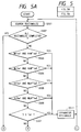
- Fig. 5 is comprised of Figs. 5A and 5B showing flowcharts of an attribute detecting process for detecting attributes of a separator and the like by a size of rectangle;
- Fig. 6 is a diagram showing the division by a density D and an area S of the attributes of a rectangle (area);
- Fig. 7 is a flowchart showing processes of a type-setting direction detector;
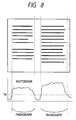
- Fig. 8 is a diagram showing an example of a paragraph detecting process;
- Fig. 9 is a flowchart showing processes of a headline detector;
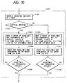
- Fig. 10 is a flowchart showing processes of an ordering unit;
- Fig. 11 is a flowchart showing a process for ordering a headline surrounded by a body which is executed by the ordering unit;
- Fig. 12 is a flowchart showing a process for ordering a headline surrounded by a body which is executed by the ordering unit;
- Fig. 13 is a flowchart showing a process for ordering a headline surrounded by a body which is executed by the ordering unit;
- Fig. 14 is a diagram showing an example of an input original;
- Fig. 15 is a diagram showing headlines and body paragraphs which were extracted by area dividing means;
- Fig. 16 is a diagram showing a state in which the headline surrounded by the body paragraphs was ordered by the ordering means;
- Fig. 17 is a diagram showing a state in which the headlines and a part of the body paragraphs were ordered by the ordering means;
- Fig. 18 is a diagram showing a state in which all of the headlines and body paragraphs were ordered by the ordering means;
- Fig. 19 is a diagram showing an overlap degree of the paragraphs;
- Fig. 20 is a diagram showing a state of judgment regarding whether a body paragraph exists in the upper, lower, left, or right direction of a notice headline or the like;
- Fig. 21 is a diagram showing a state of obtaining a notice point locating at a position that is α % of the height and β % of the width from the left upper corner of the notice headline;
- Fig. 22 is a diagram showing a state of judgment regarding whether a body paragraph exists in the upper, lower, left, or right direction of the notice headline or the like;
- Fig. 23 is a diagram showing an overlap degree of the paragraphs in the vertical direction;
- Fig. 24 is a diagram showing an overlap degree of the paragraphs in the horizontal direction;
- Fig. 25 is a flowchart showing image processes for deciding a table area in the image processing apparatus;
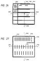
- Fig. 26 is a diagram showing a table and rectangles showing areas of the table;
- Fig. 27 is a diagram showing deformed separators and rectangles showing areas of the deformed separators;
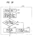
- Fig. 28 is a flowchart showing an example of processes of a table area identifier;
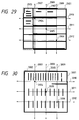
- Fig. 29 is a diagram showing a table and rectangles showing areas of the table;
- Fig. 30 is a diagram showing deformed separators and rectangles showing areas of the deformed separators;
- Fig. 31 is a flowchart showing an example of processes of the table area identifier;
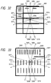
- Fig. 32 is a diagram showing a table and rectangles showing areas of the table;
- Fig. 33 is a diagram showing deformed separators and rectangles showing areas of the deformed separators;
- Fig. 34 is a flowchart showing an example of processes of the table area identifier;
- Fig. 35 is a diagram showing a table and rectangles showing areas of the table;
- Fig. 36 is a flowchart showing an example of processes of the table area identifier;
- Fig. 37 is a flowchart showing an example of processes of the table area identifier;
- Fig. 38 is a flowchart showing an example of processes of the table area identifier;
- Fig. 39 is a flowchart showing an example of processes of the table area identifier;
- Fig. 40 is a flowchart showing an example of processes of the table area identifier;
- Fig. 41 is a block diagram showing a construction of an image processing apparatus for discriminating and obtaining the type-setting direction;
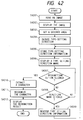
- Fig. 42 is a flowchart showing a flow of a type-setting direction judging process;
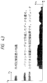
- Fig. 43 is a diagram for explaining projection components of a character image;
- Fig. 44 is a diagram showing an example of display of image data onto a display;
- Fig. 45 is a diagram showing a display example of a type-setting direction mark;
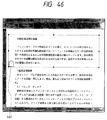
- Fig. 46 is a diagram showing a display example of a type-setting direction mark; and
- Fig. 47 is a flowchart for a procedure to execute image processes by deciding the type-setting direction in a conventional apparatus.
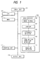
- Fig. 1 is a block diagram showing a construction of an image processing apparatus of the embodiment.
- In the diagram,
reference numeral 101 denotes an input unit of image data for inputting image data which is read by a scanner or image data which is transmitted from a host computer; 102 a central processing unit (CPU) for executing a control of the apparatus in accordance with control programs stored in a memory unit (MEM) 103 and arithmetic operations of a process of each section; and 103 the memory unit for storing the control programs for processes shown in flowcharts, which will be explained hereinlater, and various kinds of data. Thememory unit 103 includes an ROM and an RAM.Reference numeral 104 denotes an output unit for outputting the result of the arithmetic operating process, the result of the image process, and the image data; 105 an area divider for executing a whole area dividing process; 106 an image thinner for thinning out the input image; 107 a labeler for labeling pixels which were thinned out and also for making initial rectangle data; 108 an attribute detector for detecting attributes in an area of a separator, table, figure, or the like; 109 a type-setting direction detector for detecting the type-setting direction of sentences indicative of the vertical writing, horizontal writing, or the like; 110 a headline detector for detecting a headline; and 111 an ordering unit for ordering the paragraphs and headlines of sentences. - Fig. 2 is a flowchart showing image processes in the image processing apparatus of the embodiment. A control program to execute the image processes is stored in the
memory unit 103 and executed by theCPU 102. - An original image is first inputted from the
image input unit 101. - In the
image thinner 106, subsequently, the OR of m dots (in the vertical direction) x n dots (in the horizontal direction) is got for the original image and (m x n) pixels are newly thinned out to one pixel and the image data after completion of the thinning process is stored into thememory unit 103. - When a black pixel of at least one dot exists in the (m x n) pixels in the original image, the thinned image becomes black.
- The
labeler 107 executes processes for adding labels to the black pixels of the thinned image in thememory unit 103 every row, for adding the same label to the pixels which are continuous in the vertical, horizontal, or oblique direction, and for simultaneously tracing a rectangle. - In case of an example shown in Fig. 3, a
label 1 is added to a pixel A which is first detected, coordinates (Xa, Ya) of the pixel A are assumed to an initial and terminal points of the rectangle as thelabel 1, and the number of pixels is set to 1. Thesame label 1 as that of the pixel is added to a rectangle label for distinguishing a rectangle and the above data is stored as rectangle data (Fig. 4) into thememory unit 103. After the label data of the pixel A was stored, a searching operation for labeling is executed in the X direction. In Fig. 3, since the pixel adjacent to the pixel A is a white pixel, a next black pixel B is labeled. - A
label 2 which can be distinguished from the pixel A is added to the pixel B in which pixels which are continuous in the left direction don't exist (since a row which is at present being processed is the first row, there is no pixel that is continuous from the upper position). Coordinates (Xb, Yb) of the pixel B are assumed to initial and terminal points of the rectangle and the number of pixels is set to 1. Thesame label 2 as that of the pixel is added to the rectangle label for distinguishing the rectangle and the above data is also stored as rectangle data (Fig. 4) into thememory unit 103. - In a manner similar to the above, after completion of the labeling of the first row, the processing routine advances to the second row.
- A first black pixel C which is found out by the searching operation for labeling of the second row is continuous with the pixel A of the
label 1 from the upper position. Therefore, thesame pixel label 1 as that of the pixel A is added to the black pixel C. "1" corresponding to the number of pixels of the pixel C is added to the number of pixels for the rectangle data of therectangle label 1, so that the total number of pixels is equal to 2 and the rectangle label is held to 1 without being changed. Only the terminal point of the rectangle coordinates is updated from (Xa, Ya) to (Xa, Yc) (the coordinates of the initial point are not changed). - Since a next pixel D is continuous with the pixel C from the left position, the
same label 1 as that of the pixel C is added. "1" is added to the number of pixels for the rectangle data of therectangle label 1, so that the total number of pixels is equal to 3. The rectangle label is held to 1 without being changed. Only the terminal point of the rectangle coordinates is updated from (Xa, Yc) to (Xd, Yc) (the Y coordinate of the terminal point is not changed). - In this instance, the pixel D is also continuous with the pixel B in the oblique direction and is continuous with the pixel C. Therefore, the label of the pixel B is changed from the
label 2 to thesame label 1 as that of the pixel D. The number of pixels of therectangle label 2 is added to the number of pixels of the rectangle data of therectangle label 1, so that the total number of pixels is equal to 4. The rectangle label is held to 1 without being changed. The X and Y coordinates of only the terminal point of the rectangle coordinates are updated from (Xd, Yc) to (Xb, Yd) as maximum values of four points of A to D. With respect to the rectangle data of therectangle label 2, the rectangle label is set to 0, thereby invalidating. - After the processes of the second row were finished as mentioned above, the processing routine advances to the third row.
- Since the first pixel E of the third row is obliquely continuous with the pixel C, the
same pixel label 1 as that of the pixel C is added. "1" is added to the number of pixels for the rectangle data of therectangle label 1, so that the total number of pixels is equal to 5. The rectangle label is held to 1 without being changed. The initial point of the rectangle coordinates is updated from (Xa, Ya) to the minimum value (Xe, Ya) of five points and the terminal point is updated from (Xb, Yd) to the maximum value (Xb, Ye) of five points. - The labeling and the tracing of the rectangle are executed hereinbelow in a manner similar to the above method.
- In the
attribute detector 108, after completion of the labeling and the tracing of the rectangle, the attributes of the rectangles such as rectangle corresponding to the body, rectangle corresponding to the figure, photograph, table, or the like, rectangle corresponding to the separator, and the like are distinguished by using a width W of rectangle, a height H, an area S, and the number of pixels for the area, namely, a pixel density D (those values of W, H, S, and D can be easily obtained by calculating by using the number of pixels of the rectangle data, the initial and terminal points, and the coordinates). - The process to detect the attributes in step S204 will now be described in detail with reference to a flowchart of Figs. 5A and 5B.
- After the rectangle was searched (step S502) by the labeling process (step S203), the processing routine advances to processes such that the attributes of each rectangle are judged by using the data stored in the
memory unit 103 and the attribute information is set to a rectangle label as shown in Fig. 4 and the data stored in thememory unit 103 is changed. When the width W which is obtained from the coordinates of the initial and terminal points of the rectangle is equal to or less than a threshold value Tw₁ and the height H is equal to or larger than a value that is twice as large as a threshold value Tw of the width W (step S503) or when the width W is larger than the threshold value Tw₁ and the height H is equal to or larger than a value that is triple as large as the threshold value Tw (step S504), such a rectangle is regarded as a separator which is vertically long and the rectangle label in the rectangle data is changed to -3 and the pixel label constructing the rectangle is held as it is separately from the rectangle label (step S514). - The judgment in which the width and height are exchanged is also executed in a manner similar to the above (steps S505 and S506). The rectangle label of the rectangle data which was judged as a separator which is horizontally long in the above steps is changed to -3.
- As shown in Fig. 6, the rectangle data in which the pixel density D is equal to or smaller than a threshold value Td₁ (step S507) is regarded as a deformed separator such as a hook-shaped separator or the like and the rectangle label is changed to -3 (step S514).
- The rectangle data in which the area S is larger than a threshold value Ts₁ (step S508) is regarded as a table so long as the pixel data D is less than a threshold value Td₂ (step S509 in Fig. 5B), and the rectangle label is changed to -4 (step S515). When the pixel density D is equal to or larger than the threshold value Td₂, the rectangle data is regarded as a figure or photograph and the rectangle label is changed to -5 (step S516 in Fig. 5B).
- The rectangle in which the pixel density D of the rectangle data in which the area S is equal to or less than the threshold value Ts₁ and is equal to or larger than a threshold value Ts₂ (step S510) is equal to or larger than a threshold value Td₃ (step S511) or the rectangle in which both of the width W and the height H are equal to or larger than a threshold value Tw₄ and the pixel density D is equal to or larger than a threshold value Td₅ (step S513) is also regarded as a figure or photograph and the rectangle label is changed to -5.
- Further, when the area S is equal to or less than the threshold value Ts₁ and is equal to or larger than the threshold value Ts₂ (step S510), the rectangle in which the pixel density D is less than a threshold value Td₄ (step S512) is regarded as a table and the rectangle label is changed to -4 (step S515).
- As mentioned above, the rectangle corresponding to the figure, photograph, table, or the like, the rectangle corresponding to the separator, and the like are detected and the remaining rectangles are regarded as bodies and the rectangle label is held to the same pixel label as it is (step S517).
- The type-setting direction of the body is subsequently detected by the type-setting
direction detector 109. In case of horizontally written sentences, the rectangle remaining as a body can easily become a horizontally long rectangle in which the pixels which were thinned out in the horizontal direction. In case of vertically written sentences, the rectangle remaining as a body can easily become a rectangle that is vertically long. - Therefore, the average values (w and h) of the width W and height H of the rectangle of the body are calculated (step S701 in Fig. 7). In the case where the average width w is larger than the average height h, the rectangle is regarded as sentences in which the number of horizontally written sentences is large and the average height h is set to a character size of one character (steps S702 and S703 in Fig. 7). On the contrary, in the case where the average height h is larger than the average width w, the rectangle is regarded as sentences in which the number of vertically written sentences is large and the average height h is set to a character size of one character (steps S702 and S710 in Fig. 7).
- Subsequently, a histogram of a rectangle is obtained in the direction opposite to the type setting direction (step S704 in Fig. 7). The location in which it is equal to or less than a threshold value Tk from the shape of a peripheral distribution is regarded as a paragraph separator (steps S705 and S712 in Fig. 7). A histogram of the rectangle is obtained in the same direction as the type-setting direction every paragraph (steps S708 and S715 in Fig. 7). The length of continuous black pixels is set to a character size of a character in the paragraph from the shape of the peripheral distribution and the length of continuous white pixels is detected as a line pitch (steps S709 and S716 in Fig. 7 and Fig. 8).
- Information to discriminate whether the sentences are the horizontally written sentences or the vertically written sentences is stored into the
memory unit 103 together with the rectangle data. - Subsequently, the
headline detector 110 detects a headline by the type-setting direction and character size. - When considering the case of the vertically written sentences as shown in Fig. 9 as an example, the rectangles in which the width W is larger than the character size w by threshold value Tm₁ times or more (namely, W is larger than (w x Tm₁)) are found out from the body rectangles and are detected as candidates of headline rectangles (step S905 in Fig. 9).
- Further, when the height H of the rectangle is smaller than a value that is Tm₂ times as large as the character size (step S906 in Fig. 9), it is regarded that the horizontally written characters are continuous, so that such a rectangle is set to a headline (step S908 in Fig. 9).
- There is a case where a rectangle to which the characters of the body are combined is included in the rectangle which is decided as a headline from the size of rectangle as mentioned above. Therefore, the rectangle in which a distance DBH between the body rectangle and the headline rectangle is shorter than a threshold value T₁ (step S907 in Fig. 9) is corrected from the headline to the body (step S909 in Fig. 9).
- Further, among the body rectangles which remain by the above processes, the rectangle in which none of the body rectangle and the headline rectangle exists in the range of the character size w is set to a headline as an isolated rectangle (steps S910 to S913 in Fig. 9).
- The headlines and body paragraphs are subsequently ordered by the
ordering unit 111. - The ordering process will now be described in detail hereinbelow. Fig. 10 is a detailed flowchart about step S207. First, a check is made to see if there is a headline enclosed by the body or not. If YES, such a headline is first ordered (step S1001). The process in step S1001 will be explained in detail hereinlater with reference to Fig. 11.
- After that, a check is made to see if the sentences are the vertically written sentences or the horizontally written sentences (step S1002) by using the result of the detection of the type-setting direction (step S205) mentioned above. In case of the vertical writing, the headlines and paragraphs locating at almost the same position in the horizontal direction as that of the top area among the headlines and paragraphs which are not yet ordered are collected into the same group (step S1003). When the headlines and paragraphs which belong to the same height are determined, they are sequentially arranged from the right and are ordered (step S1004). After that, when all of the headlines and paragraphs are ordered, step S207 is finished and step S208 follows (step S1005). When there are any other headlines and paragraphs which are not ordered yet, the processing routine is returned to step S1003 and they are ordered in a manner similar to that mentioned above (step S1005).
- When it is likewise judged in step S1002 that the writing direction is the horizontal writing, the headlines and paragraphs which are located at almost the same position in the vertical direction as that of the leftmost area among the headlines and paragraphs which are not ordered are collected into the same group (step S1006). When the headlines and paragraphs which belong to the same group are determined, they are sequentially arranged from the top and ordered (step S1007). When all of the headlines and paragraphs are ordered as mentioned above, step S207 is finished and step S208 follows (step S1008). When there are any other headlines and paragraphs which are not yet ordered, the processing routine is returned to step S1006 and they are likewise ordered (step S1008).
- Explanation will now be made by using an embodiment. Fig. 14 shows an
input original 1401. Fig. 15 shows headlines and body paragraphs which were taken out from the input original 1401 by the area dividing means (steps S202 to S206) mentioned above. In Fig. 15,reference numeral 1501 denotes a whole state of the headlines and body paragraphs corresponding to the input original 1401.Regions Regions 1504 to 1507 shown by broken lines indicate body paragraphs. Fig. 16 shows a state in which it is judged in step S1001 that theheadline 1503 is enclosed by the body, so that No. 1 is ordered to theheadline 1503. It is also possible to construct in a manner such that the data at each stage in Figs. 14 to 16 is output from theoutput unit 104 and is displayed and is confirmed by the operator and the wrong portion is corrected and correct data is again input. - When the vertical writing is judged in step S1002, step S1003 follows. In step S1003, the headline or body paragraph locating at the highest position is first fetched from among the headlines and body paragraphs which are not ordered. In Fig. 16, the
body paragraph 1504 is located at the highest position. Subsequently, the headlines and body paragraphs which belong to the same group as that of thebody paragraph 1504 are taken out. First, a check is made to see if thebody paragraph 1504 and theheadline 1502 belong to the same group or not. Fig. 19 is a diagram for explaining such a judging process. In Fig. 19, reference numerals H1502 and H1504 denote heights of theheadline 1502 andbody paragraph 1504, respectively. H0 indicates an overlap in the horizontal direction of thebody paragraph 1504 andheadline 1502. In the example, H0 = H1502. On the basis of those values, the judgment about the same group is executed as follows. When the following relation


is satisfied, it is regarded that the two areas belong to the same group. The threshold value γ lies within a range from 0.0 to 1.0 and is set to γ = 0.8 here. - In the example shown in Fig. 19, since

it is judged that thebody paragraph 1504 andheadline 1502 belong to the same group. By similarly executing discriminations about the same group with respect to thebody paragraph 1504 and thebody paragraphs 1505 to 1507, it is known that they don't belong to the same group, so that step S1003 is finished. - It step S1004, the
headline 1502 and thebody paragraph 1504 which were judged so that they belong to the same group in step S1003 are sequentially ordered from the right. The points at the right upper corners are compared and No. 2 is ordered to theheadline 1502 placed on the rightmost side. No. 3 is subsequently ordered to thebody paragraph 1504. The points to be compared are not limited to the points at the right upper corners but centers of gravity or other points can be also used so long as it is possible to judge with respect to which area is located on the right side. Fig. 17 shows a state in which No. 2 is ordered to theheadline 1502 and No. 3 is ordered to thebody paragraph 1504 sequentially in accordance with the order from the right side in step S1004. Since thebody paragraphs 1505 to 1507 are not ordered yet, the processing routine is returned from step S1005 to step S1003 and the processes are continued. - In step S1003, the
body paragraphs 1505 to 1507 are set into the same group. In step S1004, No. 4 is ordered to thebody paragraph 1505, No. 5 is ordered to thebody paragraph 1506, and No. 6 is ordered to thebody paragraph 1507 sequentially in accordance with the order from the right side. - When all of the headlines and body paragraphs are ordered, the processing routine advances from step S1005 to the next step S208. Fig. 18 shows a state in which step S207 is finished and all of the headlines and body paragraphs have been ordered.
- The process in step S1001 will now be described in detail. Fig. 11 is a flowchart showing the process in step S1001.
- In the first step S1101, an attention is paid to one headline area and its center is obtained. In the example of the input original 1401, as shown in Fig. 15, there are two headline areas of the
headlines first headline 1503. Since the area is a rectangle, the center is located at a position at which each of the width and height is divided into two parts. Such a center is shown byreference numeral 2001 in Fig. 20. - In step S1102, line segments are extended in the upper, lower, left, and right directions from the
center 2001 and a check is made to see if they intersect with the body paragraphs or not. In Fig. 20, the line segment which is extended in the upper direction from thecenter 2001 is shown by aline segment 2002. Likewise, the line segment extending in the lower direction is shown byreference numeral 2003, the line segment extending in the left direction is shown by 2004, and the line segment exteding in the right direction is indicated by 2005. As will be obviously understood from Fig. 20, theline segment 2002 intersects with thebody paragraph 1504. Similarly, theline segment 2003 intersects with thebody paragraph 1506, theline segment 2005 intersects with thebody paragraph 1505, and theline segment 2004 intersects with thebody paragraph 1507. - In step S1103, since the line segments extending from the center in at least three of the upper, lower, left, and right directions intersect with the body paragraphs, the processing routine advances to step S1104. If the line segments extending from the center in only two or less of the upper, lower, left, and right directions intersect with the body paragraphs, the processing routine advances to step S1105.
- In step S1104, the notice headline is ordered. Since none of the headlines is ordered yet, No. 1 is ordered to the
headline 1503. - In step S1105, a check is made to see if all of the headlines are judged or not. When there are any other headlines, the processing routine is returned to step S1101 and processes similar to those mentioned above are exectued. When all of the headlines are judged, step S1002 follows. In the example of the input original 1401, since the
headline 1502 is not yet discriminated, the processing routine is returned to step S1101. - In substantially the same manner as the case of the
headline 1503, the center is obtained (step S1101), the line segments are extended in the upper, lower, left, and right directions from the center, and a check is made to see if they intersect with the body paragraphs or not (step S1102). As will be also obviously understood from Fig. 15, since no body paragraph exists in the upper and right directions of theheadline 1502, the line segments in the upper and right directions extending from the center of theheadline 1502 don't intersect with the body paragraphs. Therefore, the processing routine advances from step S1103 to step S1105. Namely, theheadline 1502 is not ordered. Since all of the headlines have already been judged in step S1105, all of the processes in step S1001 are finished and step S1002 follows. Fig. 16 shows the result until this stage. - As mentioned above, all of the headlines and body paragraphs are ordered in step S207. Fig. 18 shows a state in which the processes until step S207 have been finished in the example of the input original 1401.
- Finally, the rectangle data of various kinds of areas obtained as mentioned above is output from the
output unit 104 together with the image data. - Fig. 12 is a flowchart showing processes such that in the process for ordering the headline enclosed by the body, and arbitrary point in the notice headline is used in place of the
center 2001 in the judgment regarding whether the rectangle relates to the headline enclosed by the body or not in the example described before (flowchart in Fig. 11). Explanation will now be made hereinbelow with reference to the flowchart shown in Fig. 12. - In the first step S1201, an attention is paid to one headline area and an arbitrary point in the notice headline is obtained. It is now assumed that an arbitrary point is set to the position corresponding to α % of the height and β % of the width from the left upper corner. The value of each of α and β lies within a range from 0 to 100 % and predetermined values are held in the RAM. In the example of the input original 1401, as shown in Fig. 15, there are two areas of the
headlines headline 1503 here. An arbitrary point in theheadline 1503 is fetched and is used as a notice point. Fig. 21 is a diagram for explaining a state in which an arbitrary point locating at the position corresponding to α % of the height and β % of the width from the left upper corner is obtained. In Fig. 21, H denotes the height ofheadline 1503, Hα indicates α % of the height from the left upper corner, W shows the width of theheadline 1503, and Wβ indicates β % of the width from the left upper corner. Anotice point 2101 is obtained as mentioned above. It is now assumed that α is equal to 40 % and β is equal to 25 %. - In step S1202, line segments are subsequently extended in the upper, lower, left, and right directions from the
notice point 2101 and a check is made to see if they intersect with the body paragraphs or not, respectively. In Fig. 22, the line segment extending in the upper direction from thenotice point 2101 is shown by aline segment 2201. Similarly, the line segment extending in the lower direction is shown by 2202, the line segment extending in the left direction is shown by 2203, and the line segment extending in the right direction is shown by 2204. As will be obviously understood from Fig. 22, theline segment 2201 intersects with thebody paragraph 1504. Likewise, theline segment 2202 intersects with thebody paragraph 1506, theline segment 2204 intersects with thebody paragraph 1505, and theline segment 2203 intersects with thebody paragraph 1507. - In step S1203, since the line segments extending from the
notice point 2101 intersect in at least three of the upper, lower, left, and right directions, the processing routine advances to step S1204. If the line segments extending from thenotice point 2101 in only two of the upper, lower, left, and right directions intersect with the body paragraph, step S1205 follows. - In step S1204, the notice headline is ordered. Since none of the headlines is ordered here, No. 1 is ordered to the
headline 1503. - A check is now made to see if all of the headlines have been judged or not in step S1205. If there are any other headlines, the processing routine is returned to step S1201 and processes similar to those mentioned above are executed. After all of the headlines were judged, step S1002 follows. In the example of the input original 1401, since the
headline 1502 is not yet judged, the processing routine is returned to step S1201. - In substantially the same manner as the case of the
headline 1503, a notice point is obtained (step S1201), line segments are extended in the upper, lower, left, and right directions from the notice point, and a check is made to see if they intersect with the body paragraphs or not (step S1202). As will be also obviously understood from Fig. 15, since no body paragraph exists in the upper and right directions of theheadline 1502, the line segments in the upper and right directions extending from the center of theheadline 1502 don't intersect with the body paragraphs. Therefore, the processing routine advances from step S1203 to step S1205. Namely, theheadline 1502 is not ordered. In step S1205, since all of the headlines have been judged, all of the processes in step S1001 are finished and step S1002 follows. Fig. 16 shows the results until this stage. - As mentioned above, all of the headlines and body paragraphs are ordered in step S207. Fig. 18 shows a state in which the processes until step S207 have been finished in the example of Fig. 14.
- The processes other than step S1001 are similar to those in the first embodiment. A construction of an image processing apparatus in the second embodiment is similar to that of the first embodiment shown in Fig. 1. By the above description, operation and effects similar to those in the first embodiment mentioned above are obtained.
- Fig. 13 is a flowchart showing processes in which the processing contents in steps S1305 and S1306 are further added to the process to order the headline enclosed by the body in step S1001 in Fig. 10 and in which overlap degrees with the body paragraphs in the upper, lower, left, and right directions of the notice headline are discriminated and, when the body paragraphs in which the overlap degree is equal to or larger than a threshold value exist in three or more directions, the notice headline is ordered.
- Explanation will now be made hereinbelow with reference to a flowchart shown in Fig. 13.
- In the first step S1301, an attention is paid to one headline area and its center is obtained. In the example of the input original 1401, as shown in Fig. 15 there are two headline areas of the
headlines headline 1503. Since the area is a rectangle, the center is located at a position at which each of the width and height is divided into two equal parts. Such a center is shown byreference numeral 2001 in Fig. 20. - In step S1302, line segments are extended in the upper, lower, left, and right directions from the
center 2001 and a check is made to see if they intersect with the body paragraphs or not. In Fig. 20, the line segment extending in the upper direction from thecenter 2001 is shown by theline segment 2002. Similarly, the line segment extending in the lower direction is shown by 2003, the line segment extending in the left direction is shown by 2004, and the line segment extending in the right direction is shown by 2005. As will be obviously understood from Fig. 20, theline segment 2002 intersects with thebody paragraph 1504. Likewise, theline segment 2003 intersects with thebody paragraph 1506, theline segment 2005 intersects with thebody paragraph 1505, and theline segment 2004 intersects with thebody paragraph 1507. - In step S1303, since the line segments extending from the center intersect with the body paragraphs in three or more of the upper, lower, left, and right directions as mentioned above, the processing routine advances to step S1304. If the line segments extending from the center intersect with the body paragraphs in only two or less of the upper, lower, left, and right directions, step S1307 follows.
- In step S1304, with respect to the body paragraphs locating in the upper and lower directions of the headline, overlap degrees in the vertical direction with the headline are examined. Likewise, with regard to the body paragraphs locating in the left and right directions, overlap degrees in the horizontal direction with the headline are judged, respectively. When the overlap degree with the
body paragraph 1504 locating in the upper direction of theheadline 1503 is judged, as shown in Fig. 23, an overlap between the width W1503 of theheadline 1503 and the width W1504 of thebody paragraph 1504 is indicated by W0. In the example, W0 = W1503. On the basis of those values, the overlap degrees are judged as follows in step S1305. When the following relation


is satisfied, the overlap degree is equal to or larger than the threshold value. The threshold value γ lies within a range from 0.0 to 1.0 and is set to γ = 0.8 here. - In the example shown in Fig. 23, since

the overlap degree between thebody paragraph 1504 and theheadline 1503 is equal to or larger than the threshold value. - Similarly, the overlap degree between the
headline 1503 and thebody paragraph 1506 locating under theheadline 1503 is also equal to or larger than the threshold value. In a manner similar to the above, the overlap degree between theheadline 1503 and thebody paragraph 1507 locating on the left side of theheadline 1503 is judged. As shown in Fig. 24, the height ofheadline 1503 is shown by H1503, the height ofbody paragraph 1507 is shown by H1507, and the overlap degree between theheadline 1507 and thebody paragraph 1507 is shown by H0. In this example, H0 = H1503. In step S1305, the overlap degrees are judged as follows on the basis of those values. When the following relation


is satisfied, the overlap degree is equal to or larger than the threshold value. However, the threshold value lies within a range from 0.0 to 1.0 and is set to 0.8 here. - In the example shown in Fig. 24, since

the overlap degree between thebody paragraph 1507 and theheadline 1503 is equal to or larger than the threshold value. Similarly, the overlap degree between theheadline 1503 and thebody paragraph 1505 locating on the right side thereof is also equal to or larger than the threshold value. - As mentioned above, in the example of Fig. 14, since the body paragraphs in which the overlap degree is equal to or larger than the threshold value exist in three or more directions, the processing routine advances to step S1306.
- In step S1306, the notice headline is ordered. Since none of the headlines is yet ordered here, No. 1 is ordered to the
headline 1503. A check is made to see if all of the headlines have been checked or not. When there are any other headlines, the processing routine is returned to step S1301 and processes similar to those mentioned above are executed. After all of the headlines were checked, step S1002 follows. - In the example of the input original 1401, since the
headline 1502 is not yet checked, the processing routine is returned to step S1301. In substantially the same manner as the case of theheadline 1503, the center is obtained (step S1301), line segments are extended in the upper, lower, left, and right directions from the center, and a check is made to see if they intersect with the body paragraphs or not, respectively (step S1302). As will be also obviously understood from Fig. 15, since no body paragraph exists in the upper and right directions of theheadline 1502, the line segments extending in the upper and right directions from the center of theheadline 1502 don't intersect with the body paragraphs. Therefore, the processing routine advances from step S1303 to step S1307. Namely, theheadline 1502 is not ordered. - In step S1307, since all of the headlines were checked, all of the processes in step S1001 are finished and step S1002 follows. Fig. 16 shows the results until this stage.
- As mentioned above, all of the headlines and body paragraphs are ordered in step S207. Fig. 18 shows a state after the processes until step S207 were finished in the example of Fig. 14.
- In the embodiment, explanation will now be made with respect to an example in which radial line segments are extended from the rectangle whose attribute was determined to be a table and a table area is identified from the number of intersections with the table frame. A construction of an apparatus of the embodiment is similar to that of the embodiment.
- Fig. 2 is a flowchart showing image processes in the image processing apparatus of the embodiment. Control programs for executing the image processes have been stored in the
memory unit 103. In the flowchart, the same processing steps as those in theembodiment 1 are designated by the same reference numerals and their descriptions are omitted here. - A table area is identified by a table area identifier 112. Fig. 28 is a flowchart for explaining in detail a process for identifying a table area in step S209.
- Fig. 26 is a diagram for explaining step S209 in case of a table.
Reference numeral 2601 denotes a rectangle area; 2602 a table frame; 2603 a character or the like in the table; 2604 a center (notice point) of therectangle area 2601; and 2605 to 2608 line segments extending in the upper, lower, left, and right directions from thenotice point 2604, respectively. - Similarly, Fig. 27 is a diagram for explaining step S209 in case of a deformed
separator Reference numeral 2701 denotes a rectangle area; 2702 a deformed separator; 2703 a character or the like in the deformed separator; 2704 a center (notice point) of therectangle area 2701; and 2705 to 2708 line segments extending in the upper, lower, left, and right directions from thenotice point 2704, respectively. - Explanation will now be made hereinbelow with respect to the case of a table with reference to a flowchart of Fig. 28 and Fig. 26.
- In the embodiment, it is assumed that a center is set to one arbitrary notice point in the rectangle area which was decided to be a table and total four line segments are extended one by one in the upper, lower, left, and right directions. There is used table identifying means for identifying the rectangle area as a table in the case where one (or more) notice point such that at least one of the line segments extending in the upper, lower, left, and right directions intersects with the table frame three or more times exists or for identifying the rectangle area as a deformed separator in the case other than the above case.
- The center of the rectangle area is first obtained and set into the notice point in step S2801.
- The position at which each of the width and height is divided into two equal parts is set to the center and the
notice point 2604 is obtained. - In step S2802, line segments are subsequently extended in the upper, lower, left, and right directions from the
notice point 2604 and the number of intersections with the table frame is counted. In Fig. 26, the line segment extending in the upper direction from thenotice point 2604 is indicated by aline segment 2605. Similarly, the line segment extending in the lower direction is shown by 2606, the line segment extending in the left direction is shown by 2607, and the line segment extending in the right direction is shown by 2608. - The number of intersections with the table frame is equal to three in case of the
line segment 2605, three in case of theline segment 2606, two in case of theline segment 2607, and one in case of theline segment 2608. - A check is made in step S2803 to see if there are line segments which intersect with the table frame three or more times among the line segments extending in the upper, lower, left, and right directions or not. Since the
line segments - In step S2804, the rectangle area is identified as a table area and step S210 follows.
- Explanation will now be made with respect to the case of the deformed separator with reference to a flowchart of Fig. 28 and Fig. 27.
- First, in step S2801, the center of rectangle area is obtained and set to a notice point. The position which each of the width and height is divided into two equal parts is set to the center and a
notice point 2704 is obtained. - In step S2802, line segments are extended in the upper, lower, left, and right directions from the
notice point 2704 and the number of intersections with the table frame (deformed separator) is counted. In Fig. 27, the line segment extending in the upper direction from thenotice point 2704 is shown by 2705. Similarly, the line segment extending in the lower direction is indicated by 2706, the line segment extending in the left direction is shown by 2707, and the line segment extending in the right direction is shown by 2708. - The number of intersections with the table frame is equal to one in case of the
line segment 2705, one in case of theline segment 2706, one in case of theline segment 2707, and one in case of theline segment 2708. - In step S2803, a check is made to see if there are line segments which intersect with the table frame three or more times among the line segments extending in the upper, lower, left, and right directions or not. Since none of the line segments intersects with the table frame three or more times, step S2805 follows.
- In step S2805, the rectangle area is identified as a deformed separator area and step S205 follows.
- Finally, the rectangle data of various kinds of areas obtained as mentioned above is output from the
output unit 104 together with the image data. - Fig. 31 is a flowchart for explaining in detail an example in which a plurality of notice points are set in the rectangle area in t he process for identifying the table area in step S209.
- Fig. 29 is a diagram for explaining step S209 in case of a table.
Reference numeral 2901 denotes a rectangle area; 2902 a table frame; 2903 a character or the like in the table; 2904 to 2906 arbitrary notice points in the rectangle area; and 2907 to 2912 line segments extending in the upper, lower, left, and right directions from the notice points 2904, 2905, and 2906, respectively. - Similarly, Fig. 30 is a diagram for explaining step S209 in case of a deformed separator.
Reference numeral 3001 denotes a rectangle area; 3002 a deformed separator; 3003 a character or the like in the deformed separator; 3004 to 3006 arbitrary notice points in the rectangle area; and 3007 to 3012 line segments extending in the upper, lower, left, and right directions from the notice points 3004, 3005, and 3006, respectively. - Explanation will now be made hereinbelow with respect to the case of a table with reference to Fig. 29 and a flowchart of Fig. 31.
- In the embodiment, three arbitrary notice points in the rectangle area which was justed as a table are obtained and total 12 line segments are extended. Namely, it is assumed that total four line segments are extended one by one in the upper, lower, left, and right directions for every notice point, respectively. There is used table identifying means for identifying the rectangle area as a table in the case where two or more notice points such that at least one of the line segments extending in the upper, lower, left, and right directions intersects with the table frame three or more times exist and for identifying the rectangle area as a deformed separator in the case other than the above case.
- In the first step S3101, three notice points are set in the rectangle area. The point at which each of the width and height is divided into 1/4 is set to the
target point 2904. The point at which each of the width and height is divided into 1/2 from the point at the left upper corner is set to thenotice point 2905. The point at which each of the width and height is divided into 3/4 is set to thenotice point 2906. - The number (NTA) of table area identified notice points is set to NTA = 0 in the next step S3102.
- In step S3103, line segments are extended in the upper, lower, left, and right directions from the
notice point 2904 and the number of intersections with the table frame is counted, respectively. In Fig. 29, the line segments extending in the upper and lower directions from thenotice point 2904 are shown by theline segment 2907. The line segments extending in the left and right directions are shown by theline segment 2910. - The number of intersections with the table frame is equal to two in case of the line segment extending in the upper direction, four in case of the line segment extending in the lower direction, two in case of the line segment extending in the left direction, and one in case of the line segment extending in the right direction.
- In step S3104, a check is made to see if there are line segments which intersect with the table frame three or more times among the line segments extending in the upper, lower, left, and right directions or not. Since the line segment extending in the lower direction intersects with the table frame three or more times, the processing routine advances to step S3105. If there is no line segment which intersects with the table frame three or more times, step S3106 follows.
- In step S3105, "1" is added to the number (NTA) of table area identified notice points and step S3106 follows.
(the number of table area identified notice points) = 0 + 1 = 1
In step S3106, a check is made to see if the processes have been executed for all of the notice points or not. Since the notice points 2905 and 2906 remain, the processing routine is returned to step S3103. Processes similar to those for thenotice point 2904 are also executed to the notice points 2905 and 2906. As will be obviously understood from Fig. 29, when the processes for all of the notice points are finished,
(the number of table area identified notice points) = 3
Since the processes regarding all of the notice points are finished, step S3107 follows. - In step S3107, a check is made to see if (the number of table area identified notice points) is equal to or larger than 2 or not. Since it is equal to or larger than 2, step S3108 follows.
- In step S3108, the rectangle area is identified as a table area and step S205 follows.
- Explanation will now be made with respect to the case of a deformed separator with reference to Fig. 30 and a flowchart of Fig. 31.
- In the first step S3101, three notice points are set in the rectangle area. The point at which each of the width and height is divided into 1/4 from the point at the left upper corner is set to the
notice point 3004, the point at which each of the width and height is divided into 1/2 is set to thenotice point 3005, and the point at which each of the width and height is divided into 3/4 is set to thenotice point 3006. - In step S3102, (the number of table area identified notice points) is set to 0.
- In step S3103, line segments are extended in the upper, lower, left, and right directions from the
notice point 3004 and the number of intersections with the table frame is counted. In Fig. 31, the line segments extending in the upper and lower directions from thenotice point 3004 are shown by aline segment 3007. The line segments extending in the left and right directions are shown by aline segment 3010. - The number of intersections with the table frame is equal to one in case of the line segment extending in the upper direction, one in case of the line segment extending in the lower direction, one in case of the line segment extending in the left direction, and one in case of the line segment extending in the right direction, respectively.
- In step S3104, a check is made to see if there are line segments which intersect with the table frame three or more times among the line segments extending in the upper, lower, left, and right directions or not. Since none of the line segments extending in the upper, lower, left, and right directions intersects the table frame three or more times, step S3106 follows.
- In step S3106, a check is made to see if the processes have been executed for all of the notice points or not. Since the notice points 3005 and 3006 remain, the processing routine is returned to step S3103. Processes similar to those in the
notice point 3004 are also executed for the notice points 3005 and 3006. As will be obviously understood from Fig. 30, when the processes are finished for all of the notice points,
(the number of table area identified notice points) = 0
Since the processes about all of the notice points have been finished, step S3107 follows. - In step S3107, a check is made to see if (the number of table area identified notice points) is equal to or larger than 2 or not. Since it is smaller than 2, step S3109 follows.
- In step S3109, the rectangle area is identified as a deformed separator area and step S210 follows.
- Fig. 34 is a flowchart for explaining in detail an example in which a plurality of line segments extending in the upper, lower, left, and right directions are set in the table area identifying process in step S209.
- Fig. 32 is a diagram for explaining step S209 in case of the table.
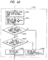
Reference numeral 3201 denotes a rectangle area; 3202 a table frame; 3203 a character or the like in the table; 3204 a center (notice point) in the rectangle area; 3205 to 3207 line segments extending in the upper direction from thenotice point 3204; 3208 to 3210 line segments extending in the lower direction from thenotice point 3204; 3211 to 3213 line segments extending in the left direction from thenotice point 3204; and 3214 to 3216 line segments extending in the right direction from thenotice point 3204. - Similarly, Fig. 33 is a diagram for explaining step S209 in case of a deformed separator.
Reference numeral 3301 denotes a rectangle area; 3302 a deformed separator; 3303 a character or the like in the deformed separator; 3304 a center (notice point) in the rectangle area; 3305 to 3307 line segments extending in the upper direction from thenotice point 3304; 3308 to 3310 line segments extending in the lower direction from thenotice point 3304; 3311 to 3313 line segments extending in the left direction from thenotice point 3304; and 3314 to 3316 line segments extending in the right direction from thenotice point 3304. - Explanation will now be made hereinbelow with respect to the case of a table with reference to Fig. 32 and a flowchart of Fig. 23.
- In the embodiment, it is assumed that a center is set to one arbitrary notice point in the rectangle area which was judged as a table and total 12 line segments are extended, namely, three line segments are extended in each of the upper, lower, left, and right directions, respectively. There is used table identifying means for identifying the rectangle area as a table in the case where one (or more) notice point such that the line segments intersect with the table frame three or more times among the line segments extending in the upper, lower, left, and right directions exists and for identifying the rectangle area as a deformed separator in the case other than the above case.
- In the first step S3401, the center of the rectangle area is obtained and set to a notice point.
- The position at which each of the width and height is divided into 1/2 corresponds to the center and the
notice point 3204 is obtained. - In the next step S3402, total 12 line segments are extended, namely, three line segments are extended in each of the upper, lower, left, and right directions from the
notice point 3204, respectively. The number of intersections with the table frame is counted, respectively. As will be obviously understood from Fig. 32, the number of intersections with the table frame is equal to three in case of each of theline segments line segments line segments line segment 3214, and one in case of each of theline segments - In step S3403, a check is made to see if there are line segments which intersect with the table frame three or more times among the line segments extending in the upper, lower, left, and right directions or not.
- Since the
line segments - In step S3404, the rectangle area is identified as a table area and step S210 follows.
- Explanation will now be made with respect to the case of a deformed separator with reference to Fig. 33 and a flowchart of Fig. 34.
- In the first step S3401, the center of the rectangle area is obtained and set to the notice point.
- The position at which each of the width and height is divided into 1/2 corresponds to the center and the
notice point 3304 is obtained. - In the next step S3402, total 12 line segments are extended, namely, three line segments are extended in each of the upper, lower, left, and right directions from the
notice point 3304. The number of intersections with the table frame is counted, respectively. As will be obviously understood from Fig. 33, the number of intersections with the table frame is equal to one in case of each of theline segments 3305, 3306, and 3307, one in case of each of theline segments line segments line segments - In step S3403, a check is made to see if there are line segments which intersect with the table frame three or more times among the line segments extending in the upper, lower, left, and right directions or not. Since there is no line segments which intersects with the table frame three or more times, step S3405 follows.
- In step S3405, the rectangle area is identified as a deformed separator area and step S210 follows.
- Fig. 36 is a flowchart for explaining in detail the table area identifying process in step S209 and shows an example in which a notice point is obtained out of the table frame in the area rectangle (step S1701).
- Fig. 35 is a diagram for explaining step S209 in case of a table.
Reference numeral 3501 denotes a rectangle area; 3502 a center of therectangle area 3501; 3503 eight points near thecenter 3502; 3504 a left upper point among the eight points near thecenter 3502; 3505 a point just over thecenter 3502 among the eight points near the center 3502 (thepoint 3505 corresponds to the notice point); and 3506 to 3509 line segments extending in the upper, lower, left, and right directions from thenotice point 3505, respectively. A black circle denotes the pixel which belongs to the table frame. A white circle indicates a pixel other than the table frame. - The black pixels constructing a character or the like in the table are omitted here.
- Explanation will now be made hereinbelow with respect to the case of a table with reference to Fig. 35 and a flowchart of Fig. 36.
- In the embodiment, it is now assumed that one arbitrary notice point which doesn't belong to the table frame in the rectangle area which was judged as a table is obtained and total four line segments are extended one by one in the upper, lower, left, and right directions. There is used table identifying means for identifying the rectangle area as a table in the case where one or more notice points such that at least one of the line segments extending in the upper, lower, left, and right directions intersects with the table frame three or more times exist and for identifying the rectangle area as a deformed separator in the case other than the above case.
- In the first step S3601, a notice point other than the table frame is obtained in the rectangle area.
- The center is first obtained as a notice point and a check is made to see if the center belongs to the table frame or not. If NO, the center is set to the notice point. When the center belongs to the table frame, eight points near the center are sequentially clockwise checked from the left upper point. The point which doesn't belong to the table frame is set to the notice point. When such a point is not found out from those eight points, the other points existing on the outside of those eight points are subsequently checked.
- The center is first obtained.
- The position at which each of the width and height is divided into 1/2 corresponds to the center and the
center 3502 is obtained. - A check is now made to see if the center doesn't belong to the table frame or not. As will be obviously understood from Fig. 35, the
center 3502 belongs to the table frame. Since it belongs to the table frame, eight points near the center are examined. First of all, a check is made to see if the leftupper point 3504 of thecenter 3502 belongs to the table frame or not. Thenear point 3504 belongs to the table frame as will be obviously understood from Fig. 35. Subsequently, the next one of the eight near points is checked clockwise. That is, the next point to be examined is thenear point 3505. - As will be obviously understood from Fig. 35, since the
near point 3505 doesn't belong to the table frame, thenear point 3505 is set to the notice point and step S2802 follows. - In step S2582, line segments are extended in the upper, lower, left, and right directions from the
notice point 3505 and the number of intersections with the table frame is counted, respectively. In Fig. 35, the line segment extending in the upper direction from thenotice point 3505 is shown by theline segment 3506. Similarly, the line segment extending in the lower direction is shown by 3507. The line segment extending in the left direction is shown by 3508. The line segment extending in the right direction is shown by 3509. - The number of intersections with the table frame is equal to two in case of the
line segment 3506, three in case of theline segment 3507, two in case of theline segment 3508, and one in case of theline segment 3509. - In step S2803, a check is made to see if there are line segments which intersect with the table frame three or more times among the line segments extending in the upper, lower, left, and right directions or not. Since the
line segment 3507 intersects with the table frame three or more times, step S2805 follows. If there is no line segment which intersects with the table frame three or more times, step S2806 follows. - In step S2805, the rectangle area is identified as a table area and step S210 follows.
- In step S2806, the rectangle area is identified as a deformed separator area and step S210 follows.
- When an image is inputted in step S201, a check is made to see if it is a multi-value image or not. In case of the multi-value image, it is converted into a binary image, so that the area dividing process can be executed even in the case where the input image is a multi-value image such as a color image or the like.
- When the image is inputted in step S201, it is also possible to construct in a manner such that when the number of pixels of the input image is so large as to need a fairly long processing time, by executing an image thinning process for thinning out the image of m dots (in the vertical direction) x n dots (in the horizontal direction) into one pixel, the processing speed can be raise.
- In the detection or the like of the separator in step S203, it is also possible to execute the further detailed classification of the area attributes by distinguishing the rectangle label on the basis of a difference between the vertical/horizontal direction of the separator, a difference the threshold values when the figure, table, or the like is obtained, or the like.
- When the table area is identified in step S209, the table area identifying process can be performed without executing a process such that the number of line segments which are extended in the upper, lower, left, and right directions is equivalently distributed in the upper, lower, left, and right directions.
- On the other hand, in the table area identification in step S209, in the case where there are a plurality of notice points, the table area identifying process can be performed without executing a process such that the number of line segments which are extended in the upper, lower, left, and right directions is equivalently distributed every notice point.
- In the embodiment, explanation will now be made with respect to an example in which radial line segments are extended from the rectangle area which was judged as a table and the table area is identified on the basis of the number of intersections with the table frame and the direction. A construction of an apparatus in the embodiment is similar to that of the
embodiment 1. - A flowchart showing image processes in the image processing apparatus of the embodiment is similar to the flowchart of Fig. 25 described in the
embodiment 2. - A table area is subsequently identified. Fig. 37 is a flowchart for explaining in detail the table area identifying process in step S209. In Fig. 37, processing steps similar to those in Fig. 28 are designated by the same reference numerals and their descriptions are omitted here.
- In the embodiment, it is now assumed that a center is set to one arbitrary notice point in the rectangle area which was judged as a table and total four line segments are extended one by one in the upper, lower, left, and right directions. There is used table identifying means for identifying the rectangle area as a table in the case where one (or more) notice point such that at least one of the line segments extending in the upper and lower directions intersects with the table frame two or more times and at least one of the line segments extending in the left and right directions intersects with the table frame two or more times exists and for identifying the rectangle area as a deformed separator in the case other than such a case.
- In step S3703, a check is made to see if at least one of the line segments extending in the upper and lower directions intersects with the table frame two or more times or not. Since both of the
line segments - In step S3704, a check is made to see if at least one of the line segments extending in the left and right directions intersects with the table frame two or more times or not. Since the
line segment 2605 intersects with the table frame two or more times, step S3705 follows. If there is no line segment which intersects with the table frame two or more times, step S3706 follows. - In step S3705, the rectangle area is identified as a table area and step S210 follows.
- Explanation will now be made with respect to the case of a deformed separator.
- In step S3703, a check is made to see if at least one of the line segments extending in the upper and lower directions intersects with the table frame two or more times or not. Since none of the
line segments - In step S3706, the rectangle area is identified as a deformed separator area and step S210 follows.
- Finally, the rectangle data of various kinds of areas obtained as mentioned above is output from the
output unit 104 together with the image data. - Fig. 38 is a flowchart for explaining in detail an example in which a plurality of notice points are obtained in the rectangle area in the table area identifying process in step S209.
- In the process in Fig. 38, processing steps similar to those in the flowchart of Fig. 31 in the
embodiment 2 are designated by the same reference numerals and their descriptions are omitted here. - Explanation will now be made hereinbelow with respect to the case of a table with reference to Fig. 29 and the flowchart of Fig. 38.
- In this process, it is now assumed that three arbitrary notice points are obtained in the rectangle area which was judged as a table and total 12 line segments are extended, namely, total four line segments are extended one by one in the upper, lower, left, and right directions every notice point, respectively. There is used table identifying means for identifying the rectangle area as a table in the case where two or more notice points such that at least one of the line segments extending in the upper and lower directions intersects with the table frame two or more times and at least one of the line segments extending in the left and right directions intersects with the table frame two or more times exist and for identifying the rectangle area as a deformed separator in the case other than the above case.
- In step S3804, a check is made to see if at least one of the line segments extending in the upper and lower directions intersects with the table frame two or more times or not. Since both of the line segments extending in the upper and lower directions intersect with the table frame two or more times, step S1205 follows. If there is no line segment which intersects with the table frame two or more times, step S3807 follows.
- In step S3805, a check is made to see if at least one of the line segments extending in the left and right directions intersects with the table frame two or more times or not. Since the line segment extending in the left direction intersects with the table frame two or more times, step S3806 follows. If there is no line segment which intersects with the table frame two or more times, step S3807 follows.
- In step S3806, "1" is added to the number of table area identified notice points.
(the number of table area identified notice points) = 0 + 1 = 1
In step S3807, a check is made to see if the processes have been performed for all of the notice points or not. Since the notice points 2905 and 2906 still remain, the processing routine is returned to step S3805. Processes similar to those for thenotice point 2905 are also executed for the notice points 2905 and 2906. As will be obviously understood from Fig. 29, when the processes are finished for all of the notice points,
(the number of table area identified notice points) = 3
Since the processes about all of the notice points have been finished, step S3808 follows. - In step S3808, a check is made to see if (the number of table area identified notice points) is equal to or larger than 2 or not. Since it is equal to or larger than 2, step S3809 follows.
- In step S3809, the rectangle area is identified as a table area and step S210 follows.
- Explanation will now be made with respect to the case of a deformed separator.
- In step S3804, a check is made to see if at least one of the line segments extending in the upper and lower directions intersects with the table frame two or more times or not. Since both of the line segments extending in the upper and lower directions don't intersect the table frame two or more times, step S3807 follows.
- In step S3807, a check is made to see if the processes have been executed for all of the notice points or not. Since the notice points 3005 and 3006 still remain, the processing routine is returned to step S3803. Processes similar to those for the
notice point 3004 are also executed to the notice points 3005 and 3006. As will be obviously understood from Fig. 30, when the processes are finished for all of the notice point,
(the number of table area identified notice points) = 0
Since the processes about all of the notice points have been finished, step S3808 follows. - In step S3808, a check is made to see if (the number of table area identified notice points) is equal to or larger than 2. Since it is not equal to or larger than 2, step S3810 follows.
- In step S3810, the rectangle area is identified as a deformed separator area and step S210 follows.
- Fig. 39 is a flowchart for explaining in detail an example in which a plurality of line segments are extended in the upper, lower, left, and right directions in the table area identifying process in step S209.
- In the process in Fig. 39, processing steps similar to those in the flowchart of Fig. 34 in the
embodiment 2 are designated by the same reference numerals and their descriptions are omitted here. - In step S3903, a check is made to see if there are line segments which intersect with the table frame two or more times among the line segments extending in the upper and lower directions or not. Since all of the line segments intersect with the table frame two or more times, step S3904 follows. If there is no line segment which intersects with the table frame two or more times, step S3906 follows.
- In step S3904, a check is made to see if there are line segments which intersect with the table frame two or more times among the line segments extending in the left and right directions or not. Since the
line segments - In step S3905, the rectangle area is identified as a table area and step S210 follows.
- Explanation will now be made with respect to the case of a deformed separator.
- In step S3905, a check is made to see if there are line segments which intersect with the table frame two or more times among the line segments extending in the upper and lower directions or not. Since there is no line segment which intersects with the table frame two or more times, step S3906 follows.
- In step S3906, the rectangle area is identified as a deformed separator area and step S210 follows.
- Fig. 40 is a flowchart for explaining in detail the table area identifying process in step S209 and shows an example in which a notice point is obtained out of the table frame in the area rectangle (step S3601).
- In the process of Fig. 40, processing steps similar to those shown in the flowchart of Fig. 28 of the
embodiment 2 are designated by the same reference numerals and their descriptions are omitted here. - In the embodiment, it is assumed that one arbitrary notice point which doesn't belong to the table frame in the rectangle area which was judged as a table is obtained and total four line segments are extended one by one in the upper, lower, left, and right directions, respectively. There is used table identifying means for identifying the rectangle area as a table in the case where one or more notice points such that at least one of the line segments extending in the upper and lower directions intersects with the table frame two or more times and at least one of the line segments extending in the left and right directions intersects with the table frame two or more times exist and for identifying the rectangle area as a deformed separator in the case other than such a case.
- In step S4003, a check is made to see if at least one of the line segments extending in the upper and lower directions intersects with the table frame two or more times or not. Since both of the
line segments - In step S4004, a check is made to see if at least one of the line segments extending in the left and right directions intersects with the table frame two or more times or not. Since the
line segments 3507 intersects with the table frame two or more times, step S4005 follows. If there is no line segment which intersects with the table frame two or more times, step S4006 follows. - In step S4005, the rectangle area is identified as a table area and step S210 follows.
- In step S906, the rectangle area is identified as a deformed separator area and step S210 follows.
- When the image is inputted in step S201, a check is made to see if the input image is a multi-value image or not. By converting the multi-value image into the binary image, the area dividing process can be performed even in the case where the input image is a multi-value image such as a color image or the like.
- Upon inputting of the image in step S201, as the number of pixels of the input image is so large that a long processing time is needed, the processing time can be raised by executing the image thinning process for thinning out the image of m dots (in the vertical direction) x n dots (in the horizontal direction) into one pixel.
- In the detection of the separator or the like in step S203, the area attributes can be classified further in details by distinguishing the rectangle label by a difference between the vertical and horizontal directions of the separator, a difference between the threshold values of a figure, table, or the like when they are obtained, or the like.
- When identifying the table area in step S209, the table area identifying process can be also performed without using a method whereby the number of line segments which are extended in the upper, lower, left, and right directions is equivalently distributed to the upper, lower, left, and right directions.
- Upon identification of the table area in step S209, in the case where there are a plurality of notice points, the table area identifying process can be performed without using a method such that the number of line segments which are extended in the upper, lower, left, and right directions is equivalently distributed every notice point.
- Upon final output in step S210, only the image data of the necessary area can be also output with reference to the rectangle data of various kinds of areas. The memory area can be further reduced and the processing time can be further reduced.
- An embodiment of a process for judging the type-setting direction of a document from the image data of the inputted document and for alarming to the operator will now be described. Fig. 41 is a block diagram showing a construction of an image processing apparatus of the embodiment. In Fig. 41,
reference numeral 4101 denotes a scanner for irradiating the light to the image original, for reading the reflected light, and for converting into the electric signal; 4102 a scanner interface circuit for converting the electric signal obtained by thescanner 4101 into the binary digital signal and for transmitting to another constructing element of the apparatus; 4103 a pointing device for inputting the coordinates on a window of the display; 4104 a pointing device interface circuit for transmitting the signal from thepointing device 4103 to another constructing element of the apparatus; 4105 a CPU for executing a control of the whole apparatus, a character extracting process, and a recognizing process in accordance with the programs stored in the ROM; 4106 an ROM to store a control program for processes which are executed by theCPU 4105 as shown in flowcharts, which will be explained hereinlater, various kinds of processing programs, a recognition dictionary, or the like; 4107 an RAM which is used as a work area for a process for developing the character image or a process for recognizing a character; 4108 a display for displaying the input image and the recognition result; 4109 a display interface circuit; and 4110 a CPU bus for connecting the constructing elements of the apparatus. - Fig. 42 is a flowchart showing a flow of processes in the embodiment. In step S4201, the image is read out from the
scanner 4101 and the image information is converted into the binary electric signal by thescanner interface circuit 4102. The read data is displayed on thedisplay 4108 in step S4202. An area as a target to be recognized is set by the operator by using thepointing device 4103 in step S4203. Since the vertical type-setting document and the horizontal type-setting document exist as Japanese documents, it is necessary to determine the type-setting direction before the recognizing process is executed. In step S4204, the type-setting direction is deduced for the recognition target area by a method, which will be explained hereinlater, the type-setting direction information regarding whether the type-setting direction is the vertical type-setting direction or the horizontal type-setting direction is obtained, and the type-setting direction information is held in theRAM 4107 in step S4205. In step S4206, a type-settingdirection mark 452 is displayed at the left lower corner of the target area on thedisplay 4108 as shown in a display example of Fig. 45 in accordance with the type-setting direction information. The operator judges the deduction of the type-setting direction by the apparatus by seeing themark 452. When the display content of the type-setting direction is correct, the operator clicks a recognition button by thepointing device 4103. When it is judged in step S4207 that the recognition button was clicked, step S4210 follows. The character extracting process for extracting the character image every character in step S4210. The recognizing process is executed in step S4211. The recognition result is displayed on the display in step S4212 and is edited or preserved in accordance with an instruction of the operator. - However, it is very difficult to deduce the type-setting direction in dependence on the input document and the correct deduction of the type-setting direction is not always performed. Therefore, when the type-setting direction is not correctly deduced, the operator clicks the type-setting direction mark on the display by using the
pointing device 4103. Thus, the type-setting direction information is reversed in step S4209. The reversing process denotes that the horizontal type-setting document is changed to the vertical type-setting document or that the vertical type-setting document is changed to the horizontal type-setting direction. In accordance with the reversed type-setting direction information, the type-setting direction mark is again displayed in step S4209. After that, the processing routine is returned to step S4205 and processes are executed in a manner similar to those mentioned above after that. - A method of deducing the type-setting direction which is executed in step S4204 in the embodiment will now be described with reference to Fig. 43. For the image data, an x axis is set in the horizontal direction and the projection component of the black pixel to the x axis assumes P(x). Similarly, a y axis is set into the vertical direction and the projection component to the y axis assumes P(y). A shadow portion in Fig. 43 shows the size of projection component.
- A distribution of each of P(x) and P(y) is calculated by the following equation.

where,
- Similarly, a distribution of P(y) is also calculated.

where,
- The type-setting direction is deduced by using Sx and Sy. Namely, since the distribution of the projection component is large for the direction along the type-setting direction, when

it is deduced that the type-setting direction is the horizontal direction. Unless otherwise, it is deduced that the type-setting direction is the vertical direction. - Figs. 44 to 46 show display examples of the image data and type-setting direction mark. Fig. 44 shows the example in the case where the image data is displayed on the
display 4108.Reference numeral 441 denotes a window to display the image. "recog" 442 indicates a recognition button to instruct the execution of the recognition. Fig. 45 is a diagram showing a state in which arecognition target area 451 has been set by thepointing device 4103. When therecognition target area 451 is set, the type-setting direction is soon deduced and the result of the deduction is shown by the type-settingdirection mark 452. Themark 452 indicates the horizontal type-setting.Reference numeral 461 in Fig. 46 denotes a type-setting direction mark. In this case, however, the deduction of the type-setting direction is wrong. - The invention is effective without limiting the deducing method of the type-setting direction. The invention is not limited by the design, display position, color, or the like of the type-setting direction mark. Further, as means for reversing the type-setting direction information, it is possible to use a method whereby a push button of a mouse is clicked twice, the mark is grasped (dragged) and rotated, or the like.
Claims (20)
- An image processing method comprising the steps of:
inputting image information;
dividing said inputted image information into a plurality of areas;
extending radial line segments from an arbitrary notice area among said divided areas and detecting connection information between said line segments and said input image; and
identifying characteristics of said notice area in accordance with said connection information detected. - A method according to claim 1, wherein said connection information of said areas is set to a relative position of each area.
- A method according to claim 1, wherein said image information is dot information.
- A method according to claim 1, wherein said characteristics to be identified are such that the image information of said area is a headline.
- An image processing method comprising the steps of:
inputting image information;
extracting a headline area from said inputted image information;
extending radial line segments from said extracted headline area and detecting intersection information between said line segments and a body in said input image; and
judging the order of said headline area and said body in accordance with said intersection information which is detected. - A method according to claim 5, wherein said image information is dot information.
- An image processing method comprising the steps of:
inputting image information;
dividing said inputted image information into a plurality of areas;
extending radial line segments from one point in one of said areas and detecting the number of intersections between said line segments and a table frame in said area; and
judging that said area is a table area in accordance with said number of intersections detected. - A method according to claim 7, wherein the judgment regarding that said area is the table area is performed while also including a condition of an intersecting direction condition with the table frame of said radial line segments.
- A method according to claim 8, wherein said image information is dot information.
- An image processing apparatus comprising:
input means for inputting image information;
area dividing means for dividing said inputted image information into a plurality of areas;
detecting means for extending radial line segments from an arbitrary notice area among said divided areas and for detecting connection information between said line segments and said input image; and
identifying means for identifying characteristics of said notice area in accordance with said connection information detected. - An apparatus according to claim 10, wherein said connection information of said areas is a relative position of each area.
- An apparatus according to claim 10, wherein said image information is dot information.
- An apparatus according to claim 10, wherein said characteristics to be identified are such that the image information of the area is a headline.
- An image processing apparatus comprising:
input means for inputting image information;
extracting means for extracting a headline area from said inputted image information;
detecting means for extending radial line segments from said extracted headline area and for detecting intersection information between said line segments and a body in said input image; and
judging means for judging orders of said headline area and said body in accordance with said intersection information detected. - An apparatus according to claim 14, wherein said image information is dot information.
- An image processing apparatus comprising:
input means for inputting image information;
dividing means for dividing said inputted image information into a plurality of areas;
detecting means for extending radial line segments from one point in one of said areas and for detecting the number of intersections between said line segments and a table frame in said area; and
judging means for judging that said area is a table area in accordance with said number of intersections detected. - An apparatus according to claim 16, wherein the judgment regarding that said area is the table area is performed while including an intersecting direction condition with the table frame of said radial line segments.
- An apparatus according to claim 17, wherein said image information is dot information.
- An image processing method comprising the steps of inputting image data; allocating said data to a number of image areas; and checking the attributes of said allocated data in each area.
- An image processing apparatus comprising:
input means for inputting image data; allocating means for allocating said data to a number of image areas; and checking means for checking the attributes of said allocated data in each area.
Priority Applications (1)
| Application Number | Priority Date | Filing Date | Title |
|---|---|---|---|
| EP98203750A EP0898240B1 (en) | 1993-01-11 | 1993-12-31 | Image processing method and apparatus |
Applications Claiming Priority (6)
| Application Number | Priority Date | Filing Date | Title |
|---|---|---|---|
| JP2696/93 | 1993-01-11 | ||
| JP00269693A JP3278221B2 (en) | 1993-01-11 | 1993-01-11 | Image processing method and apparatus |
| JP269693 | 1993-01-11 | ||
| JP603493 | 1993-01-18 | ||
| JP6034/93 | 1993-01-18 | ||
| JP5006034A JPH06215179A (en) | 1993-01-18 | 1993-01-18 | Method and device for processing image |
Related Child Applications (1)
| Application Number | Title | Priority Date | Filing Date |
|---|---|---|---|
| EP98203750A Division EP0898240B1 (en) | 1993-01-11 | 1993-12-31 | Image processing method and apparatus |
Publications (3)
| Publication Number | Publication Date |
|---|---|
| EP0606780A2 true EP0606780A2 (en) | 1994-07-20 |
| EP0606780A3 EP0606780A3 (en) | 1995-01-18 |
| EP0606780B1 EP0606780B1 (en) | 2001-07-11 |
Family
ID=26336147
Family Applications (2)
| Application Number | Title | Priority Date | Filing Date |
|---|---|---|---|
| EP93310637A Expired - Lifetime EP0606780B1 (en) | 1993-01-11 | 1993-12-31 | Image processing method and apparatus |
| EP98203750A Expired - Lifetime EP0898240B1 (en) | 1993-01-11 | 1993-12-31 | Image processing method and apparatus |
Family Applications After (1)
| Application Number | Title | Priority Date | Filing Date |
|---|---|---|---|
| EP98203750A Expired - Lifetime EP0898240B1 (en) | 1993-01-11 | 1993-12-31 | Image processing method and apparatus |
Country Status (3)
| Country | Link |
|---|---|
| US (1) | US6125204A (en) |
| EP (2) | EP0606780B1 (en) |
| DE (2) | DE69332750T2 (en) |
Cited By (3)
| Publication number | Priority date | Publication date | Assignee | Title |
|---|---|---|---|---|
| EP0750271A2 (en) * | 1995-06-19 | 1996-12-27 | Canon Kabushiki Kaisha | Image processing method and apparatus |
| US6256413B1 (en) | 1994-05-23 | 2001-07-03 | Canon Kabushiki Kaisha | Image encoding apparatus |
| CN110135428A (en) * | 2019-04-11 | 2019-08-16 | 北京航空航天大学 | Image segmentation processing method and device |
Families Citing this family (9)
| Publication number | Priority date | Publication date | Assignee | Title |
|---|---|---|---|---|
| US6393150B1 (en) * | 1998-12-04 | 2002-05-21 | Eastman Kodak Company | Region-based image binarization system |
| JP4450888B2 (en) * | 1999-05-28 | 2010-04-14 | 富士通株式会社 | Form recognition method |
| JP2004272822A (en) * | 2003-03-12 | 2004-09-30 | Seiko Epson Corp | Character recognition device, character recognition means and computer program |
| JP3982454B2 (en) * | 2003-05-27 | 2007-09-26 | ソニー株式会社 | Portable electronic device, web page processing method and program |
| CN101226595B (en) * | 2007-01-15 | 2012-05-23 | 夏普株式会社 | Document image processing apparatus and document image processing process |
| CN101226596B (en) * | 2007-01-15 | 2012-02-01 | 夏普株式会社 | Document image processing apparatus and document image processing process |
| CN101354703B (en) * | 2007-07-23 | 2010-11-17 | 夏普株式会社 | Apparatus and method for processing document image |
| US10410386B2 (en) * | 2017-09-15 | 2019-09-10 | Konica Minolta Laboratory U.S.A., Inc. | Table cell validation |
| USD971408S1 (en) * | 2021-03-03 | 2022-11-29 | Johnson & Johnson Consumer Inc. | Oral screening device |
Family Cites Families (16)
| Publication number | Priority date | Publication date | Assignee | Title |
|---|---|---|---|---|
| DE3005206C2 (en) * | 1980-02-12 | 1983-01-05 | Computer Gesellschaft Konstanz Mbh, 7750 Konstanz | Method for automatic character recognition |
| US4907283A (en) * | 1987-03-13 | 1990-03-06 | Canon Kabushiki Kaisha | Image processing apparatus |
| US5185813A (en) * | 1988-01-19 | 1993-02-09 | Kabushiki Kaisha Toshiba | Document image processing apparatus |
| JPH083839B2 (en) * | 1988-10-04 | 1996-01-17 | 富士写真フイルム株式会社 | Radiation field recognition method |
| JPH02201588A (en) * | 1989-01-31 | 1990-08-09 | Toshiba Corp | Character reader |
| JP2840306B2 (en) * | 1989-08-02 | 1998-12-24 | キヤノン株式会社 | Area processing method of image processing apparatus |
| JPH0388087A (en) * | 1989-08-31 | 1991-04-12 | Toshiba Corp | Document reader |
| JP2719202B2 (en) * | 1989-09-21 | 1998-02-25 | 株式会社リコー | Line figure feature extraction and recognition method |
| JPH03263258A (en) * | 1990-03-14 | 1991-11-22 | Mitsubishi Electric Corp | Document edit supporting device |
| US5048099A (en) * | 1990-05-21 | 1991-09-10 | Eastman Kodak Company | Polygon-based method for automatic extraction of selected text in a digitized document |
| JP3001966B2 (en) * | 1990-11-30 | 2000-01-24 | 株式会社リコー | How to create a dictionary for character recognition |
| US5231663A (en) * | 1991-03-18 | 1993-07-27 | Earl Joseph G | Image processing system |
| US5245674A (en) * | 1991-07-30 | 1993-09-14 | Xerox Corporation | Image processing using distance as a function of direction |
| US5321770A (en) * | 1991-11-19 | 1994-06-14 | Xerox Corporation | Method for determining boundaries of words in text |
| US5335290A (en) * | 1992-04-06 | 1994-08-02 | Ricoh Corporation | Segmentation of text, picture and lines of a document image |
| US5384864A (en) * | 1993-04-19 | 1995-01-24 | Xerox Corporation | Method and apparatus for automatic determination of text line, word and character cell spatial features |
-
1993
- 1993-12-31 DE DE69332750T patent/DE69332750T2/en not_active Expired - Fee Related
- 1993-12-31 EP EP93310637A patent/EP0606780B1/en not_active Expired - Lifetime
- 1993-12-31 EP EP98203750A patent/EP0898240B1/en not_active Expired - Lifetime
- 1993-12-31 DE DE69330423T patent/DE69330423T2/en not_active Expired - Fee Related
-
1996
- 1996-10-23 US US08/742,222 patent/US6125204A/en not_active Expired - Lifetime
Non-Patent Citations (3)
| Title |
|---|
| 10TH INTERNATIONAL CONFERENCE ON PATTERN RECOGNITION, JUNE 1990, ATLANTIC CITY, USA pages 551 - 556, XP000166354 S. TSUJIMOTO & H. ASADA 'Understanding Multi-articled Documents' * |
| 9TH INTERNATIONAL CONFERENCE ON PATTERN RECOGNITION, NOVEMBER 1988, ROME, IT pages 425 - 429, XP000013013 K. KISE ET AL. 'VISITING CARD UNDERSTANDING SYSTEM' * |
| PATTERN RECOGNITION., vol.23, no.11, November 1990, OXFORD, GB pages 1141 - 1154, XP000160004 T. AKIYAMA & N. HAGITA 'automated entry system for printed documents' * |
Cited By (5)
| Publication number | Priority date | Publication date | Assignee | Title |
|---|---|---|---|---|
| US6256413B1 (en) | 1994-05-23 | 2001-07-03 | Canon Kabushiki Kaisha | Image encoding apparatus |
| EP0750271A2 (en) * | 1995-06-19 | 1996-12-27 | Canon Kabushiki Kaisha | Image processing method and apparatus |
| EP0750271A3 (en) * | 1995-06-19 | 1997-06-11 | Canon Kk | Image processing method and apparatus |
| CN110135428A (en) * | 2019-04-11 | 2019-08-16 | 北京航空航天大学 | Image segmentation processing method and device |
| CN110135428B (en) * | 2019-04-11 | 2021-06-04 | 北京航空航天大学 | Image segmentation processing method and device |
Also Published As
| Publication number | Publication date |
|---|---|
| EP0898240A1 (en) | 1999-02-24 |
| EP0606780A3 (en) | 1995-01-18 |
| DE69330423T2 (en) | 2002-05-16 |
| EP0898240B1 (en) | 2003-03-05 |
| DE69330423D1 (en) | 2001-08-16 |
| EP0606780B1 (en) | 2001-07-11 |
| DE69332750T2 (en) | 2003-10-16 |
| US6125204A (en) | 2000-09-26 |
| DE69332750D1 (en) | 2003-04-10 |
Similar Documents
| Publication | Publication Date | Title |
|---|---|---|
| US6125204A (en) | Judging a logical relation between a plurality of areas based upon the physical relation therebetween | |
| EP0587450B1 (en) | Image processing method and apparatus | |
| US6850645B2 (en) | Pattern recognizing apparatus | |
| US5774580A (en) | Document image processing method and system having function of determining body text region reading order | |
| US6014458A (en) | System for designating document direction | |
| US6137905A (en) | System for discriminating document orientation | |
| US7627148B2 (en) | Image data processing apparatus and method, and image data processing program | |
| EP0472313B1 (en) | Image processing method and apparatus therefor | |
| US5425110A (en) | Method and apparatus for automatic language determination of Asian language documents | |
| EP0381773B1 (en) | Character recognition apparatus | |
| EP1715444A2 (en) | Handwriting layout analysis of freeform digital ink input | |
| EP0063454A2 (en) | Method for recognizing machine encoded characters | |
| EP0725359A1 (en) | Image processing method and apparatus | |
| EP0779593B1 (en) | Image processing method and apparatus and memory medium | |
| US5625710A (en) | Character recognition apparatus using modification of a characteristic quantity | |
| US5134572A (en) | Partitioned image processing system for an image processing device | |
| JP3278221B2 (en) | Image processing method and apparatus | |
| JP3787377B2 (en) | Document orientation determination method and apparatus, and character recognition method and apparatus | |
| CN112818894B (en) | Method and device for identifying text box in PDF (portable document format) file, computer equipment and storage medium | |
| JPH09269970A (en) | Method for recognizing character and its device | |
| EP0476852A2 (en) | Image processing method and apparatus | |
| JPH08147314A (en) | Recognition type document filing device and control method thereof | |
| JPH03268181A (en) | Document reader | |
| CN116682117A (en) | Ancient book document identification method, system, terminal and medium | |
| CN113033360A (en) | Document image recognition device and method |
Legal Events
| Date | Code | Title | Description |
|---|---|---|---|
| PUAI | Public reference made under article 153(3) epc to a published international application that has entered the european phase |
Free format text: ORIGINAL CODE: 0009012 |
|
| AK | Designated contracting states |
Kind code of ref document: A2 Designated state(s): DE FR GB |
|
| PUAL | Search report despatched |
Free format text: ORIGINAL CODE: 0009013 |
|
| AK | Designated contracting states |
Kind code of ref document: A3 Designated state(s): DE FR GB |
|
| 17P | Request for examination filed |
Effective date: 19950606 |
|
| 17Q | First examination report despatched |
Effective date: 19990202 |
|
| GRAG | Despatch of communication of intention to grant |
Free format text: ORIGINAL CODE: EPIDOS AGRA |
|
| GRAH | Despatch of communication of intention to grant a patent |
Free format text: ORIGINAL CODE: EPIDOS IGRA |
|
| GRAH | Despatch of communication of intention to grant a patent |
Free format text: ORIGINAL CODE: EPIDOS IGRA |
|
| GRAA | (expected) grant |
Free format text: ORIGINAL CODE: 0009210 |
|
| AK | Designated contracting states |
Kind code of ref document: B1 Designated state(s): DE FR GB |
|
| REF | Corresponds to: |
Ref document number: 69330423 Country of ref document: DE Date of ref document: 20010816 |
|
| ET | Fr: translation filed | ||
| REG | Reference to a national code |
Ref country code: GB Ref legal event code: IF02 |
|
| PLBE | No opposition filed within time limit |
Free format text: ORIGINAL CODE: 0009261 |
|
| STAA | Information on the status of an ep patent application or granted ep patent |
Free format text: STATUS: NO OPPOSITION FILED WITHIN TIME LIMIT |
|
| 26N | No opposition filed | ||
| PGFP | Annual fee paid to national office [announced via postgrant information from national office to epo] |
Ref country code: DE Payment date: 20081231 Year of fee payment: 16 |
|
| PGFP | Annual fee paid to national office [announced via postgrant information from national office to epo] |
Ref country code: GB Payment date: 20081224 Year of fee payment: 16 |
|
| PGFP | Annual fee paid to national office [announced via postgrant information from national office to epo] |
Ref country code: FR Payment date: 20081222 Year of fee payment: 16 |
|
| GBPC | Gb: european patent ceased through non-payment of renewal fee |
Effective date: 20091231 |
|
| REG | Reference to a national code |
Ref country code: FR Ref legal event code: ST Effective date: 20100831 |
|
| PG25 | Lapsed in a contracting state [announced via postgrant information from national office to epo] |
Ref country code: FR Free format text: LAPSE BECAUSE OF NON-PAYMENT OF DUE FEES Effective date: 20091231 |
|
| PG25 | Lapsed in a contracting state [announced via postgrant information from national office to epo] |
Ref country code: DE Free format text: LAPSE BECAUSE OF NON-PAYMENT OF DUE FEES Effective date: 20100701 |
|
| PG25 | Lapsed in a contracting state [announced via postgrant information from national office to epo] |
Ref country code: GB Free format text: LAPSE BECAUSE OF NON-PAYMENT OF DUE FEES Effective date: 20091231 |