EP0611034A2 - Sheet counter system - Google Patents
Sheet counter system Download PDFInfo
- Publication number
- EP0611034A2 EP0611034A2 EP94300196A EP94300196A EP0611034A2 EP 0611034 A2 EP0611034 A2 EP 0611034A2 EP 94300196 A EP94300196 A EP 94300196A EP 94300196 A EP94300196 A EP 94300196A EP 0611034 A2 EP0611034 A2 EP 0611034A2
- Authority
- EP
- European Patent Office
- Prior art keywords
- sheet
- length
- feeding
- sheets
- counting
- Prior art date
- Legal status (The legal status is an assumption and is not a legal conclusion. Google has not performed a legal analysis and makes no representation as to the accuracy of the status listed.)
- Granted
Links
Images


Classifications
-
- G—PHYSICS
- G06—COMPUTING; CALCULATING OR COUNTING
- G06M—COUNTING MECHANISMS; COUNTING OF OBJECTS NOT OTHERWISE PROVIDED FOR
- G06M7/00—Counting of objects carried by a conveyor
- G06M7/02—Counting of objects carried by a conveyor wherein objects ahead of the sensing element are separated to produce a distinct gap between successive objects
- G06M7/06—Counting of flat articles, e.g. of sheets of paper
Definitions
- This invention relates to a sheet counter system, e.g., a sheet counter or a sheet discriminating counter, etc., viz., a system for carrying out counting processing of bills, checks or slips, etc.
- a sheet counter system e.g., a sheet counter or a sheet discriminating counter, etc.
- a conventional sheet counter system generally has a feeding part for feeding out, one by one, sheets or the like stacked within a hopper section; a carrying part for carrying the sheets or the like fed out by the feeding part; a counting part for counting the sheets or the like carried by the carrying part; and a stacking part for stacking the sheets of the like counted by the counting part.
- a kicker roller 32, feed rollers 33, 33 (see Fig. 15B) at the both ends of a rotary shaft 41, and a gate roller 34 constitute feeding (drawing) means for feeding out sheets or the like stacked or accumulated within a hopper section 31.
- feed rollers 33, 33 at the both ends of a rotary shaft 41
- a gate roller 34 constitute feeding (drawing) means for feeding out sheets or the like stacked or accumulated within a hopper section 31.
- two kicker rollers 32 are provided along their common axis, however, the explanation will be made with employing only one kicker roller.
- Respective components of this feeding means are driven by a drive motor (not shown).
- a feed roller 33' at the central portion, a roller 35 opposite to the feed roller 33', and acceleration rollers 36, 37 constitute carrying (transfer) means for carrying (transferring) sheets or the like fed out by the feeding means.
- Such acceleration rollers 36, 37 are also driven by the above-described drive motor.
- the sheets or the like which have been fed out by the above-described feeding means are carried (transferred) along a carrier (transferring) path formed by guide plates 39a, 39b.
- the acceleration roller 36 is caused to have large inertia.
- acceleration rollers 36, 37 are driven by inertia even after the drive motor is stopped so that they carry or transfer sheets or the like.
- a stacker 40 including a stacker fan 38 which represent practical coaxial two stacker fans constitutes stacking means.
- a stacker fan 38 stacks sheets or the like carried by the carrying means into a stacker 40. This stacker fan 38 is driven by an independent motor.
- a light emitting element S and a light receiving element S' detect sheets or the like and constitute counting means for counting the number of sheets or the like carried by the above-described carrying means.
- This counting batch processing is a mode adapted so that when a predetermined number (hereinafter referred to as "a batch number") of sheets or the like are stacked within the stacker 40, the feeding means and/or the carrying means are once stopped.
- a batch number a predetermined number
- sheets or the like within the stacker 40 are taken out every time the feeding means or the carrying means is stopped thereafter to restart such means for a second time, thereby making it possible to sort, every batch number, the sheets or the like which have been subjected to counting processing.
- the feeding means is stopped at the time point when the hundredth sheet or the like is fed out from the hopper section 31, so the one hundred first sheet and sheets succeeding thereto or the like are not fed out from the hopper section 31.
- the carrying means is stopped.
- FIG. 16 A deceleration (braking) method when the feeding means is caused to be stopped is shown in Fig. 16.
- the ordinate is a feeding speed (number (of sheets)/minute) and the abscissa is an elapsed time t.
- the drive motor of the feeding means is braked. Thereafter, the feeding speed gradually lowers and becomes equal to zero after completion of the feeding operation.
- the time period from the time when one hundredth sheet or the like is carried or transferred from the hopper section 31 and one hundred first sheet or the like comes into contact with the kicker roller 32, the feed rollers 33, 33 and the gate roller 34 until these rollers are stopped becomes longer according as the length of the sheet or the like becomes shorter.
- Such condition in which a part of the one hundred first sheet protrudes into the transferring path from the feed roller 33 and the gate roller 34 when the hundredth sheet is transferred and the feeding of next sheet is stopped is defined as "excessive feeding".
- the inventor of this application tried a method in which a feeding speed at the time point when the hundredth sheet or the like is detected by the light receiving element S' is measured, whereby when the measured speed is less than a reference speed, the sheet or the like is further carried or transferred by a predetermined distance thereafter to brake the drive motor.
- an object of this invention is to provide a sheet counter system in which even in the case where counting processing of sheets or the like having a long length in a carrying direction is carried out, the counter system is capable of securely stacking processed sheets or the like, and even in the case where counting processing of sheets or the like having a short length in the carrying direction is carried out, there is no possibility that a sheet or the like subsequent to a sheet of the batch number may be fed out.
- a sheet counter system comprising: feeding means for feeding out, one by one, sheets or the like stacked within a hopper section; carrying means for carrying said sheets or the like fed out by said feeding means; counting means for counting said sheets or the like carried by said carrying means; stacking means for stacking said sheets or the like counted by said counting means; and control means such that in the case where the length of said sheet or the like is less than a length reference value, said control means starts braking of said feeding means when the front end of an n-th sheet (n is a predetermined set value) or the like which has been fed out is detected by said counting means, while in the case where the length of said sheet or the like is greater than said length reference value, said control means starts braking of said feeding means when a carrying distance after the front end of the n-th sheet or the like which has been fed out is detected by said counting means reaches a predetermined distance to thereby stop feeding by said feeding means when the counted result of said counting means reaches
- the length of the sheet or the like is less than a length reference value
- n-th sheet n is a predetermined set value
- the counting means when the front end of an n-th sheet (n is a predetermined set value) or the like is detected by the counting means, braking of the feeding means is started, while in the case where the length of the sheet or the like is greater than the length reference value, when a carrying distance after the front end of the final sheet or the like before stopping is detected by the counting means reaches a predetermined distance, braking of the feeding means is started.
- a sheet counter comprising: feeding means for feeding out, one by one, sheets or the like stacked within a hopper section; carrying means for carrying said sheets or the like fed out by said feeding means; counting means for counting said sheets or the like carried by said carrying means; stacking means for stacking said sheets or the like counted by said counting means; and control means such that when a sheet or the like preceding by a fixed number of sheets relative to an n-th sheet (n is a predetermined set value) or the like is detected by said counting means, said control means starts braking of said feeding means, in the case where the length of said sheet or the like is less than a length reference value and in the case where the length of said sheet or the like is greater than said length reference value and a feeding speed when the front end of said n-th sheet or the like which has been fed out is detected by said counting means is above a speed reference value, said control means starts braking of said feeding means when the front end of the n-th sheet or the like is
- the second invention in the case where the length of the sheet or the like is less than a length reference value and in the case where the length of the sheet or the like is greater than the length reference value and a feeding speed when the front end of an n-th sheet (n is a predetermined set value) or the like which has been fed out is detected by the counting means is above a speed reference value, when the front end of the n-th sheet or the like which has been fed out reaches the counting means, braking of the feeding means is started.
- Fig. 1 is a cross sectional view showing structural assembly of a sheet counter system according to an embodiment of this invention.
- Fig. 2 is a block diagram showing a control circuit of the sheet counter system shown in Fig. 1.
- Fig. 3 is a flowchart showing the operations of the sheet counter system shown in Fig. 1.
- Fig. 4 is a flowchart showing the operations of the sheet counter system shown in Fig. 1.
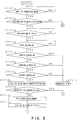
- Fig. 5 is a flowchart showing the operations of the sheet counter system shown in Fig. 1.
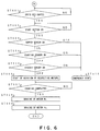
- Fig. 6 is a flowchart showing the operations of the sheet counter system shown in Fig. 1.
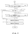
- Fig. 7 is a flowchart showing the operations of the sheet counter system shown in Fig. 1.
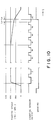
- Fig. 8 is a timing chart showing the operation of the sheet counter system shown in Fig. 1.
- Fig. 9 is a timing chart showing the operation of the sheet counter system shown in Fig. 1.
- Fig. 10 is a timing chart showing the operation of the sheet counter system shown in Fig. 1.
- Fig. 11 is a timing chart showing the operation of the sheet counter system shown in Fig. 1.
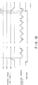
- Fig. 12 is a timing chart showing the operation of the sheet counter system shown in Fig. 1.
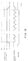
- Fig. 13 is a timing chart showing the operation of the sheet counter system shown in Fig. 1.
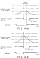
- Fig. 14A is a timing chart showing the operation of the sheet counter system shown in Fig. 1.
- Fig. 14B is a timing chart showing the operation of the sheet counter system shown in Fig. 1.
- Fig. 15A is a cross sectional view showing an example of the structural assembly of the conventional sheet counter system.
- Fig. 15B is a cross sectional view showing an example of the structural assembly of the conventional sheet counter system.
- Fig. 16 is a timing chart showing an example of the operation of the sheet counter system shown in Figs. 15A and 15B.
- Fig. 17 is a timing chart showing another example of the operation of the sheet counter system shown in Fig. 15A and 15B.
- a preferred embodiment of a sheet counter system according to this invention will now be described by taking the example of a bill counter system capable of carrying out counting processing of a bill having a length of 50-100 mm along a carrying (transfer) direction.
- Fig. 1 The structural assembly of the bill counter system according to this embodiment is shown in Fig. 1. Furthermore, a control circuit of this bill counter system is shown in a block diagram in Fig. 2.
- a kicker roller 12, feed rollers 13, and a gate roller 14 within a casing 23 constitute feeding means for feeding out bills 10 stacked within a hopper section 11. Respective components of the feeding means are driven by a DC motor M1 (see Fig. 2).
- feed rollers 13 are fixed on a feed roller shaft in the state positioned on the both sides of a feed roller 13' (which will be described later) constituting the carrying means in the same manner as in Fig. 15B, respectively.
- a roller having a diameter of 40 mm (outer circumference is about 125 mm) and provided with a friction portion 12a having an angle of about 60 degrees is used as the kicker roller 12. Furthermore, a roller having a diameter of 40 mm (outer circumference is about 125 mm) and provided with a friction portion 13a having an angle of about 75 degrees is used as the feed roller 13. This friction portion 13a is caused to be of a structure such that it rotates in a manner delayed by 4 degrees relative to the friction portion 12a of the kicker roller 12.
- the feed roller 13' at the central portion fixed on the feed roller shaft, a roller 15 opposite to the feed roller 13', and acceleration rollers 16, 17 constitute carrying means for carrying (transferring) bills 10 fed out by the feeding means.
- a roller having a diameter of 40 mm (outer circumference is about 125 mm) and provided with a friction portion 13a' having an angle of about 155 degrees is used similarly to the above-described feed roller 13.
- the feed roller 13' is caused to be of a structure such that it rotates in a manner delayed by 4 degrees relative to the friction portion 12a of the kicker roller 12. Therefore, the initial end of the friction portion 13a and the initial end of the friction portion 13a' have the same angular position.
- the acceleration rollers 16, 17 are connected to the above-described DC motor M1 by means of an one-way clutch.
- a fly-wheel 16a doubling as a slit circular plate is attached on the acceleration roller 16 so that inertia is caused to be large.
- the acceleration rollers 16, 17 are driven by inertia even after the DC motor M1 is stopped, thus making it possible to carry bills 10.
- Guide plates 19a, 19b form a carrying path for guiding bills 10 carried or transferred to a stacker fan 18 which will be described later.
- the stacker fan 18 serves to take, one by one, bills 10 carried by the carrying means into the fans, thus to stack them within the stacker 20.
- This stacker fan 18 is driven by an independent motor M2 (see Fig. 2).
- a hopper sensor S1 detects whether or not there is any bill 10 within the hopper section 11.
- the distance between the hopper sensor S1 and the gate roller 14 is set to 30 mm.
- a light receiving element S2' and a light emitting element S2'' constitute a counting sensor S2 for counting the number of bills 10 carried by the above-described carrying means.
- the carrying distance between the counting sensor S2 and the above-described gate roller 14 is set to 70 mm, and the carrying distance between the hopper sensor S1 and the counting sensor S2 is set to 100 mm.
- a stacker sensor S3 detects whether or not there is any bill 10 within the stacker 20.
- An encoder S4 detects slits formed at a fixed interval at the peripheral portion of the fly-wheel 6a doubling as a slit circular plate to thereby measure the circumferential speed thereof. Thus, the feeding speed and the carrying speed of bills 10 are calculated.
- a control unit 21 controls DC motors M1, M2 on the basis of signals inputted from an operation panel 22 and respective sensors S1, S2, S3 and S4.
- the control unit 21 repeats checking as to whether or not designation of the processing mode by the operation panel 22 is carried out (Fig. 3; ST 301).
- the control unit 21 judges the kind of the designated processing mode (ST 302).
- the control unit 21 executes the processing at step ST 303 and steps subsequent thereto.
- an ordinary counting processing mode mode for simply counting the total number of bills 10) is designated
- the control unit 21 executes the processing at step ST 601 (described later) and steps subsequent thereto (see Fig. 6).
- checking as to whether or not designation of a speed by the operation panel 22 is carried out is first repeated (ST 303). When that speed is designated, checking as to whether the start button is turned ON is then repeated (ST 304).
- the length in a carrying direction of a bill to be subjected to counting processing is measured by the bill 10 first carried (ST 310).
- This measurement can be carried out by a time period during which the counting sensor S2 is turned ON and detection of the number of slits of the fly-wheel 6a by the encoder S4 within that time period, i.e., count value of the number of pulses.
- the rotational number of the DC motor M2 (i.e., the rotational number of the stacker fan 18) is re-set to values shown in Table 1 (ST 311).
- the control unit 21 judges as to whether the speed mode is 500/minute, 1000/minute or 1500/minute (Fig. 4: ST 401). As a result, In the case where the speed mode is judged to be 500/minute, the control unit 21 executes processing at step ST 501 and steps subsequent thereto which will be described later (see Fig. 5).
- a predetermined value i.e., a predetermined number of bills ("a bill preceding by a fixed number of bills relative to an n-th bill (n is a predetermined set value" in this invention is detected) is repeated (ST402).
- the control unit 21 carries the bill 10 by a predetermined distance thereafter to sequentially carry out braking of the DC motors M1, M2 (ST405-ST409) to stop these motors (see Fig. 8).
- a predetermined distance at this time i.e., a carrying quantity of the bill 10 is given by L x -L0.
- the timing of braking of the DC motor M2 is caused to be in correspondence with a later time point between the time point when a predetermined time (e.g., 500 m sec) elapses after braking of the DC motor M1 is carried out and the time point when no pulse is outputted from the encoder S4.
- this bill 10 is carried by a predetermined distance thereafter to carry out braking of the DC motor M1, thereby preventing the DC motor M1 from being stopped before the final bill 10 is taken into the stacker fan 18.
- the control unit 21 immediately carries out braking of the DC motor M1 (ST 408), thus to stop the DC motor M1 (see Fig. 9). In accordance with the same procedure as in the above-described case, braking of the DC motor M2 is carried out (ST 409).
- the DC motor M1 is decelerated or braked so that the speed of 500/minute is provided (ST 403, see Figs. 10 and 11).
- the control unit 21 immediately carries out braking of the DC motor M1 at the time point when the front end of the hundredth bill reaches the counting sensor S2 (ST 408) to stop the DC motor M1 (see Fig. 11). In accordance with the same procedure as in the above-described case, braking of the DC motor M2 is carried out (ST 409).
- the control unit 21 immediately carries out braking of the DC motors M1, M2 (ST502-ST505) to stop these motors (see Fig. 13).
- the next (one hundred first) sheet or the like can be prevented from being fed out from the rollers 13, 14.
- control unit 21 first repeats checking as to whether or not designation of speed by the operation panel 22 is carried out (Fig. 6; ST 601). As a result, when that speed is designated, checking as to whether or not the start button is turned ON is then repeated (ST 602).
- the control unit 21 checks the hopper sensor S1 (ST 603). As a result, when the hopper sensor S1 is in an OFF state, the control unit 21 judges that there is no bill 10 within the hopper section 11 to stop the counter system, thus informing an operator of it by an alarm, etc. (ST 610).
- the control unit 21 checks the counting sensor S2 (ST 604). As a result, when the counting sensor S2 is in an ON state, the control unit 21 judges that any bill 10 exists to stop the counter system (ST 610). In contrast, when the counting sensor S2 is in an OFF state, the control unit 21 then checks the stacker sensor S3 (ST 605). As a result, when the stacker sensor S3 is in an ON state, the control unit 21 judges that any bill 10 exists to stop the counter system (ST 610). In contrast, if the stacker sensor S3 is in an OFF state, the control unit 21 judges that there is no extraordinary state, thus to start rotation of the DC motors M1, M2 (ST 606).
- control unit 21 repeats, by using the hopper sensor S1 and the counting sensor S2, checking as to whether all bills 10 are carried or transferred from the hopper section 11 to the stacker 20 (i.e., whether or not the counting processing is completed) (ST 607).
- the control unit 21 carries out braking of the DC motors M1, M2 in accordance with the same procedure as those of the ST 408, ST 409 (ST 608, 609) to stop these motors.
- control unit 21 repeats checking as to whether or not the front end of the bill 10 reaches the counting sensor S2 (Fig. 7; ST 701).
- the control unit 21 carries the bill 10 by a predetermined distance in the case where the speed mode is 500/minute thereafter to carry out braking of the DC motors M1, M2 (ST702-ST705) in accordance with the same procedure as those of ST 408, ST 409 to stop these motors (see Fig. 14A).
- the batch number is 1, it is unable to measure the length of the bill. Therefore, in this case, it is impossible to set "a predetermined distance", i.e., a carrying quantity of the bill 10 to L x -L0. Accordingly, the bill length is considered to be 90 mm to calculate L x -L0 ("the predetermined distance" is thus equal to 30 mm in the case of this embodiment).
- the bath number is 1, braking is to be ordinarily carried out immediately after or before the carrying speed reaches a designated value (value of the speed mode). Accordingly, in order to prevent the DC motor M1 from being stopped before the first bill 10 is taken into the stacker fan 18, it is desirable to set the estimated value of the bill length to a longer value.
- the control unit 21 immediately carries out braking of the DC motor M1 (ST 702, ST 704) to stop this motor (see Fig. 14B. This figure shows the example of 1500/minute).
- the control unit 21 stops the DC motor M2 in accordance with the same procedure of that at ST 409 (ST 705).
- measurement of the feeding speed is carried out by the encoder S4.
- the fly-wheel 6a doubling as slit circular plate measured by the encoder S4 can rotate by inertia through the one-way clutch. Namely, since when the DC motor M1 rotates in an acceleration state (at the time of starting) or rotates at a constant speed, rotation of the DC motor M1 is transmitted to the fly-wheel 6a. Accordingly, a measured value of the encoder S4 for measuring rotation of the fly-wheel 6a is considered to be based on a value obtained by carrying out measurement of rotation of the DC motor M1. In this embodiment, the following measure is taken with a view to reducing the cost of the system.
- this invention is not limited to the above-described embodiment.
- a configuration such that a slit circular plate is fixed on the feed roller shaft where feed rollers 13, 13, 13' are fixed to measure its rotation by using the encoder S4.
- deceleration or braking is started from the ninety sixth sheet (bill) or the like. Further, when the speed mode is 1000/minute, deceleration or braking is started from the ninety seventh sheet (bill) or the like. In other words, deceleration or braking is applied at the count time point when the minimum sheets in which deceleration and braking can be carried out in dependency upon processing speed are left(the ninety sixth or the ninety seventh sheet (bill) in the above-described embodiment. This is done in order to allow the counter system to carry out constant speed processing of sheets as many as possible to improve the processing efficiency. It is a matter of course that the number of sheets may fixed irrespective of speed.
- a fixed number of sheets of the expression of "sheet or the like preceding by a fixed number of sheets" in the invention may be different sets of fixed number of sheets in dependency upon alternation of the carrying speed mode, or may be fixed irrespective of alteration of the carrying speed mode.
- the stacking means according to the present invention is not limited to the embodiment which uses the stacker fan as described above.
Abstract
Description
- This invention relates to a sheet counter system, e.g., a sheet counter or a sheet discriminating counter, etc., viz., a system for carrying out counting processing of bills, checks or slips, etc.
- A conventional sheet counter system generally has a feeding part for feeding out, one by one, sheets or the like stacked within a hopper section; a carrying part for carrying the sheets or the like fed out by the feeding part; a counting part for counting the sheets or the like carried by the carrying part; and a stacking part for stacking the sheets of the like counted by the counting part.
- The essential part of one example of such conventional sheet counter system will now be described with reference to Figs. 15A and 15B.
- In these figures, a
kicker roller 32,feed rollers 33, 33 (see Fig. 15B) at the both ends of arotary shaft 41, and agate roller 34 constitute feeding (drawing) means for feeding out sheets or the like stacked or accumulated within ahopper section 31. Practically, twokicker rollers 32 are provided along their common axis, however, the explanation will be made with employing only one kicker roller. Respective components of this feeding means are driven by a drive motor (not shown). - Furthermore, a feed roller 33' at the central portion, a
roller 35 opposite to the feed roller 33', andacceleration rollers Such acceleration rollers guide plates 39a, 39b. In this example, theacceleration roller 36 is caused to have large inertia. Thus,acceleration rollers - A
stacker 40 including astacker fan 38 which represent practical coaxial two stacker fans constitutes stacking means. Astacker fan 38 stacks sheets or the like carried by the carrying means into astacker 40. Thisstacker fan 38 is driven by an independent motor. - A light emitting element S and a light receiving element S' detect sheets or the like and constitute counting means for counting the number of sheets or the like carried by the above-described carrying means.
- As one of processing modes carried out by sheet counter systems of this kind, counting batch processing is known. This counting batch processing is a mode adapted so that when a predetermined number (hereinafter referred to as "a batch number") of sheets or the like are stacked within the
stacker 40, the feeding means and/or the carrying means are once stopped. In accordance with this processing mode, sheets or the like within thestacker 40 are taken out every time the feeding means or the carrying means is stopped thereafter to restart such means for a second time, thereby making it possible to sort, every batch number, the sheets or the like which have been subjected to counting processing. - For example, when it is assumed that the batch number is "100", the feeding means is stopped at the time point when the hundredth sheet or the like is fed out from the
hopper section 31, so the one hundred first sheet and sheets succeeding thereto or the like are not fed out from thehopper section 31. When the hundredth sheet or the like is carried or transferred up to thestacker fan 38, the carrying means is stopped. - A deceleration (braking) method when the feeding means is caused to be stopped is shown in Fig. 16. In this figure, the ordinate is a feeding speed (number (of sheets)/minute) and the abscissa is an elapsed time t. As stated above, in the conventional sheet counter system, when the final sheet (the hundredth sheet in this example) or the like before stopping is detected by the light receiving element S' of the counting means, the drive motor of the feeding means is braked. Thereafter, the feeding speed gradually lowers and becomes equal to zero after completion of the feeding operation.
- In such conventional sheet counter system, it is required to allow the counter system to become compact.
- However, in the case where such a system is caused to become compact, the spacings between respective rollers 32-37 are shortened. Accordingly, in the case where the drive motor is braked by a timing as shown in Fig. 16, there was the possibility that when the length in a carrying direction of the sheet or the like is long, the drive motor may be stopped with the back end of the sheet or the like being put between
roller pair 33, 34 (see Figs. 15A and 15B), or remaining within thehopper section 31, so the sheet or the like fails to be stacked within thestacker 40. - On the contrary, there is employed a method as shown in Fig. 17 to conduct carrying (transfer) of a predetermined distance (40 mm in this example) after the front end of the sheet or the like is detected by the counting means S, S' thereafter to brake the drive motor, thereby making it possible to eliminate the above-mentioned drawback. Namely, in accordance with this method, even in the case where sheets or the like are long, they can be securely stacked within the
stacker 40. - However, when the brake control of the drive motor is carried out by such timing to retard or delay the timing at which the drive motor is stopped, in the case where sheets or the like are short oppositely to the above, there occurs a new drawback such that when the final (hundredth) sheet or the like before stopping reaches the
stacker fan 38, the next (one hundred first) sheet or the like may be fed out from therollers - Namely, the time period from the time when one hundredth sheet or the like is carried or transferred from the
hopper section 31 and one hundred first sheet or the like comes into contact with thekicker roller 32, thefeed rollers gate roller 34 until these rollers are stopped becomes longer according as the length of the sheet or the like becomes shorter. Such condition in which a part of the one hundred first sheet protrudes into the transferring path from thefeed roller 33 and thegate roller 34 when the hundredth sheet is transferred and the feeding of next sheet is stopped is defined as "excessive feeding". - Since such excessive feeding of the sheet or the like takes place in response to a contact as described above, according as the length of the sheet or the like becomes shorter (i.e., the contact time becomes longer), an excessive feeding quantity becomes greater.
- Accordingly, when an excessive feeding quantity of the one hundred first sheet or the like becomes greater as described above, the possibility that such sheet or the like may be damaged in taking out the sheet or the like from between
rollers hopper section 31 is one hundred ten (110), and one hundred (100) sheets or the like are stacked within thestacker 40 and the remaining ten (10) sheets or the like are taken out from the hopper section, such problem would occur. - Furthermore, in such a case that a sheet detection sensor is provided in proximity of the
kicker roller 32 at thehopper section 31 to detect whether or not there are remaining sheets or the like, inconveniences as described below also take place. - (1) There are instances where when one hundred and one sheets or the like are stacked in the
hopper 31 and one hundred first sheet is excessively fed out, if excessive feeding quantity is large, the back end of that sheet or the like is passed through the sheet detection sensor position, so it will be judged that there is no sheet or the like within thehopper section 31 although the one hundred and first sheet or the like is left therein. - (2) Even in the case where when the number of sheets or the like stacked in advance within the
hopper section 31 is one hundred ten (110), and one hundred (100) sheets or the like are fed and stacked in thestacker 40 and the remaining ten (10) sheets or the like are taken out from the hopper section, an operator forgets taking out one hundred first sheet or the like which has been excessively fed out, there are instances where it may be judged that no sheet or the like is left within thehopper section 31 in spite of the one hundred and first sheet or the like is left within thehopper section 31. - (3) In the case where there remains one of sheets or the like which have been excessively fed out in this way and counting processing is performed, remaining sheets and the like are also counting processed. As a result, the counted number of sheets or the like and the counted number of sheets or the like stacked within the
hopper section 31 are not in correspondence with each other, thus constituting the cause of trouble. - On the other hand, in a conventional sheet counter system as described above, it is also required to improve the processing speed.
- When it is now assumed that the carrying speed of the sheet or the like is caused to be high in order to improve the processing speed, in the case where the drive motor is braked after the final sheet or the like before stopping is detected by the light receiving element S' as shown in Fig. 16, the stop timing of the drive motor is delayed, so the next sheet or the like would be fed out. Accordingly, also in this case, drawbacks as in the above-mentioned items (1)-(3) take place.
- On the contrary, in order to eliminate such drawback, the inventor of this application tried a method in which when a sheet (the ninety sixth sheet in this example) or the like preceding by a fixed number of sheets relative to the final sheet before stopping is detected by the light receiving element S', the feeding speed is caused to be low, and the drive motor is braked after the final (hundredth) sheet or the like is detected by the light receiving element S'.
- With such method, however, feeding speeds at the time point when the hundredth sheet or the like is detected by the light receiving element S' would become diverse, thus failing to precisely control the stop timing. For example, when the stop timing is caused to be earlier than a set value, the carrying means is stopped before the hundredth sheet or the like reaches the
stacker fan 38, so this sheet would be left within the carrying path. - For this reason, the inventor of this application tried a method in which a feeding speed at the time point when the hundredth sheet or the like is detected by the light receiving element S' is measured, whereby when the measured speed is less than a reference speed, the sheet or the like is further carried or transferred by a predetermined distance thereafter to brake the drive motor.
- With such method, however, in the case where the length of the sheet or the like is long, satisfactory result was provided. In contrast, in the case where the length of the sheet is short, the one hundred first sheet or the like was fed out. Accordingly, also in this case, drawbacks as in the above-described items (1)-(3) may take place.
- Accordingly, an object of this invention is to provide a sheet counter system in which even in the case where counting processing of sheets or the like having a long length in a carrying direction is carried out, the counter system is capable of securely stacking processed sheets or the like, and even in the case where counting processing of sheets or the like having a short length in the carrying direction is carried out, there is no possibility that a sheet or the like subsequent to a sheet of the batch number may be fed out.
- According to one aspect of the present invention, there is provided a sheet counter system comprising:
feeding means for feeding out, one by one, sheets or the like stacked within a hopper section;
carrying means for carrying said sheets or the like fed out by said feeding means;
counting means for counting said sheets or the like carried by said carrying means;
stacking means for stacking said sheets or the like counted by said counting means; and
control means such that in the case where the length of said sheet or the like is less than a length reference value, said control means starts braking of said feeding means when the front end of an n-th sheet (n is a predetermined set value) or the like which has been fed out is detected by said counting means, while in the case where the length of said sheet or the like is greater than said length reference value, said control means starts braking of said feeding means when a carrying distance after the front end of the n-th sheet or the like which has been fed out is detected by said counting means reaches a predetermined distance to thereby stop feeding by said feeding means when the counted result of said counting means reaches a predetermined number of sheets. - In the first invention, in the case where the length of the sheet or the like is less than a length reference value, when the front end of an n-th sheet (n is a predetermined set value) or the like is detected by the counting means, braking of the feeding means is started, while in the case where the length of the sheet or the like is greater than the length reference value, when a carrying distance after the front end of the final sheet or the like before stopping is detected by the counting means reaches a predetermined distance, braking of the feeding means is started.
- According to another aspect of the present invention, there is provided a sheet counter comprising:
feeding means for feeding out, one by one, sheets or the like stacked within a hopper section;
carrying means for carrying said sheets or the like fed out by said feeding means;
counting means for counting said sheets or the like carried by said carrying means;
stacking means for stacking said sheets or the like counted by said counting means; and
control means such that when a sheet or the like preceding by a fixed number of sheets relative to an n-th sheet (n is a predetermined set value) or the like is detected by said counting means, said control means starts braking of said feeding means, in the case where the length of said sheet or the like is less than a length reference value and in the case where the length of said sheet or the like is greater than said length reference value and a feeding speed when the front end of said n-th sheet or the like which has been fed out is detected by said counting means is above a speed reference value, said control means starts braking of said feeding means when the front end of the n-th sheet or the like is detected, and in the case where the length of said sheet or the like is greater than said length reference value and a feeding speed when the front end of the n-th sheet or the like which has been fed out is detected by said counting means is smaller than said speed reference value, said control means starts braking of said feeding means when a carrying distance from the time of detection of the front end of the n-th sheet or the like reaches a predetermined distance to thereby stop feeding by said feeding means when the counted result of said counting means reaches a predetermined number of sheets. - In the second invention, in the case where the length of the sheet or the like is less than a length reference value and in the case where the length of the sheet or the like is greater than the length reference value and a feeding speed when the front end of an n-th sheet (n is a predetermined set value) or the like which has been fed out is detected by the counting means is above a speed reference value, when the front end of the n-th sheet or the like which has been fed out reaches the counting means, braking of the feeding means is started. On the other hand, in the case where the length of the sheet or the like is greater than the length reference value and a feeding speed when the front end of the n-th sheet or the like which has been fed out is smaller than the speed reference value, when a carrying distance after the front end of the n-th sheet or the like which has been fed out reaches the counting means reaches a predetermined distance, braking of the feeding means is started.
- Accordingly, it is possible to provide a sheet counter system in which even in the case where counting processing of sheets or the like having a long length in a carrying direction is carried out, processed sheets or the like can be securely stacked, and even in the case where counting processing of sheets or the like having a short length in the carrying direction is carried out, there is no possibility that a sheet succeeding to a sheet of the batch number may be fed out.
- In the accompanying drawings:
- Fig. 1 is a cross sectional view showing structural assembly of a sheet counter system according to an embodiment of this invention.
- Fig. 2 is a block diagram showing a control circuit of the sheet counter system shown in Fig. 1.
- Fig. 3 is a flowchart showing the operations of the sheet counter system shown in Fig. 1.
- Fig. 4 is a flowchart showing the operations of the sheet counter system shown in Fig. 1.
- Fig. 5 is a flowchart showing the operations of the sheet counter system shown in Fig. 1.
- Fig. 6 is a flowchart showing the operations of the sheet counter system shown in Fig. 1.
- Fig. 7 is a flowchart showing the operations of the sheet counter system shown in Fig. 1.
- Fig. 8 is a timing chart showing the operation of the sheet counter system shown in Fig. 1.
- Fig. 9 is a timing chart showing the operation of the sheet counter system shown in Fig. 1.
- Fig. 10 is a timing chart showing the operation of the sheet counter system shown in Fig. 1.
- Fig. 11 is a timing chart showing the operation of the sheet counter system shown in Fig. 1.
- Fig. 12 is a timing chart showing the operation of the sheet counter system shown in Fig. 1.
- Fig. 13 is a timing chart showing the operation of the sheet counter system shown in Fig. 1.
- Fig. 14A is a timing chart showing the operation of the sheet counter system shown in Fig. 1.
- Fig. 14B is a timing chart showing the operation of the sheet counter system shown in Fig. 1.
- Fig. 15A is a cross sectional view showing an example of the structural assembly of the conventional sheet counter system.
- Fig. 15B is a cross sectional view showing an example of the structural assembly of the conventional sheet counter system.
- Fig. 16 is a timing chart showing an example of the operation of the sheet counter system shown in Figs. 15A and 15B.
- Fig. 17 is a timing chart showing another example of the operation of the sheet counter system shown in Fig. 15A and 15B.
- A preferred embodiment of a sheet counter system according to this invention will now be described by taking the example of a bill counter system capable of carrying out counting processing of a bill having a length of 50-100 mm along a carrying (transfer) direction.
- The structural assembly of the bill counter system according to this embodiment is shown in Fig. 1. Furthermore, a control circuit of this bill counter system is shown in a block diagram in Fig. 2.
- In Fig. 1, a
kicker roller 12, feed rollers 13, and agate roller 14 within acasing 23 constitute feeding means for feeding outbills 10 stacked within a hopper section 11. Respective components of the feeding means are driven by a DC motor M₁ (see Fig. 2). In this embodiment, feed rollers 13 are fixed on a feed roller shaft in the state positioned on the both sides of a feed roller 13' (which will be described later) constituting the carrying means in the same manner as in Fig. 15B, respectively. - In this embodiment, a roller having a diameter of 40 mm (outer circumference is about 125 mm) and provided with a friction portion 12a having an angle of about 60 degrees is used as the
kicker roller 12. Furthermore, a roller having a diameter of 40 mm (outer circumference is about 125 mm) and provided with a friction portion 13a having an angle of about 75 degrees is used as the feed roller 13. This friction portion 13a is caused to be of a structure such that it rotates in a manner delayed by 4 degrees relative to the friction portion 12a of thekicker roller 12. - The feed roller 13' at the central portion fixed on the feed roller shaft, a
roller 15 opposite to the feed roller 13', andacceleration rollers bills 10 fed out by the feeding means. As the feed roller 13', a roller having a diameter of 40 mm (outer circumference is about 125 mm) and provided with a friction portion 13a' having an angle of about 155 degrees is used similarly to the above-described feed roller 13. The feed roller 13' is caused to be of a structure such that it rotates in a manner delayed by 4 degrees relative to the friction portion 12a of thekicker roller 12. Therefore, the initial end of the friction portion 13a and the initial end of the friction portion 13a' have the same angular position. Theacceleration rollers acceleration roller 16 so that inertia is caused to be large. Thus, theacceleration rollers bills 10. -
Guide plates 19a, 19b form a carrying path for guidingbills 10 carried or transferred to astacker fan 18 which will be described later. - The
stacker fan 18 serves to take, one by one, bills 10 carried by the carrying means into the fans, thus to stack them within thestacker 20. Thisstacker fan 18 is driven by an independent motor M₂ (see Fig. 2). - Assuming now that the circumferential speed of the
kicker roller 12 is V₁, respective components are rotationally driven so that the circumferential speed of the feed roller is V₁, the circumferential speeds of theacceleration rollers stacker fan 18 is V₁/3. - A hopper sensor S₁ detects whether or not there is any
bill 10 within the hopper section 11. In this embodiment, the distance between the hopper sensor S₁ and thegate roller 14 is set to 30 mm. - A light receiving element S₂' and a light emitting element S₂'' constitute a counting sensor S₂ for counting the number of
bills 10 carried by the above-described carrying means. In this embodiment, the carrying distance between the counting sensor S₂ and the above-describedgate roller 14 is set to 70 mm, and the carrying distance between the hopper sensor S₁ and the counting sensor S₂ is set to 100 mm. - A stacker sensor S₃ detects whether or not there is any
bill 10 within thestacker 20. - An encoder S₄ detects slits formed at a fixed interval at the peripheral portion of the fly-wheel 6a doubling as a slit circular plate to thereby measure the circumferential speed thereof. Thus, the feeding speed and the carrying speed of
bills 10 are calculated. - A control unit 21 controls DC motors M₁, M₂ on the basis of signals inputted from an
operation panel 22 and respective sensors S₁, S₂, S₃ and S₄. - It is to be noted that while a DC motor is used as each drive motor as described above in this embodiment, an AC motor, etc. may be used as a matter of course. In addition, a short brake is employed as braking of the DC motors M₁, M₂.
- The operation of the bill counter system according to this embodiment will now be described with reference to the flowcharts of FIGS. 3-7 and the timing charts of FIGS. 8-14.
- When a main power supply of the bill counter system is turned ON, the control unit 21 repeats checking as to whether or not designation of the processing mode by the
operation panel 22 is carried out (Fig. 3; ST 301). When an operator designates a processing mode, the control unit 21 then judges the kind of the designated processing mode (ST 302). As a result, when it is judged that the batch processing is designated, the control unit 21 executes the processing at step ST 303 and steps subsequent thereto. On the other hand, when it is judged that an ordinary counting processing mode (mode for simply counting the total number of bills 10) is designated, the control unit 21 executes the processing at step ST 601 (described later) and steps subsequent thereto (see Fig. 6). - In the batch processing, checking as to whether or not designation of a speed by the
operation panel 22 is carried out is first repeated (ST 303). When that speed is designated, checking as to whether the start button is turned ON is then repeated (ST 304). - When the start button is turned ON, whether or not bills 10 are stacked within the hopper section 11 is first checked by the hopper sensor S₁. As a result, if the hopper sensor S₁ is in an OFF state, it is judged that there is no
bill 10 in the hopper 11 to stop the bill counter system to inform an operator of it by an alarm, etc. - On the other hand, in the case where the hopper sensor S₁ is in an ON state, whether or not bills are clogged within the counter system is then checked by using the counting sensor S₂ (ST 306). As a result, if the counting sensor S₂ is in an ON state, it is judged that there exists any
bill 10, thus stopping the counter system (ST 312). In contrast, if the counting sensor S₂ is in an OFF state, whether or not anybill 10 remains within thestacker 20 is then checked by the stacker sensor S₃ (ST 307). As a result, if the stacker sensor S₃ is in an ON state, it is judged that there exists anybill 10, thus stopping the counter system (ST 312). On the other hand, if the stacker sensor S₃ is in an OFF state, it is judged that there is no extraordinary state, thus starting rotation of the DC motors M₁, M₂ (ST 308). - Subsequently, whether the batch number inputted by the
operation panel 22 is 1 or a value more than 1, i.e., 2 or more is checked (ST 309). As a result, if the batch number is 1, the control unit 21 executes processing at step ST 701 and steps subsequent thereto which will be described later (see Fig. 7). - On the other hand, in the case where the batch number is a value more than 1, i.e. 2 or more, the length in a carrying direction of a bill to be subjected to counting processing is measured by the
bill 10 first carried (ST 310). This measurement can be carried out by a time period during which the counting sensor S₂ is turned ON and detection of the number of slits of the fly-wheel 6a by the encoder S₄ within that time period, i.e., count value of the number of pulses. - According to the measured result of the bill length and the speed mode (i.e., circumferential speed of the DC motor M₁), the rotational number of the DC motor M₂ (i.e., the rotational number of the stacker fan 18) is re-set to values shown in Table 1 (ST 311).
Table 1 ROTATION NO. OF M₂ SPEED MODE 500/MIN. 1000/MIN. 1500/MIN. BILL LENGTH 91 mm or more 130 rpm 240 rpm 240 rpm Less than 91 mm 80 rpm 130 rpm 130 rpm - Subsequently, the control unit 21 judges as to whether the speed mode is 500/minute, 1000/minute or 1500/minute (Fig. 4: ST 401). As a result, In the case where the speed mode is judged to be 500/minute, the control unit 21 executes processing at step ST 501 and steps subsequent thereto which will be described later (see Fig. 5).
- On the other hand, in the case where the speed mode is 1000/minute or 1500/minute, checking as to whether or not a count value by the counting sensor S₂ reaches a predetermined value, i.e., a predetermined number of bills ("a bill preceding by a fixed number of bills relative to an n-th bill (n is a predetermined set value" in this invention is detected) is repeated (ST402).
- Assuming now that the batch number is 100, in the case where the speed mode is 1500/minute, when the front end of the ninety
sixth bill 10 reaches the position on the counting sensor S₂, it is judged that the count value reaches the corresponding number, thus decelerating or braking the DC motor M₁ so that the speed of 500/minute is provided (ST 403, see Figs. 8 and 9). Then, judgment as to whether or not the count value of the counting sensor S₂ reaches the batch number (100 in this embodiment) is repeated (ST 404). - When the front end of the
bill 10 of the batch number reaches the position on the counting sensor S₂, if a measured value Lx of the bill length is greater than a length reference value L₀ (which is assumed to be "60 mm" in this case) and the speed of the DC motor M₁ (measured value by the encoder S₄) is smaller than a speed reference value (which is assumed to be "1000/minute" in this case), the control unit 21 carries thebill 10 by a predetermined distance thereafter to sequentially carry out braking of the DC motors M₁, M₂ (ST405-ST409) to stop these motors (see Fig. 8). In this embodiment, "a predetermined distance" at this time, i.e., a carrying quantity of thebill 10 is given by Lx-L₀. In addition, the timing of braking of the DC motor M₂ is caused to be in correspondence with a later time point between the time point when a predetermined time (e.g., 500 m sec) elapses after braking of the DC motor M₁ is carried out and the time point when no pulse is outputted from the encoder S₄. - When the bill length Lx is greater than the length reference value L₀ and the speed of the DC motor M₁ is smaller than the speed reference value, this
bill 10 is carried by a predetermined distance thereafter to carry out braking of the DC motor M₁, thereby preventing the DC motor M₁ from being stopped before thefinal bill 10 is taken into thestacker fan 18. - On the other hand, when the bill length Lx is greater than the length reference value L₀ ("60 mm") and the speed of the DC motor M₁ (measured value by the encoder S₄) is more than 1000/minute, and when the bill length Lx is less than 60 mm (ST 405, 406), the control unit 21 immediately carries out braking of the DC motor M₁ (ST 408), thus to stop the DC motor M₁ (see Fig. 9). In accordance with the same procedure as in the above-described case, braking of the DC motor M₂ is carried out (ST 409).
- As stated above, when the bill length Lx is greater than the length reference value L₀ and the speed of the DC motor M₁ is above the speed reference value, or when the bill length Lx is equal to the length reference value L₀ or is smaller than that, braking of the DC motor M₁ is immediately carried out, thereby making it possible to prevent the next (one hundred first) sheet or the like from being fed out from the
rollers 13, 14. - In the case where the speed mode setting is 1000/minute, when the front end of the ninety
seventh bill 10 reaches the position on the counting sensor S₂, the DC motor M₁ is decelerated or braked so that the speed of 500/minute is provided (ST 403, see Figs. 10 and 11). - Judgment as to whether or not the count value of the counting sensor S₂ reaches 100 (batch number) is repeated (ST 404). As a result, when it is judged that the front end of the
hundredth bill 10 reaches the position on the counting sensor S₂, if the bill length Lx is greater than the length reference value L₀ (60 mm) and the speed of the DC motor M₁ (measured value by the encoder S₄) is smaller than the speed reference value (which is assumed to be "1000/minutes" in this case), the control unit 21 carries thebill 10 by a predetermined distance (Lx-L₀) thereafter to sequentially carry out braking of respective DC motors M₁, M₂ (ST 405-ST409), thus to stop these motors (see Fig. 10). It is to be noted that since deceleration or braking is carried out from the speed of 1000/minute, the speed is necessarily smaller than the speed reference value (1000/minute). In the case where Lx is greater than L₀, such an operation is necessarily carried out. - On the other hand, when the bill length Lx is less than the length reference value, i.e., 60 mm (ST 405 and 406), the control unit 21 immediately carries out braking of the DC motor M₁ at the time point when the front end of the hundredth bill reaches the counting sensor S₂ (ST 408) to stop the DC motor M₁ (see Fig. 11). In accordance with the same procedure as in the above-described case, braking of the DC motor M₂ is carried out (ST 409).
- Furthermore, when the speed mode setting is 500/minute, judgment as to whether or not the count value of the counting sensor S₂ reaches 100 (batch number) is repeated (Fig. 5; ST 501). When the front end of the
hundredth bill 10 reaches the position on the counting sensor S₂, if the bill length Lx is greater than the length reference value L₀ (60 mm), the control unit 21 carries thisbill 10 by a predetermined distance (Lx-L₀) thereafter to carry out braking of the DC motors M₁, M₂ (ST502-ST505) in accordance with the same procedure as in the steps ST 408, ST 409 to stop these motors (see Fig. 12). Thus, the DC motors M₁, M₂ are prevented from being stopped before thefinal bill 10 is taken into thestacker fan 18. - On the other hand, when the bill length Lx is less than 60 mm, the control unit 21 immediately carries out braking of the DC motors M₁, M₂ (ST502-ST505) to stop these motors (see Fig. 13). Thus, the next (one hundred first) sheet or the like can be prevented from being fed out from the
rollers 13, 14. - Explanation will now be given in connection with the case where an ordinary counting processing mode is designated as the result of judgment at ST 302 (see Fig. 3).
- In this case, the control unit 21 first repeats checking as to whether or not designation of speed by the
operation panel 22 is carried out (Fig. 6; ST 601). As a result, when that speed is designated, checking as to whether or not the start button is turned ON is then repeated (ST 602). - When the start button is turned ON, the control unit 21 checks the hopper sensor S₁ (ST 603). As a result, when the hopper sensor S₁ is in an OFF state, the control unit 21 judges that there is no
bill 10 within the hopper section 11 to stop the counter system, thus informing an operator of it by an alarm, etc. (ST 610). - On the other hand, in the case where the hopper sensor S₁ is turned ON, the control unit 21 then checks the counting sensor S₂ (ST 604). As a result, when the counting sensor S₂ is in an ON state, the control unit 21 judges that any
bill 10 exists to stop the counter system (ST 610). In contrast, when the counting sensor S₂ is in an OFF state, the control unit 21 then checks the stacker sensor S₃ (ST 605). As a result, when the stacker sensor S₃ is in an ON state, the control unit 21 judges that anybill 10 exists to stop the counter system (ST 610). In contrast, if the stacker sensor S₃ is in an OFF state, the control unit 21 judges that there is no extraordinary state, thus to start rotation of the DC motors M₁, M₂ (ST 606). - Then, the control unit 21 repeats, by using the hopper sensor S₁ and the counting sensor S₂, checking as to whether all
bills 10 are carried or transferred from the hopper section 11 to the stacker 20 (i.e., whether or not the counting processing is completed) (ST 607). As a result, when the count processing is completed, the control unit 21 carries out braking of the DC motors M₁, M₂ in accordance with the same procedure as those of the ST 408, ST 409 (ST 608, 609) to stop these motors. - Explanation will now be given in connection with the case where the designated batch number is 1 (one) as the result of judgment at ST 309 (see Fig. 3).
- In this case, in the beginning, the control unit 21 repeats checking as to whether or not the front end of the
bill 10 reaches the counting sensor S₂ (Fig. 7; ST 701). - When the front end of the
bill 10 reaches the counting sensor S₂, the control unit 21 carries thebill 10 by a predetermined distance in the case where the speed mode is 500/minute thereafter to carry out braking of the DC motors M₁, M₂ (ST702-ST705) in accordance with the same procedure as those of ST 408, ST 409 to stop these motors (see Fig. 14A). - When the batch number is 1, it is unable to measure the length of the bill. Therefore, in this case, it is impossible to set "a predetermined distance", i.e., a carrying quantity of the
bill 10 to Lx-L₀. Accordingly, the bill length is considered to be 90 mm to calculate Lx-L₀ ("the predetermined distance" is thus equal to 30 mm in the case of this embodiment). When the bath number is 1, braking is to be ordinarily carried out immediately after or before the carrying speed reaches a designated value (value of the speed mode). Accordingly, in order to prevent the DC motor M₁ from being stopped before thefirst bill 10 is taken into thestacker fan 18, it is desirable to set the estimated value of the bill length to a longer value. - On the other hand, in the case where the speed mode is 1000/minute or 1500/minute, the control unit 21 immediately carries out braking of the DC motor M₁ (ST 702, ST 704) to stop this motor (see Fig. 14B. This figure shows the example of 1500/minute). The control unit 21 stops the DC motor M₂ in accordance with the same procedure of that at ST 409 (ST 705).
- As explained above, in the bill counter system according to this embodiment, in the case where the bill length is long and a feeding speed when the front end of a bill of the batch number is detected by the counting means is low, this
bill 10 is caused to be carried or transferred by a predetermined distance and braking is then carried out. Accordingly, it hardly occurs that the DC motor M₁ is stopped with the back end of thebill 10 being put betweenroller pair 13, 14, or remaining within the hopper section 11, so thebill 10 fails to be stacked within thestacker 20. - In addition, in the case where the bill length is long and a feeding speed at the time point when the front end of a bill of the batch number is detected by the counting means is high, or in the case where the bill length is short, braking of the DC motor M₁ is carried out immediately when the bill of the batch number is detected by the counting means. Accordingly, there is no possibility that the next (one hundred first) bill may be fed out from the
rollers 13, 14. - In this embodiment, measurement of the feeding speed is carried out by the encoder S₄. The fly-wheel 6a doubling as slit circular plate measured by the encoder S₄ can rotate by inertia through the one-way clutch. Namely, since when the DC motor M₁ rotates in an acceleration state (at the time of starting) or rotates at a constant speed, rotation of the DC motor M₁ is transmitted to the fly-wheel 6a. Accordingly, a measured value of the encoder S₄ for measuring rotation of the fly-wheel 6a is considered to be based on a value obtained by carrying out measurement of rotation of the DC motor M₁. In this embodiment, the following measure is taken with a view to reducing the cost of the system. Namely, since measurement of the carrying speed of the bill and measurement of the feeding speed of the bill are carried out commonly by using the encoder S₄. The reason is that the bill feeding speed and the rotational speed of the DC motor M₁ are in proportion to each other, measure of the bill feeding speed is also measurement of the rotational speed of the DC motor M₁.
- However, this invention is not limited to the above-described embodiment. In the case where measurement of an accurate feeding speed is desired, there may be employed a configuration such that a slit circular plate is fixed on the feed roller shaft where feed rollers 13, 13, 13' are fixed to measure its rotation by using the encoder S₄.
- When the speed mode is 1500/minute, deceleration or braking is started from the ninety sixth sheet (bill) or the like. Further, when the speed mode is 1000/minute, deceleration or braking is started from the ninety seventh sheet (bill) or the like. In other words, deceleration or braking is applied at the count time point when the minimum sheets in which deceleration and braking can be carried out in dependency upon processing speed are left(the ninety sixth or the ninety seventh sheet (bill) in the above-described embodiment. This is done in order to allow the counter system to carry out constant speed processing of sheets as many as possible to improve the processing efficiency. It is a matter of course that the number of sheets may fixed irrespective of speed.
- It is therefore a matter of course that a fixed number of sheets of the expression of "sheet or the like preceding by a fixed number of sheets" in the invention may be different sets of fixed number of sheets in dependency upon alternation of the carrying speed mode, or may be fixed irrespective of alteration of the carrying speed mode.
- It is to be noted that the stacking means according to the present invention is not limited to the embodiment which uses the stacker fan as described above. For example, a stacker having toothed rollers at an entrance thereof as shown in the United States Patent No. 3,909,982, the toothed rollers being disposed between the back end of the stacked sheets or the like and the front end of the sheets or the like to be fed to locate the front end of the sheets or the like to the upper part of the stacked sheets or the like, or a stacker using endless belts instead of the above-mentioned toothed rollers for performing the same function as above, which is shown in the United States Patent No. 4,285,511, can be employed.
Claims (5)
- A sheet counter system comprising:
feeding means (12, 13, 14) for feeding out, one by one, sheets or the like (10) stacked within a hopper section (11);
carrying means (13', 15, 16, 17) for carrying said sheets or the like fed out by said feeding means;
counting means (S2) for counting said sheets or the like carried by said carrying means; and
stacking means (20) for stacking said sheets or the like counted by said counting means;
characterized in that said sheet counter system further comprises control means (21) such that in the case where the length of said sheet or the like is less than a length reference value, said control means starts braking of said feeding means when the front end of an n-th sheet (n is a predetermined set value) or the like which has been fed out is detected by said counting means, while in the case where the length of said sheet or the like is greater than said length reference value, said control means starts braking of said feeding means when a carrying distance after the front end of the n-th sheet or the like which has been fed out is detected by said counting means reaches a predetermined distance to thereby stop feeding by said feeding means when the counted result of said counting means reaches a predetermined number of sheets. - A sheet counter system as set forth in claim 1, wherein said predetermined distance is a distance given by a difference between the length of said sheet or the like and said length reference value.
- A sheet counter system comprising:
feeding means (12, 13, 14) for feeding out, one by one, sheets or the like (10) stacked within a hopper section (11);
carrying means (13', 15, 16, 17) for carrying said sheets or the like fed out by said feeding means;
counting means (S2) for counting said sheets or the like carried by said carrying means; and
stacking means (20) for stacking said sheets or the like counted by said counting means;
characterized in that said sheet counter system further comprises control means (21) such that when a sheet or the like preceding by a fixed number m (m is a predetermined set value) of sheets relative to an n-th sheet (n is a predetermined set value) or the like is detected by said counting means, said control means starts braking of said feeding means, in the case where the length of said sheet or the like is less than a length reference value and in the case where the length of said sheet or the like is greater than said length reference value and a feeding speed when the front end of said n-th sheet or the like which has been fed out is detected by said counting means is above a speed reference value, said control means starts braking of said feeding means when the front end of the n-th sheet or the like is detected, and in the case where the length of said sheet or the like is greater than said length reference value and a feeding speed when the front end of the n-th sheet or the like which has been fed out is detected by said counting means is smaller than said speed reference value, said control means starts braking of said feeding means when a carrying distance from the time of detection of the front end of the n-th sheet or the like reaches a predetermined distance to thereby stop feeding by said feeding means when the counted result of said counting means reaches a predetermined number of sheets. - A sheet counter system as set forth in claim 3, wherein said predetermined distance is a distance given by a difference between the length of said sheet or the like and said length reference value.
- A sheet counter system as set forth in claim 3, wherein said feeding speed is given by selection of speed mode.
Applications Claiming Priority (2)
| Application Number | Priority Date | Filing Date | Title |
|---|---|---|---|
| JP02038893A JP3256014B2 (en) | 1993-02-08 | 1993-02-08 | Sheet counting machine |
| JP20388/93 | 1993-02-08 |
Publications (3)
| Publication Number | Publication Date |
|---|---|
| EP0611034A2 true EP0611034A2 (en) | 1994-08-17 |
| EP0611034A3 EP0611034A3 (en) | 1994-08-31 |
| EP0611034B1 EP0611034B1 (en) | 1999-06-02 |
Family
ID=12025644
Family Applications (1)
| Application Number | Title | Priority Date | Filing Date |
|---|---|---|---|
| EP94300196A Expired - Lifetime EP0611034B1 (en) | 1993-02-08 | 1994-01-12 | Sheet counter system |
Country Status (8)
| Country | Link |
|---|---|
| US (1) | US5541393A (en) |
| EP (1) | EP0611034B1 (en) |
| JP (1) | JP3256014B2 (en) |
| KR (1) | KR100275806B1 (en) |
| CA (1) | CA2113227C (en) |
| DE (1) | DE69418741T2 (en) |
| ES (1) | ES2133481T3 (en) |
| TW (1) | TW266283B (en) |
Cited By (1)
| Publication number | Priority date | Publication date | Assignee | Title |
|---|---|---|---|---|
| CN103426022A (en) * | 2012-05-25 | 2013-12-04 | 光荣株式会社 | Paper counting machine and paper counting method |
Families Citing this family (9)
| Publication number | Priority date | Publication date | Assignee | Title |
|---|---|---|---|---|
| JP2859872B1 (en) * | 1997-06-02 | 1999-02-24 | 有限会社スガイ総業 | Paper sheet counting device |
| JPH11177758A (en) * | 1997-12-12 | 1999-07-02 | Oki Data Corp | Facsimile equipment |
| JP4791631B2 (en) * | 2000-12-26 | 2011-10-12 | 株式会社東芝 | Paper sheet processing equipment |
| JP2003216999A (en) * | 2002-01-22 | 2003-07-31 | Toshiba Corp | Handling device for paper sheets |
| JP2004043178A (en) * | 2002-05-23 | 2004-02-12 | Ricoh Co Ltd | Automatic document carrying device and image processing device |
| US6827069B1 (en) * | 2003-09-17 | 2004-12-07 | General Motors Corporation | Detection of fuel dynamical steady state |
| JP5116133B2 (en) * | 2006-08-22 | 2013-01-09 | 株式会社ユニバーサルエンターテインメント | Banknote handling equipment |
| KR101801771B1 (en) | 2015-08-17 | 2017-12-29 | 기산전자(주) | Apparatus for controlling feed rate of banknote and method thereof |
| CN112659763B (en) * | 2020-12-17 | 2022-07-19 | 云侠科技(苏州)有限公司 | Printer for office |
Citations (3)
| Publication number | Priority date | Publication date | Assignee | Title |
|---|---|---|---|---|
| USRE29470E (en) * | 1972-07-21 | 1977-11-08 | Brandt-Pra, Inc. | Control mechanisms for document-handling apparatus |
| WO1992000235A1 (en) * | 1990-06-28 | 1992-01-09 | Brandt, Inc. | Apparatus for feeding and accelerating sheets |
| GB2256483A (en) * | 1991-06-04 | 1992-12-09 | Langston Corp | Counting printed or perforated box blanks |
-
1993
- 1993-02-08 JP JP02038893A patent/JP3256014B2/en not_active Expired - Fee Related
-
1994
- 1994-01-11 CA CA002113227A patent/CA2113227C/en not_active Expired - Fee Related
- 1994-01-11 US US08/179,719 patent/US5541393A/en not_active Expired - Lifetime
- 1994-01-12 EP EP94300196A patent/EP0611034B1/en not_active Expired - Lifetime
- 1994-01-12 ES ES94300196T patent/ES2133481T3/en not_active Expired - Lifetime
- 1994-01-12 DE DE69418741T patent/DE69418741T2/en not_active Expired - Lifetime
- 1994-01-13 TW TW083100236A patent/TW266283B/zh not_active IP Right Cessation
- 1994-01-21 KR KR1019940001260A patent/KR100275806B1/en not_active IP Right Cessation
Patent Citations (3)
| Publication number | Priority date | Publication date | Assignee | Title |
|---|---|---|---|---|
| USRE29470E (en) * | 1972-07-21 | 1977-11-08 | Brandt-Pra, Inc. | Control mechanisms for document-handling apparatus |
| WO1992000235A1 (en) * | 1990-06-28 | 1992-01-09 | Brandt, Inc. | Apparatus for feeding and accelerating sheets |
| GB2256483A (en) * | 1991-06-04 | 1992-12-09 | Langston Corp | Counting printed or perforated box blanks |
Non-Patent Citations (1)
| Title |
|---|
| IBM TECHNICAL DISCLOSURE BULLETIN., vol.27, no.12, May 1985, NEW YORK US pages 6830 - 6831 'SYNCHRONOUS OPERATION CONTROL SYSTEM FOR BILL FEED DEVICE' * |
Cited By (2)
| Publication number | Priority date | Publication date | Assignee | Title |
|---|---|---|---|---|
| CN103426022A (en) * | 2012-05-25 | 2013-12-04 | 光荣株式会社 | Paper counting machine and paper counting method |
| CN103426022B (en) * | 2012-05-25 | 2017-07-07 | 光荣株式会社 | The method of counting of paper counting machine and paper |
Also Published As
| Publication number | Publication date |
|---|---|
| KR940020264A (en) | 1994-09-15 |
| DE69418741T2 (en) | 1999-10-07 |
| JPH06236463A (en) | 1994-08-23 |
| CA2113227C (en) | 1998-04-28 |
| TW266283B (en) | 1995-12-21 |
| CA2113227A1 (en) | 1994-08-09 |
| JP3256014B2 (en) | 2002-02-12 |
| EP0611034A3 (en) | 1994-08-31 |
| EP0611034B1 (en) | 1999-06-02 |
| DE69418741D1 (en) | 1999-07-08 |
| ES2133481T3 (en) | 1999-09-16 |
| KR100275806B1 (en) | 2000-12-15 |
| US5541393A (en) | 1996-07-30 |
Similar Documents
| Publication | Publication Date | Title |
|---|---|---|
| EP0611034A2 (en) | Sheet counter system | |
| US7537212B2 (en) | Sheet take-out method with cap counter with gap counter | |
| EP0263712A2 (en) | Improved motor control for banknote handling apparatus | |
| US4968015A (en) | Sheet feeding apparatus and method | |
| JPH0646926Y2 (en) | Misalignment display device for collator | |
| JPH02503668A (en) | Multiple document detector and separator | |
| JP3253721B2 (en) | Sheet counting machine | |
| JPH0116204Y2 (en) | ||
| JPH0611980Y2 (en) | Automatic paper feeder | |
| JPH0313146B2 (en) | ||
| JPS6018331Y2 (en) | Coin fall prevention device for coin wrapping machine | |
| JPH0452647Y2 (en) | ||
| JP4176551B2 (en) | Paper sheet take-out device | |
| JPS58222800A (en) | Pulse motor step-out detecting and demodulating device for paper tape reader | |
| JPH06271145A (en) | Image forming device | |
| EP0860389A2 (en) | Device and method for sensing paper entry | |
| JP2564976B2 (en) | Paper separator | |
| JPS63267658A (en) | Paper sheet accumulating mechanism | |
| JPH0319011Y2 (en) | ||
| JP2609172B2 (en) | Abnormal detection device for rotary press | |
| JPS606840Y2 (en) | Sheet detection device | |
| JPH089454B2 (en) | Paper sheet separating and feeding device | |
| JPS63245787A (en) | Counter for paper or the like | |
| JP2778385B2 (en) | Paper sheet separation and supply control device | |
| US6530525B1 (en) | Sheet counting apparatus and method |
Legal Events
| Date | Code | Title | Description |
|---|---|---|---|
| PUAI | Public reference made under article 153(3) epc to a published international application that has entered the european phase |
Free format text: ORIGINAL CODE: 0009012 |
|
| PUAL | Search report despatched |
Free format text: ORIGINAL CODE: 0009013 |
|
| AK | Designated contracting states |
Kind code of ref document: A2 Designated state(s): DE ES FR GB IT SE |
|
| AK | Designated contracting states |
Kind code of ref document: A3 Designated state(s): DE ES FR GB IT SE |
|
| 17P | Request for examination filed |
Effective date: 19941017 |
|
| GRAG | Despatch of communication of intention to grant |
Free format text: ORIGINAL CODE: EPIDOS AGRA |
|
| 17Q | First examination report despatched |
Effective date: 19980707 |
|
| GRAG | Despatch of communication of intention to grant |
Free format text: ORIGINAL CODE: EPIDOS AGRA |
|
| GRAH | Despatch of communication of intention to grant a patent |
Free format text: ORIGINAL CODE: EPIDOS IGRA |
|
| GRAH | Despatch of communication of intention to grant a patent |
Free format text: ORIGINAL CODE: EPIDOS IGRA |
|
| GRAA | (expected) grant |
Free format text: ORIGINAL CODE: 0009210 |
|
| AK | Designated contracting states |
Kind code of ref document: B1 Designated state(s): DE ES FR GB IT SE |
|
| REF | Corresponds to: |
Ref document number: 69418741 Country of ref document: DE Date of ref document: 19990708 |
|
| ET | Fr: translation filed | ||
| ITF | It: translation for a ep patent filed |
Owner name: SOCIETA' ITALIANA BREVETTI S.P.A. |
|
| REG | Reference to a national code |
Ref country code: ES Ref legal event code: FG2A Ref document number: 2133481 Country of ref document: ES Kind code of ref document: T3 |
|
| PLBE | No opposition filed within time limit |
Free format text: ORIGINAL CODE: 0009261 |
|
| STAA | Information on the status of an ep patent application or granted ep patent |
Free format text: STATUS: NO OPPOSITION FILED WITHIN TIME LIMIT |
|
| 26N | No opposition filed | ||
| REG | Reference to a national code |
Ref country code: GB Ref legal event code: IF02 |
|
| PG25 | Lapsed in a contracting state [announced via postgrant information from national office to epo] |
Ref country code: IT Free format text: LAPSE BECAUSE OF NON-PAYMENT OF DUE FEES;WARNING: LAPSES OF ITALIAN PATENTS WITH EFFECTIVE DATE BEFORE 2007 MAY HAVE OCCURRED AT ANY TIME BEFORE 2007. THE CORRECT EFFECTIVE DATE MAY BE DIFFERENT FROM THE ONE RECORDED. Effective date: 20050112 |
|
| PGFP | Annual fee paid to national office [announced via postgrant information from national office to epo] |
Ref country code: SE Payment date: 20091217 Year of fee payment: 17 |
|
| PGFP | Annual fee paid to national office [announced via postgrant information from national office to epo] |
Ref country code: IT Payment date: 20091211 Year of fee payment: 17 Ref country code: GB Payment date: 20091222 Year of fee payment: 17 Ref country code: FR Payment date: 20091221 Year of fee payment: 17 Ref country code: ES Payment date: 20100119 Year of fee payment: 17 |
|
| PGRI | Patent reinstated in contracting state [announced from national office to epo] |
Ref country code: IT Effective date: 20091201 |
|
| REG | Reference to a national code |
Ref country code: SE Ref legal event code: EUG |
|
| GBPC | Gb: european patent ceased through non-payment of renewal fee |
Effective date: 20110112 |
|
| REG | Reference to a national code |
Ref country code: FR Ref legal event code: ST Effective date: 20110930 |
|
| PG25 | Lapsed in a contracting state [announced via postgrant information from national office to epo] |
Ref country code: FR Free format text: LAPSE BECAUSE OF NON-PAYMENT OF DUE FEES Effective date: 20110131 |
|
| PG25 | Lapsed in a contracting state [announced via postgrant information from national office to epo] |
Ref country code: GB Free format text: LAPSE BECAUSE OF NON-PAYMENT OF DUE FEES Effective date: 20110112 |
|
| PG25 | Lapsed in a contracting state [announced via postgrant information from national office to epo] |
Ref country code: IT Free format text: LAPSE BECAUSE OF NON-PAYMENT OF DUE FEES Effective date: 20110112 |
|
| REG | Reference to a national code |
Ref country code: ES Ref legal event code: FD2A Effective date: 20120220 |
|
| PG25 | Lapsed in a contracting state [announced via postgrant information from national office to epo] |
Ref country code: ES Free format text: LAPSE BECAUSE OF NON-PAYMENT OF DUE FEES Effective date: 20110113 |
|
| PGFP | Annual fee paid to national office [announced via postgrant information from national office to epo] |
Ref country code: DE Payment date: 20120104 Year of fee payment: 19 |
|
| PG25 | Lapsed in a contracting state [announced via postgrant information from national office to epo] |
Ref country code: SE Free format text: LAPSE BECAUSE OF NON-PAYMENT OF DUE FEES Effective date: 20110113 |
|
| PG25 | Lapsed in a contracting state [announced via postgrant information from national office to epo] |
Ref country code: DE Free format text: LAPSE BECAUSE OF NON-PAYMENT OF DUE FEES Effective date: 20130801 |
|
| REG | Reference to a national code |
Ref country code: DE Ref legal event code: R119 Ref document number: 69418741 Country of ref document: DE Effective date: 20130801 |