EP0613060A2 - Developing cartridge having support member for rotatably supporting developing device, and developing apparatus - Google Patents
Developing cartridge having support member for rotatably supporting developing device, and developing apparatus Download PDFInfo
- Publication number
- EP0613060A2 EP0613060A2 EP94301272A EP94301272A EP0613060A2 EP 0613060 A2 EP0613060 A2 EP 0613060A2 EP 94301272 A EP94301272 A EP 94301272A EP 94301272 A EP94301272 A EP 94301272A EP 0613060 A2 EP0613060 A2 EP 0613060A2
- Authority
- EP
- European Patent Office
- Prior art keywords
- developing
- cartridge
- developing device
- developing cartridge
- support member
- Prior art date
- Legal status (The legal status is an assumption and is not a legal conclusion. Google has not performed a legal analysis and makes no representation as to the accuracy of the status listed.)
- Granted
Links
Images


Classifications
-
- G—PHYSICS
- G03—PHOTOGRAPHY; CINEMATOGRAPHY; ANALOGOUS TECHNIQUES USING WAVES OTHER THAN OPTICAL WAVES; ELECTROGRAPHY; HOLOGRAPHY
- G03G—ELECTROGRAPHY; ELECTROPHOTOGRAPHY; MAGNETOGRAPHY
- G03G15/00—Apparatus for electrographic processes using a charge pattern
- G03G15/06—Apparatus for electrographic processes using a charge pattern for developing
- G03G15/08—Apparatus for electrographic processes using a charge pattern for developing using a solid developer, e.g. powder developer
- G03G15/0896—Arrangements or disposition of the complete developer unit or parts thereof not provided for by groups G03G15/08 - G03G15/0894
-
- G—PHYSICS
- G03—PHOTOGRAPHY; CINEMATOGRAPHY; ANALOGOUS TECHNIQUES USING WAVES OTHER THAN OPTICAL WAVES; ELECTROGRAPHY; HOLOGRAPHY
- G03G—ELECTROGRAPHY; ELECTROPHOTOGRAPHY; MAGNETOGRAPHY
- G03G15/00—Apparatus for electrographic processes using a charge pattern
- G03G15/06—Apparatus for electrographic processes using a charge pattern for developing
- G03G15/08—Apparatus for electrographic processes using a charge pattern for developing using a solid developer, e.g. powder developer
-
- G—PHYSICS
- G03—PHOTOGRAPHY; CINEMATOGRAPHY; ANALOGOUS TECHNIQUES USING WAVES OTHER THAN OPTICAL WAVES; ELECTROGRAPHY; HOLOGRAPHY
- G03G—ELECTROGRAPHY; ELECTROPHOTOGRAPHY; MAGNETOGRAPHY
- G03G15/00—Apparatus for electrographic processes using a charge pattern
- G03G15/01—Apparatus for electrographic processes using a charge pattern for producing multicoloured copies
- G03G15/0105—Details of unit
- G03G15/0126—Details of unit using a solid developer
-
- G—PHYSICS
- G03—PHOTOGRAPHY; CINEMATOGRAPHY; ANALOGOUS TECHNIQUES USING WAVES OTHER THAN OPTICAL WAVES; ELECTROGRAPHY; HOLOGRAPHY
- G03G—ELECTROGRAPHY; ELECTROPHOTOGRAPHY; MAGNETOGRAPHY
- G03G2215/00—Apparatus for electrophotographic processes
- G03G2215/01—Apparatus for electrophotographic processes for producing multicoloured copies
- G03G2215/0167—Apparatus for electrophotographic processes for producing multicoloured copies single electrographic recording member
- G03G2215/0174—Apparatus for electrophotographic processes for producing multicoloured copies single electrographic recording member plural rotations of recording member to produce multicoloured copy
- G03G2215/0177—Rotating set of developing units
-
- G—PHYSICS
- G03—PHOTOGRAPHY; CINEMATOGRAPHY; ANALOGOUS TECHNIQUES USING WAVES OTHER THAN OPTICAL WAVES; ELECTROGRAPHY; HOLOGRAPHY
- G03G—ELECTROGRAPHY; ELECTROPHOTOGRAPHY; MAGNETOGRAPHY
- G03G2215/00—Apparatus for electrophotographic processes
- G03G2215/02—Arrangements for laying down a uniform charge
- G03G2215/021—Arrangements for laying down a uniform charge by contact, friction or induction
-
- G—PHYSICS
- G03—PHOTOGRAPHY; CINEMATOGRAPHY; ANALOGOUS TECHNIQUES USING WAVES OTHER THAN OPTICAL WAVES; ELECTROGRAPHY; HOLOGRAPHY
- G03G—ELECTROGRAPHY; ELECTROPHOTOGRAPHY; MAGNETOGRAPHY
- G03G2221/00—Processes not provided for by group G03G2215/00, e.g. cleaning or residual charge elimination
- G03G2221/16—Mechanical means for facilitating the maintenance of the apparatus, e.g. modular arrangements and complete machine concepts
- G03G2221/1606—Mechanical means for facilitating the maintenance of the apparatus, e.g. modular arrangements and complete machine concepts for the photosensitive element
- G03G2221/1609—Mechanical means for facilitating the maintenance of the apparatus, e.g. modular arrangements and complete machine concepts for the photosensitive element protective arrangements for preventing damage
-
- G—PHYSICS
- G03—PHOTOGRAPHY; CINEMATOGRAPHY; ANALOGOUS TECHNIQUES USING WAVES OTHER THAN OPTICAL WAVES; ELECTROGRAPHY; HOLOGRAPHY
- G03G—ELECTROGRAPHY; ELECTROPHOTOGRAPHY; MAGNETOGRAPHY
- G03G2221/00—Processes not provided for by group G03G2215/00, e.g. cleaning or residual charge elimination
- G03G2221/16—Mechanical means for facilitating the maintenance of the apparatus, e.g. modular arrangements and complete machine concepts
- G03G2221/18—Cartridge systems
- G03G2221/183—Process cartridge
Definitions
- the present invention relates to a developing apparatus and a developing cartridge used with an image forming apparatus such as a copying machine, a printer and the like and particularly used with a color image forming apparatus.
- a developing unit including an yellow developing device, a magenta developing device, a cyan developing device and a black developing device is rotated to face a selected developing device to an image bearing member.
- each of the developing devices is made as a cartridge.
- a concern of the present invention is to provide a developing apparatus in which a plurality of developing devices are made as respective cartridges.
- Another concern of the present invention is to provide a developing apparatus in which developing devices can be shifted while maintaining postures thereof in a steady condition.
- a further concern of the present invention is to provide a developing cartridge which can be easily mounted.
- An embodiment of the present invention provides a developing cartridge comprising a containing portion for containing developer, a developing device having a bearing member for bearing or carrying the developer, a support member adapted to rotatably support the developing device and having an opening portion, and lock means for locking the rotation of the developing device with respect to the support member at a position where the bearing member is out of the opening portion.
- a developing cartridge including a rotatable developing unit, a containing portion for containing developer, a developing device having a bearing member for bearing or carrying the developer, and a support member having an opening portion and adapted to rotatably support the developing device and supported non-rotatably with respect to the developing unit; and a rotation means for rotating the developing device with respect to the support member when the developing unit is rotated.
- Fig. 1 is a sectional view of an image forming apparatus having a developing apparatus according to a first embodiment of the present invention.
- the image forming apparatus comprises a drum cartridge C removably mountable to the image forming apparatus and including an image bearing member 1, a charge member 2 and a cleaner 3; a plurality of developing cartridges D (yellow developing cartridge Dy, magenta developing cartridge Dm, cyan developing cartridge Dc and black developing cartridge Db) each including a developing portion having a developer bearing member and a toner containing portion containing toner (one-component developer) and each removably mountable to the image forming apparatus independently; a developing unit to which the developing cartridges D are removably mounted; and a developing cartridge switching mechanism for rotating the developing unit to bring a selected developing device to a developing position opposed to the image bearing member 1.
- developing cartridge switching mechanism for rotating the developing unit to bring a selected developing device to a developing position opposed to the image bearing member 1.
- a latent image for each color is formed on the image bearing member 1 of the drum cartridge C by image exposure by means of an optical unit 107, and the developing cartridge D corresponding to this color is brought, by the switching mechanism, to the latent image, thereby developing the latent image.
- Images having various colors obtained by such developing operations are successively transferred onto a sheet 102 held by a transfer drum 103 in a superposed fashion.
- the sheet 102 is supplied from a sheet supply portion 101, and a tip end of the sheet is gripped by a gripper 103f of the transfer drum 103, so that the sheet is mounted around the transfer drum as the transfer drum is rotated.
- the sheet 102 to which the toner images were transferred is separated from the transfer drum 103 and then is sent to a fixing unit 104, where the toner images are mixed and fixed to the sheet. Thereafter, the sheet is discharged onto a discharge tray 106 through a sheet discharge portion 105.
- the drum cartridge C will be explained with reference to Figs. 2 to 6.
- the drum cartridge C is mounted between a pair of side plates 100 (a front side plate alone is shown) in the image forming apparatus by inserting the drum cartridge into mounting openings 100a of the side plates from outside of one of the side plates 100 in a thrust direction (perpendicular to the surface of the side plate 100).
- the drum cartridge C is removably mountable to the image forming apparatus in the thrust direction.
- a waste toner container 4 is attached to one end of the drum cartridge D protruded from the side plate 100, and a notched portion 4a to be fitted onto a cover 81 for covering an exposed central shaft 22 of the image bearing member 1 is formed in an upper portion of the waste toner container 4.
- the notched portion 4a and the cover 81 serve as guides when the waste toner container 4 is mounted to the drum cartridge C.
- An opening (not shown) for permitting the mounting and dismounting of the drum cartridge C and the waste toner container 4 with respect to the image forming apparatus is formed in a front outer plate (not shown) of the image forming apparatus.
- the drum cartridge C is provided at its both ends with plate-shaped frame portions 21, and the cylindrical image bearing member 1 is rotatably supported between lower portions of the frame portions 21.
- a semi-circular lower portion of the drum cartridge is covered by a protection member 6 for protection.
- the protection member 6 has a semi-cylindrical shape having an open top.
- the protection member is attached to the drum cartridge C along a longitudinal direction by inserting protruded portions 6a formed on both upper ends of the opening of the semi-circular cylinder of the protection member into corresponding notch recesses 21a formed in the frame portions 21 of the drum cartridge C.
- the drum cartridge C includes the image bearing member 1, a charge member 2 for charging the image bearing member, and a cleaner 3 for removing toner from the image bearing member (cleaning member 3a, agitating member 3b for agitating the removed toner, and toner feed screw 3c for sending the toner to the waste toner container 4). Further, positioning members 5a, 5b for positioning the drum cartridge C to the side plate 100 are provided on the (front) frame portion 21 near the waste toner container 4.
- the developing cartridge switching mechanism comprises a pair of plate-shaped developing cartridge holding members 108 rotatable around a non-rotatable central shaft 110 parallel to the shaft of the image bearing member 1, an arcuated guide member 112 secured to the image forming apparatus and surrounding the holding members except for areas where the drum cartridge C and the transfer drum 103 are positioned, a pressure member 111 for urging the selected developing cartridge D toward the image bearing member 1 of the drum cartridge C at the developing position, a drive source for rotating the pressure member 111 for effecting such urging, a positioning member for positioning the developing cartridge D at a predetermined position with respect to the image bearing member 1, and a control mechanism for maintaining each developing cartridge D in a predetermined posture.
- Each holding member 108 has a shape of a four-leaf clover being provided along its periphery with containing recesses (each comprising substantially semi-circular notched portion) 108b for receiving the corresponding developing cartridges D.
- each developing cartridge D is mounted between the holding members 108 by inserting the cartridge into the pair of containing recesses 108b of the holding members 108 while being guided by the guide member 112 at a position other than the developing position opposed to the image bearing member 1. Further, each developing cartridge D can be removed from the holding members 108. In this way, the developing cartridges D of different colors are removably and independently mounted on the switching mechanism and accordingly the image forming apparatus in the thrust direction. Further, openings (not shown) for permitting the mounting and dismounting of the developing cartridges D with respect to the image forming apparatus are formed in the front outer plate (not shown) of the image forming apparatus.
- the developing cartridge D comprises a developing device 12, and a pair of dishshaped support plates 83 for rotatably supporting the developing device 12 via rotary support shafts 14 secured to both ends of the device 12.
- the rear (that side) rotary support shaft 14 extends through one of the support plates 83 and is attached to a control mechanism of a developing cartridge switching mechanism which will be described later.
- the developing device 12 is generally divided into a toner containing portion 19 and an adjacent developing portion 20.
- An agitating convey member 18 for agitating the toner and for conveying the toner to the developing portion 20 is arranged in the toner containing portion 19.
- a developer bearing member 15, a supply and scrape member 17 for supplying the toner to the developer bearing member and for scrape the non-developed toner from the developer bearing member, and a regulating member 16 for regulating a thickness of a toner layer carried on the developer bearing member 15 and for applying the electric charge to the toner are arranged in the developing portion 20.
- Leg portions 83a corresponding to steps 108a formed in the containing recesses 108b of the holding member 108 shown in Fig. 1 are provided on both sides of both ends of each support plate 83, so that the support plates 83 of the developing cartridge D contained in the containing recesses 108b are non-rotatably held with respect to the holding members 108 by abutting the leg portions 83a against the steps 108a.
- the leg portions 83a serve as guides for shifting the developing cartridge D toward the image bearing member 1.
- Each developing cartridge D is inserted into and mounted within the containing recesses 108b in the holding members 108 in such a manner that the developing device 12 keeps a predetermined posture, i.e., in the illustrated embodiment, the toner containing portion 19 and the developing portion 20 are disposed side by side in a horizontal direction (i.e., a partition wall 12a between the toner containing portion 19 and the developing portion 20 is oriented vertically) and thus a parallel portion 14a of the rotary support shaft 14 is disposed horizontally.
- the developing cartridge switching mechanism is provided with a control mechanism for maintaining the developing device 12 of each developing cartridge D shifted to the developing position by the rotation of the holding members 108 in a predetermined unchanged posture.
- the control mechanism has a plate-shaped developing device drive mechanism supporting side plate 7 rotated integrally with the holding member 108 around the non-rotatable central shaft 110 of the holding member 108. Pairs of gears 9, 10 which are meshed with each other and which constitute a drive mechanism for the developing device 12 are arranged on an inner surface of the side plate 7 in correspondence to the respective developing cartridges D.
- a gear 8 is non-rotatably secured to the central shaft 110 and is meshed with the gears 9, so that a planetary gear mechanism is constituted by the gears, 8, 9 and 10.
- a recessed member 11 having a U-shaped recess 11a is attached to a surface (facing the developing cartridge D) of each gear 10.
- the parallel portions 14a now oriented horizontally
- the rotary support shafts 14 of the developing devices 12 of the developing cartridges D mounted on the holding members 108 are fitted into the U-shaped recesses 11a.
- the supporting side plate 7 is also rotated in the same direction, thereby causing the planetary movement of the gears 8, 9, 10, with the result that the recessed members 11 of the supporting side plate 7 are rotated in reverse or opposite directions to maintain the U-shaped reverses 11a in horizontal conditions.
- the developing devices 12 fitted in the U-shaped recesses via the rotary support shafts 14 are also rotated in the reverse directions (same as the recessed members 11) in the developing cartridge D, so that the developing devices 12 are always maintained in the horizontal conditions, regardless of the movement of the developing cartridges D.
- any postures (for example, inclined postures) of the developing devices 12 in the developing cartridges D can be achieved.
- the support plates 83 each having a diameter greater than an outer diameter of the developing cartirdge D into the containing recesses 108b of the holding members 108, the developing cartridge can easily be mounted on the holding members, and, since there are gaps between the developing device and the containing recesses, the developing device can freely be rotated.
- a developing cartridge D comprises a developing device 12, and a cylindrical support container 13 for rotatably containing the developing device 12 via rotary support shafts 14 secured to both ends of the developing device.
- the rear (that side) rotary support shaft 14 protrudes from an end face of the developing device 12 and is attached to the control mechanism of the developing cartridge switching mechanism as shown in Fig. 9, as is in the first embodiment.
- Leg portions 13a corresponding to the step 108a formed in the containing recesses 108b of the holding member 108 shown in Fig. 1 are provided on both sides of both ends of the support container 103, so that the support container 13 of the developing cartridge D contained in the containing recesses 108b is non-rotatably held with respect to the holding members 108 by abutting the leg portions 13a against the steps 108a.
- An opening portion 13b is formed in a portion of the support container 103 opposite to the leg portions 13a so that a developer bearing member 15 of the developing device 12 in the support container 13 can be opposed to the image bearing member 1 when the developing cartridge D is shifted to the developing position.
- the transmission of a driving force and the electrical connection to the developer bearing member 15 of the developing device 12 can be effected through the opening portion 13b.
- another opening may be formed in the support container 13 and such transmission and connection may be effected through such another opening.
- each developing cartridge D is contained in and mounted to the containing recesses 108b of the holding members 108 by fitting the parallel portion 14a of the rotary support shaft 14 into the U-shaped recess 11a of the recessed portion 11 provided on the inner surface of the supporting side plate 7 of the control mechanism of the developing cartridge switching mechanism shown in Fig. 9.
- the developing cartridges D of different colors can be shifted successively to the developing position opposed to the image bearing member 1; meanwhile, the developing devices are always maintained in predetermined postures, regardless of the movement of the developing cartridges D.
- the developer bearing member 15 of the developing device 12 is opposed to the image bearing member 1 through the opening portion 13b of the support container 13.
- the developing portion 20 of the developing device 12 is fixed at a non-exposed position opposite to the opening portion 13b of the support container 13 by a holding mechanism. And, in such a non-exposed condition, the developing cartridge D is mounted to or dismounted from the holding members 108, and the developing cartridge D alone is stored in such a non-exposed condition before it is mounted to the holding members 108.
- the holding mechanism comprises a downwardly directing pin 62 provided at a lower portion of the developing device 12 of the developing cartridge D, a spring 63 for biasing the pin 62 downwardly, and a notched portion 64 provided in the proximity of one of the leg portions 13a of the support container 13.
- the pin 62 is fitted into the notched portion 64, thereby non-rotatably fixing the developing portion 20 of the developing device 12 in the non-exposed position in the support container 13.
- Fig. 14 is a front view showing a developing cartridge holding member 108 and a developing cartridge mounted to the holding member, according to a third embodiment of the present invention.
- semi-circular and/or rectangular key ways 65 are formed in the developing cartridge containing recesses 108b of the holding member 108 in such a manner that the shape or the number of the key ways 65 is different from the containing recess to the containing recess.
- key or keys 66 having the shape or number corresponding to the key way(s) 65 formed in the corresponding containing recess 108b are formed on the support container 13 of the developing cartridge D to be inserted into such containing recess.
- Fig. 15 is a side view, partially in section, showing a method for mounting a developing cartridge, according to the fourth embodiment of the present invention.
- the whole construction of this fourth embodiment is fundamentally the same as that of the first embodiment.
- a developing cartridge D comprises a developing device 12, and a cylindrical support container 13 for rotatably containing the developing device 12 via rotary support shafts 14 secured to both ends of the developing device.
- the developing cartridge D is mounted on the holding members 108 of the developing cartridge switching mechanism by inserting the developing cartridge into the containing recesses 108b of the holding members 108.
- the developing cartridge switching mechanism comprises a plate-shaped developing device drive mechanism supporting side plate 7 rotated integrally with the holding member 108 around the non-rotatable central shaft 110 of the holding member 108.
- a gear 85 for driving the supporting side plate 7 is provided on an outer surface of the side plate 7.
- the supporting side plate 7 is driven by a cartridge shifting motor (rotation switching motor) 87 via a gear 86 meshed with the gear 85.
- gears 9, 10 which are meshed with each other and a gear 8 secured to the central shaft 110 and meshed with the gears 9, which constitute a drive mechanism for the developing device 12 are arranged on an inner surface of the side plate 7.
- a planetary gear mechanism for controlling postures of the developing devices 12 is constituted by these gears 8, 9 and 10.
- a gear 34 of the image forming apparatus is meshed with a gear 33 provided on the developer bearing member 15 of the developing device 12 through the opening portion 13b of the support container 13 of the developing device 12, thereby driving the developing device by a drive source 32 of the image forming apparatus.
- a flag (revolution position flag) 89 for detecting the revolution position of the developing cartridge D is provided on the holding member 108, and a revolution position sensor 88 associated with the revolution position flag 89 is arranged in the image forming apparatus.
- a gear 41 secured to a gear shaft of the central gear 8 (forming a part of the planetary gear mechanism for effecting the posture control of the developing devices 12) of the supporting side plate 7 is rotated together with the central gear 8, and this gear 41 is driven by a motor (posture control motor) 44.
- the gear 41 is provided with a flag 42 for providing a reference for the posture control in correspondence to the stop position of the gear 41, which flag 42 is detected by a posture control sensor 43 arranged in the image forming apparatus.
- the postures of the developing cartridges are controlled in such a manner that the developing cartridges D are inclined by a given angle toward their toner containing portions 19 in the developing operation as shown in Fig. 17, and the developing portions 20 including their developer bearing members 15 are oriented upwardly in the revolutional switching operation during the non-developing operation as shown in Fig. 19, thereby preventing the leakage and scattering of the toner.
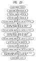
- the posture control motor 44 is turned ON. Then, after the data n0 step stored in a ROM of a control device (not shown) is elapsed from an ON signal of the posture control sensor 43, the posture control motor 44 is stopped. At this point, the developing cartridges D assume the postures wherein the respective developing portions 20 are oriented upwardly as shown in Fig. 19. Then, when the developing operation with different color toner is performed, the rotation (revolution) change (switching) motor 87 is rotated, and the developing cartridge D selected on the basis of the signal of the rotation (revolution) position sensor 88 is shifted to the developing position. Then, the posture control motor 44 is rotated. After the data n1 step stored in the ROM of the control device (not shown) is elapsed, the posture control motor 44 is stopped, thereby attaining the inclined developing postures of the developing cartridges D (Fig. 17).
- the rotation change motor 87 of Fig. 16 is rotated, thereby starting the rotation change operation.
- the posture control motor 44 of Fig. 18 is rotated, thereby shifting the developing cartridges D from a horizontal developing posture shown in Fig. 21A to an upwardly oriented posture shown in Fig. 21B. This shifting is detected by the posture control sensor 43.
- the posture control motor 44 is stopped. At this point, the developing cartridges D assume the upwardly oriented postures, thereby returning the toner from each developing portion 20 to each toner containing portion 19 once.
- the posture control motor 44 is rotated again, thereby shifting the developing cartridges D to a downwardly oriented posture shown in Fig. 21C, so that the toner is fed from each toner containing portion 19 to each developing portion 20 (after n1 step is elapsed, the motor 44 is stopped). Then, the posture control motor 44 is rotated again, and, after n2 step is elapsed, the motor 44 is stopped again, thereby returning the developing cartridges D to the horizontal developing posture shown in Fig. 21A. Then, the rotation change motor 87 is turned ON to shift the desired developing cartridge S to the developing position. Then, the rotation change motor 87 is stopped.
- a toner residual amount detection sensor for detecting the residual amount of toner in the toner containing portion 19 of the developing device 12 of the developing cartridge D is turned ON, the posture control motor 44 of Fig. 18 is rotated to rotate the developing cartridge D by one revolution or more from a horizontal posture shown in Fig. 25A to a downwardly oriented posture shown in Fig. 25B.
- the toner remaining in the toner containing portion 19 can be fed to the developing portion 20, thereby effectively utilizing the toner.
- each developing cartridge D may be not effected by mere rotation of the developing cartridge, but may be effected by repeating the normal and reverse rotations of the developing cartridge from the downwardly oriented posture shown in Fig. 25B, thereby feeding the toner from the toner containing portion 19 to the developing portion 20.
- a gear 34 of the image forming apparatus is meshed with a gear 33 provided on a developer bearing member 15 of a developing device 12 through an opening portion 13b of a support container 13 of the developing device 12, thereby driving the developing device by a drive source 35 of the image forming apparatus.
- a developing cartridge switching mechanism comprises holding members 108, a supporting side plate of Fig. 16, and four connection members 91 connecting the holding members and the side plate.
- Each developing cartridge D is held by a gear 10 having a recessed member 11 into which a rotary support shaft 14 of the support container 13 is fitted and the connection members 91 at the side of the supporting side plate 7, and is held by a sheet member 47 tensioned by springs 46 in front of developing cartridge containing recesses 108b of the holding member 108 at the side of the holding member 108 as shown in Fig. 27.
- the developing cartridge D can be positioned with respect to the image bearing member 1 by the sliding movement.
- a coupling member 48 is arranged on each of developing device revoluting drive gears 10 mounted on a supporting side plate 7 of a developing cartridge switching mechanism so that the coupling member can be rotated integrally with the corresponding gear 10 and can be slidable with respect to the gear 10.
- a rotary support shaft 14 of each developing device 12 is fitted in a hole 48a of the corresponding coupling member 48, thereby permitting the rotational movement of the developing device 12 and the sliding movement of the developing cartridge D toward the image bearing member 1.
- a spring 50 is wound around each coupling member 48 and serves to return the slidingly shifted developing cartridge D and to hold the respective coupling member 48 at a predetermined position on the corresponding gear 10 to thereby facilitate the fitting of the rotary support shaft 14 of the developing device 12 during the mounting of the developing cartridge switching mechanism.
- a developing cartridge holding mechanism as shown in Figs. 31A and 31B is provided on a holding member 108 of developing cartridge switching mechanism, and, as shown in Figs. 30 and 32, a hook 51 is formed on a developing cartridge D in correspondence to the developing cartridge holding mechanism.
- the developing cartridge holding mechanism comprises a hook arm 55, a stopper pin 56 disposed at a rotational center of the arm 55, a pressure spring 57 for urging the pin 56, a return spring 59 for returning the hook arm 55, and a lid member 52 for attaching the mechanism to the holding member 108.
- the stopper pin 56 is non-rotatable with respect to the holding member 108 but is slidable along the pressure spring 57.
- the pin 56 is provided with a projection 58 which is fitted in a recess formed in the hook arm 55 in a condition shown in Figs. 31A and 31B, thereby preventing the rocking movement of the hook arm 55.
- the hook arm 55 is provided with a hole 60 by which the hook 51 of the developing cartridge D is engaged, thereby fixing the developing cartridge D to the holding member 108 via the hook arm 55.
- a cam (not shown) is provided on the side plate 100 of the image forming apparatus at the developing position, in correspondence to the stopper pin 56 of the hook arm 55 holding the developing cartridge D positioned at the developing position.
- the hook arm 55 is disengaged from the pin 56 to permit the rotation of the hook arm 55, thereby permitting the sliding movement of the developing cartridge D toward the image bearing member 1 via the hook arm 55.
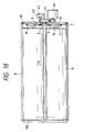
- each developing cartridge D comprises a developing device 210 integrally including a toner containing portion 210a containing toner (one-component developer) T and a developing portion 210c having a developing sleeve 210b to which the toner is supplied from the toner containing portion 210a, a substantially cylindrical support container 211 having an opening portion 211a at its peripheral surface and adapted to contain the developing device 210 and to support the developing device for relative rotational movement around an axis parallel to a rotary shaft of the developing sleeve 210b, and a lock member 212 shiftably held in the proximity of a center of an end face of the developing device 210 and always biased by a spring member 213 radially outwardly of the developing device 210.
- a circular hole is formed in an end face of the support container 211, which circular hole is provided with a notch 211b into which a pawl 212b (Fig. 38) of the lock member 212 is fitted as shown in Fig. 33.
- the developing cartridge D is not mounted to the image forming apparatus, by fitting the pawl 212b of the lock member 212 in the notch 211b by a biasing force of the spring member 213, the developing device 210 is engaged by the support container 211 to lock them in the non-rotating condition, and, as shown in Fig. 33, the developing device 210 is positioned out of phase with the opening portion 211a of the support container 211. That is to say, in this case, the developing sleeve 210b is covered by the peripheral wall of the support container 211, thereby preventing the scattering of toner and the damage of the developing sleeve 210b.
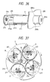
- a developing cartridge switching mechanism S comprises a developing cartridge rotation supporting member 215 having a four-leaf clover cross-section including four semi-circular chambers, and developing device posture control members 214 each arranged at one end (front end in a developing cartridge inserting direction) of the corresponding chamber. Further, developing cartridge supporting portions 216 each comprising a hollow projection are arranged within the developing device posture control members 214. By fitting a boss 210d of the developing device 210 of the developing cartridge D into the hole of the supporting portion 216, the developing cartridge D is held on the supporting member 215 at a predetermined posture (orientation).
- each posture control member 214 is arranged on the end face of the rotation supporting member 215 for shifting movement in the same direction as mentioned above.
- a spring 217 is wound around each posture control member 214 so that, after the development, the posture control member 214 at the developing position is returned to its original position away from the image bearing member 1 by the spring 217.
- a pressure member 218 for urging the developing cartridge D toward the image bearing member 1 at the developing position is non-rotatably secured to a rotary shaft 215a of the developing cartridge supporting member 215.
- the fitting boss 210d formed on the front (in the inserting direction) end of the developing device 210 is fitted in the developing cartridge supporting portion 216, and then a lock release projection 214a of the posture control member 214 urges an arm portion 212a of the lock member 212 in opposition to an elastic force of the spring 213 to displace the lock member 212 radially inwardly to thereby disengage it from the notch 211b, thus releasing the locking condition between the developing device 210 and the support container 211 due to the pawl 212b of the lock member 212. Accordingly, thereafter, when the operator rotates the support container 211 with respect to the developing device 210 in a direction X in Fig. 34 via a grip 211e (Fig.
- the developing sleeve 210b of each developing cartridge D is always directed radially outwardly.
- two or more guiding projections 211c, fitting holes 200b and fitting holes 215a may be provided on the support container 211 of the developing cartridge D, an insertion opening 200a of a side plate 200 of the image forming apparatus and the developing cartridge supporting member 215, respectively, along their peripheries at two or more points, thereby preventing the wrong insertion of the developing cartridge D.
- the developing sleeve 210b is exposed by rotating the support container 211 after the developing cartridges D are mounted to the image forming apparatus, since the positions of the projections 211c of the support container 211 are offset from the positions corresponding to the fitting holes 200b, even if the developing cartridge D tries to be dismounted from the rotation supporting member 215 in this condition, the cartridge cannot be removed from the supporting member because of the mechanical interference between the projections 211c and the inner surface of the side plate 200. That is to say, so long as the support container 211 is rotated in a direction opposite to the direction X to cover the developing sleeve 210b by the peripheral surface of the support container 211, the developing cartridge D cannot be removed from the supporting member 215.
- the exchange of the developing cartridge D can be effected by performing the above operations reversely.
- the support container 211 is rotated in a reverse direction to cover the developing sleeve 210b by the peripheral surface of the support container 211. Then, the developing cartridge D is drawn in a direction opposite to the inserting direction. In this case, before the boss 210d leaves the developing cartridge supporting portion (fitting hole) 216 of the posture control member 214, the arm portion 212a of the lock member 212 is disengaged from the lock releasing projection 214a.
- the lock member 212 is fitted into the notch 211b of the support container 211 by the biasing force of the spring 213, thereby interlocking the developing device 210 and the support container 211. Thereafter, the boss 210d leaves the fitting hole 216 of the posture control member 214, and then the developing cartridge D is retracted from the image forming apparatus.
- the developing cartridge D and the switching mechanism for the developing cartridges are constructed as mentioned above, when the developing cartridge D is dismounted from the image forming apparatus or when a new developing cartridge D is mounted to the image forming apparatus, since the developing sleeve 210b of the developing device 210 is always covered by the support container 210 and since the developing sleeve 210b is exposed only when the developing cartridge D is held by the rotation supporting member 215 in the predetermined posture, it is possible to prevent the toner contamination and the damage of the developing sleeve 210b. Further, since the locking condition of the developing device 210 with respect to the support container 211 can be released only by inserting developing cartridge D into the image forming apparatus, the operability for mounting the developing cartridge D can be improved.
- Fig. 41 is a front view of a developing cartridge switching mechanism according to an eleventh embodiment of the present invention.
- a developing cartridge switching mechanism S' comprises a posture control portion 220, and a rotation supporting member 221.
- the posture control portion 220 comprises a central sun gear 222 secured to a rotary shaft 221a of the rotation supporting member 221, posture control gears 224 provided at mounting positions of developing cartridges, and idler gears 223 disposed between the sun gear 222 and the posture control gears 224 and meshed with these gears.
- developing cartridge supporting members 225 similar to the posture control members 214 shown in Figs.
- a return spring 226 for applying a biasing force in the same direction as mentioned above is arranged on the corresponding developing cartridge supporting member 225 to return the developing cartridge D to its original position away from the image bearing member 1 after the development.
- a pressure member 227 for urging the developing cartridge D toward the image bearing member 1 is non-rotatably secured to the rotary shaft 221a of the rotation supporting member 221.
- the sun gear 222 and the posture control gears 224 have the same number of teeth. Since the sun gear 222 is secured to the rotary shaft 221a, when the posture control portion 220 and the rotation supporting member 221 are integrally rotated, the posture control gears 224 are shifted around the rotary shaft 221a without changing the postures thereof. Thus, the supporting members 225 arranged on the gears 224 are always oriented in the constant direction.
- the locking condition between the developing device 210 of Fig. 33 and the support container 211 is released. Further, in this mounting condition, since the developing cartridge D is positioned so that the developing device 210 is opposed to the image bearing member 1 and the opening portion 211a of the support container 211 is aligned with the developing portion 210c and since such posture does not change during the rotation of the switching mechanism S', the inserting operation of the developing cartridge D can be simplified, and a bad influence such as the concentration of toner in the proximity of the developing sleeve (developer bearing member) and the developing blade (toner thickness regulating member) can be eliminated. Further, at any position other than the developing position, since the opening portion 211a of the support container 211 is not aligned with the developing portion, the leakage of toner can be prevented.
- posture control gears 224 of the posture control portion 220 in the above eleventh embodiment explained in connection with Fig. 41 in place of the posture control gears 224 of the posture control portion 220 in the above eleventh embodiment explained in connection with Fig. 41, as shown in Fig. 42, posture control gears 224' on which developing cartridge supporting members 225' are directly formed are used, and a slot 225a having the same length as the shifting amount of the developing cartridge D at the developing position is formed in each developing cartridge supporting members 225'.
- the return springs can be omitted.
Abstract
Description
- The present invention relates to a developing apparatus and a developing cartridge used with an image forming apparatus such as a copying machine, a printer and the like and particularly used with a color image forming apparatus.
- In full-color image forming apparatuses, a developing unit including an yellow developing device, a magenta developing device, a cyan developing device and a black developing device is rotated to face a selected developing device to an image bearing member.
- When such a developing unit is rotated, since it is feared that developer leaks from the unit or the developer is scattered, it is desirable to prevent postures or attitudes of the developing devices from changing.
- Further, at a connection portion between each developing device and its developer replenishing portion, since the separation and connection are effected in order to switch the developing devices for developing a latent image formed on the image bearing member, the developer was particularly apt to be leaked. Further, in order to exchange a developing device a service life of which was expired, such a developing device must be exchanged by a new one by an expert and the maintenance must also be performed by the expert. To avoid this, it is considered that each of the developing devices is made as a cartridge.
- However, when the postures of the developing devices are maintained in a steady condition, since the developing devices are rotated with respect to the developing unit, it is necessary to provide peripheral gaps between the developing devices and the developing unit. In this case, it is difficult to mount the developing cartridges on the developing unit with the peripheral gaps.
- A concern of the present invention is to provide a developing apparatus in which a plurality of developing devices are made as respective cartridges.
- Another concern of the present invention is to provide a developing apparatus in which developing devices can be shifted while maintaining postures thereof in a steady condition.
- A further concern of the present invention is to provide a developing cartridge which can be easily mounted.
- An embodiment of the present invention provides a developing cartridge comprising a containing portion for containing developer, a developing device having a bearing member for bearing or carrying the developer, a support member adapted to rotatably support the developing device and having an opening portion, and lock means for locking the rotation of the developing device with respect to the support member at a position where the bearing member is out of the opening portion.
- Another embodiment of the present invention provides a developing apparatus comprising a developing cartridge including a rotatable developing unit, a containing portion for containing developer, a developing device having a bearing member for bearing or carrying the developer, and a support member having an opening portion and adapted to rotatably support the developing device and supported non-rotatably with respect to the developing unit; and a rotation means for rotating the developing device with respect to the support member when the developing unit is rotated.
- Other concerns of the present invention will be apparent from the following detailed explanation.
-
- Fig. 1 is a sectional view showing the entire construction of an image forming apparatus having a developing cartridge according to the present invention;
- Fig. 2 is a perspective view showing a method for mounting a drum cartridge and a waste toner container provided in the image forming apparatus of Fig. 1;
- Fig. 3 is a perspective view of the drum cartridge;
- Fig. 4 is a perspective view showing a condition that a protection member is removed when the drum cartridge is mounted;
- Fig. 5 is an end view of the drum cartridge;
- Fig. 6 is a sectional view showing a condition that an eccentric member is provided on a central shaft of an image bearing member arranged in the drum cartridge;
- Fig. 7 is a side view, partially in section, showing a method for mounting a switching mechanism for switching a developing cartridge arranged in the image forming apparatus of Fig. 1 onto a holding member;
- Fig. 8 is a sectional view of the developing cartridge of Fig. 7;
- Fig. 9 is a front view showing a developing device drive mechanism and a side plate of the developing cartridge switching mechanism;
- Fig. 10 is a sectional view of a developing cartridge of an image forming apparatus according to a second embodiment of the present invention;
- Fig. 11 is a perspective view of the developing cartridge of Fig. 10;
- Fig. 12 is a sectional view showing a method for securing a developing device of the developing cartridge to a support container;
- Figs. 13A and 13B are sectional views showing a condition that the securing is being released by mounting the developing cartridge onto a holding member;
- Fig. 14 is a front view showing a developing cartridge holding member and a developing cartridge mounted to the holding member in an image forming apparatus according to a third embodiment of the present invention;
- Fig. 15 is a side view, partially in section, showing a method for mounting a developing cartridge to a holding member in an image forming apparatus according to a fourth embodiment of the present invention;
- Fig. 16 is a front view showing a developing device drive mechanism and a side plate of a developing cartridge switching mechanism;
- Fig. 17 is a sectional view showing a method for driving a driven portion of the developing cartridge and the developing cartridge switching mechanism;
- Fig. 18 is a front view of another posture control mechanism provided in the developing cartridge switching mechanism;
- Fig. 19 is a front view of the developing cartridge a posture of which is oriented upwardly by the control mechanism of Fig. 18;
- Fig. 20 is a control flow chart;
- Figs. 21A to 21C are front views showing a posture control of a developing device of a developing cartridge in an image forming apparatus according to a fifth embodiment of the present invention;
- Fig. 22 is a block diagram of a control mechanism for the posture control;
- Fig. 23 is a control flow chart;
- Fig. 24 is a flow chart showing a method for performing a posture control of a developing cartridge in an image forming apparatus according to a sixth embodiment of the present invention;
- Figs. 25A and 25B are front views showing the change in the posture of the developing cartridge effected by the control of Fig. 24;
- Fig. 26 is a front view of a developing cartridge and a switching mechanism therefor in an image forming apparatus according to a seventh embodiment of the present invention;
- Fig. 27 is a front view showing a condition that a sheet member is mounted on a holding member of the developing cartridge switching mechanism;
- Fig. 28 is a front view showing a developing device drive mechanism supporting side plate of a developing cartridge switching mechanism in an image forming apparatus according to an eighth embodiment of the present invention;
- Fig. 29 is a side view showing a condition that a rotary shaft of a developing device of a developing cartridge is being fitted in a coupling member provided on the side plate of Fig. 28;
- Fig. 30 is a front view showing a condition that a developing cartridge switching mechanism is secured to a holding member in an image forming apparatus according to a ninth embodiment of the present invention;
- Figs. 31A and 31B are views showing a developing cartridge holding mechanism for performing the securing of Fig. 30;
- Fig. 32 is a side view of a securing hook provided on a developing cartridge;
- Fig. 33 is a front view of a developing cartridge in an image forming apparatus according to a tenth embodiment of the present invention;
- Fig. 34 is a front view showing a condition that a developing posture of the developing cartridge of Fig. 33 is achieved after the cartridge is mounted on a switching mechanism of the image forming apparatus;
- Fig. 35 is a perspective view of the developing cartridge of Fig. 33;
- Fig. 36 is a perspective view showing a condition that the developing cartridge of Fig. 33 is being mounted on a rotary member of the developing cartridge switching mechanism;
- Fig. 37 is a front view of the switching mechanism on which the developing cartridge of Fig. 33 is mounted;
- Fig. 38 is a side view showing a condition that the developing cartridge of Fig. 33 is being mounted on the rotary member of the developing cartridge switching mechanism;
- Fig. 39 is a side view showing a condition that a lock member of the developing cartridge is unlocked by the mounting of Fig. 38;
- Fig. 40 is a side view showing another example of a posture control mechanism;
- Fig. 41 is a front view of a developing cartridge switching mechanism in an image forming apparatus according to an eleventh embodiment of the present invention; and
- Fig. 42 is a front view of a developing cartridge switching mechanism in an image forming apparatus according to a twelfth embodiment of the present invention.
- Fig. 1 is a sectional view of an image forming apparatus having a developing apparatus according to a first embodiment of the present invention. The image forming apparatus comprises a drum cartridge C removably mountable to the image forming apparatus and including an
image bearing member 1, acharge member 2 and acleaner 3; a plurality of developing cartridges D (yellow developing cartridge Dy, magenta developing cartridge Dm, cyan developing cartridge Dc and black developing cartridge Db) each including a developing portion having a developer bearing member and a toner containing portion containing toner (one-component developer) and each removably mountable to the image forming apparatus independently; a developing unit to which the developing cartridges D are removably mounted; and a developing cartridge switching mechanism for rotating the developing unit to bring a selected developing device to a developing position opposed to theimage bearing member 1. - According to this image forming apparatus, a latent image for each color is formed on the
image bearing member 1 of the drum cartridge C by image exposure by means of anoptical unit 107, and the developing cartridge D corresponding to this color is brought, by the switching mechanism, to the latent image, thereby developing the latent image. Images having various colors obtained by such developing operations are successively transferred onto asheet 102 held by atransfer drum 103 in a superposed fashion. Thesheet 102 is supplied from asheet supply portion 101, and a tip end of the sheet is gripped by agripper 103f of thetransfer drum 103, so that the sheet is mounted around the transfer drum as the transfer drum is rotated. Thesheet 102 to which the toner images were transferred is separated from thetransfer drum 103 and then is sent to afixing unit 104, where the toner images are mixed and fixed to the sheet. Thereafter, the sheet is discharged onto adischarge tray 106 through asheet discharge portion 105. - Next, the drum cartridge C will be explained with reference to Figs. 2 to 6. As shown in Fig. 2, the drum cartridge C is mounted between a pair of side plates 100 (a front side plate alone is shown) in the image forming apparatus by inserting the drum cartridge into mounting
openings 100a of the side plates from outside of one of theside plates 100 in a thrust direction (perpendicular to the surface of the side plate 100). In this way, the drum cartridge C is removably mountable to the image forming apparatus in the thrust direction. - A
waste toner container 4 is attached to one end of the drum cartridge D protruded from theside plate 100, and a notched portion 4a to be fitted onto acover 81 for covering an exposedcentral shaft 22 of theimage bearing member 1 is formed in an upper portion of thewaste toner container 4. The notched portion 4a and thecover 81 serve as guides when thewaste toner container 4 is mounted to the drum cartridge C. - An opening (not shown) for permitting the mounting and dismounting of the drum cartridge C and the
waste toner container 4 with respect to the image forming apparatus is formed in a front outer plate (not shown) of the image forming apparatus. - As shown in Figs. 3 and 5, the drum cartridge C is provided at its both ends with plate-shaped
frame portions 21, and the cylindricalimage bearing member 1 is rotatably supported between lower portions of theframe portions 21. - Before the drum cartridge C is mounted to the image forming apparatus, a semi-circular lower portion of the drum cartridge is covered by a
protection member 6 for protection. Theprotection member 6 has a semi-cylindrical shape having an open top. The protection member is attached to the drum cartridge C along a longitudinal direction by inserting protrudedportions 6a formed on both upper ends of the opening of the semi-circular cylinder of the protection member into correspondingnotch recesses 21a formed in theframe portions 21 of the drum cartridge C. When the drum cartridge C is mounted on theside plates 100, as the drum cartridge C is inserted into the mountingopening 100a, as shown in Fig. 4, aframe portion 6a formed on a front (regarding an insertion direction of the cartridge) end of theprotection member 6 is abutted against theside plate 100, thereby removing theprotection member 6 from the drum cartridge C. - As shown in Fig. 6 (where the
front frame portion 21 is omitted from illustration), the drum cartridge C includes theimage bearing member 1, acharge member 2 for charging the image bearing member, and acleaner 3 for removing toner from the image bearing member (cleaning member 3a, agitatingmember 3b for agitating the removed toner, andtoner feed screw 3c for sending the toner to the waste toner container 4). Further,positioning members side plate 100 are provided on the (front)frame portion 21 near thewaste toner container 4. - As shown in Fig. 1, the developing cartridge switching mechanism comprises a pair of plate-shaped developing
cartridge holding members 108 rotatable around a non-rotatablecentral shaft 110 parallel to the shaft of theimage bearing member 1, anarcuated guide member 112 secured to the image forming apparatus and surrounding the holding members except for areas where the drum cartridge C and thetransfer drum 103 are positioned, apressure member 111 for urging the selected developing cartridge D toward theimage bearing member 1 of the drum cartridge C at the developing position, a drive source for rotating thepressure member 111 for effecting such urging, a positioning member for positioning the developing cartridge D at a predetermined position with respect to theimage bearing member 1, and a control mechanism for maintaining each developing cartridge D in a predetermined posture. - Each holding
member 108 has a shape of a four-leaf clover being provided along its periphery with containing recesses (each comprising substantially semi-circular notched portion) 108b for receiving the corresponding developing cartridges D. As shown in Fig. 7, each developing cartridge D is mounted between the holdingmembers 108 by inserting the cartridge into the pair of containingrecesses 108b of the holdingmembers 108 while being guided by theguide member 112 at a position other than the developing position opposed to theimage bearing member 1. Further, each developing cartridge D can be removed from the holdingmembers 108. In this way, the developing cartridges D of different colors are removably and independently mounted on the switching mechanism and accordingly the image forming apparatus in the thrust direction. Further, openings (not shown) for permitting the mounting and dismounting of the developing cartridges D with respect to the image forming apparatus are formed in the front outer plate (not shown) of the image forming apparatus. - As shown in Fig. 8, the developing cartridge D comprises a developing
device 12, and a pair ofdishshaped support plates 83 for rotatably supporting the developingdevice 12 viarotary support shafts 14 secured to both ends of thedevice 12. The rear (that side)rotary support shaft 14 extends through one of thesupport plates 83 and is attached to a control mechanism of a developing cartridge switching mechanism which will be described later. - The developing
device 12 is generally divided into atoner containing portion 19 and an adjacent developingportion 20. An agitating conveymember 18 for agitating the toner and for conveying the toner to the developingportion 20 is arranged in thetoner containing portion 19. On the other hand, adeveloper bearing member 15, a supply andscrape member 17 for supplying the toner to the developer bearing member and for scrape the non-developed toner from the developer bearing member, and a regulatingmember 16 for regulating a thickness of a toner layer carried on thedeveloper bearing member 15 and for applying the electric charge to the toner are arranged in the developingportion 20. -
Leg portions 83a corresponding tosteps 108a formed in the containingrecesses 108b of the holdingmember 108 shown in Fig. 1 are provided on both sides of both ends of eachsupport plate 83, so that thesupport plates 83 of the developing cartridge D contained in the containingrecesses 108b are non-rotatably held with respect to the holdingmembers 108 by abutting theleg portions 83a against thesteps 108a. When the developing cartridge D is positioned at the developing position, theleg portions 83a serve as guides for shifting the developing cartridge D toward theimage bearing member 1. - Each developing cartridge D is inserted into and mounted within the containing recesses 108b in the holding
members 108 in such a manner that the developingdevice 12 keeps a predetermined posture, i.e., in the illustrated embodiment, thetoner containing portion 19 and the developingportion 20 are disposed side by side in a horizontal direction (i.e., apartition wall 12a between thetoner containing portion 19 and the developingportion 20 is oriented vertically) and thus aparallel portion 14a of therotary support shaft 14 is disposed horizontally. - As shown in Fig. 1, the developing cartridge switching mechanism is provided with a control mechanism for maintaining the developing
device 12 of each developing cartridge D shifted to the developing position by the rotation of the holdingmembers 108 in a predetermined unchanged posture. As shown in Figs. 7 and 9, the control mechanism has a plate-shaped developing device drive mechanism supportingside plate 7 rotated integrally with the holdingmember 108 around the non-rotatablecentral shaft 110 of the holdingmember 108. Pairs ofgears device 12 are arranged on an inner surface of theside plate 7 in correspondence to the respective developing cartridges D. Further, agear 8 is non-rotatably secured to thecentral shaft 110 and is meshed with thegears 9, so that a planetary gear mechanism is constituted by the gears, 8, 9 and 10. A recessedmember 11 having aU-shaped recess 11a is attached to a surface (facing the developing cartridge D) of eachgear 10. In the illustrated embodiment, in a condition that theU-shaped recesses 11a of the recessedmembers 11 are oriented horizontally as shown in Fig. 9, theparallel portions 14a (now oriented horizontally) of therotary support shafts 14 of the developingdevices 12 of the developing cartridges D mounted on the holdingmembers 108 are fitted into theU-shaped recesses 11a. - According to the above-mentioned control mechanism, when the holding
members 108 are rotated around thecentral shaft 110 toward the developing position to shift the developing cartridges D, the supportingside plate 7 is also rotated in the same direction, thereby causing the planetary movement of thegears members 11 of the supportingside plate 7 are rotated in reverse or opposite directions to maintain theU-shaped reverses 11a in horizontal conditions. Accordingly, the developingdevices 12 fitted in the U-shaped recesses via therotary support shafts 14 are also rotated in the reverse directions (same as the recessed members 11) in the developing cartridge D, so that the developingdevices 12 are always maintained in the horizontal conditions, regardless of the movement of the developing cartridges D. - If necessary, when the
central shaft 110 of the holdingmembers 108 is rotated by an appropriate drive source (not shown), any postures (for example, inclined postures) of the developingdevices 12 in the developing cartridges D can be achieved. In this way, by slidingly inserting thesupport plates 83 each having a diameter greater than an outer diameter of the developing cartirdge D into the containingrecesses 108b of the holdingmembers 108, the developing cartridge can easily be mounted on the holding members, and, since there are gaps between the developing device and the containing recesses, the developing device can freely be rotated. - Next, a second embodiment of the present invention will be explained with reference to Figs. 10 to 13B.
- As shown in Fig. 10, in this embodiment, a developing cartridge D comprises a developing
device 12, and acylindrical support container 13 for rotatably containing the developingdevice 12 viarotary support shafts 14 secured to both ends of the developing device. The rear (that side)rotary support shaft 14 protrudes from an end face of the developingdevice 12 and is attached to the control mechanism of the developing cartridge switching mechanism as shown in Fig. 9, as is in the first embodiment. -
Leg portions 13a corresponding to thestep 108a formed in the containingrecesses 108b of the holdingmember 108 shown in Fig. 1 are provided on both sides of both ends of thesupport container 103, so that thesupport container 13 of the developing cartridge D contained in the containingrecesses 108b is non-rotatably held with respect to the holdingmembers 108 by abutting theleg portions 13a against thesteps 108a. - An
opening portion 13b is formed in a portion of thesupport container 103 opposite to theleg portions 13a so that adeveloper bearing member 15 of the developingdevice 12 in thesupport container 13 can be opposed to theimage bearing member 1 when the developing cartridge D is shifted to the developing position. At the developing position opposed to theimage bearing member 1, the transmission of a driving force and the electrical connection to thedeveloper bearing member 15 of the developingdevice 12 can be effected through theopening portion 13b. Of course, another opening may be formed in thesupport container 13 and such transmission and connection may be effected through such another opening. - As is in the first embodiment, each developing cartridge D is contained in and mounted to the containing
recesses 108b of the holdingmembers 108 by fitting theparallel portion 14a of therotary support shaft 14 into theU-shaped recess 11a of the recessedportion 11 provided on the inner surface of the supportingside plate 7 of the control mechanism of the developing cartridge switching mechanism shown in Fig. 9. With this arrangement, the developing cartridges D of different colors can be shifted successively to the developing position opposed to theimage bearing member 1; meanwhile, the developing devices are always maintained in predetermined postures, regardless of the movement of the developing cartridges D. In the developing cartridge S positioned in the developing position, thedeveloper bearing member 15 of the developingdevice 12 is opposed to theimage bearing member 1 through theopening portion 13b of thesupport container 13. - According to this embodiment, when the developing cartridges D are mounted to or dismounted from the image forming apparatus or when the developing cartridge D alone is treated or handled, in order to prevent the developing
portion 20 of the developingdevice 12 from exposing through theopening portion 13b of thesupport container 13, as shown in Fig. 12, the developingportion 20 of the developingdevice 12 is fixed at a non-exposed position opposite to theopening portion 13b of thesupport container 13 by a holding mechanism. And, in such a non-exposed condition, the developing cartridge D is mounted to or dismounted from the holdingmembers 108, and the developing cartridge D alone is stored in such a non-exposed condition before it is mounted to the holdingmembers 108. - As shown in Fig. 12, the holding mechanism comprises a downwardly directing
pin 62 provided at a lower portion of the developingdevice 12 of the developing cartridge D, aspring 63 for biasing thepin 62 downwardly, and a notchedportion 64 provided in the proximity of one of theleg portions 13a of thesupport container 13. When the developing cartridge D is not mounted to the image forming apparatus, thepin 62 is fitted into the notchedportion 64, thereby non-rotatably fixing the developingportion 20 of the developingdevice 12 in the non-exposed position in thesupport container 13. - As shown in Fig. 13A, when the developing cartridge D is mounted in the containing
recesses 108b of the holdingmembers 108, as shown in Fig. 13B, the notchedportion 64 of thesupport container 13 is fitted on a protrudedportion 108c of the holdingmember 108, thereby retracting thepin 62 of the developingdevice 12 upwardly from the notchedportion 64 by the protrudedportion 108c. As a result, the developing cartridge D mounted to the holdingmembers 108 can be rotated with respect to thesupport container 13. - Fig. 14 is a front view showing a developing
cartridge holding member 108 and a developing cartridge mounted to the holding member, according to a third embodiment of the present invention. - In this embodiment, semi-circular and/or rectangular
key ways 65 are formed in the developingcartridge containing recesses 108b of the holdingmember 108 in such a manner that the shape or the number of thekey ways 65 is different from the containing recess to the containing recess. On the other hand, key orkeys 66 having the shape or number corresponding to the key way(s) 65 formed in the corresponding containingrecess 108b are formed on thesupport container 13 of the developing cartridge D to be inserted into such containing recess. - By judging whether the key(s) 66 can be fitted into the key way(s) 65 or not, it is possible to insert a specific developing cartridge D into the corresponding containing
recess 108b, thereby mounting the former to the latter. Further, since thesupport container 13 does not rotate, when the developing cartridge D is dismounted from the holdingmembers 108, it is nor required for performing the registration between the key way(s) 65 and the key(s) 66. - Next, a fourth embodiment of the present invention will be explained.
- Fig. 15 is a side view, partially in section, showing a method for mounting a developing cartridge, according to the fourth embodiment of the present invention. The whole construction of this fourth embodiment is fundamentally the same as that of the first embodiment.
- In this fourth embodiment, as is in the second embodiment, as shown in Fig. 10, a developing cartridge D comprises a developing
device 12, and acylindrical support container 13 for rotatably containing the developingdevice 12 viarotary support shafts 14 secured to both ends of the developing device. As shown in Fig. 15, the developing cartridge D is mounted on the holdingmembers 108 of the developing cartridge switching mechanism by inserting the developing cartridge into the containingrecesses 108b of the holdingmembers 108. - As shown in Fig. 16, the developing cartridge switching mechanism comprises a plate-shaped developing device drive mechanism supporting
side plate 7 rotated integrally with the holdingmember 108 around the non-rotatablecentral shaft 110 of the holdingmember 108. As shown in Figs. 15 and 16, agear 85 for driving the supportingside plate 7 is provided on an outer surface of theside plate 7. The supportingside plate 7 is driven by a cartridge shifting motor (rotation switching motor) 87 via agear 86 meshed with thegear 85. - As is in the first embodiment, gears 9, 10 which are meshed with each other and a
gear 8 secured to thecentral shaft 110 and meshed with thegears 9, which constitute a drive mechanism for the developingdevice 12 are arranged on an inner surface of theside plate 7. A planetary gear mechanism for controlling postures of the developingdevices 12 is constituted by thesegears rotary support shafts 14 protruded from thesupport containers 13 of the developingdevices 12 are fitted intoU-shaped recesses 11a of recessedmembers 11 formed on therespective gears 10, by rotating the developingdevices 12 by means of the planetary gear mechanism, the postures of the developingdevices 12 are controlled. - As shown in Fig. 17, when one of the developing cartridges D is positioned at the developing position opposed to the
image bearing member 1, agear 34 of the image forming apparatus is meshed with agear 33 provided on thedeveloper bearing member 15 of the developingdevice 12 through theopening portion 13b of thesupport container 13 of the developingdevice 12, thereby driving the developing device by a drive source 32 of the image forming apparatus. In this case, a flag (revolution position flag) 89 for detecting the revolution position of the developing cartridge D is provided on the holdingmember 108, and arevolution position sensor 88 associated with therevolution position flag 89 is arranged in the image forming apparatus. When the developing cartridge D is changed, by detecting the passage of therevolution position flag 89 by therevolution position sensor 88, a given developing cartridge D is shifted to the developing position or to a developingcartridge exchanging opening 90 formed in the outer plate of the image forming apparatus, on the basis of the detected position as a reference. - As shown in Fig. 18, a gear 41 secured to a gear shaft of the central gear 8 (forming a part of the planetary gear mechanism for effecting the posture control of the developing devices 12) of the supporting
side plate 7 is rotated together with thecentral gear 8, and this gear 41 is driven by a motor (posture control motor) 44. The gear 41 is provided with aflag 42 for providing a reference for the posture control in correspondence to the stop position of the gear 41, whichflag 42 is detected by a posture control sensor 43 arranged in the image forming apparatus. The postures of the developing cartridges are controlled in such a manner that the developing cartridges D are inclined by a given angle toward theirtoner containing portions 19 in the developing operation as shown in Fig. 17, and the developingportions 20 including theirdeveloper bearing members 15 are oriented upwardly in the revolutional switching operation during the non-developing operation as shown in Fig. 19, thereby preventing the leakage and scattering of the toner. - As shown in a flow chart of Fig. 20, after the developing operation is finished, the posture control motor 44 is turned ON. Then, after the data n₀ step stored in a ROM of a control device (not shown) is elapsed from an ON signal of the posture control sensor 43, the posture control motor 44 is stopped. At this point, the developing cartridges D assume the postures wherein the respective developing
portions 20 are oriented upwardly as shown in Fig. 19. Then, when the developing operation with different color toner is performed, the rotation (revolution) change (switching)motor 87 is rotated, and the developing cartridge D selected on the basis of the signal of the rotation (revolution)position sensor 88 is shifted to the developing position. Then, the posture control motor 44 is rotated. After the data n₁ step stored in the ROM of the control device (not shown) is elapsed, the posture control motor 44 is stopped, thereby attaining the inclined developing postures of the developing cartridges D (Fig. 17). - Next, a fifth embodiment of the present invention will be explained with reference to Figs. 21A - 21C, 22 and 23.
- In this embodiment, after the development with the first color is finished, as shown in a flow chart of Fig. 23, the
rotation change motor 87 of Fig. 16 is rotated, thereby starting the rotation change operation. Then, the posture control motor 44 of Fig. 18 is rotated, thereby shifting the developing cartridges D from a horizontal developing posture shown in Fig. 21A to an upwardly oriented posture shown in Fig. 21B. This shifting is detected by the posture control sensor 43. Then, after the data n₀ step stored in a ROM shown in Fig. 22 is elapsed, the posture control motor 44 is stopped. At this point, the developing cartridges D assume the upwardly oriented postures, thereby returning the toner from each developingportion 20 to eachtoner containing portion 19 once. - When the developing cartridges D are shifted to their developing postures again, the posture control motor 44 is rotated again, thereby shifting the developing cartridges D to a downwardly oriented posture shown in Fig. 21C, so that the toner is fed from each
toner containing portion 19 to each developing portion 20 (after n₁ step is elapsed, the motor 44 is stopped). Then, the posture control motor 44 is rotated again, and, after n₂ step is elapsed, the motor 44 is stopped again, thereby returning the developing cartridges D to the horizontal developing posture shown in Fig. 21A. Then, therotation change motor 87 is turned ON to shift the desired developing cartridge S to the developing position. Then, therotation change motor 87 is stopped. - Next, a sixth embodiment of the present invention will be explained with reference to Figs. 24 and 25.
- As shown in a flow chart of Fig. 24, when a toner residual amount detection sensor for detecting the residual amount of toner in the
toner containing portion 19 of the developingdevice 12 of the developing cartridge D is turned ON, the posture control motor 44 of Fig. 18 is rotated to rotate the developing cartridge D by one revolution or more from a horizontal posture shown in Fig. 25A to a downwardly oriented posture shown in Fig. 25B. As a result, the toner remaining in the toner containing portion 19 (not fed by the toner agitating member 18) can be fed to the developingportion 20, thereby effectively utilizing the toner. - Incidentally, the posture control operation of each developing cartridge D may be not effected by mere rotation of the developing cartridge, but may be effected by repeating the normal and reverse rotations of the developing cartridge from the downwardly oriented posture shown in Fig. 25B, thereby feeding the toner from the
toner containing portion 19 to the developingportion 20. - Next, a seventh embodiment of the present invention will be explained with reference to Figs. 26 and 27.
- As shown in Fig. 26, when the developing cartridge D is positioned at the developing position opposed to the
image bearing member 1, agear 34 of the image forming apparatus is meshed with agear 33 provided on adeveloper bearing member 15 of a developingdevice 12 through anopening portion 13b of asupport container 13 of the developingdevice 12, thereby driving the developing device by adrive source 35 of the image forming apparatus. - A developing cartridge switching mechanism comprises holding
members 108, a supporting side plate of Fig. 16, and fourconnection members 91 connecting the holding members and the side plate. Each developing cartridge D is held by agear 10 having a recessedmember 11 into which arotary support shaft 14 of thesupport container 13 is fitted and theconnection members 91 at the side of the supportingside plate 7, and is held by asheet member 47 tensioned bysprings 46 in front of developingcartridge containing recesses 108b of the holdingmember 108 at the side of the holdingmember 108 as shown in Fig. 27. - With this arrangement, by positioning a direction that an opening of a
recess 11a of the recessedmember 11 of thegear 10 is coincident with the opening of the developingcartridge containing recess 108b of the holdingmember 108 toward theimage bearing member 1, as shown in Fig. 27, the developing cartridge D can be positioned with respect to theimage bearing member 1 by the sliding movement. - Next, an eighth embodiment of the present invention will be explained with reference to Figs. 28 and 29.
- As shown in Figs. 28 and 29, a
coupling member 48 is arranged on each of developing device revoluting drive gears 10 mounted on a supportingside plate 7 of a developing cartridge switching mechanism so that the coupling member can be rotated integrally with thecorresponding gear 10 and can be slidable with respect to thegear 10. Arotary support shaft 14 of each developingdevice 12 is fitted in ahole 48a of the correspondingcoupling member 48, thereby permitting the rotational movement of the developingdevice 12 and the sliding movement of the developing cartridge D toward theimage bearing member 1. - Further, a
spring 50 is wound around each couplingmember 48 and serves to return the slidingly shifted developing cartridge D and to hold therespective coupling member 48 at a predetermined position on thecorresponding gear 10 to thereby facilitate the fitting of therotary support shaft 14 of the developingdevice 12 during the mounting of the developing cartridge switching mechanism. - Next, a ninth embodiment of the present invention will be explained with reference to Figs. 30 to 32.
- In this embodiment, a developing cartridge holding mechanism as shown in Figs. 31A and 31B is provided on a holding
member 108 of developing cartridge switching mechanism, and, as shown in Figs. 30 and 32, ahook 51 is formed on a developing cartridge D in correspondence to the developing cartridge holding mechanism. The developing cartridge holding mechanism comprises ahook arm 55, astopper pin 56 disposed at a rotational center of thearm 55, apressure spring 57 for urging thepin 56, areturn spring 59 for returning thehook arm 55, and alid member 52 for attaching the mechanism to the holdingmember 108. - The
stopper pin 56 is non-rotatable with respect to the holdingmember 108 but is slidable along thepressure spring 57. Thepin 56 is provided with aprojection 58 which is fitted in a recess formed in thehook arm 55 in a condition shown in Figs. 31A and 31B, thereby preventing the rocking movement of thehook arm 55. Thehook arm 55 is provided with ahole 60 by which thehook 51 of the developing cartridge D is engaged, thereby fixing the developing cartridge D to the holdingmember 108 via thehook arm 55. - A cam (not shown) is provided on the
side plate 100 of the image forming apparatus at the developing position, in correspondence to thestopper pin 56 of thehook arm 55 holding the developing cartridge D positioned at the developing position. When thepin 56 is pressed down by the cam, thehook arm 55 is disengaged from thepin 56 to permit the rotation of thehook arm 55, thereby permitting the sliding movement of the developing cartridge D toward theimage bearing member 1 via thehook arm 55. - Next, a tenth embodiment of the present invention will be explained with reference to Figs. 33 to 39.
- As shown in Fig. 33, each developing cartridge D comprises a developing
device 210 integrally including atoner containing portion 210a containing toner (one-component developer) T and a developingportion 210c having a developingsleeve 210b to which the toner is supplied from thetoner containing portion 210a, a substantiallycylindrical support container 211 having anopening portion 211a at its peripheral surface and adapted to contain the developingdevice 210 and to support the developing device for relative rotational movement around an axis parallel to a rotary shaft of the developingsleeve 210b, and alock member 212 shiftably held in the proximity of a center of an end face of the developingdevice 210 and always biased by aspring member 213 radially outwardly of the developingdevice 210. - As shown in Fig. 35, a circular hole is formed in an end face of the
support container 211, which circular hole is provided with anotch 211b into which apawl 212b (Fig. 38) of thelock member 212 is fitted as shown in Fig. 33. When the developing cartridge D is not mounted to the image forming apparatus, by fitting thepawl 212b of thelock member 212 in thenotch 211b by a biasing force of thespring member 213, the developingdevice 210 is engaged by thesupport container 211 to lock them in the non-rotating condition, and, as shown in Fig. 33, the developingdevice 210 is positioned out of phase with theopening portion 211a of thesupport container 211. That is to say, in this case, the developingsleeve 210b is covered by the peripheral wall of thesupport container 211, thereby preventing the scattering of toner and the damage of the developingsleeve 210b. - As shown in Figs. 36 and 37, a developing cartridge switching mechanism S comprises a developing cartridge
rotation supporting member 215 having a four-leaf clover cross-section including four semi-circular chambers, and developing deviceposture control members 214 each arranged at one end (front end in a developing cartridge inserting direction) of the corresponding chamber. Further, developingcartridge supporting portions 216 each comprising a hollow projection are arranged within the developing deviceposture control members 214. By fitting aboss 210d of the developingdevice 210 of the developing cartridge D into the hole of the supportingportion 216, the developing cartridge D is held on the supportingmember 215 at a predetermined posture (orientation). - At the developing position opposed to the
image bearing member 1, in order to shift the developing cartridge D toward theimage bearing member 1 to position it with respect to the image bearing member for permitting the development, eachposture control member 214 is arranged on the end face of therotation supporting member 215 for shifting movement in the same direction as mentioned above. Aspring 217 is wound around eachposture control member 214 so that, after the development, theposture control member 214 at the developing position is returned to its original position away from theimage bearing member 1 by thespring 217. On the other hand, apressure member 218 for urging the developing cartridge D toward theimage bearing member 1 at the developing position is non-rotatably secured to arotary shaft 215a of the developingcartridge supporting member 215. - As shown in Figs. 36 and 38, when the developing cartridge D is shifted along an axial direction of the developing
sleeve 210b to be inserted along the rotary shaft of therotation supporting member 215 at a mounting and dismounting position different from the developing position, as shown in Fig. 39, thefitting boss 210d formed on the front (in the inserting direction) end of the developingdevice 210 is fitted in the developingcartridge supporting portion 216, and then alock release projection 214a of theposture control member 214 urges anarm portion 212a of thelock member 212 in opposition to an elastic force of thespring 213 to displace thelock member 212 radially inwardly to thereby disengage it from thenotch 211b, thus releasing the locking condition between the developingdevice 210 and thesupport container 211 due to thepawl 212b of thelock member 212. Accordingly, thereafter, when the operator rotates thesupport container 211 with respect to the developingdevice 210 in a direction X in Fig. 34 via agrip 211e (Fig. 36) of thesupport container 211 to align theopening portion 211a of thesupport container 211 with the developingsleeve 210b of the developingdevice 210, the developingsleeve 210b is exposed to the outside. Thus, by rotating the supportingmember 215, the developingsleeve 210b can be brought to a position where the sleeve is opposed to theimage bearing member 1. Incidentally, in this embodiment, the developingsleeve 210b of each developing cartridge D is always directed radially outwardly. - According to this embodiment, in order to align the insertion angles (peripheral positions) of the developing cartridges D to be inserted into the supporting
member 215, as shown in Fig. 36, two ormore guiding projections 211c,fitting holes 200b andfitting holes 215a may be provided on thesupport container 211 of the developing cartridge D, aninsertion opening 200a of aside plate 200 of the image forming apparatus and the developingcartridge supporting member 215, respectively, along their peripheries at two or more points, thereby preventing the wrong insertion of the developing cartridge D. - Further, in the condition that the developing
sleeve 210b is exposed by rotating thesupport container 211 after the developing cartridges D are mounted to the image forming apparatus, since the positions of theprojections 211c of thesupport container 211 are offset from the positions corresponding to thefitting holes 200b, even if the developing cartridge D tries to be dismounted from therotation supporting member 215 in this condition, the cartridge cannot be removed from the supporting member because of the mechanical interference between theprojections 211c and the inner surface of theside plage 200. That is to say, so long as thesupport container 211 is rotated in a direction opposite to the direction X to cover the developingsleeve 210b by the peripheral surface of thesupport container 211, the developing cartridge D cannot be removed from the supportingmember 215. - When the toner in the
toner containing portion 19 of the developingdevice 210 is used up, the exchange of the developing cartridge D can be effected by performing the above operations reversely. - That is to say, at the developing cartridge mounting and dismounting position, the
support container 211 is rotated in a reverse direction to cover the developingsleeve 210b by the peripheral surface of thesupport container 211. Then, the developing cartridge D is drawn in a direction opposite to the inserting direction. In this case, before theboss 210d leaves the developing cartridge supporting portion (fitting hole) 216 of theposture control member 214, thearm portion 212a of thelock member 212 is disengaged from thelock releasing projection 214a. As a result, during the developing cartridge D is still maintained in the predetermined posture, thelock member 212 is fitted into thenotch 211b of thesupport container 211 by the biasing force of thespring 213, thereby interlocking the developingdevice 210 and thesupport container 211. Thereafter, theboss 210d leaves thefitting hole 216 of theposture control member 214, and then the developing cartridge D is retracted from the image forming apparatus. - Now, in this embodiment, while a height relation between the
fitting boss 210d of the developingdevice 210 and thearm portion 212a of thelock member 212 was selected that theboss 210d is higher than the arm portion, when the positioning of the developingdevice 210 is effected prior to the unlocking, as shown in Fig. 40, thearm portion 212a may be higher than the fitting boss. - In this embodiment, since the developing cartridge D and the switching mechanism for the developing cartridges are constructed as mentioned above, when the developing cartridge D is dismounted from the image forming apparatus or when a new developing cartridge D is mounted to the image forming apparatus, since the developing
sleeve 210b of the developingdevice 210 is always covered by thesupport container 210 and since the developingsleeve 210b is exposed only when the developing cartridge D is held by therotation supporting member 215 in the predetermined posture, it is possible to prevent the toner contamination and the damage of the developingsleeve 210b. Further, since the locking condition of the developingdevice 210 with respect to thesupport container 211 can be released only by inserting developing cartridge D into the image forming apparatus, the operability for mounting the developing cartridge D can be improved. - Fig. 41 is a front view of a developing cartridge switching mechanism according to an eleventh embodiment of the present invention.
- In this embodiment, a developing cartridge switching mechanism S' comprises a
posture control portion 220, and arotation supporting member 221. Theposture control portion 220 comprises acentral sun gear 222 secured to arotary shaft 221a of therotation supporting member 221, posture control gears 224 provided at mounting positions of developing cartridges, and idler gears 223 disposed between thesun gear 222 and the posture control gears 224 and meshed with these gears. Further, at the developing position opposed to theimage bearing member 1, in order to shift the developing cartridge D toward theimage bearing member 1 for permitting the development, developing cartridge supporting members 225 (similar to theposture control members 214 shown in Figs. 36 and 37) are supported on the respective posture control gears 224 for shifting movement in the same direction as mentioned above, and, areturn spring 226 for applying a biasing force in the same direction as mentioned above is arranged on the corresponding developingcartridge supporting member 225 to return the developing cartridge D to its original position away from theimage bearing member 1 after the development. - On the other hand, a
pressure member 227 for urging the developing cartridge D toward theimage bearing member 1 is non-rotatably secured to therotary shaft 221a of therotation supporting member 221. Thesun gear 222 and the posture control gears 224 have the same number of teeth. Since thesun gear 222 is secured to therotary shaft 221a, when theposture control portion 220 and therotation supporting member 221 are integrally rotated, the posture control gears 224 are shifted around therotary shaft 221a without changing the postures thereof. Thus, the supportingmembers 225 arranged on thegears 224 are always oriented in the constant direction. - Accordingly, when the developing cartridge D is inserted into the
rotation supporting member 221 at the mounting and dismounting position, the locking condition between the developingdevice 210 of Fig. 33 and thesupport container 211 is released. Further, in this mounting condition, since the developing cartridge D is positioned so that the developingdevice 210 is opposed to theimage bearing member 1 and theopening portion 211a of thesupport container 211 is aligned with the developingportion 210c and since such posture does not change during the rotation of the switching mechanism S', the inserting operation of the developing cartridge D can be simplified, and a bad influence such as the concentration of toner in the proximity of the developing sleeve (developer bearing member) and the developing blade (toner thickness regulating member) can be eliminated. Further, at any position other than the developing position, since theopening portion 211a of thesupport container 211 is not aligned with the developing portion, the leakage of toner can be prevented. - Lastly, a twelfth embodiment of the present invention will be explained with reference to Fig. 42.
- In this embodiment, in place of the posture control gears 224 of the
posture control portion 220 in the above eleventh embodiment explained in connection with Fig. 41, as shown in Fig. 42, posture control gears 224' on which developing cartridge supporting members 225' are directly formed are used, and a slot 225a having the same length as the shifting amount of the developing cartridge D at the developing position is formed in each developing cartridge supporting members 225'. - Since the slot 225a is inclined upwardly with respect to the urging direction of the developing cartridge D, after the development, the developing cartridge D is returned to its original position by its own weight at the developing position. Thus, according to this embodiment, the return springs can be omitted.
- While the present invention was explained in connection with specific embodiments, it should be noted that the present invention is not limited to such embodiments, and various alterations and modifications can be made within the scope of the present invention.
Claims (9)
- A developing cartridge comprising:
a developing device having a containing portion containing developer, and a bearing member for bearing the developer;
a support member adapted to rotatably support said developing device and having an opening portion; and
lock means for locking a rotation of said developing device with respect to said support member at a position where said bearing member is not aligned with said opening portion. - A developing cartridge according to claim 1, wherein said support member has a substantially cylindrical shape.
- A developing cartridge according to claim 1, further comprising a shaft portion of said developing device for permitting the relative rotation of said developing device with respect to said support member.
- A developing cartridge according to claim 1, further comprising a release portion for releasing a locking condition of said lock means.
- A developing apparatus comprising:
a rotatable developing unit;
a developing cartridge removably supported by said developing unit, said developing cartridge including a developing device having a containing portion containing developer and a bearing member for bearing the developer;
a support member having an opening portion and adapted to rotatably support said developing device and non-rotatably supported by said developing unit; and
rotation means for rotating said developing device with respect to said support member during a rotation of said developing unit. - A developing apparatus according to claim 5, wherein said rotation means rotates said developing device with respect to said support member in such a manner that a posture of said developing device is unchanged.
- A developing apparatus according to claim 5, wherein said developing unit is rotated to position the bearing member of a selected developing device at a predetermined developing position, and said opening portion is aligned with said bearing member at said developing position.
- A developing apparatus according to claim 5, wherein said rotation means has a non-rotatable first gear disposed on a rotational center of said developing unit, a second gear disposed on a rotary shaft of said developing device, and an intermediate gear meshed with said first and second gears.
- A developing cartridge mountable in a rotatable unit so as to be radially displaced with respect to the axis of rotation of said unit, the cartridge having a toner containing portion (19) and a developing portion (20) and the cartridge being characterised in that it has mounting means (14a) whereby the cartridge can have its angular position maintained when mounted in said unit irrespective of the angular rotation of said unit.
Applications Claiming Priority (6)
| Application Number | Priority Date | Filing Date | Title |
|---|---|---|---|
| JP59751/93 | 1993-02-24 | ||
| JP05974693A JP3212739B2 (en) | 1993-02-24 | 1993-02-24 | Developing device |
| JP05059751A JP3074088B2 (en) | 1993-02-24 | 1993-02-24 | Developing cartridge and image forming apparatus |
| JP5974693 | 1993-02-24 | ||
| JP59746/93 | 1993-02-24 | ||
| JP5975193 | 1993-02-24 |
Publications (3)
| Publication Number | Publication Date |
|---|---|
| EP0613060A2 true EP0613060A2 (en) | 1994-08-31 |
| EP0613060A3 EP0613060A3 (en) | 1995-06-07 |
| EP0613060B1 EP0613060B1 (en) | 2003-06-25 |
Family
ID=26400815
Family Applications (1)
| Application Number | Title | Priority Date | Filing Date |
|---|---|---|---|
| EP94301272A Expired - Lifetime EP0613060B1 (en) | 1993-02-24 | 1994-02-23 | Developing cartridge having support member for rotatably supporting developing device, and developing apparatus |
Country Status (7)
| Country | Link |
|---|---|
| US (1) | US5497220A (en) |
| EP (1) | EP0613060B1 (en) |
| KR (1) | KR0135258B1 (en) |
| CN (1) | CN1057620C (en) |
| DE (1) | DE69432837T2 (en) |
| ES (1) | ES2201068T3 (en) |
| SG (1) | SG43244A1 (en) |
Cited By (9)
| Publication number | Priority date | Publication date | Assignee | Title |
|---|---|---|---|---|
| EP0793151A2 (en) * | 1996-02-27 | 1997-09-03 | Canon Kabushiki Kaisha | Process cartridge and electrophotographic image forming apparatus |
| EP0794470A1 (en) * | 1996-03-05 | 1997-09-10 | Canon Kabushiki Kaisha | A developing cartridge |
| EP0794472A1 (en) * | 1996-03-05 | 1997-09-10 | Canon Kabushiki Kaisha | A developing cartridge |
| EP0794471A1 (en) * | 1996-03-05 | 1997-09-10 | Canon Kabushiki Kaisha | A developing cartridge |
| EP0840178A2 (en) * | 1996-10-07 | 1998-05-06 | Canon Kabushiki Kaisha | Developing cartridge and electrophotographic image forming apparatus |
| EP0889375A2 (en) * | 1997-07-03 | 1999-01-07 | Canon Kabushiki Kaisha | Side cover of developing cartridge, mounting method thereof and developing cartridge |
| EP0892315A2 (en) * | 1997-07-15 | 1999-01-20 | Samsung Electronics Co., Ltd. | Image forming device and paper transporting method used in the same |
| AU741369B2 (en) * | 1997-03-03 | 2001-11-29 | Canon Kabushiki Kaisha | A developing cartridge |
| CN112346316A (en) * | 2016-02-29 | 2021-02-09 | 佳能株式会社 | Developing cartridge and image forming apparatus |
Families Citing this family (23)
| Publication number | Priority date | Publication date | Assignee | Title |
|---|---|---|---|---|
| JP3311250B2 (en) * | 1996-07-31 | 2002-08-05 | キヤノン株式会社 | Process cartridge and image forming apparatus |
| WO1998006581A1 (en) * | 1996-08-09 | 1998-02-19 | Koenig & Bauer Aktiengesellschaft | Cylinder drive |
| JP3566507B2 (en) * | 1997-08-01 | 2004-09-15 | キヤノン株式会社 | Electrophotographic image forming equipment |
| JPH11265135A (en) | 1998-03-16 | 1999-09-28 | Canon Inc | Cleaner, process cartridge, and electrophotographic image forming device |
| US6157792A (en) * | 1998-03-31 | 2000-12-05 | Canon Kabushiki Kaisha | Electrophotographic apparatus having plural image forming modes, and a process cartridge applied to such electrophotographic apparatus |
| JP2000075733A (en) | 1998-08-31 | 2000-03-14 | Canon Inc | Method for mounting electrophotographic photoreceptor drum, method for replacing the same, and process cartridge |
| JP3554200B2 (en) * | 1998-08-31 | 2004-08-18 | キヤノン株式会社 | Process cartridge, image forming apparatus, and cleaning member mounting method |
| JP3893222B2 (en) | 1998-08-31 | 2007-03-14 | キヤノン株式会社 | Shutter pin and developer cartridge |
| JP3768706B2 (en) | 1998-12-28 | 2006-04-19 | キヤノン株式会社 | Electrophotographic image forming apparatus |
| JP2000194248A (en) | 1998-12-28 | 2000-07-14 | Canon Inc | Process cartridge, electrifying unit and developing unit |
| JP3679645B2 (en) | 1999-03-29 | 2005-08-03 | キヤノン株式会社 | Process cartridge |
| JP3478797B2 (en) | 1999-12-28 | 2003-12-15 | キヤノン株式会社 | Process cartridge and electrophotographic image forming apparatus |
| JP4250294B2 (en) | 2000-02-16 | 2009-04-08 | キヤノン株式会社 | Color electrophotographic image forming apparatus and process cartridge |
| US6493528B2 (en) | 2000-03-03 | 2002-12-10 | Canon Kabushiki Kaisha | Image forming unit and image forming apparatus |
| DE60142671D1 (en) | 2000-09-01 | 2010-09-09 | Canon Kk | Unit with developer supply port and image forming apparatus provided therewith |
| JP4006315B2 (en) * | 2002-10-31 | 2007-11-14 | キヤノン株式会社 | Development device |
| JP4380309B2 (en) * | 2003-12-03 | 2009-12-09 | 富士ゼロックス株式会社 | Image forming apparatus |
| JP4894281B2 (en) * | 2006-02-09 | 2012-03-14 | 富士ゼロックス株式会社 | Image forming apparatus |
| WO2010150401A1 (en) * | 2009-06-26 | 2010-12-29 | キヤノン株式会社 | Colored electrophotographic image forming apparatus |
| JP2013029733A (en) * | 2011-07-29 | 2013-02-07 | Canon Inc | Cover member and cartridge |
| JP6210121B2 (en) * | 2016-03-31 | 2017-10-11 | ブラザー工業株式会社 | Toner cartridge |
| DE112017004984T5 (en) | 2016-09-30 | 2019-06-27 | Canon Kabushiki Kaisha | Toner cartridge and toner delivery mechanism |
| CA3118569A1 (en) | 2016-09-30 | 2018-04-05 | Canon Kabushiki Kaisha | Toner cartridge and toner supplying mechanism |
Citations (4)
| Publication number | Priority date | Publication date | Assignee | Title |
|---|---|---|---|---|
| US3987756A (en) * | 1974-07-19 | 1976-10-26 | Canon Kabushiki Kaisha | Developing device |
| JPS61103175A (en) * | 1984-10-26 | 1986-05-21 | Canon Inc | Rotary developing device |
| FR2597993A1 (en) * | 1986-04-24 | 1987-10-30 | Ricoh Kk | Rotary developing apparatus and toner transmission device |
| US4713673A (en) * | 1985-04-08 | 1987-12-15 | Kabushiki Kaisha Toshiba | Image forming apparatus in which multiple developing units are supported and moved relative to an image carrier |
Family Cites Families (4)
| Publication number | Priority date | Publication date | Assignee | Title |
|---|---|---|---|---|
| JPS60150073A (en) * | 1984-01-18 | 1985-08-07 | Toshiba Corp | Image forming device |
| JP3156239B2 (en) * | 1991-03-01 | 2001-04-16 | キヤノン株式会社 | Process cartridge and image forming apparatus |
| US5249026A (en) * | 1991-05-17 | 1993-09-28 | Canon Kabushiki Kaisha | Image forming system and process cartridge mountable on same |
| JP3222913B2 (en) * | 1992-02-27 | 2001-10-29 | 株式会社リコー | Image forming apparatus using rotary developing device |
-
1994
- 1994-02-23 CN CN94102112A patent/CN1057620C/en not_active Expired - Fee Related
- 1994-02-23 KR KR1019940003185A patent/KR0135258B1/en not_active IP Right Cessation
- 1994-02-23 US US08/200,690 patent/US5497220A/en not_active Expired - Lifetime
- 1994-02-23 ES ES94301272T patent/ES2201068T3/en not_active Expired - Lifetime
- 1994-02-23 SG SG1996006321A patent/SG43244A1/en unknown
- 1994-02-23 EP EP94301272A patent/EP0613060B1/en not_active Expired - Lifetime
- 1994-02-23 DE DE69432837T patent/DE69432837T2/en not_active Expired - Fee Related
Patent Citations (4)
| Publication number | Priority date | Publication date | Assignee | Title |
|---|---|---|---|---|
| US3987756A (en) * | 1974-07-19 | 1976-10-26 | Canon Kabushiki Kaisha | Developing device |
| JPS61103175A (en) * | 1984-10-26 | 1986-05-21 | Canon Inc | Rotary developing device |
| US4713673A (en) * | 1985-04-08 | 1987-12-15 | Kabushiki Kaisha Toshiba | Image forming apparatus in which multiple developing units are supported and moved relative to an image carrier |
| FR2597993A1 (en) * | 1986-04-24 | 1987-10-30 | Ricoh Kk | Rotary developing apparatus and toner transmission device |
Non-Patent Citations (1)
| Title |
|---|
| PATENT ABSTRACTS OF JAPAN vol. 010, no. 284 (P-501) 26 September 1986 & JP 61 103 175 A (CANON INC) 21 May 1986 * |
Cited By (19)
| Publication number | Priority date | Publication date | Assignee | Title |
|---|---|---|---|---|
| US6002896A (en) * | 1996-02-27 | 1999-12-14 | Canon Kabushiki Kaisha | Process cartridge and electrophotographic image forming apparatus |
| EP0793151A3 (en) * | 1996-02-27 | 1998-02-04 | Canon Kabushiki Kaisha | Process cartridge and electrophotographic image forming apparatus |
| EP0793151A2 (en) * | 1996-02-27 | 1997-09-03 | Canon Kabushiki Kaisha | Process cartridge and electrophotographic image forming apparatus |
| US5950049A (en) * | 1996-03-05 | 1999-09-07 | Canon Kabushiki Kaisha | Developing cartridge |
| US5940657A (en) * | 1996-03-05 | 1999-08-17 | Canon Kabushiki Kaisha | Developing cartridge |
| EP0794471A1 (en) * | 1996-03-05 | 1997-09-10 | Canon Kabushiki Kaisha | A developing cartridge |
| EP0794470A1 (en) * | 1996-03-05 | 1997-09-10 | Canon Kabushiki Kaisha | A developing cartridge |
| US6072969A (en) * | 1996-03-05 | 2000-06-06 | Canon Kabushiki Kaisha | Developing cartridge |
| EP0794472A1 (en) * | 1996-03-05 | 1997-09-10 | Canon Kabushiki Kaisha | A developing cartridge |
| EP0840178A2 (en) * | 1996-10-07 | 1998-05-06 | Canon Kabushiki Kaisha | Developing cartridge and electrophotographic image forming apparatus |
| EP0840178A3 (en) * | 1996-10-07 | 1998-06-10 | Canon Kabushiki Kaisha | Developing cartridge and electrophotographic image forming apparatus |
| US6101352A (en) * | 1996-10-07 | 2000-08-08 | Canon Kabushiki Kaisha | Developing cartridge for developing an electrostatic image formed on an image bearing member with toner and being detachably mountable to a main assembly of an image forming apparatus |
| AU741369B2 (en) * | 1997-03-03 | 2001-11-29 | Canon Kabushiki Kaisha | A developing cartridge |
| EP0889375A3 (en) * | 1997-07-03 | 1999-09-08 | Canon Kabushiki Kaisha | Side cover of developing cartridge, mounting method thereof and developing cartridge |
| EP0889375A2 (en) * | 1997-07-03 | 1999-01-07 | Canon Kabushiki Kaisha | Side cover of developing cartridge, mounting method thereof and developing cartridge |
| EP0892315A3 (en) * | 1997-07-15 | 2001-01-17 | Samsung Electronics Co., Ltd. | Image forming device and paper transporting method used in the same |
| EP0892315A2 (en) * | 1997-07-15 | 1999-01-20 | Samsung Electronics Co., Ltd. | Image forming device and paper transporting method used in the same |
| CN112346316B (en) * | 2016-02-29 | 2023-03-21 | 佳能株式会社 | Developing cartridge and image forming apparatus |
| CN112346316A (en) * | 2016-02-29 | 2021-02-09 | 佳能株式会社 | Developing cartridge and image forming apparatus |
Also Published As
| Publication number | Publication date |
|---|---|
| KR940020183A (en) | 1994-09-15 |
| DE69432837D1 (en) | 2003-07-31 |
| DE69432837T2 (en) | 2004-05-19 |
| CN1057620C (en) | 2000-10-18 |
| CN1095493A (en) | 1994-11-23 |
| US5497220A (en) | 1996-03-05 |
| KR0135258B1 (en) | 1998-05-15 |
| EP0613060A3 (en) | 1995-06-07 |
| EP0613060B1 (en) | 2003-06-25 |
| SG43244A1 (en) | 1997-10-17 |
| ES2201068T3 (en) | 2004-03-16 |
Similar Documents
| Publication | Publication Date | Title |
|---|---|---|
| US5497220A (en) | Developing cartridge having support member for rotatably supporting developing device, and developing apparatus | |
| US7738817B2 (en) | Developer supply container and image forming apparatus | |
| JP3372697B2 (en) | Moving body positioning method and image forming apparatus in image forming apparatus | |
| JPH05241417A (en) | Image forming device using rotary developing device | |
| JPH086399A (en) | Image forming device | |
| JP3187522B2 (en) | Image forming apparatus using rotary developing device | |
| JPH07333978A (en) | Rotary type developing device | |
| EP0571177A1 (en) | Developer cartridge and image forming apparatus using the same | |
| JP3483322B2 (en) | Development device | |
| JPH0635320A (en) | Developing device | |
| JPH07295374A (en) | Image forming device | |
| JP3479849B2 (en) | Image forming device | |
| JP3212739B2 (en) | Developing device | |
| JPH06250485A (en) | Image forming device | |
| JP3074088B2 (en) | Developing cartridge and image forming apparatus | |
| JP3327626B2 (en) | Image forming device | |
| EP0545631B1 (en) | Image forming apparatus | |
| JP3431394B2 (en) | Developing device | |
| JPH09106159A (en) | Developing device for image forming device | |
| JP3468474B2 (en) | Image forming device | |
| JP3458868B2 (en) | Rotary developing device | |
| JPH10254237A (en) | Image forming device | |
| JPH04115273A (en) | Image forming device | |
| JPH10142941A (en) | Image forming device | |
| JPH086349A (en) | Image forming device |
Legal Events
| Date | Code | Title | Description |
|---|---|---|---|
| PUAI | Public reference made under article 153(3) epc to a published international application that has entered the european phase |
Free format text: ORIGINAL CODE: 0009012 |
|
| AK | Designated contracting states |
Kind code of ref document: A2 Designated state(s): DE ES FR GB IT NL |
|
| PUAL | Search report despatched |
Free format text: ORIGINAL CODE: 0009013 |
|
| AK | Designated contracting states |
Kind code of ref document: A3 Designated state(s): DE ES FR GB IT NL |
|
| 17P | Request for examination filed |
Effective date: 19951020 |
|
| 17Q | First examination report despatched |
Effective date: 19951110 |
|
| GRAH | Despatch of communication of intention to grant a patent |
Free format text: ORIGINAL CODE: EPIDOS IGRA |
|
| GRAH | Despatch of communication of intention to grant a patent |
Free format text: ORIGINAL CODE: EPIDOS IGRA |
|
| GRAA | (expected) grant |
Free format text: ORIGINAL CODE: 0009210 |
|
| AK | Designated contracting states |
Designated state(s): DE ES FR GB IT NL |
|
| REG | Reference to a national code |
Ref country code: GB Ref legal event code: FG4D |
|
| REF | Corresponds to: |
Ref document number: 69432837 Country of ref document: DE Date of ref document: 20030731 Kind code of ref document: P |
|
| REG | Reference to a national code |
Ref country code: ES Ref legal event code: FG2A Ref document number: 2201068 Country of ref document: ES Kind code of ref document: T3 |
|
| ET | Fr: translation filed | ||
| PLBE | No opposition filed within time limit |
Free format text: ORIGINAL CODE: 0009261 |
|
| STAA | Information on the status of an ep patent application or granted ep patent |
Free format text: STATUS: NO OPPOSITION FILED WITHIN TIME LIMIT |
|
| 26N | No opposition filed |
Effective date: 20040326 |
|
| PGFP | Annual fee paid to national office [announced via postgrant information from national office to epo] |
Ref country code: ES Payment date: 20090108 Year of fee payment: 16 |
|
| PGFP | Annual fee paid to national office [announced via postgrant information from national office to epo] |
Ref country code: NL Payment date: 20090217 Year of fee payment: 16 Ref country code: DE Payment date: 20090228 Year of fee payment: 16 |
|
| PGFP | Annual fee paid to national office [announced via postgrant information from national office to epo] |
Ref country code: GB Payment date: 20090218 Year of fee payment: 16 |
|
| PGFP | Annual fee paid to national office [announced via postgrant information from national office to epo] |
Ref country code: IT Payment date: 20090205 Year of fee payment: 16 |
|
| PGFP | Annual fee paid to national office [announced via postgrant information from national office to epo] |
Ref country code: FR Payment date: 20090223 Year of fee payment: 16 |
|
| REG | Reference to a national code |
Ref country code: NL Ref legal event code: V1 Effective date: 20100901 |
|
| GBPC | Gb: european patent ceased through non-payment of renewal fee |
Effective date: 20100223 |
|
| REG | Reference to a national code |
Ref country code: FR Ref legal event code: ST Effective date: 20101029 |
|
| PG25 | Lapsed in a contracting state [announced via postgrant information from national office to epo] |
Ref country code: NL Free format text: LAPSE BECAUSE OF NON-PAYMENT OF DUE FEES Effective date: 20100901 Ref country code: FR Free format text: LAPSE BECAUSE OF NON-PAYMENT OF DUE FEES Effective date: 20100301 |
|
| PG25 | Lapsed in a contracting state [announced via postgrant information from national office to epo] |
Ref country code: DE Free format text: LAPSE BECAUSE OF NON-PAYMENT OF DUE FEES Effective date: 20100901 |
|
| REG | Reference to a national code |
Ref country code: ES Ref legal event code: FD2A Effective date: 20110308 |
|
| PG25 | Lapsed in a contracting state [announced via postgrant information from national office to epo] |
Ref country code: GB Free format text: LAPSE BECAUSE OF NON-PAYMENT OF DUE FEES Effective date: 20100223 Ref country code: IT Free format text: LAPSE BECAUSE OF NON-PAYMENT OF DUE FEES Effective date: 20100223 |
|
| PG25 | Lapsed in a contracting state [announced via postgrant information from national office to epo] |
Ref country code: ES Free format text: LAPSE BECAUSE OF NON-PAYMENT OF DUE FEES Effective date: 20110307 |
|
| PG25 | Lapsed in a contracting state [announced via postgrant information from national office to epo] |
Ref country code: ES Free format text: LAPSE BECAUSE OF NON-PAYMENT OF DUE FEES Effective date: 20100224 |