EP0613207A1 - Antenna for a radio communication apparatus - Google Patents
Antenna for a radio communication apparatus Download PDFInfo
- Publication number
- EP0613207A1 EP0613207A1 EP94102812A EP94102812A EP0613207A1 EP 0613207 A1 EP0613207 A1 EP 0613207A1 EP 94102812 A EP94102812 A EP 94102812A EP 94102812 A EP94102812 A EP 94102812A EP 0613207 A1 EP0613207 A1 EP 0613207A1
- Authority
- EP
- European Patent Office
- Prior art keywords
- antenna
- coil
- casing
- whip antenna
- whip
- Prior art date
- Legal status (The legal status is an assumption and is not a legal conclusion. Google has not performed a legal analysis and makes no representation as to the accuracy of the status listed.)
- Granted
Links
- 238000004891 communication Methods 0.000 title claims abstract description 10
- 229920003002 synthetic resin Polymers 0.000 claims description 2
- 239000000057 synthetic resin Substances 0.000 claims description 2
- 230000008878 coupling Effects 0.000 description 3
- 238000010168 coupling process Methods 0.000 description 3
- 238000005859 coupling reaction Methods 0.000 description 3
- 239000000470 constituent Substances 0.000 description 2
- 230000000694 effects Effects 0.000 description 2
- 229910001369 Brass Inorganic materials 0.000 description 1
- 230000004308 accommodation Effects 0.000 description 1
- 230000002457 bidirectional effect Effects 0.000 description 1
- 230000005540 biological transmission Effects 0.000 description 1
- 239000010951 brass Substances 0.000 description 1
- 238000010276 construction Methods 0.000 description 1
- 230000003247 decreasing effect Effects 0.000 description 1
- 238000012986 modification Methods 0.000 description 1
- 230000004048 modification Effects 0.000 description 1
- 230000001737 promoting effect Effects 0.000 description 1
- 229920005989 resin Polymers 0.000 description 1
- 239000011347 resin Substances 0.000 description 1
- 230000035945 sensitivity Effects 0.000 description 1
Images

Classifications
-
- H—ELECTRICITY
- H01—ELECTRIC ELEMENTS
- H01Q—ANTENNAS, i.e. RADIO AERIALS
- H01Q1/00—Details of, or arrangements associated with, antennas
- H01Q1/08—Means for collapsing antennas or parts thereof
- H01Q1/10—Telescopic elements
-
- H—ELECTRICITY
- H01—ELECTRIC ELEMENTS
- H01Q—ANTENNAS, i.e. RADIO AERIALS
- H01Q1/00—Details of, or arrangements associated with, antennas
- H01Q1/12—Supports; Mounting means
- H01Q1/22—Supports; Mounting means by structural association with other equipment or articles
- H01Q1/24—Supports; Mounting means by structural association with other equipment or articles with receiving set
- H01Q1/241—Supports; Mounting means by structural association with other equipment or articles with receiving set used in mobile communications, e.g. GSM
- H01Q1/242—Supports; Mounting means by structural association with other equipment or articles with receiving set used in mobile communications, e.g. GSM specially adapted for hand-held use
- H01Q1/243—Supports; Mounting means by structural association with other equipment or articles with receiving set used in mobile communications, e.g. GSM specially adapted for hand-held use with built-in antennas
Landscapes
- Engineering & Computer Science (AREA)
- Computer Networks & Wireless Communication (AREA)
- Support Of Aerials (AREA)
- Details Of Aerials (AREA)
Abstract
Description
- The present invention relates to a miniature and high performance antenna applicable to a radio communication apparatus and made up of a straight antenna rod and an antenna coil or coil element.
- Portable radio communication apparatuses, including hand-held telephones, are extensively used today. To enhance portability, the casing of this kind of apparatus is decreasing in size and weight. An antenna small enough to be retracted even into such a small casing has been proposed in various forms. The prerequisite with the apparatus, or bidirectional communicating means, is that it can respond to a call originated on a remote station even when the small antenna is retracted into the casing. Further, there is an increasing demand for higher antenna sensitivity. In the light of this, it has been customary to provide the apparatus with a built-in antenna in addition to the retractable antenna and use them selectively. However, the problem with this approach is that the apparatus has a complicated and bulky construction. To eliminate this problem, there has been proposed an antenna made up of a straight antenna rod and a short antenna having a loading coil. In this type of antenna, the antenna rod and short antenna are joined coaxially with each other such that only the short antenna works when the antenna rod is held in a retracted position.
- However, the conventional antenna of the type described cannot achieve a desirable electric characteristic when the antenna rod is pulled out of the casing of the apparatus. Moreover, such an antenna cannot be miniature enough to promote the effective use of a space available in the casing.
- It is, therefore, an object of the present invention to provide an antenna for a radio communication apparatus which exhibits an improved electric characteristic when a straight antenna rod is extended from the casing of the apparatus.
- It is another object of the present invention to provide an antenna for a radio communication apparatus which promotes the effective use of a limited space available in the apparatus by reducing the total length when a straight antenna rod is retracted into the casing.
- An antenna for a radio communication apparatus of the present invention comprises a first whip antenna having a first portion retractable into the casing of the apparatus and a second portion constantly positioned externally of the casing, and a second whip antenna having a coil element in the form of a loading coil having a predetermined number of turns. The second whip antenna is coaxially provided on the upper end of the first whip antenna and slidable relative to and in the axial direction of the first whip antenna. The second portion of the first whip antenna is movable between a position where one end of the coil element is disengaged from one end of the second portion and a position where the former is engaged with the latter.
- The above and other objects, features and advantages of the present invention will become more apparent from the following detailed description taken with the accompanying drawings in which:
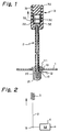
- FIG. 1 is a partly sectioned elevation showing an antenna embodying the present invention in an extended position;
- FIG. 2 is a schematic associated with FIG. 1;
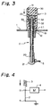
- FIG. 3 is a view similar to FIG. 1, showing the antenna in a retracted position;
- FIG. 4 is a schematic associated with FIG. 3;
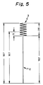
- FIG. 5 is a schematic showing specific dimensions of various portions included in the embodiment, as measured in the retracted position;
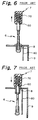
- FIG. 6 is a section showing a conventional antenna in an extended position;
- FIG. 7 is a view similar to FIG. 6, showing the antenna in a retracted position;
- FIG. 8 is a schematic of another conventional antenna in an extended position; and
- FIG. 9 is a view similar to FIG. 8, showing the antenna in a retracted position.
- To better understand the present invention, a brief reference will be made to a conventional small size antenna, shown in FIGS. 6 and 7. As shown, the antenna (referred to as a first antenna hereinafter) is mounted on the
casing 9 of a radio communication apparatus and made up of astraight antenna rod 6 and ashort antenna section 7 provided on the tip of therod 6. Theantenna rod 6 has an electrical length which is substantially one-quarter of the resonance wavelength. Theshort antenna section 7 has an electrical length of substantially one-quarter of the resonance wavelength. A loading coil, or antenna coil, 70 is disposed in theantenna section 7 and has a predetermined number of turns. As shown in FIG. 6, when theantenna rod 6 is extended from thecasing 9, theantenna rod 6 andloading coil 70 constitute a substantially half wavelength antenna in combination. As shown in FIG. 7, when theantenna rod 6 is retracted into thecasing 9, only theshort antenna section 7 with thecoil 70 is positioned externally of thecasing 9 and serves as a quarter wavelength antenna. There are also shown in the figures acircuit board 80, and afeed portion 8. - FIGS. 8 and 9 show another conventional small size antenna (referred to as a second antenna hereinafter). The same or similar constituent parts of this antenna as or to the constituents of the antenna described above are designated by the same reference numerals, and a detailed description thereof will not be made in order to avoid redundancy. As shown, the
antenna rod 6 and the antenna coil, or coiled element, 70 each having a quarter wavelength are physically separate from each other. As shown in FIG. 8, when theantenna rod 6 is extended from thecasing 9, the antenna is fed at the lower end of theantenna rod 6 with the result that substantially only theantenna rod 6 plays the role of an antenna. As shown in FIG. 9, when theantenna rod 6 is retracted into thecasing 9, it is disconnected from thefeed portion 8 while, at the same time, the lower end of thecoil 70 is brought into connection with thefeed portion 8. In this condition, only thecoil 70 serves as a short antenna. In the figures, thereference numeral 4 designates a matching circuit. - Regarding the structure, the first and second antennas described above are simpler than traditional small size antennas. However, the electric characteristic available with the first antenna is not desirable when the quarter
wavelength antenna rod 6 is extended from thecasing 9. Another problem with the first antenna is that gain is low since thecoil 70 degrades the electric performance of theantenna rod 6. It is extremely difficult to eliminate this problem. In the second antenna, thecoil 70 is spaced apart a predetermined distance from the tip of theantenna rod 6. The second antenna, therefore, needs an extra space for accommodation in thecasing 9. Moreover, both of the first and second antennas have a drawback that the total length of theantenna rod 6 andcoil 70 is constant and cannot be reduced, as needed. - Referring to FIGS. 1-5, an antenna embodying the present invention will be described. The illustrative embodiment pertains to a portable hand-held telephone using a 900 MHz frequency band. As shown, the antenna has a half wavelength whip antenna 2 (e.g. 167 mm as shown in FIG. 5) and a quarter wavelength short whip antenna 3 (e.g. 25 mm as shown in FIG. 5) provided on the tip of the
whip antenna 2. Thewhip antenna 3 is coaxial with and slidable relative to thewhip antenna 2. A loading coil orcoil element 31 is accommodated in thewhip antenna 3 and has a predetermined number of turns. Thewhip antenna 3 is enclosed within acase 30 made of resin. Abore 33 is formed in thecase 30 internally of thecoil 31. An upper and a lowerannular projection 32 are formed on the wall of thecase 30 defining thebore 33. A hole is formed through the bottom of thecase 30 for receiving the upper end of thewhip antenna 2. - The
whip antenna 2 is a flexible rod made of synthetic resin and having a flexible antenna core thereinside. Amovable connector 20 is fitted on the lower end of thewhip antenna 2 and held in conduction with the antenna core. Themovable connector 20 is made of brass.Stops whip antenna 2. Theupper stop 22 is received in thebore 33 via the hole of thecase 30. Thelower stop 21 is received in thecasing 1 of the telephone and slidable deeper into thecasing 1 away from the top wall of thecasing 1 which is formed with an opening. A cylindrical O-ring 10 is fitted in the opening of the top wall of thecasing 1. Afeed portion 12 extending from a circuit board, not shown, is connected to the O-ring 10. A hollow cylindricalfixed connector 11 is fitted in the O-ring 10. As shown in FIG. 1, when thewhip antenna 2 is extended from thecasing 1, thelower stop 21 abuts against the fixedconnector 11. In this condition, themovable connector 20 is electrically connected to thefeed portion 12 via the fixedconnector 11 and O-ring 10. In FIG. 1, thereference numeral 13 designates a feed point. - Specifically, assume that the user of the telephone has held the
case 3 and pulled thewhip antenna 3 out of thecasing 1. Then, theupper stop 22 is brought to below the lowerannular projection 32. Hence, the lower end of thecoil 31 is spaced apart from the tip of thewhip antenna 2 and, therefore, separated from the latter physically and electrically. At the same time, thewhip antenna 2 is fed from thefeed point 13 at the lower end thereof. In this condition, substantially only thewhip antenna 2 works as an antenna having a desirable electric characteristic without being effected by thecoil 31. More specifically, as shown in FIG. 2, theshort whip antenna 3 is, in effect, practically absent: only thewhip antenna 2 is connected to amatching circuit 4 via thefeed point 13. Although the total length of thewhip antennas whip antenna 2 is in the extended position. - As shown in FIG. 3, when the user presses the
case 30 of thewhip antenna 3 downward, thewhip antenna 2 begins to retract into thecasing 1. At this instant, theupper stop 22 moves to the upper end of thebore 33 over the lower and upperannular projections 32. This causes the lower end of thecoil 31 to overlap with the upper end of thewhip antenna 2 and, therefore, couples thecoil 31 andantenna 2 mechanically and electrically. Thewhip antenna 2 is fully received in thecasing 1 while having the upper end thereof positioned internally of the fixedconnector 11. Consequently, thecoil 31 is fed by capacity coupling. In this condition, the telephone awaits an incoming call with substantially only thecoil 31 working as an antenna. As FIG. 5 shows in a schematic, thewhip antenna 2 is, in effect, practically absent; only theshort whip antenna 3 is coupled to thefeed point 13 by capacity coupling. In this case, the total length of thewhip antennas individual antennas casing 1. This will be clearly understood with reference to specific dimensions shown in FIG. 5. - In the illustrative embodiment, when the
whip antenna 2 is in the retracted position, themovable connector 20 carried thereon is held in contact with ametallic ground member 5 which is located in a predetermined lower portion in thecasing 1. Connecting themovable connector 20 to ground is successful in making the impedance Z of thewhip antenna 2 infinite and, therefore, in fully shutting off the feed to theantenna 2. - Regarding the
upper stop 22 received in thewhip antenna 3 andannular projections 32, when thewhip antenna 2 is extended or retracted, they will allow the user to see if thewhip antenna 3 is settled at the expected position or not by a tactual sense. - If desired, the whip antenna or
antenna rod 2 may be provided with a telescopic configuration. Both thewhip antenna 2 and thecoil 31 may be of any desired wavelength capable of implementing transmission and reception, e.g., quarter or half wavelength. Further, the slidable configuration of thewhip antenna 2 andcoil 31 may be implemented by a bellows or a conventional arrangement for a rod antenna. - In summary, in accordance with the present invention, an antenna has an antenna coil having a predetermined number of turns and and provided on the upper end of a straight antenna rod. The coil is coaxial with and slidable relative to the antenna rod. When the coil is pulled upward, the lower end of the coil is moved away from the upper end of the antenna rod and, therefore, separated from the latter mechanically and electrically. Specifically, when the antenna rod is extended, the coil is moved away from the tip of the rod while the rod is fed at the lower end thereof. As a result, substantially only the antenna rod works as an antenna having a desirable electric characteristic without being effected by the coil. This is also true when the antenna rod is implemented as a telescopic rod antenna. On the other hand, when the antenna rod is pushed downward, the tip of the rod moves into the coil via the lower end of the coil. Consequently, the antenna rod and coil are coupled mechanically and electrically. Specifically, the total length of the antenna rod and coil is further reduced. In this condition, the coil overlaps with the tip of the antenna rod and is fed by capacity coupling via a feed point adjoining the tip of the rod. In this condition, substantially only the coil works as an antenna. The antenna, therefore, exhibits a desirable electric characteristic when pulled out of the casing of a radio communication apparatus and, in addition, promotes the efficient use of the limited space available in the casing.
- Various modifications will become possible for those skilled in the art after receiving the teachings of the present disclosure without departing from the scope thereof.
Claims (4)
- An antenna for a radio communication apparatus, comprising:
a first whip antenna having a first portion retractable into a casing of said apparatus and a second portion constantly positioned externally of said casing; and
a second whip antenna having a coil element in the form of a loading coil having a predetermined number of turns, said second whip antenna being coaxially provided on an upper end of said first whip antenna and slidable relative to and in an axial direction of said first whip antenna such that said second portion of said first whip antenna is movable between a position where one end of said coil element is disengaged from one end of said second portion and a position where said one end of said coil element is engaged with said one end of said second portion. - An antenna as claimed in claim 1, wherein said coil element of said first whip antenna is disposed in a case made of synthetic resin, said case having a bore coaxial with said loading coil.
- An antenna as claimed in claim 1 or 2, wherein said second portion of said first whip antenna has a grater diameter than said first portion and is slidably received in said bore of said case.
- An antenna as claimed in any of claims 1 to 3, wherein said first whip antenna has a telescopic rod antenna structure.
Applications Claiming Priority (2)
| Application Number | Priority Date | Filing Date | Title |
|---|---|---|---|
| JP37689/93 | 1993-02-26 | ||
| JP5037689A JP2520557B2 (en) | 1993-02-26 | 1993-02-26 | Radio antenna |
Publications (2)
| Publication Number | Publication Date |
|---|---|
| EP0613207A1 true EP0613207A1 (en) | 1994-08-31 |
| EP0613207B1 EP0613207B1 (en) | 1998-04-29 |
Family
ID=12504543
Family Applications (1)
| Application Number | Title | Priority Date | Filing Date |
|---|---|---|---|
| EP94102812A Expired - Lifetime EP0613207B1 (en) | 1993-02-26 | 1994-02-24 | Antenna for a radio communication apparatus |
Country Status (6)
| Country | Link |
|---|---|
| US (1) | US5438339A (en) |
| EP (1) | EP0613207B1 (en) |
| JP (1) | JP2520557B2 (en) |
| AU (1) | AU670482B2 (en) |
| CA (1) | CA2116475C (en) |
| DE (1) | DE69409855T2 (en) |
Cited By (19)
| Publication number | Priority date | Publication date | Assignee | Title |
|---|---|---|---|---|
| GB2296603A (en) * | 1994-12-23 | 1996-07-03 | Nokia Mobile Phones Ltd | Retractable antenna |
| EP0734092A1 (en) * | 1995-03-22 | 1996-09-25 | Ace Antenna Corporation | Inductive coupled extendable antenna |
| EP0736925A2 (en) * | 1995-04-07 | 1996-10-09 | Nokia Mobile Phones Ltd. | A double-acting antenna and a mobile phone comprising such an antenna |
| FR2739498A1 (en) * | 1995-09-29 | 1997-04-04 | Motorola Inc | ANTENNA ASSEMBLY FOR WIRELESS COMMUNICATION DEVICE |
| EP0772255A1 (en) * | 1995-10-31 | 1997-05-07 | Tokin Corporation | Multiband antenna with a distributed-constant dielectric resonant circuit, and multiband portable radio apparatus comprising such an antenna |
| GB2282705B (en) * | 1993-09-09 | 1997-10-15 | Mitsubishi Electric Corp | Antenna system having plural antenna portions |
| EP0825668A2 (en) * | 1996-08-22 | 1998-02-25 | Murata Manufacturing Co., Ltd. | Antenna and resonant-frequency-adjustment method therefor |
| WO1998043312A1 (en) * | 1997-03-24 | 1998-10-01 | Telefonaktiebolaget Lm Ericsson | Retractable antenna with shifting electrical length |
| WO1998049740A1 (en) * | 1997-04-29 | 1998-11-05 | Ericsson, Inc. | Radiotelephones with integrated matching antenna systems |
| US6008765A (en) * | 1994-12-23 | 1999-12-28 | Nokia Mobile Phones Limited | Retractable top load antenna |
| WO2000003454A1 (en) * | 1998-07-08 | 2000-01-20 | Ericsson, Inc. | Retractable dual-band tapped helical radiotelephone antennas |
| EP0996190A1 (en) * | 1998-04-28 | 2000-04-26 | Matsushita Electric Industrial Co., Ltd. | Antenna device for mobile radio communication |
| US6232924B1 (en) | 1998-12-21 | 2001-05-15 | Ericsson Inc. | Flat blade antenna and flip mounting structures |
| US6249688B1 (en) | 1998-12-21 | 2001-06-19 | Ericcson Inc. | Antenna electrical coupling configurations |
| US6301489B1 (en) | 1998-12-21 | 2001-10-09 | Ericsson Inc. | Flat blade antenna and flip engagement and hinge configurations |
| CN1073295C (en) * | 1995-09-22 | 2001-10-17 | 三菱电机株式会社 | Antenna device |
| CN1094664C (en) * | 1995-02-07 | 2002-11-20 | 索尼公司 | Antenna for two frequency bands |
| WO2003019719A1 (en) * | 2001-08-27 | 2003-03-06 | Qualcomm Incorporated | Selectively coupled two-piece antenna |
| EP1353400A2 (en) | 1996-09-11 | 2003-10-15 | Matsushita Electric Industrial Co., Ltd. | Antenna system |
Families Citing this family (22)
| Publication number | Priority date | Publication date | Assignee | Title |
|---|---|---|---|---|
| BR9405603A (en) * | 1993-09-20 | 1999-09-08 | Motorola Inc | Installation of antenna adapted for wireless communication device |
| MY113389A (en) * | 1994-06-28 | 2002-02-28 | Sony Corp | Antenna assembly and portable radio apparatus |
| US5504494A (en) * | 1994-11-25 | 1996-04-02 | Motorola, Inc. | Multi-stage antenna |
| JP2944444B2 (en) * | 1995-01-12 | 1999-09-06 | 日本電気株式会社 | Portable radio |
| KR960030478A (en) * | 1995-01-27 | 1996-08-17 | 김광호 | Antenna of wireless device |
| KR100194422B1 (en) * | 1995-04-27 | 1999-06-15 | 김광호 | Antenna connection device of portable wireless device |
| DE69522668T2 (en) * | 1995-05-17 | 2002-06-20 | Murata Manufacturing Co | Surface mount antenna system |
| JP2723836B2 (en) * | 1995-06-16 | 1998-03-09 | 埼玉日本電気株式会社 | Radio antenna |
| GB2308013B (en) * | 1995-12-07 | 1999-05-12 | Nokia Mobile Phones Ltd | A radio device |
| US5739792A (en) * | 1995-12-22 | 1998-04-14 | Motorola, Inc. | Wireless communication device with electrical contacts |
| US5963871A (en) * | 1996-10-04 | 1999-10-05 | Telefonaktiebolaget Lm Ericsson | Retractable multi-band antennas |
| EP0986834A1 (en) * | 1997-06-03 | 2000-03-22 | Galtronics Ltd. | Retractable antenna |
| US6163300A (en) * | 1997-08-07 | 2000-12-19 | Tokin Corporation | Multi-band antenna suitable for use in a mobile radio device |
| US5943027A (en) * | 1997-10-03 | 1999-08-24 | Motorola, Inc. | Telescopic antenna assembly |
| US6329962B2 (en) | 1998-08-04 | 2001-12-11 | Telefonaktiebolaget Lm Ericsson (Publ) | Multiple band, multiple branch antenna for mobile phone |
| US6222505B1 (en) | 1997-12-03 | 2001-04-24 | Mitsubishi Denki Kabushiki Kaisha | Composite antenna apparatus |
| US6005523A (en) * | 1997-12-11 | 1999-12-21 | Ericsson Inc. | Antenna rod disconnect mechanisms and associated methods |
| US5969684A (en) * | 1998-05-13 | 1999-10-19 | Ace Technology Co., Ltd. | Capacitive coupled extendable antenna for portable communication devices |
| US6353443B1 (en) | 1998-07-09 | 2002-03-05 | Telefonaktiebolaget Lm Ericsson (Publ) | Miniature printed spiral antenna for mobile terminals |
| US6166694A (en) * | 1998-07-09 | 2000-12-26 | Telefonaktiebolaget Lm Ericsson (Publ) | Printed twin spiral dual band antenna |
| US6343208B1 (en) | 1998-12-16 | 2002-01-29 | Telefonaktiebolaget Lm Ericsson (Publ) | Printed multi-band patch antenna |
| US6281851B1 (en) | 2000-01-21 | 2001-08-28 | Motorola, Inc. | Antenna assembly and communication device utilizing such antenna assembly |
Citations (4)
| Publication number | Priority date | Publication date | Assignee | Title |
|---|---|---|---|---|
| US4121218A (en) * | 1977-08-03 | 1978-10-17 | Motorola, Inc. | Adjustable antenna arrangement for a portable radio |
| EP0372720A1 (en) * | 1988-11-08 | 1990-06-13 | Kabushiki Kaisha Toshiba | Extendable antenna device |
| WO1992016980A1 (en) * | 1991-03-19 | 1992-10-01 | Dancall Radio A/S | An antenna construction with an extensible antenna element |
| US5168278A (en) * | 1991-03-19 | 1992-12-01 | Sanyo Electric Co., Ltd. | Antenna device for electronic devices |
Family Cites Families (8)
| Publication number | Priority date | Publication date | Assignee | Title |
|---|---|---|---|---|
| US4868576A (en) * | 1988-11-02 | 1989-09-19 | Motorola, Inc. | Extendable antenna for portable cellular telephones with ground radiator |
| US5204687A (en) * | 1990-07-19 | 1993-04-20 | Galtronics Ltd. | Electrical device and electrical transmitter-receiver particularly useful in a ct2 cordless telephone |
| GB9105586D0 (en) * | 1991-03-16 | 1991-05-01 | Antenna Products Ltd | Radio antennas |
| JPH04318701A (en) * | 1991-04-18 | 1992-11-10 | Fujitsu Ltd | Antenna mount structure for mobile radio communication equipment |
| JP2575549B2 (en) * | 1991-05-07 | 1997-01-29 | 富士通株式会社 | Antenna mounting structure for wireless terminal device |
| GB2257835B (en) * | 1991-07-13 | 1995-10-11 | Technophone Ltd | Retractable antenna |
| US5204681A (en) * | 1991-09-24 | 1993-04-20 | Gordian Holding Corporation | Radio frequency automatic identification system |
| SE501551C2 (en) * | 1992-10-29 | 1995-03-13 | Allgon Ab | Antenna device for portable equipment |
-
1993
- 1993-02-26 JP JP5037689A patent/JP2520557B2/en not_active Expired - Fee Related
-
1994
- 1994-02-24 DE DE69409855T patent/DE69409855T2/en not_active Expired - Fee Related
- 1994-02-24 EP EP94102812A patent/EP0613207B1/en not_active Expired - Lifetime
- 1994-02-24 US US08/201,338 patent/US5438339A/en not_active Expired - Lifetime
- 1994-02-25 AU AU56415/94A patent/AU670482B2/en not_active Ceased
- 1994-02-25 CA CA002116475A patent/CA2116475C/en not_active Expired - Fee Related
Patent Citations (4)
| Publication number | Priority date | Publication date | Assignee | Title |
|---|---|---|---|---|
| US4121218A (en) * | 1977-08-03 | 1978-10-17 | Motorola, Inc. | Adjustable antenna arrangement for a portable radio |
| EP0372720A1 (en) * | 1988-11-08 | 1990-06-13 | Kabushiki Kaisha Toshiba | Extendable antenna device |
| WO1992016980A1 (en) * | 1991-03-19 | 1992-10-01 | Dancall Radio A/S | An antenna construction with an extensible antenna element |
| US5168278A (en) * | 1991-03-19 | 1992-12-01 | Sanyo Electric Co., Ltd. | Antenna device for electronic devices |
Non-Patent Citations (1)
| Title |
|---|
| J. T. WIGGENHORN: "HEL/TEL Antenna", MOTOROLA TECHNICAL DEVELOPMENTS, vol. 19, June 1993 (1993-06-01), SCHAUMBURG ILLINOIS US, pages 118 * |
Cited By (30)
| Publication number | Priority date | Publication date | Assignee | Title |
|---|---|---|---|---|
| GB2282705B (en) * | 1993-09-09 | 1997-10-15 | Mitsubishi Electric Corp | Antenna system having plural antenna portions |
| GB2296603B (en) * | 1994-12-23 | 1999-02-17 | Nokia Mobile Phones Ltd | Retractable top load antenna |
| GB2296603A (en) * | 1994-12-23 | 1996-07-03 | Nokia Mobile Phones Ltd | Retractable antenna |
| US6008765A (en) * | 1994-12-23 | 1999-12-28 | Nokia Mobile Phones Limited | Retractable top load antenna |
| CN1094664C (en) * | 1995-02-07 | 2002-11-20 | 索尼公司 | Antenna for two frequency bands |
| EP0734092A1 (en) * | 1995-03-22 | 1996-09-25 | Ace Antenna Corporation | Inductive coupled extendable antenna |
| EP0736925A2 (en) * | 1995-04-07 | 1996-10-09 | Nokia Mobile Phones Ltd. | A double-acting antenna and a mobile phone comprising such an antenna |
| EP0736925A3 (en) * | 1995-04-07 | 1997-11-05 | Nokia Mobile Phones Ltd. | A double-acting antenna and a mobile phone comprising such an antenna |
| CN1073295C (en) * | 1995-09-22 | 2001-10-17 | 三菱电机株式会社 | Antenna device |
| FR2739498A1 (en) * | 1995-09-29 | 1997-04-04 | Motorola Inc | ANTENNA ASSEMBLY FOR WIRELESS COMMUNICATION DEVICE |
| US5812093A (en) * | 1995-09-29 | 1998-09-22 | Motorola, Inc. | Antenna assembly for a wireless-communication device |
| US6011516A (en) * | 1995-10-31 | 2000-01-04 | Tokin Corporation | Multiband antenna with a distributed-constant dielectric resonant circuit as an LC parallel resonant circuit, and multiband portable radio apparatus using the multiband antenna |
| EP0772255A1 (en) * | 1995-10-31 | 1997-05-07 | Tokin Corporation | Multiband antenna with a distributed-constant dielectric resonant circuit, and multiband portable radio apparatus comprising such an antenna |
| EP0825668A2 (en) * | 1996-08-22 | 1998-02-25 | Murata Manufacturing Co., Ltd. | Antenna and resonant-frequency-adjustment method therefor |
| EP0825668B1 (en) * | 1996-08-22 | 2005-12-07 | Murata Manufacturing Co., Ltd. | Antenna |
| EP1353400A2 (en) | 1996-09-11 | 2003-10-15 | Matsushita Electric Industrial Co., Ltd. | Antenna system |
| EP1353400A3 (en) * | 1996-09-11 | 2003-11-19 | Matsushita Electric Industrial Co., Ltd. | Antenna system |
| WO1998043312A1 (en) * | 1997-03-24 | 1998-10-01 | Telefonaktiebolaget Lm Ericsson | Retractable antenna with shifting electrical length |
| US5999133A (en) * | 1997-03-24 | 1999-12-07 | Telefonaktiebolaget Lm Ericsson | Retractable antenna with shifting electrical length |
| US6016431A (en) * | 1997-04-29 | 2000-01-18 | Ericsson Inc. | Radiotelephones with integrated matching antenna systems |
| WO1998049740A1 (en) * | 1997-04-29 | 1998-11-05 | Ericsson, Inc. | Radiotelephones with integrated matching antenna systems |
| EP0996190A1 (en) * | 1998-04-28 | 2000-04-26 | Matsushita Electric Industrial Co., Ltd. | Antenna device for mobile radio communication |
| EP0996190A4 (en) * | 1998-04-28 | 2004-12-29 | Matsushita Electric Ind Co Ltd | Antenna device for mobile radio communication |
| WO2000003454A1 (en) * | 1998-07-08 | 2000-01-20 | Ericsson, Inc. | Retractable dual-band tapped helical radiotelephone antennas |
| US6336036B1 (en) | 1998-07-08 | 2002-01-01 | Ericsson Inc. | Retractable dual-band tapped helical radiotelephone antennas |
| US6301489B1 (en) | 1998-12-21 | 2001-10-09 | Ericsson Inc. | Flat blade antenna and flip engagement and hinge configurations |
| US6249688B1 (en) | 1998-12-21 | 2001-06-19 | Ericcson Inc. | Antenna electrical coupling configurations |
| US6232924B1 (en) | 1998-12-21 | 2001-05-15 | Ericsson Inc. | Flat blade antenna and flip mounting structures |
| WO2003019719A1 (en) * | 2001-08-27 | 2003-03-06 | Qualcomm Incorporated | Selectively coupled two-piece antenna |
| CN100350673C (en) * | 2001-08-27 | 2007-11-21 | 高通股份有限公司 | Selectively coupled two-piece antenna |
Also Published As
| Publication number | Publication date |
|---|---|
| CA2116475C (en) | 1997-05-27 |
| CA2116475A1 (en) | 1994-08-27 |
| DE69409855D1 (en) | 1998-06-04 |
| DE69409855T2 (en) | 1998-11-26 |
| EP0613207B1 (en) | 1998-04-29 |
| AU670482B2 (en) | 1996-07-18 |
| JP2520557B2 (en) | 1996-07-31 |
| AU5641594A (en) | 1994-09-01 |
| US5438339A (en) | 1995-08-01 |
| JPH06252620A (en) | 1994-09-09 |
Similar Documents
| Publication | Publication Date | Title |
|---|---|---|
| US5438339A (en) | Antenna for a radio communication apparatus | |
| EP0613206B1 (en) | Antenna for a radio communication apparatus | |
| JP3406328B2 (en) | Retractable antenna | |
| US6198440B1 (en) | Dual band antenna for radio terminal | |
| KR100232981B1 (en) | Antenna for two frequency bands | |
| KR100299299B1 (en) | Antenna device for mobile communication equipment | |
| EP0734092B1 (en) | Inductive coupled extendable antenna | |
| JPH0770896B2 (en) | Extendable antenna system and portable radio using the same | |
| US5612704A (en) | Retractable antenna | |
| US5243355A (en) | Semiautomatic retractable antenna apparatus | |
| US5717409A (en) | Dual frequency band antenna system | |
| US5691730A (en) | Retractable broad-band antenna for portable telephones | |
| JPH03245603A (en) | Antenna | |
| JPH11355029A (en) | Antenna system | |
| GB2257837A (en) | Retractable antenna | |
| US6239768B1 (en) | Dual band retractable antenna system with capacitive coupling | |
| US6097341A (en) | Structure of an antenna for a portable radio communication apparatus | |
| EP0961343A2 (en) | Telescopic antenna assembly for portable phone | |
| US6359592B1 (en) | Minimum frequency shift telescoping antenna | |
| US5136302A (en) | Antenna for a portable transceiver | |
| US5030966A (en) | Antenna for a portable transceiver | |
| JPH066121A (en) | Antenna system | |
| JP3595519B2 (en) | Antenna device | |
| JP2501413B2 (en) | Antenna and radio | |
| US20050007282A1 (en) | Antenna |
Legal Events
| Date | Code | Title | Description |
|---|---|---|---|
| PUAI | Public reference made under article 153(3) epc to a published international application that has entered the european phase |
Free format text: ORIGINAL CODE: 0009012 |
|
| AK | Designated contracting states |
Kind code of ref document: A1 Designated state(s): DE FR GB IT SE |
|
| 17P | Request for examination filed |
Effective date: 19940713 |
|
| 17Q | First examination report despatched |
Effective date: 19960513 |
|
| GRAG | Despatch of communication of intention to grant |
Free format text: ORIGINAL CODE: EPIDOS AGRA |
|
| GRAG | Despatch of communication of intention to grant |
Free format text: ORIGINAL CODE: EPIDOS AGRA |
|
| GRAG | Despatch of communication of intention to grant |
Free format text: ORIGINAL CODE: EPIDOS AGRA |
|
| GRAH | Despatch of communication of intention to grant a patent |
Free format text: ORIGINAL CODE: EPIDOS IGRA |
|
| GRAH | Despatch of communication of intention to grant a patent |
Free format text: ORIGINAL CODE: EPIDOS IGRA |
|
| GRAA | (expected) grant |
Free format text: ORIGINAL CODE: 0009210 |
|
| AK | Designated contracting states |
Kind code of ref document: B1 Designated state(s): DE FR GB IT SE |
|
| REF | Corresponds to: |
Ref document number: 69409855 Country of ref document: DE Date of ref document: 19980604 |
|
| ITF | It: translation for a ep patent filed |
Owner name: MODIANO & ASSOCIATI S.R.L. |
|
| ET | Fr: translation filed | ||
| PLBE | No opposition filed within time limit |
Free format text: ORIGINAL CODE: 0009261 |
|
| STAA | Information on the status of an ep patent application or granted ep patent |
Free format text: STATUS: NO OPPOSITION FILED WITHIN TIME LIMIT |
|
| 26N | No opposition filed | ||
| PGFP | Annual fee paid to national office [announced via postgrant information from national office to epo] |
Ref country code: SE Payment date: 20010205 Year of fee payment: 8 |
|
| PGFP | Annual fee paid to national office [announced via postgrant information from national office to epo] |
Ref country code: FR Payment date: 20010213 Year of fee payment: 8 |
|
| PGFP | Annual fee paid to national office [announced via postgrant information from national office to epo] |
Ref country code: DE Payment date: 20010221 Year of fee payment: 8 |
|
| REG | Reference to a national code |
Ref country code: GB Ref legal event code: IF02 |
|
| PG25 | Lapsed in a contracting state [announced via postgrant information from national office to epo] |
Ref country code: SE Free format text: LAPSE BECAUSE OF NON-PAYMENT OF DUE FEES Effective date: 20020225 |
|
| PG25 | Lapsed in a contracting state [announced via postgrant information from national office to epo] |
Ref country code: DE Free format text: LAPSE BECAUSE OF NON-PAYMENT OF DUE FEES Effective date: 20020903 |
|
| EUG | Se: european patent has lapsed |
Ref document number: 94102812.8 |
|
| PG25 | Lapsed in a contracting state [announced via postgrant information from national office to epo] |
Ref country code: FR Free format text: LAPSE BECAUSE OF NON-PAYMENT OF DUE FEES Effective date: 20021031 |
|
| REG | Reference to a national code |
Ref country code: FR Ref legal event code: ST |
|
| PG25 | Lapsed in a contracting state [announced via postgrant information from national office to epo] |
Ref country code: IT Free format text: LAPSE BECAUSE OF NON-PAYMENT OF DUE FEES;WARNING: LAPSES OF ITALIAN PATENTS WITH EFFECTIVE DATE BEFORE 2007 MAY HAVE OCCURRED AT ANY TIME BEFORE 2007. THE CORRECT EFFECTIVE DATE MAY BE DIFFERENT FROM THE ONE RECORDED. Effective date: 20050224 |
|
| PGFP | Annual fee paid to national office [announced via postgrant information from national office to epo] |
Ref country code: GB Payment date: 20100202 Year of fee payment: 17 |
|
| GBPC | Gb: european patent ceased through non-payment of renewal fee |
Effective date: 20110224 |
|
| PG25 | Lapsed in a contracting state [announced via postgrant information from national office to epo] |
Ref country code: GB Free format text: LAPSE BECAUSE OF NON-PAYMENT OF DUE FEES Effective date: 20110224 |