EP0613762A1 - Surgical manipulator - Google Patents
Surgical manipulator Download PDFInfo
- Publication number
- EP0613762A1 EP0613762A1 EP94200424A EP94200424A EP0613762A1 EP 0613762 A1 EP0613762 A1 EP 0613762A1 EP 94200424 A EP94200424 A EP 94200424A EP 94200424 A EP94200424 A EP 94200424A EP 0613762 A1 EP0613762 A1 EP 0613762A1
- Authority
- EP
- European Patent Office
- Prior art keywords
- hand
- distal
- wires
- human
- movement
- Prior art date
- Legal status (The legal status is an assumption and is not a legal conclusion. Google has not performed a legal analysis and makes no representation as to the accuracy of the status listed.)
- Withdrawn
Links
Images


Classifications
-
- B—PERFORMING OPERATIONS; TRANSPORTING
- B25—HAND TOOLS; PORTABLE POWER-DRIVEN TOOLS; MANIPULATORS
- B25J—MANIPULATORS; CHAMBERS PROVIDED WITH MANIPULATION DEVICES
- B25J15/00—Gripping heads and other end effectors
- B25J15/0009—Gripping heads and other end effectors comprising multi-articulated fingers, e.g. resembling a human hand
-
- A—HUMAN NECESSITIES
- A61—MEDICAL OR VETERINARY SCIENCE; HYGIENE
- A61B—DIAGNOSIS; SURGERY; IDENTIFICATION
- A61B34/00—Computer-aided surgery; Manipulators or robots specially adapted for use in surgery
- A61B34/70—Manipulators specially adapted for use in surgery
-
- A—HUMAN NECESSITIES
- A61—MEDICAL OR VETERINARY SCIENCE; HYGIENE
- A61B—DIAGNOSIS; SURGERY; IDENTIFICATION
- A61B34/00—Computer-aided surgery; Manipulators or robots specially adapted for use in surgery
- A61B34/70—Manipulators specially adapted for use in surgery
- A61B34/74—Manipulators with manual electric input means
-
- B—PERFORMING OPERATIONS; TRANSPORTING
- B25—HAND TOOLS; PORTABLE POWER-DRIVEN TOOLS; MANIPULATORS
- B25J—MANIPULATORS; CHAMBERS PROVIDED WITH MANIPULATION DEVICES
- B25J13/00—Controls for manipulators
- B25J13/02—Hand grip control means
-
- B—PERFORMING OPERATIONS; TRANSPORTING
- B25—HAND TOOLS; PORTABLE POWER-DRIVEN TOOLS; MANIPULATORS
- B25J—MANIPULATORS; CHAMBERS PROVIDED WITH MANIPULATION DEVICES
- B25J3/00—Manipulators of master-slave type, i.e. both controlling unit and controlled unit perform corresponding spatial movements
-
- B—PERFORMING OPERATIONS; TRANSPORTING
- B25—HAND TOOLS; PORTABLE POWER-DRIVEN TOOLS; MANIPULATORS
- B25J—MANIPULATORS; CHAMBERS PROVIDED WITH MANIPULATION DEVICES
- B25J9/00—Programme-controlled manipulators
- B25J9/10—Programme-controlled manipulators characterised by positioning means for manipulator elements
- B25J9/104—Programme-controlled manipulators characterised by positioning means for manipulator elements with cables, chains or ribbons
-
- A—HUMAN NECESSITIES
- A61—MEDICAL OR VETERINARY SCIENCE; HYGIENE
- A61B—DIAGNOSIS; SURGERY; IDENTIFICATION
- A61B17/00—Surgical instruments, devices or methods, e.g. tourniquets
- A61B17/00234—Surgical instruments, devices or methods, e.g. tourniquets for minimally invasive surgery
-
- A—HUMAN NECESSITIES
- A61—MEDICAL OR VETERINARY SCIENCE; HYGIENE
- A61B—DIAGNOSIS; SURGERY; IDENTIFICATION
- A61B17/00—Surgical instruments, devices or methods, e.g. tourniquets
- A61B17/28—Surgical forceps
- A61B17/29—Forceps for use in minimally invasive surgery
- A61B17/2909—Handles
-
- A—HUMAN NECESSITIES
- A61—MEDICAL OR VETERINARY SCIENCE; HYGIENE
- A61B—DIAGNOSIS; SURGERY; IDENTIFICATION
- A61B34/00—Computer-aided surgery; Manipulators or robots specially adapted for use in surgery
- A61B34/70—Manipulators specially adapted for use in surgery
- A61B34/74—Manipulators with manual electric input means
- A61B2034/741—Glove like input devices, e.g. "data gloves"
Definitions
- the invention relates to a mechanical manipulator for working in inaccessible areas and cavities according to the preamble of claim 1.
- PS-US-4,302,138 and PS-F-78 02714 show a device which either directly controls the movement of the human hand measuring on the hand or by hand via mechanical linkages on electrical sensors located further away. These pass on the electrical signal to control a gripper.
- US Pat. No. 4,834,761 shows a device which is operated by means of a system of hydraulically operating pistons and whose movement is transmitted to the fingers by means of hoops (pulley structures).
- US Pat. No. 5,092,646 shows a device operated by servomotors, in which a whole finger of one hand is bent by means of stretchable bands over a double winch construction and stretched over a spiral spring.
- PS-US-4,986,723 the stretching movement is also carried out with the aid of a spiral spring and the bending movement is carried out with the aid of a pulley.
- PS-US-4,921,293 also shows moving fingers with pulley designs.
- control signals of the control panel are transmitted electrically to the gripper device in the named apparatus.
- a mechanical transmission is known in DE-AS-2048563.
- a permanently installed working arm is moved here using pulley blocks.
- the movement carried out by the device arm is not picked up and transmitted by the operator's arm, but by a control arm to be moved by this person. The operator must constantly consider how to steer the control arm in order to bring the working arm into the desired position.
- DE-PS-2939452 The same occurs in the idea set out in DE-PS-2939452. Again, it is not a portable device, but a fixed one. Both arms are directly rotatably connected to each other via an axis, so that the pivoting of the control arm leads to a corresponding pivoting of the slave arm. Because of this design, however, the device cannot be used for motion controls through a thin channel, such as that of a trocar. However, this is the aim of claim 1 of the invention presented here.
- the two parallelograms shown in the document DE-PS-2939452 are a direct part of the arms, without which no single movement can be carried out.
- the motion transmission of claim 1 is achieved by pushing or pulling wires or threads.
- the levers or pantographic devices of claim 2 only serve to correct the displacement of these wires or threads and are not a direct part of the links.
- the movement of the device members is also possible without these devices, so that only an adjustment of the Bowden cable movement takes place. This adjustment is e.g. important if a new smaller distal hand is to be placed on a proximal hand. Special movements can hereby be achieved in the manner specified below.
- All of these devices are for use in inaccessible areas of small dimensions - such as the abdominal cavity of the person - unsuitable due to its size and its complicated structure.
- the invention is therefore also based on the object of providing an easily miniaturized distal hand-arm device which is also easy to clean.
- the device shows an overall representation of a possible form of the device. It consists of the holder 1 for the human extremity forearm 2, hand body 3 and the five fingers 4, 5, 6, 7 and 8 with individual links.
- the holder 1 is designed here as a kind of rubber glove, which fits the human extremity with a precise fit and which moves easily and without obstructing.
- the apparatus consists of the distal extremity 9, which is made up of appropriate limbs, namely the forearm 10, hand body 11 and the five fingers 12, 13, 14, 15 and 16. According to their shape and function, these correspond to the human extremity.
- a rigid channel 17 'and 17' ' are the wires 18, which are movably attached to the links 20 of the rubber-like holder 1 with their proximal ends 19' and movably attached to the links 20 '' of the distal extremity with their distal ends 19 '' are.
- the direction and path length of the wires 18 moved by the human hand are adapted to the requirements of the distal extremity via a coupling element 21 described below.
- the distal hand can be folded in such a way that it can be pushed with the front part of the channel 17 ′′ through a trocar 24 onto or into the operating area.
- the movement of the upper arm against the forearm is not shown in this example.
- the Bowden cables can have different dimensions. It may be advisable to use thicker cables to transmit the movement of larger human limbs and thinner cables to transmit smaller ones. Different materials such as metals or plastics can also be used. For example, it makes sense to use plastics such as PTFE (Teflon®) or materials with a similarly low coefficient of friction in order to optimize the sliding of the cables in the sleeves.
- FIG. 1 A human finger 4 ° is shown with the finger end member 250, the finger middle member 26 °, the finger base member 27 ° and the corresponding middle hand part 280.
- the finger fits into the holder 29, which is not designed here as a rubber glove, which consists of corresponding members 25 ', 26', 27 'and 28' and 30 joints.
- the device finger 4 '' drawn too large for better illustration, with corresponding members 25 '', 26 '', 27 '' and 28 ''.
- the proximal end parts 31 'of the wires do not run freely over the palm of the hand here, but directly into the sheath 32 fastened to the neighboring link, with which they form a type of Bowden cable.
- the distal parts 31 ′′ of the wires run partly in the phalanges.
- the channel is assumed to be non-rigid, which is indicated by the curve-like course 35 ′′ of the wire in the distal part 34 ′′. For the sake of clarity, only one wire is shown.
- the corresponding members 25 'and 26' also bend around their joint 33 ', since the holder joins the finger movement without hindrance.
- the proximal transmission wire 34 ' is thereby pushed into a Bowden cable sheath 35'.
- the direction of movement of the wire is reversed by a lever 34 '' '.
- the finger end member 25 ′′ on the distal finger can now be bent against the finger middle member 26 ′′ about the common joint 33 ′′.
- the distance traveled by the proximal part 34 'of the wire can be determined using the cosine theorem with the sizes shown in partial image I of FIG. 1. These result from the distance b 'of the wire attachment to the pivot point 33', the distance a 'of the casing opening attached to the neighboring finger member from the pivot point and the diffraction angle ⁇ '. Corresponding sizes a ′′, b ′′ and ⁇ ′′ are shown in partial image II for the distal side.
- the angular transmission ratio ⁇ '' / ⁇ ' which will be equal to 1 for most applications, can be set via the distances a' ', b' ', a' and b 'and that of the coupling rod c' 'and c'.
- FIG. 3 represents the glove shown only with the aid of a finger, in the rubber material of which the Bowden cables are embedded.
- the wires 31 ' are then movably fastened, for example, to axes 72 or, with ball joints (not shown here), to articulated holders 73' embedded in the glove.
- the advantage of this type of holder is the precise fit for the human extremity and the smooth mobility.
- two threads 37 and 38 can also be used instead of the wires.
- the sleeves 39 and 40 belonging to the threads are attached above and below a phalange 41.
- the finger member 42 is bent around the joint 36 and vice versa.
- Corresponding parts for taking up the thread can then also be located on the corresponding proximal members of the device.
- Fig. 5 shows the recording of the rotational movement of the human hand 43 about the axis 44 of the forearm 45 by means of two Bowden cables.
- the sleeves 46 and 47 end on the arm part 48 of the holder and the cables 49 and 50 which intersect on the forearm 45 on the hand part of the holder. If the hand 43, viewed from the forearm 45, is now rotated counterclockwise in the direction of the arrow, the train 50 is pushed into its casing 47 and the other 49 is pulled out of its 46. Corresponding distal rotary movement can be achieved by reversely crossing wires between device forearm and hand can be reached.
- Claim 2 is based on the problem of transferring the different proportions of the human hand of the surgeon to that of the device hand.
- the problem can be caused on the one hand by the fact that the device hands have different dimensions.
- the problem can arise from the desire to make special hand movements appear different.
- the solution to this problem set out in claim 2 uses the technique of levers and rod constructions in the manner of a pantograph.
- FIG. 6a Another design for this is shown in FIG. 6a.
- Two Bowden cables 52 and 53 are connected to their sleeves 52a and 53a.
- the wires 52b and 53b are rotatable and - unlike the lever 34 '' 'of FIG. 2 - attached to the coupling rod 54 on the same side as the pivot point 55, so that no change in direction occurs here. If wire 52b is now pulled out of its sheath 52a, wire 53b is pushed into its sheath 53a.
- the ratio of the path change of the wire 52b to wire 53b results e.g. from the beam set with knowledge of the variably adjustable coupling rod taps n and m.
- Fig. 6b shows the nature of the pantographic mechanism in a clearer form. It is a transmission link with three coupling rods 56, 57 and 58 and a non-constant angular transmission ( ⁇ '' / ⁇ ' ⁇ constant, see drawing I and II of Fig. 2). This is exemplified by four movement stages s1, s2, s3 and s4 of the movement. In stages s1 and s2, wire 60 is also advanced by constantly pushing wire 59 forward. From stage s3, however, the direction of movement of the wire 60 then turns, although wire 59 is constantly advanced, stage 4. It is therefore possible to control specific movement sequences for special operations that would not be accessible to the human hand. For this purpose, the folding of the device hand 61 by an angle which is abnormal for the human hand is also shown in FIG. 6c.
- Claim 3 is to be explained with reference to the following and to FIG. 7.
- devices usually have to be designed so that they can be sterilized. Hold materials e.g. In the steam ovens (autoclaves) used for this purpose, the temperatures or the humidity do not rise or devices have to be disassembled so that all hidden cavities can also be cleaned and subsequently sterilized.
- steam ovens autoclaves
- this problem can be avoided by putting a rubber-elastic glove on this hand, similar to the human surgeon's hand. This can then be thrown away after the operation. The device hand itself then only needs to be disinfected.
- a rubber-elastic cover can also serve as a joint for particularly small distal extremities.
- Fig. 7a and -b shows this on two links 62 and 63. These are connected to a somewhat thicker rubber piece 64 glued to their underside. Said rubber-elastic covering 65 envelops both members 62 and 63 and others.
- the link 63 evades the pressure generated in that it bends against the link 62, holding onto the glued-on rubber piece 64, FIG. 7b.
- the tensioned rubber sleeve can then pull the link 63 back into its initial position by relaxing, FIG. 7a.
- Claim 4 is to be explained with reference to FIG. 8.
- the wires can be sheared sideways and thus a transmission error can occur.
- Fig. 8 a human finger 4 ° is now shown, the movement of the finger middle member 67 against the finger base member 68 is carried out by means of a joint 69 and a Bowden cable 71 lying on the finger.
- the wire 70 is encased in the free-running part with a spiral spring 74, which guides the wire safely in its sheath 75 without being broken out.
- the principle of a novel manipulator hand is shown in cross section in FIG. 8 with the aid of a finger 76.
- the finger 76 consists of a spiral spring 77, which is embedded in a bore 78 on the hand base 79.
- the spiral spring 77 is connected to a metal bolt 80 at the finger end.
- a rope 81 is fixedly connected to the metal bolt 80 and runs inside and along the spring 77 through a bore 82 of the hand part 79.
- the rope 81 is loose, in Fig. 8b it is pulled from the proximal end, see arrow . Due to the pulling, the spiral spring is curved, the finger bends.
- a rubber profile 83 which is shown in Fig. 8c.
- Ropes, for example 81 ', can be introduced via further bores 84, FIGS. 8a and b, to expand the curvature of the finger.
- FIG. 10 shows a finger in cross section, to which stability and a preferred curvature have been imparted by a thin sheet 84 inserted into the spiral spring 77. It preferably bends in the directions indicated by arrows.
- the pouring into a rubber 85 is shown in FIG. 11 with the aid of a finger.
- the inner profile 83 is replaced by this design and the finger cannot get stuck to foreign objects while working with the manipulator.
- the distal hand can be given an appearance that resembles a human hand, so that this suggestion gives the surgeon an important and known relationship to the environment for the success of his work.
- a manipulator is shown in side view and plan view in FIG. 12, the coupling member 88 of which is fastened on the surface of the proximal part 97.
- This part of the human hand hardly moves and therefore offers a good hold for the coupling member 88.
- the bridle cables 90 run on the proximal glove, as shown, or can be incorporated into the elastic material of the glove.
- the inner parts of the bouquet cables 89 again run freely, without a sheath.
- the Bowden cable of the thumb parts can also run in the palm of your hand.
- FIG. 13 shows a manipulator in which the coupling member 91 lies in the cavity of the proximal part.
- the human hand 92 grips the manipulator.
- the advantage here is the firmer and more stable construction of the manipulator. Because the plungers 93 and 94 absorbing the movement of the fingers can be built more solidly and can therefore be subjected to greater loads. With a manipulator of this type, you can access it more firmly.
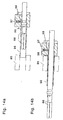
- FIG. 14 shows a protective device for the distal manipulator hand 86.
- the filigree distal finger structures can be damaged when the manipulator is pulled abruptly into the trocar sleeve.
- a snap device 97 with a protective cover 96 prevents this.
- the distal hand 86 lies completely in its protective sheath 96. This corresponds to the insertion of the manipulator into the trocar sleeve. If the device is then pressed with the pressure switch 98 onto the trocar 95, a locking pin 99 is pulled up in such a way that the manipulator is released from its protective cover 96 and can be freely pushed to the site of the operation, FIG. 14.b.
- the mechanism also works in the opposite direction.
- distal hand can be rotated around the transfer rod 100. This gives you more freedom of movement.
- a handle for the second hand of the surgeon, with which this rotational movement can be carried out, could be located on the transfer rod 100.
Abstract
Description
Die Erfindung betrifft einen mechanischen Manipulator zum Arbeiten in unzugänglichen Gebieten und Hohlräumen nach dem Oberbegriff des Anspruchs 1.The invention relates to a mechanical manipulator for working in inaccessible areas and cavities according to the preamble of
In der neueren endoskopisch arbeitenden Minimal Invasiven Chirurgie, aber auch in vielen Bereichen der Technik ist es oft schwierig, in unzugänglichen Bereichen handgerecht zu arbeiten. Es sind daher viele Apparaturen entwickelt worden, um spezielle Greif- und Hantierarbeiten auszuführen. Der Nachteil dieser Spezialwerkzeuge ist jedoch, daß diese Geräte immer wieder beim Voranschreiten der Operation ausgewechselt werden müssen. Es wäre daher von Vorteil, in unzugänglichen Bereichen mit einer verkleinerten künstlichen Hand arbeiten zu können.In the more recent endoscopic minimally invasive surgery, but also in many areas of technology, it is often difficult to work properly in inaccessible areas. Many devices have therefore been developed to carry out special gripping and handling work. The disadvantage of these special tools, however, is that these devices have to be replaced again and again as the operation progresses. It would therefore be advantageous to be able to work with a reduced artificial hand in inaccessible areas.
Die Erfindung widmet sich dem Problem, dem Operateur einen Manipulator zu schaffen, der
- · die Bewegungen des menschlichen Armes mit Hand und Fingern direkt aufnimmt und diese direkt an
- · eine der Form und Funktion nach gleiche Einheit weitergibt, die
- · sich durch enge Kanäle, wie den Trokaren der heutigen Minimal Invasiven Chirurgie, in das Operationsgebiet schieben läßt, dort handgleich aggiert und dabei
- · einfach aufgebaut, so daß er leicht tragbar ist.
- · Directly records the movements of the human arm with hand and fingers and directly adjusts them
- · Passes on the same unit in terms of form and function, which
- · Can be pushed into the surgical area through narrow channels, such as the trocars of today's minimally invasive surgery, where it acts hand-to-hand and thereby
- · Simply constructed so that it is easy to carry.
Rein mechanisch arbeitende Vorrichtungen dieser Art sind bisher nicht bekannt. Vorrichtungen zum Aufnehmen der Bewegung menschlicher Bewegungen zur Fernsteuerung von Greifeinrichtungen von Robotern sind bereits bekannt geworden.
PS-US-4,302,138 sowie PS-F-78 02714 zeigen eine Vorrichtung, die die Bewegung der menschlichen Hand entweder direkt durch an der Hand sitzende oder von der Hand über mechanische Gestänge an weiter entfernt befindlichen elektrischen Sensoren mißt. Diese geben das elektrische Signal zur Steuerung eines Greifers weiter.Devices of this type that operate purely mechanically are not yet known. Devices for recording the movement of human movements for remote control of gripping devices of robots have already become known.
PS-US-4,302,138 and PS-F-78 02714 show a device which either directly controls the movement of the human hand measuring on the hand or by hand via mechanical linkages on electrical sensors located further away. These pass on the electrical signal to control a gripper.
Vorrichtungen, die der Form und Funktion nach wie menschliche Hände aggieren, sind bereits bekannt geworden, jedoch werden sie alle nicht direkt, rein mechanisch von den menschlichen Gliedern gesteuert. US-PS-4,834,761 zeigt hierzu eine Vorrichtung, die mittels eines Systems hydraulisch arbeitender Kolben betrieben und deren Bewegung mittels Bändern (Sehnen) über Flaschenzugkonstruktionen auf die Finger übertragen wird. US-PS-5,092,646 zeigt eine von Stellmotoren betriebene Vorrichtung, in der jeweils ein ganzer Finger einer Hand mittels dehnbaren Bändern über eine Doppelwindenkonstruktion gebeugt und über eine Spiralfeder gestreckt wird. Ebenfalls wird in PS-US-4,986,723 die Streckbewegung mit Hilfe einer Spiralfeder und die Beugbewegung mit Hilfe eines Flaschenzuges vollzogen. PS-US-4,921,293 zeigt ebenfalls mit Flaschenzugkonstruktionen bewegte Finger.Devices that act like human hands in terms of shape and function have already become known, but they are not all controlled directly, purely mechanically, by the human limbs. US Pat. No. 4,834,761 shows a device which is operated by means of a system of hydraulically operating pistons and whose movement is transmitted to the fingers by means of hoops (pulley structures). US Pat. No. 5,092,646 shows a device operated by servomotors, in which a whole finger of one hand is bent by means of stretchable bands over a double winch construction and stretched over a spiral spring. In PS-US-4,986,723 the stretching movement is also carried out with the aid of a spiral spring and the bending movement is carried out with the aid of a pulley. PS-US-4,921,293 also shows moving fingers with pulley designs.
Die Übermittlung der Steuersignale des Bedienfeldes an die Greifervorrichtung erfolgt bei den benannten Apparaten elektrisch. Eine mechanisch arbeitende Übertragungen ist in DE-AS-2048563 bekannt geworden. Hier wird über Flaschenzüge ein fest installierter Arbeitsarm bewegt. Die vom Gerätearm ausgeführte Bewegung wird dabei jedoch nicht vom Arm der Bedienungsperson aufgenommen und übertragen, sondern von einem von dieser Person zu bewegenden Steuerarm. Dabei muß sich der Bediener laufend überlegen, wie er den Steuerarm zu lenken hat, um den Arbeitsarm in die gewünschte Lage zu bringen.The control signals of the control panel are transmitted electrically to the gripper device in the named apparatus. A mechanical transmission is known in DE-AS-2048563. A permanently installed working arm is moved here using pulley blocks. However, the movement carried out by the device arm is not picked up and transmitted by the operator's arm, but by a control arm to be moved by this person. The operator must constantly consider how to steer the control arm in order to bring the working arm into the desired position.
Das gleiche tritt in der in DE-PS-2939452 dargelegten Idee auf. Auch hier handelt es sich nicht um eine tragbare, sondern eine feststehende Apparatur. Beide Arme sind direkt drehbar über eine Achse miteinander verbunden, so daß das Schwenken des Steuerarmes zu einem entsprechenden Schwenken des Folgearmes führt. Aufgrund dieser Konstruktionsweise läßt sich jedoch die Vorrichtung nicht für Bewegungssteuerungen durch einen dünnen Kanal, wie dem eines Trokars, verwenden. Dies ist aber Ziel des Anspruchs 1 der hier vorgestellten Erfindung. Die zwei in der Schrift DE-PS-2939452 gezeigten Parallelogramme sind unmittelbarer Bestandteil der Arme, ohne die keine einzige Bewegung ausführbar ist. Die Bewegungsübertragung des Anspruchs 1 wird jedoch durch den Schub oder Zug an Drähten bzw. Fäden erreicht. Die Hebel bzw. pantographischen Einrichtungen des Anspruchs 2 dienen lediglich der Wegkorrektur dieser Drähte bzw. Fäden und sind nicht unmittelbarer Teil der Glieder. Die Bewegung der Vorrichtungsglieder ist auch ohne diese Einrichtungen möglich, so daß über diese lediglich eine Anpassung der Bowdenzugbewegung geschieht. Diese Anpassung ist z.B. dann wichtig, wenn an eine proximal vorhandene Hand eine neue kleinere distale gesetzt werden soll. Spezialbewegungen können in der weiter unten angegebenen Weise hierdurch erreicht werden.The same occurs in the idea set out in DE-PS-2939452. Again, it is not a portable device, but a fixed one. Both arms are directly rotatably connected to each other via an axis, so that the pivoting of the control arm leads to a corresponding pivoting of the slave arm. Because of this design, however, the device cannot be used for motion controls through a thin channel, such as that of a trocar. However, this is the aim of
All diese Vorrichtungen sind für den Einsatz in unzugänglichen Bereichen kleiner Dimensionen - wie z.B. der Bauchhöhle des Menschen - aufgrund ihrer Ausmaße und ihres komplizierten Aufbaus ungeeignet.All of these devices are for use in inaccessible areas of small dimensions - such as the abdominal cavity of the person - unsuitable due to its size and its complicated structure.
Bei der in Anspruch 1 vorgestellten mechanischen Manipulatorvorrichtungen ist es aufgrund der geringen Abmessungen oft schwierig, kostengünstige mechanische Konstruktionen für die distalen Manipulatorteile zu schaffen. Insbesondere ist es bei besonders kleinen distalen Händen schwierig, die Gelenke zu gestalten. Weiterhin erweisen sich Konstruktionen mit Hohl- und Zwischenräumen, wie sie bei herkömmlichen Gelenken zu finden sind, als schwierig zu reinigen. Dies ist besonders in der Chirurgie von Bedeutung.In the mechanical manipulator devices presented in
Der Erfindung liegt daher weiterhin die Aufgabe zugrunde, eine leicht zu miniaturisierende distale Hand-Arm-Vorrichtung zu schaffen, die auch einfach zu reinigen ist.The invention is therefore also based on the object of providing an easily miniaturized distal hand-arm device which is also easy to clean.
Anhand folgender Figuren soll die hier vorgelegte Erfindung erläutert werden:
- Fig. 1
- Vorrichtung in Gesamtansicht,
- Fig. 2
- Prinzip der Bewegungsübertragung anhand eines Fingers mit Ausschnittsbildern zur Verdeutlichung der Winkelbezeichnungen sowie
- Fig. 3
- Vorzugsbauform der Halterung als Handschuh mit eingelassenen Bowdenzügen,
- Fig. 4
- Ansatz zweier Fäden an einem distalen Finger,
- Fig. 5
- Bowdenzugansatz zur Aufnahme der Drehbewegung der Hand um die Längsachse des Unterarmes,
- Fig. 6
- a - Verkleinerung der menschlichen Handbewegung mittels einer pantographischen Einrichtung,
b - Erzeugung und Bewegungsablauf einer nichtlinearen Übersetzung und
c - Beispiel einer menschenhandfremden Spezialanwendung, - Fig. 7
- Gelenk einer besonders kleinen distalen Vorrichtungsextremität,
- Fig. 8
- Ansatz der Bowdenzüge an der Fingeroberseite,
- Fig. 9a
- Längsschnitt eines ausgestreckten distalen Fingers,
- Fig. 9b
- Längsschnitt eines gekrümmten distalen Fingers,
- Fig. 10
- Querschnitt durch einen Finger mit dünnem Blech und
- Fig. 11
- Längsschnitt eines distalen Fingers einer in Gummi eingegossenen Manipulatorhand,
- Fig. 12
- Seitenansicht und Draufsicht eines Manipulators mit Koppelglied auf der Hand,
- Fig. 13
- Seitenansicht eines Manipulators mit Koppelglied im Handinneren und
- Fig. 14
- schematische Schnittzeichnung einer Schutzvorrichtung des distalen Manipulatorteils.
- Fig. 1
- Overall view of device,
- Fig. 2
- Principle of motion transmission using a finger with cut-out images to clarify the angle designations as well
- Fig. 3
- Preferred design of the holder as a glove with embedded Bowden cables,
- Fig. 4
- Attachment of two threads to a distal finger,
- Fig. 5
- Bowden cable attachment to absorb the rotary movement of the hand around the longitudinal axis of the forearm,
- Fig. 6
- a - reduction of the human hand movement by means of a pantographic device,
b - Generation and sequence of movements of a nonlinear translation and
c - Example of a non-human special application, - Fig. 7
- Joint of a particularly small distal device extremity,
- Fig. 8
- Attachment of the Bowden cables to the top of the fingers,
- Fig. 9a
- Longitudinal section of an extended distal finger,
- Fig. 9b
- Longitudinal section of a curved distal finger,
- Fig. 10
- Cross section through a finger with thin sheet metal and
- Fig. 11
- Longitudinal section of a distal finger in Rubber-cast manipulator hand,
- Fig. 12
- Side and top view of a manipulator with a coupling link on hand,
- Fig. 13
- Side view of a manipulator with coupling link inside the hand and
- Fig. 14
- schematic sectional drawing of a protective device of the distal manipulator part.
Der Anspruch 1 soll in den ersten vier Figuren erläutert werden.
In Fig. 1 ist eine Gesamtdarstellung einer möglichen Form der Vorrichtung gezeigt. Sie besteht aus der Halterung 1 für die menschliche Extremität Unterarm 2, Handkörper 3 und den fünf Fingern 4, 5, 6, 7 und 8 mit Einzelgliedern. Die Halterung 1 ist hier als eine Art Gummihandschuh ausgeführt, die paßgenau die menschliche Extremität aufnimmt und deren Bewegung leicht und ohne zu behindern mitmacht. Weiterhin besteht die Apparatur aus der distal gelegenen Extremität 9, die aus entsprechenden Gliedern, nämlich dem Unterarm 10, Handkörper 11 und den fünf Fingern 12, 13, 14, 15 und 16 aufgebaut ist. Diese entsprechen ihrer Form und Funktion nach der menschlichen Extremität. In einem starren Kanal 17' und 17'' liegen die Drähte 18, die mit ihren proximalen Enden 19' beweglich an den Gliedern 20 der gummiartigen Halterung 1 und mit ihren distalen Enden 19'' beweglich an den Gliedern 20'' der distalen Extremität befestigt sind. Über ein weiter unten beschriebenes Koppelglied 21 wird die Richtung und Weglänge der durch die menschliche Hand bewegten Drähte 18 an die Erfordernisse der distalen Extremität angepaßt.1 shows an overall representation of a possible form of the device. It consists of the
Da die Glieder der proximalen Extremität direkt und mechanisch über ein Koppelglied miteinander verbunden sind, kann durch Bewegen eines Gliedes der menschlichen Extremität das entsprechende distale Glied bewegt werden. Wird in Fig.1 z.B. der Handkörper 3 gegen den Unterarm 2 in Richtung Rückhand hochgebeugt, so wird der Draht 22 in seine Hülle 23 geschoben - Bowdenzug -. Diese Bewegung wird im Koppelglied 21 auf die Gegebenheiten der distalen Hand angepaßt, so daß das distale Ende 22'' den distalen Handkörper 11 durch Ziehen an diesem gegen den distalen Unterarm 10 beugt.Since the limbs of the proximal extremity are directly and mechanically connected to one another via a coupling link, this can be done by moving a limb of the human extremity corresponding distal member are moved. If, for example in FIG. 1, the
Die distale Hand kann durch diesen Bewegungsmechanismus so zusammengelegt werden, daß diese mit dem vorderen Teil des Kanals 17'' durch einen Trokar 24 an bzw. in das Operationsgebiet geschoben werden kann.With this movement mechanism, the distal hand can be folded in such a way that it can be pushed with the front part of the
Die Bewegung des Oberarms gegen den Unterarm ist in diesem Beispiel nicht gezeigt. Die Bowdenzüge können verschiedene Dimensionen aufweisen. So kann es ratsam sein, dickere Züge für die Übertragung der Bewegung größerer menschlicher Gliedmaßen und dünnere für die Übertragung kleinerer zu benutzen. Ebenso können verschiedene Materialien wie Metalle oder Kunststoffe genutzt werden. Es kann z.B. sinnvoll sein, Kunststoffe wie PTFE (Teflon®) oder Werkstoffe mit ähnlich geringen Reibungskoeffizienten zu nutzen, um das Gleiten der Züge in den Hüllen zu optimieren.The movement of the upper arm against the forearm is not shown in this example. The Bowden cables can have different dimensions. It may be advisable to use thicker cables to transmit the movement of larger human limbs and thinner cables to transmit smaller ones. Different materials such as metals or plastics can also be used. For example, it makes sense to use plastics such as PTFE (Teflon®) or materials with a similarly low coefficient of friction in order to optimize the sliding of the cables in the sleeves.
In Figur 2 soll der Übertragungsmechanismus näher erläutert werden. Dargestellt ist ein menschlicher Finger 4° mit dem Fingerendglied 250, dem Fingermittenglied 26°, Fingergrundglied 27° und dem entsprechenden Mittelhandteil 280. Der Finger paßt in die hier nicht als Gummihandschuh ausgeführte Halterung 29, die aus entsprechenden Gliedern 25', 26', 27' und 28' sowie aus Gelenken 30 besteht. Am distalen Ende befindet sich der zur besseren Darstellung zu groß gezeichnete Vorrichtungsfinger 4'' mit entsprechenden Gliedern 25'', 26'', 27'' und 28''. Anders als bei der Bewegungsübertragung in Fig. 1 laufen die proximalen Endteile 31' der Drähte hier nicht frei über die Hohlhand, sondern direkt in die am Nachbarglied befestigte Hülle 32, mit der sie eine Art Bowdenzug bilden. Am distalen Finger verlaufen die distalen Teile 31'' der Drähte teils in den Fingergliedern. Ebenfalls anders als in Fig. 1 ist der Kanal als nicht starr angenommen, was durch den kurvenartigen Verlauf 35'' des Drahtes im distalen Teil 34'' angedeutet ist. Aus Gründen der besseren Übersicht wird nur ein Draht gezeigt.The transmission mechanism is to be explained in more detail in FIG. A
Beugt nun der Operateur sein Fingerendglied 25° gegen sein Fingermittenglied 26°, so beugen sich auch die entsprechenden Glieder 25' und 26' um deren gemeinsames Gelenk 33', da die Halterung die Fingerbewegung ohne Behinderung mitmacht. Der proximale Übertragungsdraht 34' wird dadurch in eine Bowdenzughülle 35' geschoben. In dem Koppelglied 21 wird durch einen Hebel 34''' die Bewegungsrichtung des Drahtes umgedreht. Dadurch kann nun am distalen Finger das Fingerendglied 25'' gegen das Fingermittenglied 26'' um das gemeinsame Gelenk 33'' gebeugt werden.If the operator now bends his
Der vom proximalen Teil 34' des Drahtes zurückgelegte Weg läßt sich über den Cosinussatz mit den im Teilbild I der Fig. 1 gezeigten Größen bestimmen. Diese ergeben sich aus dem Abstand b' der Drahtbefestigung zum Drehpunkt 33', dem Abstand a' der am Nachbarfingerglied befestigten Hüllenöffnung zum Drehpunkt und dem Beugungswinkel γ'. Entsprechende Größen a'', b'' und γ'' sind im Teilbild II für die distale Seite gezeigt. Über die Abstände a'', b'', a' und b' sowie die der Koppelstange c'' und c' läßt sich das Winkelübertragungsverhältnis γ''/γ' einstellen, welches für die meisten Anwendungen gleich 1 sein wird.The distance traveled by the proximal part 34 'of the wire can be determined using the cosine theorem with the sizes shown in partial image I of FIG. 1. These result from the distance b 'of the wire attachment to the pivot point 33', the distance a 'of the casing opening attached to the neighboring finger member from the pivot point and the diffraction angle γ'. Corresponding sizes a ″, b ″ and γ ″ are shown in partial image II for the distal side. The angular transmission ratio γ '' / γ ', which will be equal to 1 for most applications, can be set via the distances a' ', b' ', a' and b 'and that of the coupling rod c' 'and c'.
Zur Verdeutlichung der Winkelbeziehungen wurde in Fig. 2 eine Halterung mit Gelenken und daher eindeutigen Drehachsen gewählt. Die in Fig. 3 gezeigte Vorzugsbauform stellt jedoch den nur anhand eines Fingers dargestellten Handschuh dar, in dessen Gummimaterial die Bowdenzüge eingelassen sind. Die Drähte 31' sind dann beweglich z.B. an Achsen 72 oder mit hier nicht gezeigten Kugelgelenken an fest in den Handschuh eingelassenen Gelenkhalterungen 73' befestigt. Der Vorteil dieser Art Halterung ist die paßgenaue Form für die menschliche Extremität sowie die leichtgängige Bewegbarkeit.To clarify the angular relationships, a Bracket with joints and therefore clear axes of rotation selected. The preferred design shown in FIG. 3, however, represents the glove shown only with the aid of a finger, in the rubber material of which the Bowden cables are embedded. The wires 31 'are then movably fastened, for example, to
Es muß darauf hingewiesen werden, daß der Aufbau des distalen Fingers aufgrund dessen Kleinheit durch einfach zu erstellende Teile erreicht wird. Weitere Bowdenzüge können für das seitliche Spreizen der Finger untereinander benutzt werden.It must be pointed out that the structure of the distal finger is achieved due to its small size by means of parts that are easy to create. Additional Bowden cables can be used for spreading the fingers to one side.
Anhand des Gelenkes 36 eines distalen Fingers soll in Fig. 4 gezeigt werden, daß statt der Drähte auch zwei Fäden 37 und 38 genutzt werden können. Die zu den Fäden gehörenden Hüllen 39 und 40 sind ober- und unterhalb eines Fingergliedes 41 angebracht. Durch das Lockern des Fadens 37 und Anziehen des Fadens 38 wird das Fingerglied 42 um das Gelenk 36 gebeugt und umgekehrt. Entsprechende Teile zur Fadenzugaufnahme können sich dann auch an den entsprechenden proximalen Gliedern der Vorrichtung befinden.Using the joint 36 of a distal finger, it should be shown in FIG. 4 that two
Fig. 5 zeigt die Aufnahme der Drehbewegung der menschlichen Hand 43 um die Achse 44 des Unterarmes 45 mittels zweier Bowdenzüge. Dabei enden die Hüllen 46 und 47 an dem Armteil 48 der Halterung und die sich auf dem Unterarm 45 kreuzenden Züge 49 und 50 am Handteil der Halterung. Wird nun die Hand 43, vom Unterarm 45 aus gesehen, entgegen dem Uhrzeigersinn in gezeigter Pfeilrichtung gedreht, so wird der Zug 50 in seine Hülle 47 geschoben und der andere 49 aus seiner 46 gezogen. Entsprechende distale Drehbewegung kann durch umgekehrt kreuzend verlaufende Drähte zwischen Vorrichtungsunterarm und -hand erreicht werden.Fig. 5 shows the recording of the rotational movement of the
Anhand der Figur 6 soll die in Anspruch 2 dargelegte Idee erläutert werden. Dem Anspruch 2 liegt das Problem zugrunde, die verschiedenen Größenverhältnisse der menschlichen Hand des Operateurs auf die der Vorrichtungshand zu übertragen. Das Problem kann zum einen dadurch gegeben sein, daß die Vorrichtungshände andere Dimensionen aufweisen. Zum anderen kann das Problem aus dem Wunsch herrühren, spezielle Handbewegungen verändert wirken zu lassen. Ein Beispiel hierzu wäre das übermäßige Kippen des Fingerendgliedes gegen das Fingermittelglied mit einem Winkelübertragungsverhältnis von z.B. γ''/γ'=2, während die anderen Gelenke ein winkelgetreues Verhältnis von γ''/γ'=1 aufweisen. Die in Anspruch 2 dargelegte Lösung dieses Problems nutzt die Technik von Hebeln und Stangenkonstruktionen nach Art eines Pantographen.The idea set out in
Das Anpassen der Weglängen ist schon an dem Hebel 34''' in Fig. 2 erläutert worden. Eine andere Bauweise hierzu zeigt Fig. 6a. Zwei Bowdenzüge 52 und 53 sind mit ihren Hüllen 52a und 53a verbunden. Die Drähte 52b und 53b sind drehbar und - anders als bei Hebel 34''' der Fig. 2 - gleichseitig zum Drehpunkt 55 an der Koppelstange 54 angebracht, so daß hier keine Wegrichtungsänderung auftritt. Wird nun Draht 52b aus seiner Hülle 52a heraus-, so wird Draht 53b in seine Hülle 53a hineingeschoben. Das Verhältnis der Wegänderung des Drahtes 52b zu Draht 53b ergibt sich z.B. aus dem Strahlensatz unter Kenntnis der variabel einstellbaren Koppelstangenabgriffe n und m.The adjustment of the path lengths has already been explained on the lever 34 '' 'in FIG. 2. Another design for this is shown in FIG. 6a. Two
Fig. 6b zeigt das Wesen des pantographischen Mechanismus in deutlicherer Form. Es handelt sich um ein Übertragungsglied mit drei Koppelstangen 56, 57 und 58 und nichtkonstanter Winkelübersetzung (γ''/γ' ≠ konstant, siehe Teilbilder I und II der Fig. 2). Dies ist exemplarisch an vier Bewegungsstadien s1, s2, s3 und s4 der Bewegung verdeutlicht. In den Stadien s1 und s2 wird durch konstantes Voranschieben des Drahtes 59 auch der Draht 60 vorangeschoben. Ab Stadium s3 dreht sich jedoch dann die Bewegungsrichtung des Drahtes 60 um, obwohl Draht 59 weiter konstant vorangeschoben wird, Stadium 4. Es ist daher möglich, für spezielle Operationen gezielte Bewegungsabläufe zu steuern, die für die menschliche Hand nicht erreichbar wären. Hierfür ist in Fig. 6c beispielsweise auch das Umklappen der Vorrichtungshand 61 um einen für die Menschenhand unnormalen Winkel gezeigt.Fig. 6b shows the nature of the pantographic mechanism in a clearer form. It is a transmission link with three
Durch solche Übersetzungsglieder sowohl durch die Wahl der in Fig. 2 gezeigten Abstände a' und b' der proximalen sowie a'' und b'' der distalen Glieder ist es möglich, aus einem vielseitigen einen speziell einsetzbaren Manipulator zu machen.Through such translation elements, both through the choice of the distances a 'and b' of the proximal and a '' and b '' of the distal elements shown in FIG. 2, it is possible to turn a versatile manipulator into a versatile one.
Anspruch 3 soll anhand des Folgenden sowie an Figur 7 erklärt werden. In der Medizintechnik müssen Geräte meist so beschaffen sein, daß sie sterilisierbar sind. Materialien halten z.B. in den zu diesem Zweck genutzten Heißdampföfen (Autoklaven) die Temperaturen oder die Luftfeuchtigkeit nicht aus oder es müssen Geräte auseinandergebaut werden, damit auch alle verborgenen Hohlräume gereinigt und anschließend sterilisiert werden können. Dies Problem läßt sich für die hier vorgestellte Vorrichtungshand dadurch umgehen, daß dieser Hand, ähnlich der menschlichen Chirurgenhand, ein gummielastischer Handschuh übergezogen wird. Dieser kann dann nach der Operation weggeworfen werden. Die Vorrichtungshand selbst braucht dann nur noch desinfiziert zu werden.
Für besonders kleine distale Extremitäten kann ein gummielastischer Überzug auch als Gelenk dienen. Fig. 7a und -b zeigt dies an zwei Gliedern 62 und 63. Diese sind mit einem an ihrer Unterseite aufgeklebten, etwas stärkeren Gummistück 64 verbunden. Der besagte gummielastische Überzug 65 umhüllt beide Glieder 62 und 63 und andere. Beim Vorausschieben des Drahtes 66 weicht Glied 63 dem erzeugten Druck dadurch aus, daß es sich, an dem aufgeklebten Gummistück 64 haltend, gegen Glied 62 beugt, Fig. 7b. Die dabei gespannte Gummihülle kann dann durch Entspannen das Glied 63 wieder in seine Ausgangslage zurückziehen, Fig. 7a.A rubber-elastic cover can also serve as a joint for particularly small distal extremities. Fig. 7a and -b shows this on two
Anhand der Figur 8 soll Anspruch 4 erläutert werden. Bei den in Fig. 1 und 5 gezeigten freilaufenden Drähten 18, 49 und 50 kann ein seitliches Ausscheren der Drähte und somit ein Übertragungsfehler auftreten. In Fig. 8 ist nun ein menschlicher Finger 4° gezeigt, dessen Bewegung des Fingermittengliedes 67 gegen das Fingergrundglied 68 mittels eines Gelenkes 69 und eines auf dem Finger liegenden Bowdenzuges 71 vorgenommen wird. Der Draht 70 ist im freilaufenden Teil mit einer Spiralfeder 74 ummantelt, die den Draht ohne auszuscheren sicher in dessen Hülle 75 leitet.
Das Prinzip einer neuartigen Manipulatorhand ist im Querschnitt in Fig. 8 anhand eines Fingers 76 gezeigt. Der Finger 76 besteht aus einer Spiralfeder 77, die in eine Bohrung 78 am Handgrundteil 79 eingelassen ist. Die Spiralfeder 77 ist mit einem Metallbolzen 80 am Fingerende verbunden. Ein Seil 81 ist mit dem Metallbolzen 80 fest verbunden und verläuft innerhalb und entlang der Feder 77 durch eine Bohrung 82 des Handteils 79. In Fig. 8a liegt das Seil 81 locker, in Fig. 8b wird es von dem proximalen Ende gezogen, siehe Pfeil. Aufgrund des Ziehens wird die Spiralfeder gekrümmt, der Finger biegt sich.The principle of a novel manipulator hand is shown in cross section in FIG. 8 with the aid of a
Innerhalb der Spiralfeder 77 kann sich zur besseren Führung des Seiles 81 ein Gummiprofil 83 befinden, welches in Fig. 8c gezeigt ist. Über weitere Bohrungen 84, Fig. 8a und b, können weiter Seile, z.B. 81', zur Erweiterung der Krümmungsmöglichkeiten des Fingers eingeführt werden.Inside the
In Fig. 10 ist ein Finger im Querschnitt gezeigt, dem durch ein in die Spiralfeder 77 eingebrachtes dünnes Blech 84 Stabilität und eine Vorzugskrümmung verliehen wurde. Er krümmt sich vorzugsweise in die mit Pfeilen angedeuteten Richtungen.FIG. 10 shows a finger in cross section, to which stability and a preferred curvature have been imparted by a
Zur besseren Reinigung bzw. Sterilisation ist anhand eines Fingers in Fig. 11 der Einguß in ein Gummi 85 gezeigt. Hier entstehen keine schwer zu reinigenden Hohl- und Zwischenräume, das Innenprofil 83 wird durch diese Bauart ersetzt und der Finger kann sich mit seiner Spirale während des Arbeitens mit dem Manipulator nicht an fremden Gegenständen festhaken. Obendrein kann der distalen Hand somit ein Aussehen verliehen werden, welches einer menschlichen ähnlich sieht, so daß dem Operateur durch diese Suggestion ein für das Gelingen seiner Arbeit wichtiges und bekanntes Verhältnis zur Umwelt gegeben wird.For better cleaning or sterilization, the pouring into a
Es sollen nun weitere Möglichkeiten für den Sitz des Koppelgliedes erläutert werden. In Fig. 12 ist in Seitensicht und Draufsicht ein Manipulator gezeigt, dessen Koppelglied 88 auf der Oberfläche des proximalen Teils 97 befestigt ist. Dieser Teil der menschlichen Hand bewegt sich kaum und bietet daher einen guten Halt für das Koppelglied 88. Die Bouwdenzüge 90 verlaufen auf dem proximalen Handschuh, wie gezeigt, oder können in das elastische Material des Handschuhs eingearbeitet sein. Im Koppelglied 88 verlaufen die Inntenteile der Bouwdenzüge 89 wieder frei, ohne Hülle. Der Bowdenzug der Daumenteile können auch in der Hohlhand verlaufen.Further possibilities for the seat of the coupling element will now be explained. A manipulator is shown in side view and plan view in FIG. 12, the
Fig. 13 zeigt einen Manipulator, bei dem das Koppelglied 91 im Hohlraum des proximalen Teils liegt. Die Menschenhand 92 umgreift den Manipulator. Hier liegt der Vorteil in der festeren und stabileren Bauweise des Manipulators. Denn die die Bewegung der Finger aufnehmenden Stössel 93 und 94 können massiver gebaut und daher stärker belastet werden. Mit einem so gearteter Manipulator kann man fester zugreifen.13 shows a manipulator in which the
Fig. 14 zeigt eine Schutzvorrichtung für die distale Manipulatorhand 86. Bei den filigranen distalen Fingerstrukturen kann es dazu kommen, daß diese beim abrupten einziehen des Manipulators in die Trokarhülse beschädigt werden. Eine Schnappvorrichtung 97 mit einer Schutzhülle 96 verhindert dies. In Fig. 14a liegt die distale Hand 86 ganz in ihrer Schutzhülle 96. Dies entspricht dem Einschieben des Manipulators in die Trokarhülse. Wird dann das Gerät mit dem Druckschalter 98 auf den Trokar 95 gedrückt, wird ein Sperrbolzen 99 derart hochgezogen, daß der Manipulator sich von seiner Schutzhülle 96 lößt und frei an den Ort der Operation geschoben werden kann, Fig 14.b. Der Mechanismus funktionier auch in umgekehrter Richtung.14 shows a protective device for the
Eine weitere Ausgestaltung besteht darin, daß die distale Hand um die Transferstange 100 gedreht werden kann. Man erhält somit eine weitere Bewegungsfreiheit. Hierzu könnte sich auf der Transferstange 100 ein Griff für die zweite Hand des Operateurs befinden, mit der diese Rotationsbewegung durchgeführt werden kann.Another embodiment is that the distal hand can be rotated around the
Claims (7)
gekennzeichnet durch
den proximalen Teil,
der eine paßgenaue Halterung für eine menschliche, sich aus der Hand mit Fingern, Fingergliedern und Körper, dem Untersowie dem Oberarm oder nur Teilen dieser sich ergebenden Extremität darstellt, und aus Gliedern besteht, die direkt an denen der menschlichen Extremität ansetzen und die Bewegungen dieser mitmachen,
den distalen Teil,
der seiner Form und Funktion nach wie eine menschliche Extremität wirkt, aus beweglich miteinander verbundenen Gliedern besteht, die je ein Gegenstück eines Gliedes des proximalen Teils darstellen und zusammengelegt durch eine enge Öffnung geschoben werden kann, und
dem Übertragungsteil der Bewegung,
der aus Drähten bzw. Fäden - Bowdenzügen - besteht, die je ein Glied des proximalen mit einem des distalen Teils verbinden und an diesen Gliedern beweglich befestigt sind, so daß die von einem menschlichen Glied ausgeführte Bewegung direkt auf das entsprechende Glied des distalen Teils durch Schub oder Zug übertragen wird.Mechanical manipulator device for working in inaccessible areas and cavities,
marked by
the proximal part,
which is a precisely fitting holder for a human, from the hand with fingers, phalanges and body, the lower arm as well as the upper arm or only parts of this resulting extremity, and consists of limbs which attach directly to those of the human extremity and follow the movements of the latter ,
the distal part,
which acts like a human extremity in terms of its shape and function, consists of flexibly connected limbs, each of which is a counterpart of a limb of the proximal part and can be pushed together through a narrow opening, and
the transmission part of the movement,
which consists of wires or threads - Bowden cables - which connect one link of the proximal to one of the distal part and are movably attached to these links, so that the movement carried out by a human link directly onto the corresponding link of the distal part by thrust or train is transmitted.
dadurch gekennzeichnet,
daß die Bewegung der Drähte und Fäden mittels Hebel oder pantographisch arbeitenden Einrichtungen in ihrer Wegrichtung und -länge verändert werden können.Device according to claim 1,
characterized,
that the movement of the wires and threads can be changed by lever or pantographically working devices in their direction and length.
dadurch gekennzeichnet,
daß die am distalen Ende befindliche Vorrichtungsextremität einen gummielastischen Überzug bzw. eine auswechselbare gummielastische Hülle tragen und daß dieser Überzug bzw. diese Hülle auch als Gelenk dienen kann.Device according to claims 1 and 2,
characterized,
that the device extremity located at the distal end has a rubber-elastic covering or a replaceable rubber-elastic covering and that this covering or covering can also serve as a joint.
dadurch gekennzeichnet,
daß das Einfahren der Drähte in die Hüllen der Bowdenzüge durch Spiralfedern unterstützt werden kann.Device according to claims 1 to 3,
characterized,
that the insertion of the wires into the sheaths of the Bowden cables can be supported by coil springs.
dadurch gekennzeichent, daß
die Glieder der Hand und des ansetzenden Armes aus Spiralfedern aufgebaut sind, die mit in sich verlaufenden Seilen, Fäden oder Drähten verbunden sind, so daß sich die Spiralfedern durch mechanischen Zug an den proximalen Enden dieser Seile, Fäden, Litzen oder Drähte krümmen lassen und so die Glieder der Hand und des Arms bewegt werden können.Device according to claims 1 to 4
characterized in that
the limbs of the hand and the attached arm are constructed from spiral springs which are connected to running ropes, threads or wires, so that the spiral springs can be bent by mechanical tension on the proximal ends of these ropes, threads, strands or wires and so on the limbs of the hand and arm can be moved.
dadurch gekennzeichnet, daß
dünne Bleche, die innerhalb und entlang der Spiralfedern angebracht sind, die Krümmung der Spiralfedern in einer gewünschten Richtung unterstützen.Device according to claims 1 to 5
characterized in that
thin sheet metal, which is placed inside and along the coil springs, supports the curvature of the coil springs in a desired direction.
dadurch gekennzeichent, daß
dieser gesamte distale Manipulatorteil in Gummi eingegossen ist.Apparatus according to claims 1 to 6
characterized in that
this entire distal manipulator part is cast in rubber.
Applications Claiming Priority (4)
| Application Number | Priority Date | Filing Date | Title |
|---|---|---|---|
| DE4306786A DE4306786C1 (en) | 1993-03-04 | 1993-03-04 | Hand-type surgical manipulator for areas hard to reach - has distal components actuated by fingers via Bowden cables |
| DE4306786 | 1993-03-04 | ||
| DE4326618A DE4326618C2 (en) | 1993-03-04 | 1993-08-07 | Manipulator hand |
| DE4326618 | 1993-08-07 |
Publications (1)
| Publication Number | Publication Date |
|---|---|
| EP0613762A1 true EP0613762A1 (en) | 1994-09-07 |
Family
ID=25923646
Family Applications (1)
| Application Number | Title | Priority Date | Filing Date |
|---|---|---|---|
| EP94200424A Withdrawn EP0613762A1 (en) | 1993-03-04 | 1994-02-18 | Surgical manipulator |
Country Status (3)
| Country | Link |
|---|---|
| EP (1) | EP0613762A1 (en) |
| JP (1) | JPH06262549A (en) |
| DE (1) | DE4326618C2 (en) |
Cited By (5)
| Publication number | Priority date | Publication date | Assignee | Title |
|---|---|---|---|---|
| EP0774329A1 (en) * | 1995-11-20 | 1997-05-21 | Ethicon Endo-Surgery, Inc. | Telerobotic laparoscopic manipulator |
| EP0640319B1 (en) * | 1993-07-29 | 1997-06-04 | Ethicon, Inc. | Manipulable hand for laparoscopy |
| WO1999018863A1 (en) | 1997-10-14 | 1999-04-22 | Karl Storz Gmbh & Co. | Instrument or forceps for medical, in particular endoscopic, use |
| DE102004024128B3 (en) * | 2004-05-14 | 2006-01-12 | Schiemann, Patrick A., Dr. | Device for changing the direction of action of an instrument |
| US11470895B2 (en) | 2014-10-11 | 2022-10-18 | Workaround Gmbh | Workwear unit having a glove that fastens a control system and functional module to a user's body |
Families Citing this family (28)
| Publication number | Priority date | Publication date | Assignee | Title |
|---|---|---|---|---|
| US7410483B2 (en) | 2003-05-23 | 2008-08-12 | Novare Surgical Systems, Inc. | Hand-actuated device for remote manipulation of a grasping tool |
| US8182417B2 (en) | 2004-11-24 | 2012-05-22 | Intuitive Surgical Operations, Inc. | Articulating mechanism components and system for easy assembly and disassembly |
| US8100824B2 (en) | 2003-05-23 | 2012-01-24 | Intuitive Surgical Operations, Inc. | Tool with articulation lock |
| US8562640B2 (en) | 2007-04-16 | 2013-10-22 | Intuitive Surgical Operations, Inc. | Tool with multi-state ratcheted end effector |
| US7090637B2 (en) * | 2003-05-23 | 2006-08-15 | Novare Surgical Systems, Inc. | Articulating mechanism for remote manipulation of a surgical or diagnostic tool |
| US7678117B2 (en) | 2004-06-07 | 2010-03-16 | Novare Surgical Systems, Inc. | Articulating mechanism with flex-hinged links |
| US7828808B2 (en) | 2004-06-07 | 2010-11-09 | Novare Surgical Systems, Inc. | Link systems and articulation mechanisms for remote manipulation of surgical or diagnostic tools |
| US9700334B2 (en) | 2004-11-23 | 2017-07-11 | Intuitive Surgical Operations, Inc. | Articulating mechanisms and link systems with torque transmission in remote manipulation of instruments and tools |
| US7785252B2 (en) | 2004-11-23 | 2010-08-31 | Novare Surgical Systems, Inc. | Articulating sheath for flexible instruments |
| US9561045B2 (en) | 2006-06-13 | 2017-02-07 | Intuitive Surgical Operations, Inc. | Tool with rotation lock |
| US8409244B2 (en) | 2007-04-16 | 2013-04-02 | Intuitive Surgical Operations, Inc. | Tool with end effector force limiter |
| EP2664270B1 (en) * | 2008-02-05 | 2016-10-19 | Steerable Instruments BVBA | Steerable tube |
| KR100936928B1 (en) * | 2008-07-25 | 2010-01-20 | (주)미래컴퍼니 | Surgical robot |
| US8465475B2 (en) | 2008-08-18 | 2013-06-18 | Intuitive Surgical Operations, Inc. | Instrument with multiple articulation locks |
| CN102079093A (en) * | 2010-12-27 | 2011-06-01 | 上海大学 | Novel flexible body feeding method |
| US9161771B2 (en) | 2011-05-13 | 2015-10-20 | Intuitive Surgical Operations Inc. | Medical instrument with snake wrist structure |
| EP2890316A4 (en) * | 2012-08-30 | 2016-08-10 | Human Extensions Ltd | Interface between user and laparoscopic tools |
| FR3016543A1 (en) * | 2014-01-22 | 2015-07-24 | Aldebaran Robotics | HAND INTENDED TO EQUIP A HUMANIDE ROBOT WITH IMPROVED FINGERS |
| EP3282964B1 (en) * | 2015-04-15 | 2020-06-03 | Flexdex, Inc. | Attachment apparatus for remote access tools |
| US10112310B2 (en) | 2015-06-26 | 2018-10-30 | Soft Robotics, Inc. | Food handling gripper |
| WO2017038836A1 (en) * | 2015-08-28 | 2017-03-09 | 国立大学法人九州大学 | Robot hand and master for operating same |
| CN108472025A (en) | 2015-10-05 | 2018-08-31 | 弗莱克斯德克斯公司 | The medical treatment device of more cluster connectors with smooth articulation |
| US11896255B2 (en) | 2015-10-05 | 2024-02-13 | Flexdex, Inc. | End-effector jaw closure transmission systems for remote access tools |
| CN105150188A (en) * | 2015-10-10 | 2015-12-16 | 花茂盛 | System and method for controlling actions of robot |
| DE102018115435A1 (en) * | 2018-06-27 | 2020-01-02 | avateramedical GmBH | Trokarhalterung |
| CN108789454A (en) * | 2018-08-17 | 2018-11-13 | 成都跟驰科技有限公司 | The control system of automobile with mechanical arm |
| DE102018121806B4 (en) * | 2018-09-06 | 2022-01-27 | Deutsches Zentrum für Luft- und Raumfahrt e.V. | Joint device for a robot and robot |
| DE102020207038A1 (en) | 2020-06-04 | 2021-12-09 | Kuka Deutschland Gmbh | Gripper with a cable actuator |
Citations (2)
| Publication number | Priority date | Publication date | Assignee | Title |
|---|---|---|---|---|
| US4740126A (en) * | 1984-11-23 | 1988-04-26 | Blomberg Robotertechnik Gmbh | Gripping hand for a manipulator |
| US5143505A (en) * | 1991-02-26 | 1992-09-01 | Rutgers University | Actuator system for providing force feedback to a dextrous master glove |
Family Cites Families (3)
| Publication number | Priority date | Publication date | Assignee | Title |
|---|---|---|---|---|
| DE335838C (en) * | 1918-04-26 | 1921-04-13 | Alexander Pringle | Artistic handicraft with non-articulated fingers that adjust themselves to the extended position by means of coil or leaf springs |
| US3266059A (en) * | 1963-06-19 | 1966-08-16 | North American Aviation Inc | Prestressed flexible joint for mechanical arms and the like |
| DD225619A1 (en) * | 1984-06-27 | 1985-08-07 | Orthopaedie Technik Berlin | HAND PROSTHESIS |
-
1993
- 1993-08-07 DE DE4326618A patent/DE4326618C2/en not_active Expired - Fee Related
-
1994
- 1994-02-17 JP JP6041783A patent/JPH06262549A/en active Pending
- 1994-02-18 EP EP94200424A patent/EP0613762A1/en not_active Withdrawn
Patent Citations (2)
| Publication number | Priority date | Publication date | Assignee | Title |
|---|---|---|---|---|
| US4740126A (en) * | 1984-11-23 | 1988-04-26 | Blomberg Robotertechnik Gmbh | Gripping hand for a manipulator |
| US5143505A (en) * | 1991-02-26 | 1992-09-01 | Rutgers University | Actuator system for providing force feedback to a dextrous master glove |
Non-Patent Citations (1)
| Title |
|---|
| BERGAMASCO: "ADVANCED INTERFACES FOR TELEOPERATED BIOMEDICAL ROBOTS.", IMAGES OF THE TWENTY-FIRST CENTURY . PROCEEDINGS OF THE ANNUAL INTERNATIONAL CONFERENCE OF THE IEEE ENGINEERING IN MEDICINE AND BIOLOGY SOCIETY., vol. 11, 1989, SEATTLE USA, pages 912 - 913, XP000091935 * |
Cited By (6)
| Publication number | Priority date | Publication date | Assignee | Title |
|---|---|---|---|---|
| EP0640319B1 (en) * | 1993-07-29 | 1997-06-04 | Ethicon, Inc. | Manipulable hand for laparoscopy |
| EP0774329A1 (en) * | 1995-11-20 | 1997-05-21 | Ethicon Endo-Surgery, Inc. | Telerobotic laparoscopic manipulator |
| WO1999018863A1 (en) | 1997-10-14 | 1999-04-22 | Karl Storz Gmbh & Co. | Instrument or forceps for medical, in particular endoscopic, use |
| DE19745157A1 (en) * | 1997-10-14 | 1999-06-10 | Storz Karl Gmbh & Co | Instrument or forceps for medical and especially endoscopic applications |
| DE102004024128B3 (en) * | 2004-05-14 | 2006-01-12 | Schiemann, Patrick A., Dr. | Device for changing the direction of action of an instrument |
| US11470895B2 (en) | 2014-10-11 | 2022-10-18 | Workaround Gmbh | Workwear unit having a glove that fastens a control system and functional module to a user's body |
Also Published As
| Publication number | Publication date |
|---|---|
| JPH06262549A (en) | 1994-09-20 |
| DE4326618C2 (en) | 1995-05-18 |
| DE4326618A1 (en) | 1995-02-09 |
Similar Documents
| Publication | Publication Date | Title |
|---|---|---|
| EP0613762A1 (en) | Surgical manipulator | |
| DE4306786C1 (en) | Hand-type surgical manipulator for areas hard to reach - has distal components actuated by fingers via Bowden cables | |
| DE4340707C2 (en) | manipulator | |
| DE60307257T2 (en) | MANIPULATOR FOR A INSTRUMENT FOR MINIMALLY INVASIVE SURGERY AND INSTRUMENT THEREFOR | |
| DE19652792C2 (en) | Medical handling device, in particular for endoscopic applications | |
| EP0910293B1 (en) | Instrument with independent pliers | |
| EP0901347B1 (en) | Instrument with a bendable handle | |
| DE69635050T2 (en) | SURGICAL MANIPULATOR FOR A REMOTE CONTROLLED ROBOT SYSTEM | |
| DE69827276T2 (en) | CONTROLLED SURGICAL POSITIONING DEVICE IN DIFFERENT DIRECTIONS | |
| WO2015139674A1 (en) | Robot system | |
| DE102012002785B4 (en) | orthosis | |
| EP3391804A3 (en) | Hand-actuated device for remote manipulation of a grasping tool | |
| EP2282677A1 (en) | Medical gripping device | |
| EP1750599A1 (en) | Grip element for a surgical instrument | |
| DE4310842A1 (en) | Device for performing minimally invasive operations | |
| EP3015081B1 (en) | Surgical instrument with a manual control device | |
| DE102020207037B4 (en) | gripper | |
| DE102014117393A1 (en) | Turnable and bendable medical instrument | |
| DE102019128277A1 (en) | Passive holding device, modular surgical system and method for manipulating a trocar | |
| DE102018104714A1 (en) | Telemanipulator system and method for operating a telemanipulator system | |
| EP3363399A1 (en) | Controller for a robot-assisted surgical system | |
| EP2491874A1 (en) | Surgical instrument with improved handling | |
| DE102014204568B4 (en) | Surgical instrument | |
| DE10125951C1 (en) | Therapeutic instrument for continuous passive, selective movement of one of four fingers, thumb or wrist of patient | |
| DE10341561A1 (en) | Surgical uterus manipulator has a grip that slides between a hold position and a release position |
Legal Events
| Date | Code | Title | Description |
|---|---|---|---|
| PUAI | Public reference made under article 153(3) epc to a published international application that has entered the european phase |
Free format text: ORIGINAL CODE: 0009012 |
|
| AK | Designated contracting states |
Kind code of ref document: A1 Designated state(s): AT CH DK FR GB IT LI NL SE |
|
| 17P | Request for examination filed |
Effective date: 19941004 |
|
| GRAG | Despatch of communication of intention to grant |
Free format text: ORIGINAL CODE: EPIDOS AGRA |
|
| GRAH | Despatch of communication of intention to grant a patent |
Free format text: ORIGINAL CODE: EPIDOS IGRA |
|
| GRAH | Despatch of communication of intention to grant a patent |
Free format text: ORIGINAL CODE: EPIDOS IGRA |
|
| 17Q | First examination report despatched |
Effective date: 19960624 |
|
| STAA | Information on the status of an ep patent application or granted ep patent |
Free format text: STATUS: THE APPLICATION IS DEEMED TO BE WITHDRAWN |
|
| 18D | Application deemed to be withdrawn |
Effective date: 19961023 |