EP0614318B1 - Video encoder and decoder - Google Patents
Video encoder and decoder Download PDFInfo
- Publication number
- EP0614318B1 EP0614318B1 EP94301527A EP94301527A EP0614318B1 EP 0614318 B1 EP0614318 B1 EP 0614318B1 EP 94301527 A EP94301527 A EP 94301527A EP 94301527 A EP94301527 A EP 94301527A EP 0614318 B1 EP0614318 B1 EP 0614318B1
- Authority
- EP
- European Patent Office
- Prior art keywords
- motion
- video signal
- moving region
- residual
- polygonal
- Prior art date
- Legal status (The legal status is an assumption and is not a legal conclusion. Google has not performed a legal analysis and makes no representation as to the accuracy of the status listed.)
- Expired - Lifetime
Links
Images


Classifications
-
- H—ELECTRICITY
- H04—ELECTRIC COMMUNICATION TECHNIQUE
- H04N—PICTORIAL COMMUNICATION, e.g. TELEVISION
- H04N19/00—Methods or arrangements for coding, decoding, compressing or decompressing digital video signals
-
- H—ELECTRICITY
- H04—ELECTRIC COMMUNICATION TECHNIQUE
- H04N—PICTORIAL COMMUNICATION, e.g. TELEVISION
- H04N19/00—Methods or arrangements for coding, decoding, compressing or decompressing digital video signals
- H04N19/10—Methods or arrangements for coding, decoding, compressing or decompressing digital video signals using adaptive coding
- H04N19/102—Methods or arrangements for coding, decoding, compressing or decompressing digital video signals using adaptive coding characterised by the element, parameter or selection affected or controlled by the adaptive coding
- H04N19/12—Selection from among a plurality of transforms or standards, e.g. selection between discrete cosine transform [DCT] and sub-band transform or selection between H.263 and H.264
- H04N19/122—Selection of transform size, e.g. 8x8 or 2x4x8 DCT; Selection of sub-band transforms of varying structure or type
-
- H—ELECTRICITY
- H04—ELECTRIC COMMUNICATION TECHNIQUE
- H04N—PICTORIAL COMMUNICATION, e.g. TELEVISION
- H04N19/00—Methods or arrangements for coding, decoding, compressing or decompressing digital video signals
- H04N19/46—Embedding additional information in the video signal during the compression process
- H04N19/463—Embedding additional information in the video signal during the compression process by compressing encoding parameters before transmission
-
- H—ELECTRICITY
- H04—ELECTRIC COMMUNICATION TECHNIQUE
- H04N—PICTORIAL COMMUNICATION, e.g. TELEVISION
- H04N19/00—Methods or arrangements for coding, decoding, compressing or decompressing digital video signals
- H04N19/50—Methods or arrangements for coding, decoding, compressing or decompressing digital video signals using predictive coding
- H04N19/503—Methods or arrangements for coding, decoding, compressing or decompressing digital video signals using predictive coding involving temporal prediction
- H04N19/51—Motion estimation or motion compensation
- H04N19/527—Global motion vector estimation
-
- H—ELECTRICITY
- H04—ELECTRIC COMMUNICATION TECHNIQUE
- H04N—PICTORIAL COMMUNICATION, e.g. TELEVISION
- H04N19/00—Methods or arrangements for coding, decoding, compressing or decompressing digital video signals
- H04N19/50—Methods or arrangements for coding, decoding, compressing or decompressing digital video signals using predictive coding
- H04N19/503—Methods or arrangements for coding, decoding, compressing or decompressing digital video signals using predictive coding involving temporal prediction
- H04N19/51—Motion estimation or motion compensation
- H04N19/537—Motion estimation other than block-based
-
- H—ELECTRICITY
- H04—ELECTRIC COMMUNICATION TECHNIQUE
- H04N—PICTORIAL COMMUNICATION, e.g. TELEVISION
- H04N19/00—Methods or arrangements for coding, decoding, compressing or decompressing digital video signals
- H04N19/50—Methods or arrangements for coding, decoding, compressing or decompressing digital video signals using predictive coding
- H04N19/593—Methods or arrangements for coding, decoding, compressing or decompressing digital video signals using predictive coding involving spatial prediction techniques
-
- H—ELECTRICITY
- H04—ELECTRIC COMMUNICATION TECHNIQUE
- H04N—PICTORIAL COMMUNICATION, e.g. TELEVISION
- H04N19/00—Methods or arrangements for coding, decoding, compressing or decompressing digital video signals
- H04N19/60—Methods or arrangements for coding, decoding, compressing or decompressing digital video signals using transform coding
- H04N19/61—Methods or arrangements for coding, decoding, compressing or decompressing digital video signals using transform coding in combination with predictive coding
-
- H—ELECTRICITY
- H04—ELECTRIC COMMUNICATION TECHNIQUE
- H04N—PICTORIAL COMMUNICATION, e.g. TELEVISION
- H04N19/00—Methods or arrangements for coding, decoding, compressing or decompressing digital video signals
- H04N19/60—Methods or arrangements for coding, decoding, compressing or decompressing digital video signals using transform coding
- H04N19/63—Methods or arrangements for coding, decoding, compressing or decompressing digital video signals using transform coding using sub-band based transform, e.g. wavelets
-
- H—ELECTRICITY
- H04—ELECTRIC COMMUNICATION TECHNIQUE
- H04N—PICTORIAL COMMUNICATION, e.g. TELEVISION
- H04N19/00—Methods or arrangements for coding, decoding, compressing or decompressing digital video signals
- H04N19/60—Methods or arrangements for coding, decoding, compressing or decompressing digital video signals using transform coding
- H04N19/649—Methods or arrangements for coding, decoding, compressing or decompressing digital video signals using transform coding the transform being applied to non rectangular image segments
-
- H—ELECTRICITY
- H04—ELECTRIC COMMUNICATION TECHNIQUE
- H04N—PICTORIAL COMMUNICATION, e.g. TELEVISION
- H04N19/00—Methods or arrangements for coding, decoding, compressing or decompressing digital video signals
- H04N19/20—Methods or arrangements for coding, decoding, compressing or decompressing digital video signals using video object coding
-
- H—ELECTRICITY
- H04—ELECTRIC COMMUNICATION TECHNIQUE
- H04N—PICTORIAL COMMUNICATION, e.g. TELEVISION
- H04N19/00—Methods or arrangements for coding, decoding, compressing or decompressing digital video signals
- H04N19/30—Methods or arrangements for coding, decoding, compressing or decompressing digital video signals using hierarchical techniques, e.g. scalability
Definitions
- This invention relates to video encoding and decoding apparatus for use in video motion compensated interframe predictive coding.
- the video encoding technology has been utilised in the following picture communication, broadcasting and storage applications;
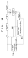
- FIG. 16 A block diagram of a conventional video encoder is presented in Fig. 16.
- an input picture signal is divided into a plurality of blocks and a motion vector indicating the motion relative to the picture of the preceding frame is estimated on a block-by-block basis.
- a motion vector indicating the motion relative to the picture of the preceding frame is estimated on a block-by-block basis.
- the preceding frame picture is subjected to motion compensation and the difference from the input picture is extracted.
- This differential signal is subjected to discrete cosine transform (DCT) quantization and variable length coding and, then, outputted.
- DCT discrete cosine transform
- the conventional transform encoder employs a single transform routine (transform matrix) on the assumption that the video image is stationary.
- transform matrix transform matrix
- KL variable matrix adaptive Karhunen-Loeve
- a motion compensated hybrid DPCM coding and decoding apparatus and method is known from US-A-4 999 705 (PURI). It calculates residual signals, applies on these signals a DCT conversion and a variable length coding. A motion compensation is performed with motion vectors and a block matching method.
- the models can be described as polygonals.
- SIGNAL PROCESSING. IMAGE COMMUNICATION, vol.3, no.2-3, June 1991, AMSTERDAM NL pages 259 - 274 ADOLPH ET AL '1.15 Mbits coding of video signals including global motion compensation' relates to a motion compensation for a block oriented hybrid DPCM, wherein a global motion estimation and a local fine motion estimation are applied.
- Fig.16 shows a block diagram of a conventional motion-compensated interframe predictive coding apparatus.
- a block motion estimation stage 711 determines a motion vector for the moving region of an input picture.
- a motion compensation stage 712 performs a motion compensation of the preceding frame picture according to the motion vector generated as above.
- the output information is the prediction error and motion vector of the resultant predicted picture.
- enhancing the coding efficiency of motion-compensated interframe predictive coding is tantamount to enhancing the accuracy of such a predicted picture, and enhancing the accuracy of the predicted picture, in turn, is equivalent to enhancing the accuracy of motion estimation.
- the conventional technology for motion estimation can be roughly divided into two methods, namely the block matching method and the gradient method.
- a motion vector is determined or each of discrete blocks.
- the sum of pixel value errors between the pixels in the corresponding positions of the block of interest and those in the block of the preceding frame which is shifted by a certain distance is then calculated. Error sums are calculated for various shifts and the shift with the smallest error sum is regarded as the motion vector of the particular block.
- This method insures validity within the range of search of motion vectors.
- this gradient method is able to take care of rotation, elongation/contraction, etc., and is not limited to parallel motions.
- the density value of each pixel is employed, the influence of noise is inevitable and, moreover, because only local gradients are taken into account, the method has the disadvantage that it cannot deal with large motions. Therefore, an attempt has been made to apply the gradient method to large regions such as blocks in lieu of individual pixels but the motion estimation is then limited to parallel motions.
- the first aspect of the invention which has been accomplished by the present inventors to overcome the above-mentioned disadvantages, has for its object to provide a video encoding apparatus which is able to make a sufficient compensation for the subject's motion to ensure a high coding efficiency.
- the second aspect of the invention has for its object to provide a video decoding apparatus which decodes the data encoded by the encoding apparatus.
- the video encoding apparatus comprises a video encoding apparatus comprising a video encoding apparatus comprising:
- the moving region is extracted from the input picture signal and a motion compensation is performed selectively for that region in the above manner, the efficiency of motion compensation around the contour of a moving object is improved. Moreover, by applying polygonal patches to the moving region to estimate fine motions, a motion compensation can be made for the deformation of the eyes and mouth.
- the video decoding apparatus to which the invention is directed comprises a video decoding apparatus comprising:
- the video decoding apparatus thus constructed is capable of decoding the data which has been encoded with a high coding efficiency, sufficiently compensating for the motion of the subject.
- Fig. 1 is a block diagram of the video encoding apparatus.
- the video signal input from an input terminal 1 is divided into a moving region and a still region in a moving object analyzer 2 where extraction of the moving region and estimation of motion parameters are carried out. Motion compensation of a reconstructed picture with the motion parameters is then carried out and the difference from the input picture is taken.
- This residual signal is coded in a residual coding stage 4.
- the motion parameter information and encoded residual information are converted to variable length codes in a variable length coding (VLC) stage 5 and outputted. Moreover, based on the motion parameter information and encoded residual information, a picture is reconstructed in a reconstruction stage 3.
- VLC variable length coding
- the residual coding stage 4 may be any apparatus that ensures an efficient expression of waveforms.
- a conditional replenishment apparatus which quantizes the residual signal and transmits any pixel value not equal to 0 with attachment of an address and an apparatus which performs a vector quantization expressing several pixels as a cluster by one code or a discrete cosine transform and subsequent quantisation for transmission can be employed.
- Fig. 2 is a block diagram showing an example of the moving object analyzer 2.
- the picture signal input from an input terminal 1 is subjected to extraction of a moving region in a moving region extraction stage 11.
- a global motion estimation stage 12 the motion parameter of the whole moving region is estimated.
- polygonal patch motion estimation stage 13 polygonal patches are applied to the moving region for the estimation of fine motions within the moving region.
- a motion compensation stage 14 uses the global motion parameter and polygonal motion parameter, a motion compensation stage 14 performs a motion compensation of a reconstructed input picture from an input terminal 10.
- the difference between the input picture and the motion-compensated picture is taken and outputted as a residual signal from an output terminal 16.
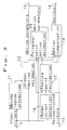
- the method of extracting the moving region in the moving region extraction stage 11 may comprise taking a time-wise difference between input picture, i.e. an interframe difference, and with the pixels whose values are larger than a threshold value being taken as the moving region, performing the elimination of isolated points for removal of noise components and the consolidation of areas to thereby extract the moving region.
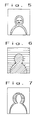
- An alternative method of extracting a moving region comprises, as illustrated in Fig.6, taking the interframe difference in the first place, searching for the edges of a moving object from both sides and extracting the internal area defined by the edges as the moving region.
- the global motion estimation in the global motion estimation stage 12 performs a mapping of the shift of a given point (x,y) to another point (x',y') as shown in Fig. 7 and represented by the following equation (1) and determines motion parameters a-f.
- a-d are parameters representing rotation, enlargement, reduction and deformation, and e and f are parameters representing parallel movements.
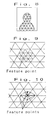
- the polygonal patch motion estimation in the polygonal patch motion estimation stage 13 comprises mapping the picture preceding by one frame with the global motion parameter and applying polygonal patches to the moving region as shown in Fig. 8. Triangular patches are shown in the illustration. The vertices of each triangle are moved so as to minimise the error from the current picture. The image within the triangle is mapped by affine transform. The expression for this affine transform is identical with equation (1). The parameters vary with different triangles. All the information to be transmitted is the amount of shift of each vertex.
- the parameters k, l and m can be determined from the amounts of shift of the respective vertices of the triangular patch in the direction of the luminance scale.
- Fig. 3 is a block diagram showing another example of the moving object analyzer 2.
- a feature point extractor 17 and a human object detector 18 are included.
- the feature point extraction stage 17 extracts feature points such as the eyes and mouth of a human object from the reconstituted picture. For the area around the feature point, the triangular patch is reduced in size to deal with finer motions as shown in Fig. 9.
- An alternative procedure shown in Fig. 10, comprises applying triangular patches conforming to feature points for motion compensation and then applying-triangular patches of fixed shape to make a further motion compensation. While feature points can be extracted from the input picture, extraction from the reconstituted image is more advantageous in that the extraction can be performed at the reception side as well, so that the transmission of topological data on the feature point can be omitted.
- This procedure for extracting feature points provides for extraction with high probabilities when modelling is possible to a certain extent as it is the case of a human face but can hardly perform extractions from ordinary scenes. Therefore, an automatic inquiry is made in a character detection stage 18 to find whether the subject of interest is a human object or not, or in the case of ordinary scenes the feature point extraction mode is switched manually to the mode using fixed triangular patches.
- a human object encoder and a general image encoder may be provided for selective use.
- Fig. 4 is a block diagram showing still another example of the moving object analyzer according to this invention.
- this analyzer includes a background picture construction stage 19.
- the pixels standing still for a long time in the reconstructed picture are written into a background memory to construct a background picture.
- This background picture is used when the background has appeared from behind a moving object.
- the background which appears from behind the moving object is the area which belonged to the moving region in the preceding frame and has become a still region in the current frame. Since this background compensation area can be recognised on the reception side, too, the transmission of the area information can be omitted.
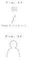
- differential chain code As a means for transmitting moving region contour information, there is differential chain code. As shown in Fig. 11, eight allowable directions of movement are numbered and initially a relevant number is transmitted and, thereafter, only the difference from the preceding direction is transmitted. Where a strictly exact contour information need not be transmitted, only the locations of representative points are transmitted and the intervals are interpolated using a curve such as a spline curve as shown in Fig. 12. When this technique is applied to motion pictures, only the amounts of offset of feature points are transmitted so that the data size can be further reduced.
- Fig. 13 is a one-dimensional representation of background and moving region signals.
- the background and moving region are interconnected in a smooth line because of the blunting of signals by camera blur and signal processing. If the moving region shifting to the left is cut and pasted to the background, the borderline will be sharp and prominent. Therefore, the signals close to the borderline are gently attenuated and overlapped to achieve a smooth joint.
- Fig. 14 is a block diagram showing the transmission of a picture of the human face, in which (a) represents a transmitter and (b) a receiver.
- the reference numeral 100 indicates a coding stage which is generally called a parameter encoder. It may for example be a coder which segregates the moving region of this invention, a coder which performs a segregation along the contour or profile, a model based coder, an analysis-synthesis coder, or an intellectual coder.
- the reference numeral 102 indicates the conventional waveform coder.
- the input signal is checked in a parameter decoder 104 to see whether it contains the image of a face, for instance, and in a selector 106 stage, a change of mode is performed either automatically or manually.
- the picture is transmitted thrdugh the parameter coder 100 when the image of a face is included and through the waveform coder 102 when such image is not included.
- a selector 108 makes a change of mode either automatically or manually and the input signal is fed to a parameter decoder 110 when it includes the image of a face or to a waveform decoder 112 when no such image is included.
- Figure 15 shows the video decoding apparatus 200 according to the second aspect of the invention for decoding the data coded by the video encoding apparatus shown in Fig. 1.
- the coded data from the video encoding apparatus is supplied to an input terminal 201 of this video decoding apparatus 200, where the variable length code is decoded in a variable length decoder (VLD) 202, which then outputs motion parameters and a residual code.
- the motion parameter includes moving region information, global motion parameter and polygon patch motion parameters.
- a residual code decoder 204 decodes the residual code and outputs a residual signal.
- a global motion compensation circuit 207 receives the decoded preceding frame picture stored in a frame memory 208, moving region information and global motion parameter and performs a motion compensation of the whole moving region and outputs a global motion-compensated picture.
- a polygonal patch motion compensation circuit 206 receives the global motion-compensated picture and the polygonal patch motion parameters, performs a local motion compensation within the moving region and outputs a motion-compensated prediction picture.
- An adder 205 adds up the motion-compensated prediction picture and the residual code to construct a decoded picture, outputs the decoded picture from an output terminal 209 and, at the same time, feeds it to the frame memory 208.
Description
- This invention relates to video encoding and decoding apparatus for use in video motion compensated interframe predictive coding.
- The video encoding technology has been utilised in the following picture communication, broadcasting and storage applications;
- (i) Transmission of still pictures, for example in facsimile telegraphy, at the highest possible speed through picture coding;
- (ii) Transmission of motion pictures in video conferencing, videophone and other fields within the narrowest possible band and/or the lowest possible bit rate by the utilisation of picture coding;
- (iii) Recording of picture information in a disk or memory for the most efficient storage of as much image data as possible through picture coding.
-
- A block diagram of a conventional video encoder is presented in Fig. 16.
- As shown, an input picture signal is divided into a plurality of blocks and a motion vector indicating the motion relative to the picture of the preceding frame is estimated on a block-by-block basis. Using this motion vector, the preceding frame picture is subjected to motion compensation and the difference from the input picture is extracted. This differential signal is subjected to discrete cosine transform (DCT) quantization and variable length coding and, then, outputted.
- As suggested by the use of DCT, the conventional transform encoder employs a single transform routine (transform matrix) on the assumption that the video image is stationary. Moreover, even in the variable matrix adaptive Karhunen-Loeve (KL) transform coding apparatus employing a plurality of transform matrices which are selectively accessed, technologies with poor operational efficiencies such as the method involving a total search for selecting one transform matrix for a fixed quantisation procedure have been explored and there has been no optimal coding apparatus for video information. Furthermore, as the technology for selecting the optimum transform from among a plurality of available KL transforms, the technique using distances in the auto-correlation matrix space of the input signal and the technique assuming the perpetual existence of directionality in images have been available but since these techniques are not optimal from the standpoint of minimizing the coding error a degradation of coding performance has been inevitable.
- Meanwhile, even when the optimum transform could be selected in the conventional video coding apparatus illustrated in Fig. 16, motion compensations had to be invariably carried out by parallel shifting with respect to the input video signal on a block-by-block basis and the prediction error transform was carried out for each block. However, because prediction errors cannot be fully transmitted at a low bit rate, a block-shaped distortion takes place to detract from the picture quality. Furthermore, since the background area which appears behind a moving object cannot be predicted, the coding efficiency is inevitably low.
- A motion compensated hybrid DPCM coding and decoding apparatus and method is known from US-A-4 999 705 (PURI). It calculates residual signals, applies on these signals a DCT conversion and a variable length coding. A motion compensation is performed with motion vectors and a block matching method.
- The article SIGNAL PROCESSING. IMAGE COMMUNICATION, vol.1, no.2, October 1989, AMSTERDAM NL pages 117 - 138 MUSMANN ET AL 'object-oriented analysis-synthesis coding of moving images', shows a non-block oriented coding method which uses 3D-models for coding purposes and for avoiding blocking artefacts.
- The models can be described as polygonals. In SIGNAL PROCESSING. IMAGE COMMUNICATION, vol.3, no.2-3, June 1991, AMSTERDAM NL pages 259 - 274 ADOLPH ET AL '1.15 Mbits coding of video signals including global motion compensation', relates to a motion compensation for a block oriented hybrid DPCM, wherein a global motion estimation and a local fine motion estimation are applied.
- In relation to video motion estimating apparatus, the high efficiency coding technology for motion pictures was developed to meet the following requirements.
- (i) To transmit video signals in a situation where the available frequency band will be remarkably limited as it is the case with wireless videophone.
- (ii) To transmit a video image of high picture quality using a communication channel of comparatively narrow band, such as analog channel.
- (iii) To accumulate a longer time series of picture data in a recording medium.
-
- Meanwhile, it is known that a very high correlation generally exists between consecutive video frames and as a technique for high efficiency coding which lands on this characteristic; there is a motion-compensated interframe predictive coding method.
- Fig.16 shows a block diagram of a conventional motion-compensated interframe predictive coding apparatus.
- A block
motion estimation stage 711 determines a motion vector for the moving region of an input picture. - A
motion compensation stage 712 performs a motion compensation of the preceding frame picture according to the motion vector generated as above. The output information is the prediction error and motion vector of the resultant predicted picture. - Therefore, enhancing the coding efficiency of motion-compensated interframe predictive coding is tantamount to enhancing the accuracy of such a predicted picture, and enhancing the accuracy of the predicted picture, in turn, is equivalent to enhancing the accuracy of motion estimation.
- The conventional technology for motion estimation can be roughly divided into two methods, namely the block matching method and the gradient method.
- In the block matching method, a motion vector is determined or each of discrete blocks. The sum of pixel value errors between the pixels in the corresponding positions of the block of interest and those in the block of the preceding frame which is shifted by a certain distance is then calculated. Error sums are calculated for various shifts and the shift with the smallest error sum is regarded as the motion vector of the particular block.
- This method insures validity within the range of search of motion vectors.
- However, in the motion estimation by this block matching method, only parallel motions are taken into consideration. Thus, motions not parallel, such as a rotation, elongation/contraction, or deformation cannot be estimated. Moreover, because it involves a total search for motion vector candidates within the estimation range, a time-consuming operation is required.
- The gradient method was proposed as a technique for determining the motion vector for each pixel. It is known that the motion vector (Vx, Vy) of a point (x, y) on the picture is approximated by the following equation:
- By way of illustration, when a pixel of interest in the
current frame 713 is represented by a closed circle as in Fig. 17, the difference of its density from that of a pixel situated in the x direction (an open circle) and from that of a pixel situated in the y direction (an open circle) can be expressed as Ex and Ey, respectively. - Moreover, when the pixel in preceding
frame 714 which is situated in the position corresponding to said pixel of interest is represented by a closed circle (x', y') the difference in density between this pixel value and the pixel value of the pixel of interest in thecurrent frame 713 can be expressed by Et. - In this manner, one Et is determined for each pixel of interest and (Vx, Vy) are determined by varying Ex and Ey in the X and Y directions, respectively, in such a manner that the right-hand term of the above equation will become equal to zero.
- Because motion estimations are thus performed for respective pixels, this gradient method is able to take care of rotation, elongation/contraction, etc., and is not limited to parallel motions. However, because the density value of each pixel is employed, the influence of noise is inevitable and, moreover, because only local gradients are taken into account, the method has the disadvantage that it cannot deal with large motions. Therefore, an attempt has been made to apply the gradient method to large regions such as blocks in lieu of individual pixels but the motion estimation is then limited to parallel motions.
- In the conventional video coding method, motion compensation is carried out by parallel shift for each block. Therefore, when a block extends into both the still region and the moving region, the available choice is either to make a parallel shift in conformity with the moving region or do so in conformity with the still region. In either case, the differential signal in one of the two regions is increased. Moreover, in the case where the subject changes its shape as it is the case with the eyes and mouth of a character, too, no sufficient motion compensation can be made by the mere parallel shift of the block. The same applies when the subject makes a spin or is increased or decreased in size as the result of zooming of the camera.
- The first aspect of the invention, which has been accomplished by the present inventors to overcome the above-mentioned disadvantages, has for its object to provide a video encoding apparatus which is able to make a sufficient compensation for the subject's motion to ensure a high coding efficiency.
- The second aspect of the invention has for its object to provide a video decoding apparatus which decodes the data encoded by the encoding apparatus.
- It should be noticed that in the conventional video encoder described so far, the optimum matrix selection method has not been available even when a plurality of transform matrices are available and, moreover, because of its inability to preclude said block-like distortion and to deal with a sudden uncovering of the background, the coding efficiency is inevitably low.
- The video encoding apparatus according to the invention comprises a video encoding apparatus comprising a video encoding apparatus comprising:
- a moving object analyzing means for extracting a moving object from an input video signal, analyzing its motion and outputting motion parameters and a residual signal, the residual signal being the difference between the input video signal and a reconstructed video signal which has been subjected to motion compensation;
- a residual coding means for encoding said residual signal from said moving object analyzing means to form encoded residual data;
- a reconstruction means for generating the reconstructed video signal using the motion parameters from the moving object analyzing means and the encoded residual data from the residual coding means; and
- a variable length coding means which performs a variable length coding of said motion parameters and encoded residual data, wherein the moving object analyzing means comprises:
- a global motion estimating means for estimating a global motion parameter relating to the motion of the whole moving region within the input video signal,
- a polygonal patch motion estimating means for estimating fine motions within the moving region, by estimating polygonal patch motion parameters, relating to the motion of parts of the moving region, by applying polygonal patches to the moving region within the input video signal or reconstructed video signal, and
- a motion compensating means for performing motion compensation of the reconstructed video signal using the global motion parameters and polygonal patch motion parameters.
-
- Thus, since the moving region is extracted from the input picture signal and a motion compensation is performed selectively for that region in the above manner, the efficiency of motion compensation around the contour of a moving object is improved. Moreover, by applying polygonal patches to the moving region to estimate fine motions, a motion compensation can be made for the deformation of the eyes and mouth.
- The video decoding apparatus to which the invention is directed comprises a video decoding apparatus comprising:
- a variable length decoding means for receiving variable length coded data, decoding the coded data and resolving it into a global motion parameter, polygonal patch motion parameters and a residual code, wherein the global motion parameter relates to the motion of the whole moving region within a video signal, and wherein the polygonal patch motion parameters relate to the motion of parts of the moving region within the video signal;
- a residual code decoding means for decoding the residual code from the variable length decoding means and outputting a residual signal;
- a global motion compensating means for performing motion compensation of the entire moving region using the decoded video signal of a preceding frame stored in a frame memory and the global motion parameter output from the variable length decoding means and outputting a global motion compensated video signal,
- a polygonal patch compensating means for performing local motion compensation within the moving region using the global motion compensated image output from the global motion compensating means and the polygonal patch motion parameters output from the variable length decoding means and outputting a motion compensated prediction video signal; and
- an adding means for adding the motion compensated prediction image from the polygonal patch compensating means and the residual code output from the residual code decoding means to construct a decoded video signal, and outputting the decoded video signal to a frame memory.
-
- The video decoding apparatus thus constructed is capable of decoding the data which has been encoded with a high coding efficiency, sufficiently compensating for the motion of the subject.
-
- Fig. 1 is a block diagram of the video encoding apparatus according to one embodiment of the first aspect of the invention;
- Fig. 2 is a block diagram showing an example of the moving picture analyzing stage of the first aspect of the invention;
- Fig. 3 is a block diagram showing another example of the moving picture analyzing stage of the first aspect of the invention;
- Fig. 4 is a block diagram showing still another example of the moving picture analyzing stage of the first aspect of the invention;
- Fig. 5 is a schematic diagram illustrating the extraction of a moving region by elimination of isolated points of interframe difference and regional consolidation;
- Fig. 6 is a schematic diagram describing the mode of extraction of a moving region using the area within a dynamic border as the moving region;
- Fig. 7 is a diagrammatic representation of a global motion estimation procedure;
- Fig. 8 is a diagrammatic representation of a triangular patch motion estimation procedure;
- Fig. 9 is a diagrammatic representation of the method of a performing a motion compensation by diminishing the size of the triangular patch around a feature point;
- Fig. 10 is a diagrammatic representation of the method of performing a motion compensation by modifying the configuration of triangular patches according to feature points;
- Fig. 11 is a diagrammatic illustration describing the differential chain coding procedure;
- Fig. 12 is a diagrammatic representation of the selective transmission of representative points and interpolation between the points for construction of a contour or borderline;
- Fig. 13 is a diagram illustrating the method of merging a background and a moving region;
- Fig. 14 is a block diagram for the transmission of a human face, where (a) represents a transmitter and (b) a receiver;
- Fig. 15 is a block diagram of the video decoding apparatus according to the second aspect of the invention;
- Fig. 16 is a block diagram showing a prior art motion compensated interframe predictive coding method; and
- Fig. 17 is a diagram describing the conventional gradient method.
-
- The video encoding apparatus according to one embodiment of the first invention is now described in detail, referring to Figs. 1-14.
- Fig. 1 is a block diagram of the video encoding apparatus.
- The video signal input from an
input terminal 1 is divided into a moving region and a still region in a movingobject analyzer 2 where extraction of the moving region and estimation of motion parameters are carried out. Motion compensation of a reconstructed picture with the motion parameters is then carried out and the difference from the input picture is taken. This residual signal is coded in aresidual coding stage 4. The motion parameter information and encoded residual information are converted to variable length codes in a variable length coding (VLC)stage 5 and outputted. Moreover, based on the motion parameter information and encoded residual information, a picture is reconstructed in a reconstruction stage 3. - The
residual coding stage 4 may be any apparatus that ensures an efficient expression of waveforms. For example, a conditional replenishment apparatus which quantizes the residual signal and transmits any pixel value not equal to 0 with attachment of an address and an apparatus which performs a vector quantization expressing several pixels as a cluster by one code or a discrete cosine transform and subsequent quantisation for transmission can be employed. - Fig. 2 is a block diagram showing an example of the moving
object analyzer 2. - The picture signal input from an
input terminal 1 is subjected to extraction of a moving region in a movingregion extraction stage 11. In a globalmotion estimation stage 12 the motion parameter of the whole moving region is estimated. Then, in a polygonal patchmotion estimation stage 13, polygonal patches are applied to the moving region for the estimation of fine motions within the moving region. Using the global motion parameter and polygonal motion parameter, amotion compensation stage 14 performs a motion compensation of a reconstructed input picture from aninput terminal 10. The difference between the input picture and the motion-compensated picture is taken and outputted as a residual signal from anoutput terminal 16. - The method of extracting the moving region in the moving
region extraction stage 11 may comprise taking a time-wise difference between input picture, i.e. an interframe difference, and with the pixels whose values are larger than a threshold value being taken as the moving region, performing the elimination of isolated points for removal of noise components and the consolidation of areas to thereby extract the moving region. - However, since differences are almost nil in the flat parts of a moving object in this method, the moving region is broken down into many isolated moving areas as illustrated in Fig. 5 with the result that there occurs the problem of an increased number of moving regions.
- An alternative method of extracting a moving region comprises, as illustrated in Fig.6, taking the interframe difference in the first place, searching for the edges of a moving object from both sides and extracting the internal area defined by the edges as the moving region.
- In this method, there occurs no division of the moving region. Moreover, a more accurate extraction can be performed by searching for the edges of a moving object from top and bottom as well as from both sides.
- The global motion estimation in the global
motion estimation stage 12 performs a mapping of the shift of a given point (x,y) to another point (x',y') as shown in Fig. 7 and represented by the following equation (1) and determines motion parameters a-f. - It should be understood that a-d are parameters representing rotation, enlargement, reduction and deformation, and e and f are parameters representing parallel movements.

- The polygonal patch motion estimation in the polygonal patch
motion estimation stage 13 comprises mapping the picture preceding by one frame with the global motion parameter and applying polygonal patches to the moving region as shown in Fig. 8. Triangular patches are shown in the illustration. The vertices of each triangle are moved so as to minimise the error from the current picture. The image within the triangle is mapped by affine transform. The expression for this affine transform is identical with equation (1). The parameters vary with different triangles. All the information to be transmitted is the amount of shift of each vertex. - When a moving object moves, the condition of impinging light changes so that there may be a difference in luminance value between the corresponding points. To compensate for this difference, the vertices of the triangle must be shifted not only within the two-dimensional plane but also on the luminance scale. Assuming that the amount of luminosity compensation on the luminance scale for the shift of a given point (x,y) to another point (x',y') is z', there holds the equation
- The parameters k, l and m can be determined from the amounts of shift of the respective vertices of the triangular patch in the direction of the luminance scale.
- Fig. 3 is a block diagram showing another example of the moving
object analyzer 2. - The differences from Fig. 2 is that a
feature point extractor 17 and ahuman object detector 18 are included. - The feature
point extraction stage 17 extracts feature points such as the eyes and mouth of a human object from the reconstituted picture. For the area around the feature point, the triangular patch is reduced in size to deal with finer motions as shown in Fig. 9. - An alternative procedure, shown in Fig. 10, comprises applying triangular patches conforming to feature points for motion compensation and then applying-triangular patches of fixed shape to make a further motion compensation. While feature points can be extracted from the input picture, extraction from the reconstituted image is more advantageous in that the extraction can be performed at the reception side as well, so that the transmission of topological data on the feature point can be omitted.
- This procedure for extracting feature points provides for extraction with high probabilities when modelling is possible to a certain extent as it is the case of a human face but can hardly perform extractions from ordinary scenes. Therefore, an automatic inquiry is made in a
character detection stage 18 to find whether the subject of interest is a human object or not, or in the case of ordinary scenes the feature point extraction mode is switched manually to the mode using fixed triangular patches. As a further alternative, a human object encoder and a general image encoder may be provided for selective use. - Fig. 4 is a block diagram showing still another example of the moving object analyzer according to this invention.
- The difference from Fig. 2 is that this analyzer includes a background
picture construction stage 19. - The pixels standing still for a long time in the reconstructed picture are written into a background memory to construct a background picture. This background picture is used when the background has appeared from behind a moving object. The background which appears from behind the moving object is the area which belonged to the moving region in the preceding frame and has become a still region in the current frame. Since this background compensation area can be recognised on the reception side, too, the transmission of the area information can be omitted.
- As a means for transmitting moving region contour information, there is differential chain code. As shown in Fig. 11, eight allowable directions of movement are numbered and initially a relevant number is transmitted and, thereafter, only the difference from the preceding direction is transmitted. Where a strictly exact contour information need not be transmitted, only the locations of representative points are transmitted and the intervals are interpolated using a curve such as a spline curve as shown in Fig. 12. When this technique is applied to motion pictures, only the amounts of offset of feature points are transmitted so that the data size can be further reduced.
- In merging the still region, background compensation region and moving region, cut and paste method is visually unacceptable because the contour is accentuated. Fig. 13 is a one-dimensional representation of background and moving region signals. The background and moving region are interconnected in a smooth line because of the blunting of signals by camera blur and signal processing. If the moving region shifting to the left is cut and pasted to the background, the borderline will be sharp and prominent. Therefore, the signals close to the borderline are gently attenuated and overlapped to achieve a smooth joint.
- Fig. 14 is a block diagram showing the transmission of a picture of the human face, in which (a) represents a transmitter and (b) a receiver.
- Referring to the transmitter, the
reference numeral 100 indicates a coding stage which is generally called a parameter encoder. It may for example be a coder which segregates the moving region of this invention, a coder which performs a segregation along the contour or profile, a model based coder, an analysis-synthesis coder, or an intellectual coder. Thereference numeral 102 indicates the conventional waveform coder. The input signal is checked in aparameter decoder 104 to see whether it contains the image of a face, for instance, and in aselector 106 stage, a change of mode is performed either automatically or manually. The picture is transmitted thrdugh theparameter coder 100 when the image of a face is included and through thewaveform coder 102 when such image is not included. - On the receiver side, too, a
selector 108 makes a change of mode either automatically or manually and the input signal is fed to aparameter decoder 110 when it includes the image of a face or to awaveform decoder 112 when no such image is included. - Figure 15 shows the
video decoding apparatus 200 according to the second aspect of the invention for decoding the data coded by the video encoding apparatus shown in Fig. 1. - The coded data from the video encoding apparatus is supplied to an
input terminal 201 of thisvideo decoding apparatus 200, where the variable length code is decoded in a variable length decoder (VLD) 202, which then outputs motion parameters and a residual code. The motion parameter includes moving region information, global motion parameter and polygon patch motion parameters. - A
residual code decoder 204 decodes the residual code and outputs a residual signal. - A global
motion compensation circuit 207 receives the decoded preceding frame picture stored in aframe memory 208, moving region information and global motion parameter and performs a motion compensation of the whole moving region and outputs a global motion-compensated picture. - A polygonal patch
motion compensation circuit 206 receives the global motion-compensated picture and the polygonal patch motion parameters, performs a local motion compensation within the moving region and outputs a motion-compensated prediction picture. - An
adder 205 adds up the motion-compensated prediction picture and the residual code to construct a decoded picture, outputs the decoded picture from anoutput terminal 209 and, at the same time, feeds it to theframe memory 208. - In the above manner, the data coded by the video encoding apparatus illustrated in Fig. 1 is decoded.
Claims (7)
- A video encoding apparatus comprising:the moving object analyzing means (2) comprises:a moving object analyzing means (2) for extracting a moving object from an input video signal (1), analyzing its motion and outputting motion parameters and a residual signal, the residual signal being the difference between the input video signal and a reconstructed video signal which has been subjected to motion compensation;a residual coding means (4) for encoding said residual signal from said moving object analyzing means (2) to form encoded residual data;a reconstruction means (3) for generating the reconstructed video signal using the motion parameters from the moving object analyzing means (2) and the encoded residual data from the residual coding means (4) ; anda variable length coding means (5) which performs a variable length coding of said motion parameters and encoded residual data, whereina global motion estimating means (12) for estimating a global motion parameter relating to the motion of the whole moving region within the input video signal,a polygonal patch motion estimating means (13) for estimating fine motions within the moving region, by estimating polygonal patch motion parameters, relating to the motion of parts of the moving region, by applying polygonal patches to the moving region within the input video signal or reconstructed video signal, anda motion compensating means (14) for performing motion compensation of the reconstructed video signal using the global motion parameters and polygonal patch motion parameters.
- A video encoding apparatus as claimed in claim 1, wherein the moving object analyzing means (2) comprises a moving region extraction means (11) for extracting a moving region from the input video signal.
- A video encoding apparatus as claimed in claim 2, having feature extraction means (17) for extracting feature points from the moving region of the reconstructed video signal, and applying the polygonal patches to these regions, with the vertices of the polygons being fitted to the feature points.
- A video encoding apparatus as claimed in claim 3, wherein the polygonal patch motion estimating means (13) estimates the polygonal patch parameters by applying small polygonal patches to the vicinity of the feature points in the moving region extracted by the feature point extracting means (17), and additionally applying larger polygonal patches to the moving region.
- A video encoding apparatus as claimed in claim 4, wherein the moving object analyzing means (2) takes a time-wise difference from input video signals, searches for a region with a greater difference from top, bottom and both sides, and selects the region as the moving region.
- A video encoding apparatus as claimed in claim 1, having a background video signal construction means (19) for constructing a background video signal from the reconstructed video signal, and wherein the compensating means includes compensation of the background appearing from behind the moving region by the background video signal constructed by the background video signal constructing means (19).
- A video decoding apparatus comprising:a variable length decoding means (202) for receiving variable length coded data, decoding the coded data and resolving it into a global motion parameter, polygonal patch motion parameters and a residual code, wherein the global motion parameter relates to the motion of the whole moving region within a video signal, and wherein the polygonal patch motion parameters relate to the motion of parts of the moving region within the video signal;a residual code decoding means (204) for decoding the residual code from the variable length decoding means and outputting a residual signal;a global motion compensating means (207) for performing motion compensation of the entire moving region using the decoded video signal of a preceding frame stored in a frame memory (208) and the global motion parameter output from the variable length decoding means (202) and outputting a global motion compensated video signal,a polygonal patch compensating means (206) for performing local motion compensation within the moving region using the global motion compensated image output from the global motion compensating means (207) and the polygonal patch motion parameters output from the variable length decoding means (202) and outputting a motion compensated prediction video signal; andan adding-means (205) for adding the motion compensated prediction image from the polygonal patch compensating means (206) and the residual code output from the residual code decoding means (204) to construct a decoded video signal, and outputting the decoded video signal to a frame memory (208).
Applications Claiming Priority (12)
| Application Number | Priority Date | Filing Date | Title |
|---|---|---|---|
| JP4365593 | 1993-03-04 | ||
| JP43655/93 | 1993-03-04 | ||
| JP4365593 | 1993-03-04 | ||
| JP20735993 | 1993-08-23 | ||
| JP5207359A JPH0767111A (en) | 1993-08-23 | 1993-08-23 | Motion estimating device for image |
| JP207359/93 | 1993-08-23 | ||
| JP24094093 | 1993-09-28 | ||
| JP24094093 | 1993-09-28 | ||
| JP240940/93 | 1993-09-28 | ||
| JP332856/93 | 1993-12-27 | ||
| JP33285693A JP3405788B2 (en) | 1993-03-04 | 1993-12-27 | Video encoding device and video decoding device |
| JP33285693 | 1993-12-27 |
Publications (3)
| Publication Number | Publication Date |
|---|---|
| EP0614318A2 EP0614318A2 (en) | 1994-09-07 |
| EP0614318A3 EP0614318A3 (en) | 1995-05-17 |
| EP0614318B1 true EP0614318B1 (en) | 1999-12-01 |
Family
ID=27461399
Family Applications (1)
| Application Number | Title | Priority Date | Filing Date |
|---|---|---|---|
| EP94301527A Expired - Lifetime EP0614318B1 (en) | 1993-03-04 | 1994-03-03 | Video encoder and decoder |
Country Status (3)
| Country | Link |
|---|---|
| US (1) | US5592228A (en) |
| EP (1) | EP0614318B1 (en) |
| DE (1) | DE69421837T2 (en) |
Cited By (20)
| Publication number | Priority date | Publication date | Assignee | Title |
|---|---|---|---|---|
| DE102007049740A1 (en) | 2007-10-16 | 2009-04-23 | Technische Universität Braunschweig Carolo-Wilhelmina | Method for determining two-dimensional motion vector fields in an image sequence and image processing device for this purpose |
| US7646810B2 (en) | 2002-01-25 | 2010-01-12 | Microsoft Corporation | Video coding |
| US7664177B2 (en) | 2003-09-07 | 2010-02-16 | Microsoft Corporation | Intra-coded fields for bi-directional frames |
| US7685305B2 (en) | 1999-03-12 | 2010-03-23 | Microsoft Corporation | Media coding for loss recovery with remotely predicted data units |
| US7924920B2 (en) | 2003-09-07 | 2011-04-12 | Microsoft Corporation | Motion vector coding and decoding in interlaced frame coded pictures |
| US8085844B2 (en) | 2003-09-07 | 2011-12-27 | Microsoft Corporation | Signaling reference frame distances |
| US8189666B2 (en) | 2009-02-02 | 2012-05-29 | Microsoft Corporation | Local picture identifier and computation of co-located information |
| US8254455B2 (en) | 2007-06-30 | 2012-08-28 | Microsoft Corporation | Computing collocated macroblock information for direct mode macroblocks |
| US8290288B2 (en) | 1998-11-30 | 2012-10-16 | Microsoft Corporation | Encoding macroblock type and coded block pattern information |
| US8374245B2 (en) | 2002-06-03 | 2013-02-12 | Microsoft Corporation | Spatiotemporal prediction for bidirectionally predictive(B) pictures and motion vector prediction for multi-picture reference motion compensation |
| US8379722B2 (en) | 2002-07-19 | 2013-02-19 | Microsoft Corporation | Timestamp-independent motion vector prediction for predictive (P) and bidirectionally predictive (B) pictures |
| US8428374B2 (en) | 2001-12-17 | 2013-04-23 | Microsoft Corporation | Skip macroblock coding |
| US8625669B2 (en) | 2003-09-07 | 2014-01-07 | Microsoft Corporation | Predicting motion vectors for fields of forward-predicted interlaced video frames |
| US8634413B2 (en) | 2004-12-30 | 2014-01-21 | Microsoft Corporation | Use of frame caching to improve packet loss recovery |
| US8687697B2 (en) | 2003-07-18 | 2014-04-01 | Microsoft Corporation | Coding of motion vector information |
| US8902971B2 (en) | 2004-07-30 | 2014-12-02 | Euclid Discoveries, Llc | Video compression repository and model reuse |
| US9077960B2 (en) | 2005-08-12 | 2015-07-07 | Microsoft Corporation | Non-zero coefficient block pattern coding |
| US9532069B2 (en) | 2004-07-30 | 2016-12-27 | Euclid Discoveries, Llc | Video compression repository and model reuse |
| US9578345B2 (en) | 2005-03-31 | 2017-02-21 | Euclid Discoveries, Llc | Model-based video encoding and decoding |
| US9743078B2 (en) | 2004-07-30 | 2017-08-22 | Euclid Discoveries, Llc | Standards-compliant model-based video encoding and decoding |
Families Citing this family (115)
| Publication number | Priority date | Publication date | Assignee | Title |
|---|---|---|---|---|
| US6052414A (en) * | 1994-03-30 | 2000-04-18 | Samsung Electronics, Co. Ltd. | Moving picture coding method and apparatus for low bit rate systems using dynamic motion estimation |
| DE69525898T2 (en) * | 1994-05-30 | 2002-11-14 | Nippon Telegraph & Telephone | MOTION IMAGE ENCODING AND DECODING DEVICE |
| US6313863B1 (en) * | 1994-07-29 | 2001-11-06 | Canon Kabushiki Kaisha | Image communication apparatus and system |
| JP2870415B2 (en) * | 1994-08-22 | 1999-03-17 | 日本電気株式会社 | Area division method and apparatus |
| JPH0865681A (en) * | 1994-08-25 | 1996-03-08 | Sony Corp | Motion vector detector and motion compensating prediction encoding system using the detector |
| US5767911A (en) | 1994-12-20 | 1998-06-16 | Matsushita Electric Industrial Co., Ltd. | Object-based digital image predictive coding transfer method and apparatus, and decoding apparatus |
| US6020925A (en) * | 1994-12-30 | 2000-02-01 | Daewoo Electronics Co., Ltd. | Method and apparatus for encoding a video signal using pixel-by-pixel motion prediction |
| KR0181029B1 (en) * | 1995-03-15 | 1999-05-01 | 배순훈 | Apparatus for selecting a feature point by using edge |
| KR0181059B1 (en) * | 1995-03-18 | 1999-05-01 | 배순훈 | A contour approximation apparatus for representing a contour of an object |
| KR100249028B1 (en) * | 1995-03-20 | 2000-03-15 | 전주범 | Apparatus for effectively encoding/decoding video signals having stationary object |
| KR0171120B1 (en) * | 1995-04-29 | 1999-03-20 | 배순훈 | Method and apparatus for determining motion region in video coding technique using feature point based motion compensation |
| US5923786A (en) * | 1995-07-17 | 1999-07-13 | Sony Corporation | Method and device for encoding and decoding moving images |
| CN1110957C (en) * | 1995-07-21 | 2003-06-04 | 大宇电子株式会社 | Method for dividing and estimating motion of moving objective by layering structure of motion model |
| JP3933691B2 (en) * | 1995-09-12 | 2007-06-20 | コーニンクレッカ フィリップス エレクトロニクス エヌ ヴィ | Hybrid waveform and model-based encoding and decoding of image signals |
| US5883678A (en) | 1995-09-29 | 1999-03-16 | Kabushiki Kaisha Toshiba | Video coding and video decoding apparatus for reducing an alpha-map signal at a controlled reduction ratio |
| US6307967B1 (en) | 1995-09-29 | 2001-10-23 | Kabushiki Kaisha Toshiba | Video coding and video decoding apparatus |
| US6754268B1 (en) | 1995-09-29 | 2004-06-22 | Kabushiki Kaisha Toshiba | Video coding and video decoding apparatus |
| US5959673A (en) * | 1995-10-05 | 1999-09-28 | Microsoft Corporation | Transform coding of dense motion vector fields for frame and object based video coding applications |
| US5777678A (en) * | 1995-10-26 | 1998-07-07 | Sony Corporation | Predictive sub-band video coding and decoding using motion compensation |
| JP3788823B2 (en) * | 1995-10-27 | 2006-06-21 | 株式会社東芝 | Moving picture encoding apparatus and moving picture decoding apparatus |
| KR100209793B1 (en) * | 1995-10-28 | 1999-07-15 | 전주범 | Apparatus for encoding/decoding a video signals by using feature point based motion estimation |
| JP2798035B2 (en) * | 1996-01-17 | 1998-09-17 | 日本電気株式会社 | Motion compensated inter-frame prediction method using adaptive motion vector interpolation |
| US5692063A (en) * | 1996-01-19 | 1997-11-25 | Microsoft Corporation | Method and system for unrestricted motion estimation for video |
| US5799113A (en) * | 1996-01-19 | 1998-08-25 | Microsoft Corporation | Method for expanding contracted video images |
| US5787203A (en) * | 1996-01-19 | 1998-07-28 | Microsoft Corporation | Method and system for filtering compressed video images |
| EP1229740A3 (en) * | 1996-01-22 | 2005-02-09 | Matsushita Electric Industrial Co., Ltd. | Method and device for digital image encoding and decoding |
| JP2888186B2 (en) * | 1996-02-19 | 1999-05-10 | 富士ゼロックス株式会社 | Image encoding device and image decoding device |
| US5778100A (en) * | 1996-03-08 | 1998-07-07 | Lucent Technologies Inc. | Method and apparatus for reducing the bit rate in a video object planes sequence coder |
| US5764814A (en) * | 1996-03-22 | 1998-06-09 | Microsoft Corporation | Representation and encoding of general arbitrary shapes |
| US5778098A (en) * | 1996-03-22 | 1998-07-07 | Microsoft Corporation | Sprite coding |
| US6215910B1 (en) | 1996-03-28 | 2001-04-10 | Microsoft Corporation | Table-based compression with embedded coding |
| US6404923B1 (en) | 1996-03-29 | 2002-06-11 | Microsoft Corporation | Table-based low-level image classification and compression system |
| US5982909A (en) * | 1996-04-23 | 1999-11-09 | Eastman Kodak Company | Method for region tracking in an image sequence using a two-dimensional mesh |
| GB2313974B (en) * | 1996-06-06 | 2000-06-28 | Berners Lee Charles Peter | Apparatus and method for encoding data |
| JP3628810B2 (en) * | 1996-06-28 | 2005-03-16 | 三菱電機株式会社 | Image encoding device |
| US6246799B1 (en) * | 1996-09-04 | 2001-06-12 | Sony Corporation | Image compression encoder and image compression encoding method |
| KR100488422B1 (en) * | 1996-09-24 | 2005-09-02 | 주식회사 팬택앤큐리텔 | Grayscale-shaped information encoding / decoding device and method |
| US6075875A (en) * | 1996-09-30 | 2000-06-13 | Microsoft Corporation | Segmentation of image features using hierarchical analysis of multi-valued image data and weighted averaging of segmentation results |
| JP3774954B2 (en) * | 1996-10-30 | 2006-05-17 | 株式会社日立製作所 | Video encoding method |
| US5748789A (en) * | 1996-10-31 | 1998-05-05 | Microsoft Corporation | Transparent block skipping in object-based video coding systems |
| US6683993B1 (en) * | 1996-11-08 | 2004-01-27 | Hughes Electronics Corporation | Encoding and decoding with super compression a via a priori generic objects |
| KR100239309B1 (en) * | 1997-01-15 | 2000-01-15 | 전주범 | Method and apparatus for coding contour image using vertex coding |
| KR100239303B1 (en) * | 1997-01-21 | 2000-01-15 | 전주범 | Method for coding initial vertex of contour image |
| US5912991A (en) * | 1997-02-07 | 1999-06-15 | Samsung Electronics Co., Ltd. | Contour encoding method using error bands |
| EP2320664A1 (en) * | 1997-02-13 | 2011-05-11 | Mitsubishi Denki Kabushiki Kaisha | Moving picture prediction system |
| US5844613A (en) * | 1997-03-17 | 1998-12-01 | Microsoft Corporation | Global motion estimator for motion video signal encoding |
| US6728775B1 (en) | 1997-03-17 | 2004-04-27 | Microsoft Corporation | Multiple multicasting of multimedia streams |
| KR100229546B1 (en) * | 1997-04-11 | 1999-11-15 | 전주범 | Method and apparatus for coding contour of video signals |
| KR100229544B1 (en) * | 1997-04-11 | 1999-11-15 | 전주범 | Contour encoding using motion estimation technique |
| JP3721716B2 (en) * | 1997-06-02 | 2005-11-30 | 富士ゼロックス株式会社 | Image information encoding apparatus and method |
| US6064771A (en) * | 1997-06-23 | 2000-05-16 | Real-Time Geometry Corp. | System and method for asynchronous, adaptive moving picture compression, and decompression |
| KR19990008977A (en) * | 1997-07-05 | 1999-02-05 | 배순훈 | Contour Coding Method |
| AUPP091197A0 (en) * | 1997-12-15 | 1998-01-08 | Liguori, Vincenzo | Direct manipulation of compressed geometry |
| US6724915B1 (en) | 1998-03-13 | 2004-04-20 | Siemens Corporate Research, Inc. | Method for tracking a video object in a time-ordered sequence of image frames |
| US6400831B2 (en) | 1998-04-02 | 2002-06-04 | Microsoft Corporation | Semantic video object segmentation and tracking |
| EP1097568A2 (en) * | 1998-06-11 | 2001-05-09 | Presenter.Com | Creating animation from a video |
| US6307550B1 (en) * | 1998-06-11 | 2001-10-23 | Presenter.Com, Inc. | Extracting photographic images from video |
| US6081278A (en) * | 1998-06-11 | 2000-06-27 | Chen; Shenchang Eric | Animation object having multiple resolution format |
| US6268864B1 (en) | 1998-06-11 | 2001-07-31 | Presenter.Com, Inc. | Linking a video and an animation |
| US6236757B1 (en) * | 1998-06-18 | 2001-05-22 | Sharp Laboratories Of America, Inc. | Joint coding method for images and videos with multiple arbitrarily shaped segments or objects |
| US6711278B1 (en) | 1998-09-10 | 2004-03-23 | Microsoft Corporation | Tracking semantic objects in vector image sequences |
| KR100294928B1 (en) * | 1998-11-28 | 2001-07-12 | 윤종용 | Encoder for efficient compression of property information in 2D or 3D mesh and method thereof |
| US6983018B1 (en) | 1998-11-30 | 2006-01-03 | Microsoft Corporation | Efficient motion vector coding for video compression |
| JP4126126B2 (en) * | 1998-12-11 | 2008-07-30 | 株式会社日立製作所 | Transmission system and transmission method |
| JP4796696B2 (en) | 1999-05-07 | 2011-10-19 | プレゼント インヴェストメンツ エルエルシー | Method and apparatus for computer-aided motion compensation of digitized images and computer-readable recording medium |
| US6404441B1 (en) * | 1999-07-16 | 2002-06-11 | Jet Software, Inc. | System for creating media presentations of computer software application programs |
| ES2276696T3 (en) | 1999-09-21 | 2007-07-01 | Koninklijke Philips Electronics N.V. | GLOBAL MOVEMENT ESTIMATION METHOD. |
| JP3414683B2 (en) * | 1999-11-16 | 2003-06-09 | 株式会社国際電気通信基礎技術研究所 | METHOD AND APPARATUS FOR MEASURING SURFACE MOTION OF OBJECT |
| US6249281B1 (en) | 2000-02-28 | 2001-06-19 | Presenter.Com | On-demand presentation graphical user interface |
| US6738520B1 (en) * | 2000-06-19 | 2004-05-18 | Intel Corporation | Method of compressing an image |
| US7023922B1 (en) * | 2000-06-21 | 2006-04-04 | Microsoft Corporation | Video coding system and method using 3-D discrete wavelet transform and entropy coding with motion information |
| US7046728B1 (en) * | 2000-06-30 | 2006-05-16 | Intel Corporation | Method of video coding the movement of a human face from a sequence of images |
| US7133564B2 (en) * | 2001-02-28 | 2006-11-07 | Altera Corporation | Dynamic chain-based thresholding using global characteristics |
| US7085401B2 (en) * | 2001-10-31 | 2006-08-01 | Infowrap Systems Ltd. | Automatic object extraction |
| US7203380B2 (en) * | 2001-11-16 | 2007-04-10 | Fuji Xerox Co., Ltd. | Video production and compaction with collage picture frame user interface |
| US7224731B2 (en) | 2002-06-28 | 2007-05-29 | Microsoft Corporation | Motion estimation/compensation for screen capture video |
| US7119837B2 (en) * | 2002-06-28 | 2006-10-10 | Microsoft Corporation | Video processing system and method for automatic enhancement of digital video |
| US8406301B2 (en) * | 2002-07-15 | 2013-03-26 | Thomson Licensing | Adaptive weighting of reference pictures in video encoding |
| US7376186B2 (en) * | 2002-07-15 | 2008-05-20 | Thomson Licensing | Motion estimation with weighting prediction |
| US7903742B2 (en) * | 2002-07-15 | 2011-03-08 | Thomson Licensing | Adaptive weighting of reference pictures in video decoding |
| JP3785456B2 (en) * | 2002-07-25 | 2006-06-14 | 独立行政法人産業技術総合研究所 | Safety monitoring device at station platform |
| FR2852773A1 (en) * | 2003-03-20 | 2004-09-24 | France Telecom | Video image sequence coding method, involves applying wavelet coding on different images obtained by comparison between moving image and estimated image corresponding to moving image |
| US20040236611A1 (en) * | 2003-04-30 | 2004-11-25 | Ge Financial Assurance Holdings, Inc. | System and process for a neural network classification for insurance underwriting suitable for use by an automated system |
| US7349583B2 (en) * | 2003-09-05 | 2008-03-25 | The Regents Of The University Of California | Global motion estimation image coding and processing |
| US7577198B2 (en) | 2003-09-07 | 2009-08-18 | Microsoft Corporation | Number of reference fields for an interlaced forward-predicted field |
| US7616782B2 (en) * | 2004-05-07 | 2009-11-10 | Intelliview Technologies Inc. | Mesh based frame processing and applications |
| US7426285B2 (en) * | 2004-09-21 | 2008-09-16 | Euclid Discoveries, Llc | Apparatus and method for processing video data |
| AU2005306599C1 (en) * | 2004-11-17 | 2010-06-03 | Euclid Discoveries, Llc | Apparatus and method for processing video data |
| KR20070107722A (en) * | 2005-01-28 | 2007-11-07 | 유클리드 디스커버리스, 엘엘씨 | Apparatus and method for processing video data |
| JP2007158410A (en) * | 2005-11-30 | 2007-06-21 | Sony Computer Entertainment Inc | Image encoder, image decoder, and image processing system |
| KR20090074164A (en) * | 2006-09-29 | 2009-07-06 | 톰슨 라이센싱 | Geometric intra prediction |
| JP4939890B2 (en) * | 2006-10-02 | 2012-05-30 | 株式会社東芝 | Video encoding apparatus, video decoding apparatus, and video decoding method |
| CN102685441A (en) | 2007-01-23 | 2012-09-19 | 欧几里得发现有限责任公司 | Systems and methods for providing personal video services |
| CN101939991A (en) | 2007-01-23 | 2011-01-05 | 欧几里得发现有限责任公司 | Computer method and apparatus for processing image data |
| CN101622874A (en) | 2007-01-23 | 2010-01-06 | 欧几里得发现有限责任公司 | Object archival systems and methods |
| WO2008091205A1 (en) * | 2007-01-26 | 2008-07-31 | Telefonaktiebolaget Lm Ericsson (Publ) | Image block classification |
| CA2687489A1 (en) * | 2007-06-04 | 2008-12-11 | Research In Motion Limited | Method and device for down-sampling a dct image in the dct domain |
| CN102172026B (en) | 2008-10-07 | 2015-09-09 | 欧几里得发现有限责任公司 | The video compression of feature based |
| CN104104391B (en) * | 2008-12-09 | 2017-04-26 | 日本电信电话株式会社 | Encoding method and encoding device |
| US8335251B2 (en) * | 2009-01-23 | 2012-12-18 | Nec Corporation | Video signature extraction device |
| KR20180123153A (en) | 2009-01-27 | 2018-11-14 | 톰슨 라이센싱 | Methods and apparatus for transform selection in video encoding and decoding |
| WO2011043793A1 (en) * | 2009-10-05 | 2011-04-14 | Thomson Licensing | Methods and apparatus for embedded quantization parameter adjustment in video encoding and decoding |
| US9104935B1 (en) | 2010-12-30 | 2015-08-11 | Cognex Corporation | Mark reader configured to prioritize images |
| TWI435286B (en) * | 2011-05-04 | 2014-04-21 | Altek Corp | Image processing method and apparatus |
| US8740081B2 (en) | 2011-11-03 | 2014-06-03 | Cognex Corporation | Method and apparatus for ordering code candidates in image for decoding attempts |
| US9367725B2 (en) | 2011-11-03 | 2016-06-14 | Cognex Corporation | Method and apparatus for performing different decoding algorithms in different locations |
| US10536726B2 (en) * | 2012-02-24 | 2020-01-14 | Apple Inc. | Pixel patch collection for prediction in video coding system |
| US9451288B2 (en) | 2012-06-08 | 2016-09-20 | Apple Inc. | Inferred key frames for fast initiation of video coding sessions |
| WO2014159333A1 (en) | 2013-03-14 | 2014-10-02 | Bayer Healthcare Llc | System error compensation of analyte concentration determinations |
| US10373470B2 (en) | 2013-04-29 | 2019-08-06 | Intelliview Technologies, Inc. | Object detection |
| US10091507B2 (en) | 2014-03-10 | 2018-10-02 | Euclid Discoveries, Llc | Perceptual optimization for model-based video encoding |
| WO2015138008A1 (en) | 2014-03-10 | 2015-09-17 | Euclid Discoveries, Llc | Continuous block tracking for temporal prediction in video encoding |
| US10097851B2 (en) | 2014-03-10 | 2018-10-09 | Euclid Discoveries, Llc | Perceptual optimization for model-based video encoding |
| CA2847707C (en) | 2014-03-28 | 2021-03-30 | Intelliview Technologies Inc. | Leak detection |
| US10943357B2 (en) | 2014-08-19 | 2021-03-09 | Intelliview Technologies Inc. | Video based indoor leak detection |
Family Cites Families (16)
| Publication number | Priority date | Publication date | Assignee | Title |
|---|---|---|---|---|
| US4833535A (en) * | 1987-02-04 | 1989-05-23 | Kabushiki Kaisha Toshiba | Image transmission apparatus |
| EP0330455A3 (en) * | 1988-02-22 | 1990-07-04 | Kabushiki Kaisha Toshiba | Image encoding apparatus |
| JPH0220185A (en) * | 1988-07-08 | 1990-01-23 | Ricoh Co Ltd | Moving image transmission system |
| US4991009A (en) * | 1988-07-08 | 1991-02-05 | Ricoh Company, Ltd. | Dynamic image transmission system |
| JP3023961B2 (en) * | 1989-10-04 | 2000-03-21 | 三菱電機株式会社 | Encoder and decoder |
| JP2520306B2 (en) * | 1989-05-24 | 1996-07-31 | 三菱電機株式会社 | Transform coding device |
| JP2875549B2 (en) * | 1989-06-28 | 1999-03-31 | 松下電器産業株式会社 | Video encoding device and video decoding device |
| JPH03125585A (en) * | 1989-10-11 | 1991-05-28 | Mitsubishi Electric Corp | Coder decoder for picture signal |
| US4999705A (en) * | 1990-05-03 | 1991-03-12 | At&T Bell Laboratories | Three dimensional motion compensated video coding |
| WO1991018478A1 (en) * | 1990-05-11 | 1991-11-28 | Picturetel Corporation | A hierarchical encoding method and apparatus employing background references for efficiently communicating image sequences |
| GB9019538D0 (en) * | 1990-09-07 | 1990-10-24 | Philips Electronic Associated | Tracking a moving object |
| DE69227352T2 (en) * | 1991-11-12 | 1999-04-15 | Japan Broadcasting Corp | Method and system for performing highly effective image signal coding |
| JP3068304B2 (en) * | 1992-01-21 | 2000-07-24 | 日本電気株式会社 | Video coding and decoding systems |
| DE69312132T2 (en) * | 1992-03-17 | 1998-01-15 | Sony Corp | Image compression device |
| US5323470A (en) * | 1992-05-08 | 1994-06-21 | Atsushi Kara | Method and apparatus for automatically tracking an object |
| DE69322713T2 (en) * | 1992-08-31 | 1999-05-06 | Victor Company Of Japan | Device for orthogonal transformation coding and decoding |
-
1994
- 1994-03-02 US US08/205,028 patent/US5592228A/en not_active Expired - Fee Related
- 1994-03-03 EP EP94301527A patent/EP0614318B1/en not_active Expired - Lifetime
- 1994-03-03 DE DE69421837T patent/DE69421837T2/en not_active Expired - Fee Related
Cited By (38)
| Publication number | Priority date | Publication date | Assignee | Title |
|---|---|---|---|---|
| US8582903B2 (en) | 1998-11-30 | 2013-11-12 | Microsoft Corporation | Efficient macroblock header coding for video compression |
| US8290288B2 (en) | 1998-11-30 | 2012-10-16 | Microsoft Corporation | Encoding macroblock type and coded block pattern information |
| US9232219B2 (en) | 1999-03-12 | 2016-01-05 | Microsoft Technology Licensing, Llc | Media coding for loss recovery with remotely predicted data units |
| US7685305B2 (en) | 1999-03-12 | 2010-03-23 | Microsoft Corporation | Media coding for loss recovery with remotely predicted data units |
| US8548051B2 (en) | 1999-03-12 | 2013-10-01 | Microsoft Corporation | Media coding for loss recovery with remotely predicted data units |
| US9088785B2 (en) | 2001-12-17 | 2015-07-21 | Microsoft Technology Licensing, Llc | Skip macroblock coding |
| US9538189B2 (en) | 2001-12-17 | 2017-01-03 | Microsoft Technology Licensing, Llc | Skip macroblock coding |
| US8781240B2 (en) | 2001-12-17 | 2014-07-15 | Microsoft Corporation | Skip macroblock coding |
| US8428374B2 (en) | 2001-12-17 | 2013-04-23 | Microsoft Corporation | Skip macroblock coding |
| US8406300B2 (en) | 2002-01-25 | 2013-03-26 | Microsoft Corporation | Video coding |
| US7646810B2 (en) | 2002-01-25 | 2010-01-12 | Microsoft Corporation | Video coding |
| US8638853B2 (en) | 2002-01-25 | 2014-01-28 | Microsoft Corporation | Video coding |
| US8873630B2 (en) | 2002-06-03 | 2014-10-28 | Microsoft Corporation | Spatiotemporal prediction for bidirectionally predictive (B) pictures and motion vector prediction for multi-picture reference motion compensation |
| US8374245B2 (en) | 2002-06-03 | 2013-02-12 | Microsoft Corporation | Spatiotemporal prediction for bidirectionally predictive(B) pictures and motion vector prediction for multi-picture reference motion compensation |
| US9185427B2 (en) | 2002-06-03 | 2015-11-10 | Microsoft Technology Licensing, Llc | Spatiotemporal prediction for bidirectionally predictive (B) pictures and motion vector prediction for multi-picture reference motion compensation |
| US9571854B2 (en) | 2002-06-03 | 2017-02-14 | Microsoft Technology Licensing, Llc | Spatiotemporal prediction for bidirectionally predictive (B) pictures and motion vector prediction for multi-picture reference motion compensation |
| US8379722B2 (en) | 2002-07-19 | 2013-02-19 | Microsoft Corporation | Timestamp-independent motion vector prediction for predictive (P) and bidirectionally predictive (B) pictures |
| US8774280B2 (en) | 2002-07-19 | 2014-07-08 | Microsoft Corporation | Timestamp-independent motion vector prediction for predictive (P) and bidirectionally predictive (B) pictures |
| US8687697B2 (en) | 2003-07-18 | 2014-04-01 | Microsoft Corporation | Coding of motion vector information |
| US9148668B2 (en) | 2003-07-18 | 2015-09-29 | Microsoft Technology Licensing, Llc | Coding of motion vector information |
| US8917768B2 (en) | 2003-07-18 | 2014-12-23 | Microsoft Corporation | Coding of motion vector information |
| US7924920B2 (en) | 2003-09-07 | 2011-04-12 | Microsoft Corporation | Motion vector coding and decoding in interlaced frame coded pictures |
| US8064520B2 (en) | 2003-09-07 | 2011-11-22 | Microsoft Corporation | Advanced bi-directional predictive coding of interlaced video |
| US7852936B2 (en) | 2003-09-07 | 2010-12-14 | Microsoft Corporation | Motion vector prediction in bi-directionally predicted interlaced field-coded pictures |
| US8625669B2 (en) | 2003-09-07 | 2014-01-07 | Microsoft Corporation | Predicting motion vectors for fields of forward-predicted interlaced video frames |
| US8085844B2 (en) | 2003-09-07 | 2011-12-27 | Microsoft Corporation | Signaling reference frame distances |
| US7680185B2 (en) | 2003-09-07 | 2010-03-16 | Microsoft Corporation | Self-referencing bi-directionally predicted frames |
| US7664177B2 (en) | 2003-09-07 | 2010-02-16 | Microsoft Corporation | Intra-coded fields for bi-directional frames |
| US8902971B2 (en) | 2004-07-30 | 2014-12-02 | Euclid Discoveries, Llc | Video compression repository and model reuse |
| US9743078B2 (en) | 2004-07-30 | 2017-08-22 | Euclid Discoveries, Llc | Standards-compliant model-based video encoding and decoding |
| US9532069B2 (en) | 2004-07-30 | 2016-12-27 | Euclid Discoveries, Llc | Video compression repository and model reuse |
| US8634413B2 (en) | 2004-12-30 | 2014-01-21 | Microsoft Corporation | Use of frame caching to improve packet loss recovery |
| US9313501B2 (en) | 2004-12-30 | 2016-04-12 | Microsoft Technology Licensing, Llc | Use of frame caching to improve packet loss recovery |
| US9578345B2 (en) | 2005-03-31 | 2017-02-21 | Euclid Discoveries, Llc | Model-based video encoding and decoding |
| US9077960B2 (en) | 2005-08-12 | 2015-07-07 | Microsoft Corporation | Non-zero coefficient block pattern coding |
| US8254455B2 (en) | 2007-06-30 | 2012-08-28 | Microsoft Corporation | Computing collocated macroblock information for direct mode macroblocks |
| DE102007049740A1 (en) | 2007-10-16 | 2009-04-23 | Technische Universität Braunschweig Carolo-Wilhelmina | Method for determining two-dimensional motion vector fields in an image sequence and image processing device for this purpose |
| US8189666B2 (en) | 2009-02-02 | 2012-05-29 | Microsoft Corporation | Local picture identifier and computation of co-located information |
Also Published As
| Publication number | Publication date |
|---|---|
| DE69421837D1 (en) | 2000-01-05 |
| EP0614318A3 (en) | 1995-05-17 |
| DE69421837T2 (en) | 2000-04-20 |
| EP0614318A2 (en) | 1994-09-07 |
| US5592228A (en) | 1997-01-07 |
Similar Documents
| Publication | Publication Date | Title |
|---|---|---|
| EP0614318B1 (en) | Video encoder and decoder | |
| US5760846A (en) | Apparatus for estimating motion vectors for feature points of a video signal | |
| EP1389016B1 (en) | Improved motion estimation and block matching pattern | |
| US5587741A (en) | Apparatus and method for detecting motion vectors to half-pixel accuracy | |
| EP0419752B1 (en) | System for encoding and transmitting video signals comprising motion vectors | |
| US5617144A (en) | Image processing system using pixel-by-pixel motion estimation and frame decimation | |
| CN1103166C (en) | Method for encoding video signal using feature point based motion estimation | |
| US20090304090A1 (en) | Method for Scalable Video Coding | |
| EP0734178A2 (en) | Method and apparatus for determining true motion vectors for selected pixels | |
| US20050207500A1 (en) | Method and apparatus for motion vector field encoding | |
| JPH1093972A (en) | Outline encoding method | |
| KR0181031B1 (en) | Apparatus for compensating edge in the motion compensated interpolation | |
| EP0721284B1 (en) | An image processing system using pixel-by-pixel motion estimation and frame decimation | |
| KR0178229B1 (en) | Image processing system using a pixel-by-pixel motion estimation based on feature points | |
| US6909748B2 (en) | Method and system for image compression using block size heuristics | |
| EP0632657A1 (en) | Method of prediction of a video image | |
| JP3405788B2 (en) | Video encoding device and video decoding device | |
| US5790207A (en) | Motion compensation method for use in an image encoding system | |
| US5579050A (en) | Apparatus for encoding a video signal using a search grid | |
| US6020925A (en) | Method and apparatus for encoding a video signal using pixel-by-pixel motion prediction | |
| KR19980036073A (en) | Motion vector detection method and apparatus | |
| CN1078795C (en) | Improved motion compensation method for use in image encoding system | |
| KR0178230B1 (en) | Image processing system using a feature point-based motion estimation | |
| US6020933A (en) | Method and apparatus for encoding a motion vector | |
| US5760845A (en) | Method for determining motion vectors based on a block matching motion estimation technique |
Legal Events
| Date | Code | Title | Description |
|---|---|---|---|
| PUAI | Public reference made under article 153(3) epc to a published international application that has entered the european phase |
Free format text: ORIGINAL CODE: 0009012 |
|
| 17P | Request for examination filed |
Effective date: 19940328 |
|
| AK | Designated contracting states |
Kind code of ref document: A2 Designated state(s): DE FR GB |
|
| PUAL | Search report despatched |
Free format text: ORIGINAL CODE: 0009013 |
|
| AK | Designated contracting states |
Kind code of ref document: A3 Designated state(s): DE FR GB |
|
| 17Q | First examination report despatched |
Effective date: 19980602 |
|
| GRAG | Despatch of communication of intention to grant |
Free format text: ORIGINAL CODE: EPIDOS AGRA |
|
| GRAG | Despatch of communication of intention to grant |
Free format text: ORIGINAL CODE: EPIDOS AGRA |
|
| GRAH | Despatch of communication of intention to grant a patent |
Free format text: ORIGINAL CODE: EPIDOS IGRA |
|
| GRAH | Despatch of communication of intention to grant a patent |
Free format text: ORIGINAL CODE: EPIDOS IGRA |
|
| GRAA | (expected) grant |
Free format text: ORIGINAL CODE: 0009210 |
|
| AK | Designated contracting states |
Kind code of ref document: B1 Designated state(s): DE FR GB |
|
| REF | Corresponds to: |
Ref document number: 69421837 Country of ref document: DE Date of ref document: 20000105 |
|
| ET | Fr: translation filed | ||
| PLBE | No opposition filed within time limit |
Free format text: ORIGINAL CODE: 0009261 |
|
| STAA | Information on the status of an ep patent application or granted ep patent |
Free format text: STATUS: NO OPPOSITION FILED WITHIN TIME LIMIT |
|
| 26N | No opposition filed | ||
| REG | Reference to a national code |
Ref country code: GB Ref legal event code: IF02 |
|
| PGFP | Annual fee paid to national office [announced via postgrant information from national office to epo] |
Ref country code: GB Payment date: 20030226 Year of fee payment: 10 |
|
| PGFP | Annual fee paid to national office [announced via postgrant information from national office to epo] |
Ref country code: FR Payment date: 20030310 Year of fee payment: 10 |
|
| PGFP | Annual fee paid to national office [announced via postgrant information from national office to epo] |
Ref country code: DE Payment date: 20030313 Year of fee payment: 10 |
|
| PG25 | Lapsed in a contracting state [announced via postgrant information from national office to epo] |
Ref country code: GB Free format text: LAPSE BECAUSE OF NON-PAYMENT OF DUE FEES Effective date: 20040303 |
|
| PG25 | Lapsed in a contracting state [announced via postgrant information from national office to epo] |
Ref country code: DE Free format text: LAPSE BECAUSE OF NON-PAYMENT OF DUE FEES Effective date: 20041001 |
|
| GBPC | Gb: european patent ceased through non-payment of renewal fee | ||
| PG25 | Lapsed in a contracting state [announced via postgrant information from national office to epo] |
Ref country code: FR Free format text: LAPSE BECAUSE OF NON-PAYMENT OF DUE FEES Effective date: 20041130 |
|
| REG | Reference to a national code |
Ref country code: FR Ref legal event code: ST |