EP0615327A2 - Circuit breaker responsive to repeated in-rush currents produced by a sputtering arc fault - Google Patents
Circuit breaker responsive to repeated in-rush currents produced by a sputtering arc fault Download PDFInfo
- Publication number
- EP0615327A2 EP0615327A2 EP94301370A EP94301370A EP0615327A2 EP 0615327 A2 EP0615327 A2 EP 0615327A2 EP 94301370 A EP94301370 A EP 94301370A EP 94301370 A EP94301370 A EP 94301370A EP 0615327 A2 EP0615327 A2 EP 0615327A2
- Authority
- EP
- European Patent Office
- Prior art keywords
- circuit breaker
- signal
- current
- generating
- trip signal
- Prior art date
- Legal status (The legal status is an assumption and is not a legal conclusion. Google has not performed a legal analysis and makes no representation as to the accuracy of the status listed.)
- Ceased
Links
Images

Classifications
-
- H—ELECTRICITY
- H02—GENERATION; CONVERSION OR DISTRIBUTION OF ELECTRIC POWER
- H02H—EMERGENCY PROTECTIVE CIRCUIT ARRANGEMENTS
- H02H1/00—Details of emergency protective circuit arrangements
- H02H1/04—Arrangements for preventing response to transient abnormal conditions, e.g. to lightning or to short duration over voltage or oscillations; Damping the influence of dc component by short circuits in ac networks
- H02H1/043—Arrangements for preventing response to transient abnormal conditions, e.g. to lightning or to short duration over voltage or oscillations; Damping the influence of dc component by short circuits in ac networks to inrush currents
-
- H—ELECTRICITY
- H02—GENERATION; CONVERSION OR DISTRIBUTION OF ELECTRIC POWER
- H02H—EMERGENCY PROTECTIVE CIRCUIT ARRANGEMENTS
- H02H1/00—Details of emergency protective circuit arrangements
- H02H1/0007—Details of emergency protective circuit arrangements concerning the detecting means
- H02H1/0015—Using arc detectors
-
- H—ELECTRICITY
- H02—GENERATION; CONVERSION OR DISTRIBUTION OF ELECTRIC POWER
- H02H—EMERGENCY PROTECTIVE CIRCUIT ARRANGEMENTS
- H02H3/00—Emergency protective circuit arrangements for automatic disconnection directly responsive to an undesired change from normal electric working condition with or without subsequent reconnection ; integrated protection
- H02H3/26—Emergency protective circuit arrangements for automatic disconnection directly responsive to an undesired change from normal electric working condition with or without subsequent reconnection ; integrated protection responsive to difference between voltages or between currents; responsive to phase angle between voltages or between currents
- H02H3/32—Emergency protective circuit arrangements for automatic disconnection directly responsive to an undesired change from normal electric working condition with or without subsequent reconnection ; integrated protection responsive to difference between voltages or between currents; responsive to phase angle between voltages or between currents involving comparison of the voltage or current values at corresponding points in different conductors of a single system, e.g. of currents in go and return conductors
- H02H3/33—Emergency protective circuit arrangements for automatic disconnection directly responsive to an undesired change from normal electric working condition with or without subsequent reconnection ; integrated protection responsive to difference between voltages or between currents; responsive to phase angle between voltages or between currents involving comparison of the voltage or current values at corresponding points in different conductors of a single system, e.g. of currents in go and return conductors using summation current transformers
- H02H3/334—Emergency protective circuit arrangements for automatic disconnection directly responsive to an undesired change from normal electric working condition with or without subsequent reconnection ; integrated protection responsive to difference between voltages or between currents; responsive to phase angle between voltages or between currents involving comparison of the voltage or current values at corresponding points in different conductors of a single system, e.g. of currents in go and return conductors using summation current transformers with means to produce an artificial unbalance for other protection or monitoring reasons or remote control
- H02H3/335—Emergency protective circuit arrangements for automatic disconnection directly responsive to an undesired change from normal electric working condition with or without subsequent reconnection ; integrated protection responsive to difference between voltages or between currents; responsive to phase angle between voltages or between currents involving comparison of the voltage or current values at corresponding points in different conductors of a single system, e.g. of currents in go and return conductors using summation current transformers with means to produce an artificial unbalance for other protection or monitoring reasons or remote control the main function being self testing of the device
-
- H—ELECTRICITY
- H02—GENERATION; CONVERSION OR DISTRIBUTION OF ELECTRIC POWER
- H02H—EMERGENCY PROTECTIVE CIRCUIT ARRANGEMENTS
- H02H3/00—Emergency protective circuit arrangements for automatic disconnection directly responsive to an undesired change from normal electric working condition with or without subsequent reconnection ; integrated protection
- H02H3/44—Emergency protective circuit arrangements for automatic disconnection directly responsive to an undesired change from normal electric working condition with or without subsequent reconnection ; integrated protection responsive to the rate of change of electrical quantities
Definitions
- This invention relates to circuit breakers which respond to sputtering arc faults as well as bolted line-to-neutral and ground faults and, more particularly, to such a circuit breaker which discriminates between sputtering arc faults and in-rush currents generated by connecting certain loads to the protected conductors.
- Such a fault can occur, for instance, between two conductors that are in close proximity, but not touching so that an arc is struck between the conductors.
- This arc can produce a temperature high enough to melt the copper in the conductor.
- the melted droplets of copper can ignite flammable material in the vicinity.
- the resistance of the wire may be high enough to limit the peak current and the ac current cyclically passes through zero to extinguish the arc so that the average current is low.
- the conventional circuit breaker does not respond to the fault, although a hazard exists. This is especially true in the case of a stranded wire extension cord where an individual strand can be melted at a relatively low fault current.
- this type of fault typically occurs near the peak of the ac voltage waveform thereby resulting in a step increase in current.
- the above cross-referenced patent application discloses a circuit breaker which takes advantage of this difference between the sinusoidal wave form of a line-to-neutral fault and the step wave form of a sputtering arc fault by monitoring the rate of change of current, di/dt, in the protected circuit.
- the di/dt signal is bandwidth limited.
- the selection of the band provides control of relative sensitivity of the circuit breaker to the sinusoidal overcurrents produced by overcurrent faults and step currents associated with sputtering arc-type faults.
- This circuit breaker includes a ground fault detector of the dormant oscillator type.
- the sputtering arc feature of the circuit breaker shares a common di/dt sensing coil on the neutral conductor with the ground fault detector.
- the arcing wave form characterized by fast turn on to high values of current produced by sputtering arc faults is also produced by some appliances, or groups of appliances switched on simultaneously.
- an iron which is turned on at the peak of the voltage wave form results in a step increase in current.
- a television receiver with a transformerless power supply turned on at a peak of the ac wave form can result in a large in-rush current.
- the magnitude of the in-rush currents produced by these appliances is not as large as a sputtering arc fault and, thus, the circuit breaker of patent application serial no. 765,759 can avoid false trips by appropriate setting of the threshold level of the bandwidth limited di/dt signal.
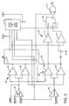
- Figure 1 is a schematic diagram of a preferred embodiment of the sputtering arc fault circuit breaker of the invention combined with, and sharing a sensing coil with, a ground fault detection circuit.
- Figure 2 is a schematic circuit diagram of an integrated circuit which forms part of the circuit of Figure 1.
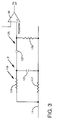
- Figure 3 is a schematic diagram illustrating a modification to a portion of the circuit breaker of figure 1.
- That circuit breaker includes a thermo-magnetic overcurrent trip mechanism and a ground fault detector mounted in side-by-side compartments within a molded housing.
- the ground fault detector includes a trip solenoid having a plunger which extends through the wall between the two compartments in the molded housing to actuate the thermo-magnetic trip mechanism to trip the circuit breaker in response to a ground fault.
- the circuit breaker 1 of the invention in its preferred embodiment, combines a sputtering arc detector 3 with a ground fault detector 5.
- the circuit breaker 1 protects an electric system 7 which includes a line conductor 9 and a neutral conductor 11 which provide electric power to a load 13.
- the circuit breaker 1 of the invention protects against sputtering arc faults 15 between the line conductor 9 and a neutral conductor 11, and line-to-ground faults 17 and neutral-to-ground faults 19.
- the sputtering arc fault 15 results when bared sections of the line and neutral conductors come in contact due to, for instance, worn or stripped insulation.
- Faults in the electrical system 7 are detected by the circuit breaker 1 by current sensors in the form of current transformers 21 and 23.
- These current transformers 21 and 23 are toroidal coils.
- the line conductor 9 and neutral conductor 11 are passed through the opening in the toroidal coil 21 to form the primary of that current transformer.
- the current transformer 23 has a single primary in the form of the neutral conductor 11 which passes through the opening of the toroidal coil.
- the second winding 25 of the current transformer 21 and the second winding 27 of the current transformer 23 are each connected to an integrated circuit 29.
- the current transformer 21 detects line-to-ground faults. With no line-to-ground fault on the electrical system 7, the currents through the line and neutral conductors 9, 11 which form the primaries of the transformer will be equal and opposite so that no current will be induced in the secondary winding 25. If the line conductor 9 is grounded, there will be a large current through this conductor and little or no current through the neutral conductor 11 so that a sizable current will be induced in the secondary winding 25.
- This signal is applied to the IC 29 through the NEGGFI and POSGFI inputs through a dc blocking capacitor 31 so that offsets in an op amp (to be described) in the IC are not applied to the current transformer 21.
- a resistor 33 critically dampens resonance caused by the series connected capacitor 31 and secondary winding 25 of the current transformer 21.
- a capacitor 35 across the IC inputs provides noise suppression.
- a feedback resistor 37 sets the gain for the op amp in the IC 29.
- the OR output on the IC 29 goes high to turn on an SCR 39.
- Turning on of the SCR 39 provides current for energization of a trip solenoid 41 with current drawn from the line and neutral conductors. This current is half wave rectified by the diode 43.
- the SCR 39 is protected from surges by the metal oxide varistor (MOV) 45 and from noise on the gate by capacitor 47.
- Energization of the trip solenoid 41 actuates the trip mechanism 49 as described in U.S. patent no. 4,081,852 to open contacts 51 at least in the line conductor 9, and preferably also in the neutral conductor 11.
- the diode 43 also provides DC power to a shunt regulator in the IC 29.
- the current drawn by the IC is insufficient to actuate the trip solenoid 41.
- the power supply for the IC 29 includes a filter capacitor 53, and a pair of resistors 55 and 57 which determine the voltage level of the supply. This DC power is provided to the VPOS input of the IC 29.
- the VNEG pin is connected to the ground for the neutral conductor.
- a bypass capacitor 59 assures that there is no ac on the VPOS input.
- another bypass capacitor 61 eliminates ac on the POSGFI input.
- the ground fault detector 5 is of the dormant oscillator type.
- the secondary winding 27 of the current transformer 23 is also connected to the output of the op amp in the IC 29 at pin GANP through a coupling capacitor 63.
- Neutral-to-ground faults couple the secondary windings 25 and 27 though the current transformers 21 and 23 to form a feedback loop around the IC 29 causing the op amp in the IC to oscillate.
- the frequency of this oscillation can be set by the selection of the value of the capacitor 63 and the capacitor 65 as well as the parameters of the current transformers 21 and 23. In the exemplary circuit breaker, this frequency is about 20 KHz.
- the current transformer 23 is also used to sense current for detecting sputtering arc faults.
- the rate of change of current signal, di/dt, needed for sputtering arc fault detection, is generated by providing a core in the current transformer 23 which does not saturate at the current level required to produce a trip.
- a suitable material for the core is powdered iron which has a low mu and a high flux saturation level. Such a core only affects the neutral ground detection by increasing the frequency of oscillation by a small amount.
- the di/dt signal produced on the secondary winding 27 of the current transformer 23 is bandwidth with limited by passing it through a low pass filter 67.
- This is a two pole low pass filter with the first pole formed by the capacitor 69 and resistor 71, and the second pole formed by the capacitor 73 and resistor 75.
- This low pass filter 67 in the exemplary circuit breaker has a half-power point at about 2 KHz.
- the di/dt signal can be used to provide an indication of overcurrent, line-to-neutral faults and sputtering arc faults.
- the parameters of the bandwidth limiting low pass filter 67 are selected to attenuate the spikes in the di/dt signal caused by a sputtering arc fault, and to regulate the relative sensitivity of the circuit to the sinusoidal currents of the overcurrent line-to-neutral faults and step functions of the sputtering arc faults.
- the present invention distinguishes sputtering arc faults from the in-rush currents caused by some appliances by counting the number of step functions detected within a predetermined time period.
- a capacitor 77 and resistor 79 set the selected time interval in the manner to be discussed below.
- FIG. 2 is a schematic circuit diagram of the IC 29.
- the chip 29 has a power supply 81 which is energized by the half wave rectified supply described above through the VPOS and VNEG pins.
- An op amp 83 amplifies the signal on the secondary of the current transformer 21 for application to a window comparator 85 comprising the comparators 87 and 89.
- the comparator 87 is biased by a reference voltage provided by the power supply 81 which is the positive threshold for detecting line-to-ground faults. Similarly, a negative threshold bias voltage is applied to the comparator 89.
- a bias voltage which is roughly the midpoint of the power supply voltage, is applied to the noninverting input of the op amp 83.
- a pull-up resistor 91 is connected between the outputs of the comparators 87 and 89 and VPOS.
- the output of these comparators is also connected to an inverting input of an OR circuit 93, the output of which is connected to the gate of the SCR 39 through the OR pin of the IC 29.
- the outputs of the comparators 87 and 89 are high so that the SCR 39 is not gated.
- the presence of a line-to-ground fault causes a signal generated on the secondary winding 25 of the current transformer 21 to exceed the thresholds applied to the comparators 87 and 89 during alternate half cycles of the load current.
- the second current transformer 23 is connected to the output of the op amp 83 through coupling capacitor 63 connected to the GANP pin of the IC 29. Any neutral-to-ground fault completes a feedback loop between the current transformer 23 connected to the output of the op amp 83 and the current transformer 21 connected to the input.
- the SCR 39 is gated through the OR 93.
- the current transformer 23 is also used to detect sputtering arc faults.
- the di/dt signal generated on the secondary winding 27, which is bandwidth limited by the low pass filter 67, is applied to a follower op amp 95 to a second window comparator 97 comprising the comparators 99 and 101.
- the comparators 99 and 101 compare the bandwidth limited di/dt signal to positive and negative thresholds set by the power supply 81.
- a pull-up resistor 103 connected to VPOS maintains a high logic signal at the outputs of the comparators 99 and 101 when the bandwidth limited di/dt signal is within the selected limits.
- a counter circuit 107 is provided on the output of the window comparator 97.
- the counter circuit 107 counts events in which the thresholds of the window comparator 97 are exceeded.
- the counting circuit 107 generates a trip signal on the occurrence of two such events within the selected time interval.
- the counter circuit 107 includes a D flip-flop 109.
- the flip-flop 109 is clocked by the output of the window comparator 97 through an inverter 111.
- the output of the window comparator 97 is also connected through a diode 113 to the inverting input of a comparator 115.
- This comparator 115 compares the output of the window comparator 97 with the positive threshold voltage generated by the power supply 81. Typically, this reference voltage is about three-quarters of the power supply voltage.
- the output of the comparator 115 is applied to the data input D of the flip-flop 109.
- the output of the flip-flop 109 which is not used in the circuit of Figure 2, goes to the logic value of the signal at the D terminal when a clock pulse is applied to the CLK input.
- the output of the flip-flop goes to the logical opposite of the signal applied to the D input when the flip-flop is clocked.
- The is connected to an inverting input of the OR 93.
- the inverting input of the comparator 115 is also connected through the RC pin of the IC 29 to the timing capacitor 77 (see figure 1).
- the other side of the capacitor 77 is connected to VPOS.
- the capacitor 77 is discharged by the shunt resistor 79. Therefore, the output of the comparator 115 is low.
- the flip-flop 109 is clocked by the leading edge of the pulse. As the D input was low at the time of the clock pulse, the output remains high, and no gate signal is applied to the SCR 39 through the OR 93.
- the capacitor 77 When the output of the window comparator 97 goes low, the capacitor 77 charges rapidly through the diode 113 to approximately VPOS. As the voltage on the noninverting input now exceeds the reference voltage, the output of the comparator 115 goes high. When the output of the window comparator 97 again goes high as the sputtering arc current reaches its peak magnitude, the capacitor 77 begins to discharge through the resistor 79.
- the values of these components are selected so that the voltage on the capacitor 77 remains above the reference voltage applied to the comparator 115 for the selected time interval. As mentioned, a suitable time interval is about one second.
- the D input of the flip-flop 109 will be high when the flip-flop is clocked, and hence the output will go low, causing the output of OR 93 to go high and gate the SCR 39 on to energize the trip solenoid 41.
- the sputtering arc fault detector 3' can be used independently of ground fault detection. In that case, the line conductor 9, rather than the neutral conductor 11, would pass through the core of a current transformer 23. Also, if the sputtering arc fault detection is to be provided independent of ground fault protection, the resistance of the neutral conductor could be used to detect sputtering arc faults.
- Figure 3 illustrates a portion of the circuit breaker 1 with the sputtering arc fault detector 3' so modified. As shown, the resistivity 117 of the neutral conductor 11 generates a voltage which is passed through a low pass filter 119 comprising the resistor 121 and capacitor 123.
- this low pass filter is then differentiated by a highpass filter 125 comprising a capacitor 127 and resistor 129.
- This combination of a low pass filter 119 followed by a high pass filter 125 produces the same bandwidth limited di/dt signal as the coil circuit of Figure 1, although at a significantly lower signal level.
- the bandwidth limited di/dt signal is applied to the noninverting input of the follower amplifier 95.
- the remainder of the sputtering arc detector circuit 3' is the same as shown in Figure 1.
- sputtering arc fault responsive circuit breaker 1 Other variations of the sputtering arc fault responsive circuit breaker 1 are possible. For instance, in place of the window comparators 85 and 97, single comparators can be preceded by full wave rectifiers. Also, other counter circuits to count the sputtering arc fault events could be used.
- the counter circuit is a monostable multi-vibrator, which would produce a constant width output pulse in response to the input from the level detection means.
- the constant width output pulses would be integrated and level detected to provide a trip on the second (or any other desired) pulse.
- the improved circuit breaker of the invention which trips on the second pulse generated by a sputtering arc fault, provides improved discrimination between arcing wiring and appliance turn-on.
- the improvement allows the sensing level to therefore be set much lower than otherwise would be possible.
Abstract
Description
- Commonly owned United States Patent Application Serial No. 765,759 entitled ELECTRONIC CIRCUIT BREAKER WITH PROTECTION AGAINST SPUTTERING ARC VAULTS AND GROUND FAULTS filed on September 26, 1991 in the names of Raymond W. Mackenzie and Joseph C. Engel.
- This invention relates to circuit breakers which respond to sputtering arc faults as well as bolted line-to-neutral and ground faults and, more particularly, to such a circuit breaker which discriminates between sputtering arc faults and in-rush currents generated by connecting certain loads to the protected conductors.
- Conventional residential circuit breakers have a thermal trip device which responds to persistent over-currents of moderate magnitude to provide a delayed trip, and a magnetic trip device which responds instantaneously to overcurrents of large magnitude. Thus, the fault current must reach a predetermined magnitude, for example ten times rated current for the instantaneous trip to occur, or the overcurrent must sustain a predetermined average value over a given time interval to implement the delayed trip. There is a type of fault, however, which may not produce either the peak magnitude required for the instantaneous magnetic trip or the sustained average overcurrent necessary for the delayed trip, yet may pose a fire hazard. This is the intermittent or sputtering arc-type of fault. Such a fault can occur, for instance, between two conductors that are in close proximity, but not touching so that an arc is struck between the conductors. This arc can produce a temperature high enough to melt the copper in the conductor. The melted droplets of copper can ignite flammable material in the vicinity. The resistance of the wire may be high enough to limit the peak current and the ac current cyclically passes through zero to extinguish the arc so that the average current is low. Thus, the conventional circuit breaker does not respond to the fault, although a hazard exists. This is especially true in the case of a stranded wire extension cord where an individual strand can be melted at a relatively low fault current.
- As sufficient voltage is required to strike the arc of a sputtering arc fault, this type of fault typically occurs near the peak of the ac voltage waveform thereby resulting in a step increase in current.
- The above cross-referenced patent application discloses a circuit breaker which takes advantage of this difference between the sinusoidal wave form of a line-to-neutral fault and the step wave form of a sputtering arc fault by monitoring the rate of change of current, di/dt, in the protected circuit. The di/dt signal is bandwidth limited. The selection of the band provides control of relative sensitivity of the circuit breaker to the sinusoidal overcurrents produced by overcurrent faults and step currents associated with sputtering arc-type faults. This circuit breaker includes a ground fault detector of the dormant oscillator type. The sputtering arc feature of the circuit breaker shares a common di/dt sensing coil on the neutral conductor with the ground fault detector.
- The arcing wave form characterized by fast turn on to high values of current produced by sputtering arc faults is also produced by some appliances, or groups of appliances switched on simultaneously. For instance, an iron which is turned on at the peak of the voltage wave form results in a step increase in current. Also, a television receiver with a transformerless power supply turned on at a peak of the ac wave form can result in a large in-rush current. Typically, the magnitude of the in-rush currents produced by these appliances is not as large as a sputtering arc fault and, thus, the circuit breaker of patent application serial no. 765,759 can avoid false trips by appropriate setting of the threshold level of the bandwidth limited di/dt signal.
- It would be desirable; however, to be able to discriminate between sputtering arc faults and in-rush currents produced by some appliances, so that the threshold of detection of the sputtering arc wave form could be lowered to provide greater protection for the conductors to which the circuit breaker is connected.
- This need and others are satisfied by the invention which recognizes that the sizeable in-rush currents generated by appliances are singular events, while a wiring failure will continue to produce high step currents until interrupted, or until there is no more available copper in the area of the failure. Hence, in accordance with the invention, protection is achieved, along with freedom from false tripping, by tripping only in response to multiple events detected within a short period of time. As high in-rush currents produced by appliances are singular events, the preferred embodiment of the invention trips upon detection of the second event. The selected time period must be long enough to include two events from a single wiring failure while not being so long as to be likely to include sequential turn-on of multiple loads. A period of about one second is preferred to suit both cases.
- A full understanding of the invention can be gained from the following description of the preferred embodiment when read in conjunction with the accompanying drawings in which:
- Figure 1 is a schematic diagram of a preferred embodiment of the sputtering arc fault circuit breaker of the invention combined with, and sharing a sensing coil with, a ground fault detection circuit.
- Figure 2 is a schematic circuit diagram of an integrated circuit which forms part of the circuit of Figure 1.
- Figure 3 is a schematic diagram illustrating a modification to a portion of the circuit breaker of figure 1.
- The invention will be described as applied to a conventional residential circuit breaker such as that described in U.S. patent no. 4,081,852 which is herein incorporated by reference. That circuit breaker includes a thermo-magnetic overcurrent trip mechanism and a ground fault detector mounted in side-by-side compartments within a molded housing. The ground fault detector includes a trip solenoid having a plunger which extends through the wall between the two compartments in the molded housing to actuate the thermo-magnetic trip mechanism to trip the circuit breaker in response to a ground fault.
- As shown in Figure 1, the
circuit breaker 1 of the invention, in its preferred embodiment, combines a sputteringarc detector 3 with aground fault detector 5. Thecircuit breaker 1 protects anelectric system 7 which includes aline conductor 9 and aneutral conductor 11 which provide electric power to aload 13. In addition to protecting against typical overcurrents drawn by theload 13 and bolted line-to-neutral faults, thecircuit breaker 1 of the invention protects against sputteringarc faults 15 between theline conductor 9 and aneutral conductor 11, and line-to-ground faults 17 and neutral-to-ground faults 19. As discussed above, the sputteringarc fault 15 results when bared sections of the line and neutral conductors come in contact due to, for instance, worn or stripped insulation. - Faults in the
electrical system 7 are detected by thecircuit breaker 1 by current sensors in the form ofcurrent transformers current transformers line conductor 9 andneutral conductor 11 are passed through the opening in thetoroidal coil 21 to form the primary of that current transformer. Thecurrent transformer 23 has a single primary in the form of theneutral conductor 11 which passes through the opening of the toroidal coil. The second winding 25 of thecurrent transformer 21 and the second winding 27 of thecurrent transformer 23 are each connected to an integratedcircuit 29. - The current transformer 21 detects line-to-ground faults. With no line-to-ground fault on the
electrical system 7, the currents through the line andneutral conductors secondary winding 25. If theline conductor 9 is grounded, there will be a large current through this conductor and little or no current through theneutral conductor 11 so that a sizable current will be induced in thesecondary winding 25. This signal is applied to theIC 29 through the NEGGFI and POSGFI inputs through adc blocking capacitor 31 so that offsets in an op amp (to be described) in the IC are not applied to thecurrent transformer 21. Aresistor 33 critically dampens resonance caused by the series connectedcapacitor 31 andsecondary winding 25 of thecurrent transformer 21. Acapacitor 35 across the IC inputs provides noise suppression. Afeedback resistor 37 sets the gain for the op amp in theIC 29. - As will be discussed in more detail below, if the magnitude of the current in the
secondary winding 25 of thecurrent transformer 21 exceeds a threshold selected to detect a line-to-ground fault, the OR output on theIC 29 goes high to turn on anSCR 39. Turning on of theSCR 39 provides current for energization of atrip solenoid 41 with current drawn from the line and neutral conductors. This current is half wave rectified by thediode 43. The SCR 39 is protected from surges by the metal oxide varistor (MOV) 45 and from noise on the gate bycapacitor 47. Energization of thetrip solenoid 41 actuates thetrip mechanism 49 as described in U.S. patent no. 4,081,852 to opencontacts 51 at least in theline conductor 9, and preferably also in theneutral conductor 11. - The
diode 43 also provides DC power to a shunt regulator in theIC 29. The current drawn by the IC is insufficient to actuate thetrip solenoid 41. The power supply for theIC 29 includes afilter capacitor 53, and a pair ofresistors IC 29. The VNEG pin is connected to the ground for the neutral conductor. Abypass capacitor 59 assures that there is no ac on the VPOS input. Similarly, anotherbypass capacitor 61 eliminates ac on the POSGFI input. - The
ground fault detector 5 is of the dormant oscillator type. The secondary winding 27 of thecurrent transformer 23 is also connected to the output of the op amp in theIC 29 at pin GANP through acoupling capacitor 63. Neutral-to-ground faults couple thesecondary windings current transformers IC 29 causing the op amp in the IC to oscillate. The frequency of this oscillation can be set by the selection of the value of thecapacitor 63 and thecapacitor 65 as well as the parameters of thecurrent transformers SCR 39 is fired to trip the circuit breaker. - In accordance with the invention, the
current transformer 23 is also used to sense current for detecting sputtering arc faults. The rate of change of current signal, di/dt, needed for sputtering arc fault detection, is generated by providing a core in thecurrent transformer 23 which does not saturate at the current level required to produce a trip. A suitable material for the core is powdered iron which has a low mu and a high flux saturation level. Such a core only affects the neutral ground detection by increasing the frequency of oscillation by a small amount. - The di/dt signal produced on the secondary winding 27 of the
current transformer 23 is bandwidth with limited by passing it through alow pass filter 67. This is a two pole low pass filter with the first pole formed by thecapacitor 69 andresistor 71, and the second pole formed by thecapacitor 73 andresistor 75. Thislow pass filter 67 in the exemplary circuit breaker has a half-power point at about 2 KHz. As discussed in the above referenced patent application, the di/dt signal can be used to provide an indication of overcurrent, line-to-neutral faults and sputtering arc faults. The parameters of the bandwidth limitinglow pass filter 67 are selected to attenuate the spikes in the di/dt signal caused by a sputtering arc fault, and to regulate the relative sensitivity of the circuit to the sinusoidal currents of the overcurrent line-to-neutral faults and step functions of the sputtering arc faults. As also discussed above, the present invention distinguishes sputtering arc faults from the in-rush currents caused by some appliances by counting the number of step functions detected within a predetermined time period. Acapacitor 77 andresistor 79 set the selected time interval in the manner to be discussed below. - Figure 2 is a schematic circuit diagram of the
IC 29. Thechip 29 has apower supply 81 which is energized by the half wave rectified supply described above through the VPOS and VNEG pins. Anop amp 83 amplifies the signal on the secondary of thecurrent transformer 21 for application to awindow comparator 85 comprising thecomparators comparator 87 is biased by a reference voltage provided by thepower supply 81 which is the positive threshold for detecting line-to-ground faults. Similarly, a negative threshold bias voltage is applied to thecomparator 89. A bias voltage, which is roughly the midpoint of the power supply voltage, is applied to the noninverting input of theop amp 83. A pull-upresistor 91 is connected between the outputs of thecomparators OR circuit 93, the output of which is connected to the gate of theSCR 39 through the OR pin of theIC 29. Normally, the outputs of thecomparators SCR 39 is not gated. The presence of a line-to-ground fault causes a signal generated on the secondary winding 25 of thecurrent transformer 21 to exceed the thresholds applied to thecomparators comparator 87 to go low so that the output of theOR circuit 93 goes high to gate theSCR 39 and energize thetrip solenoid 41. On negative half cycles, thecomparator 89 turns on theSCR 39. - As previously discussed, for neutral-to-ground faults, the second
current transformer 23 is connected to the output of theop amp 83 throughcoupling capacitor 63 connected to the GANP pin of theIC 29. Any neutral-to-ground fault completes a feedback loop between thecurrent transformer 23 connected to the output of theop amp 83 and thecurrent transformer 21 connected to the input. When the magnitude of this oscillation exceeds the thresholds of thewindow comparator 85, theSCR 39 is gated through theOR 93. - As mentioned, the
current transformer 23 is also used to detect sputtering arc faults. The di/dt signal generated on the secondary winding 27, which is bandwidth limited by thelow pass filter 67, is applied to afollower op amp 95 to asecond window comparator 97 comprising thecomparators comparators power supply 81. A pull-upresistor 103 connected to VPOS maintains a high logic signal at the outputs of thecomparators window comparator 97 goes low. As certain appliances can generate a similar wave form, albeit typically of lower magnitude, acounter circuit 107 is provided on the output of thewindow comparator 97. Thecounter circuit 107 counts events in which the thresholds of thewindow comparator 97 are exceeded. In the preferred embodiment of the invention, thecounting circuit 107 generates a trip signal on the occurrence of two such events within the selected time interval. - The
counter circuit 107 includes a D flip-flop 109. The flip-flop 109 is clocked by the output of thewindow comparator 97 through aninverter 111. The output of thewindow comparator 97 is also connected through a diode 113 to the inverting input of acomparator 115. Thiscomparator 115 compares the output of thewindow comparator 97 with the positive threshold voltage generated by thepower supply 81. Typically, this reference voltage is about three-quarters of the power supply voltage. The output of thecomparator 115 is applied to the data input D of the flip-flop 109. Theoutput of the flip-
flop 109, which is not used in the circuit of Figure 2, goes to the logic value of the signal at the D terminal when a clock pulse is applied to the CLK input. Thus, theoutput of the flip-flop goes to the logical opposite of the signal applied to the D input when the flip-flop is clocked. The is connected to an inverting input of the
OR 93. - The inverting input of the
comparator 115 is also connected through the RC pin of theIC 29 to the timing capacitor 77 (see figure 1). The other side of thecapacitor 77 is connected to VPOS. Under normal circumstances, thecapacitor 77 is discharged by theshunt resistor 79. Therefore, the output of thecomparator 115 is low. When the output of thewindow comparator 97 goes low for the first time, indicating a sputtering arc fault event, the flip-flop 109 is clocked by the leading edge of the pulse. As the D input was low at the time of the clock pulse, theoutput remains high, and no gate signal is applied to the
SCR 39 through theOR 93. When the output of thewindow comparator 97 goes low, thecapacitor 77 charges rapidly through the diode 113 to approximately VPOS. As the voltage on the noninverting input now exceeds the reference voltage, the output of thecomparator 115 goes high. When the output of thewindow comparator 97 again goes high as the sputtering arc current reaches its peak magnitude, thecapacitor 77 begins to discharge through theresistor 79. The values of these components are selected so that the voltage on thecapacitor 77 remains above the reference voltage applied to thecomparator 115 for the selected time interval. As mentioned, a suitable time interval is about one second. If the output of thewindow comparator 97 goes low before the timer has timed out, which is indicative of a sputtering arc fault, the D input of the flip-flop 109 will be high when the flip-flop is clocked, and hence theoutput will go low, causing the output of OR 93 to go high and gate the
SCR 39 on to energize thetrip solenoid 41. - The sputtering arc fault detector 3' can be used independently of ground fault detection. In that case, the
line conductor 9, rather than theneutral conductor 11, would pass through the core of acurrent transformer 23. Also, if the sputtering arc fault detection is to be provided independent of ground fault protection, the resistance of the neutral conductor could be used to detect sputtering arc faults. Figure 3 illustrates a portion of thecircuit breaker 1 with the sputtering arc fault detector 3' so modified. As shown, theresistivity 117 of theneutral conductor 11 generates a voltage which is passed through alow pass filter 119 comprising theresistor 121 andcapacitor 123. The output of this low pass filter is then differentiated by ahighpass filter 125 comprising acapacitor 127 andresistor 129. This combination of alow pass filter 119 followed by ahigh pass filter 125 produces the same bandwidth limited di/dt signal as the coil circuit of Figure 1, although at a significantly lower signal level. As in the case of the circuit breaker of Figure 1, the bandwidth limited di/dt signal is applied to the noninverting input of thefollower amplifier 95. The remainder of the sputtering arc detector circuit 3' is the same as shown in Figure 1. - Other variations of the sputtering arc fault
responsive circuit breaker 1 are possible. For instance, in place of thewindow comparators - Another possibility for the counter circuit is a monostable multi-vibrator, which would produce a constant width output pulse in response to the input from the level detection means. The constant width output pulses would be integrated and level detected to provide a trip on the second (or any other desired) pulse.
- The improved circuit breaker of the invention, which trips on the second pulse generated by a sputtering arc fault, provides improved discrimination between arcing wiring and appliance turn-on. The improvement allows the sensing level to therefore be set much lower than otherwise would be possible.
- While specific embodiments of the invention have been described in detail, it will be appreciated by those skilled in the art that various modifications and alternatives to those details could be developed in light of the overall teachings of the disclosure. Accordingly, the particular arrangements disclosed are meant to be illustrative only and not limiting as to the scope of the invention which is to be given the full breadth of the appended claims and any and all equivalents thereof.
Claims (11)
- A circuit breaker for protecting an ac electrical system from sputtering arc faults, characterized by a current sensing device sensing current flowing in said electrical system, an event generating device responsive to said current sensing means generating a bandwidth limited rate of change of current (di/dt) signal, a trip signal device generating a trip signal in response to a plurality of event signals within a preselected time interval; and interrupting device responsive to said trip signal interrupting current flowing in said electrical system.
- The circuit breaker of claim 1 wherein said trip signal device generates the trip signal in response to two event signals within said preselected time interval.
- The circuit breaker of claim 2 wherein said trip signal device generates a trip signal in response to two event signals within about a one second time interval.
- The circuit breaker of claim 1 wherein said trip signal device comprises a counter counting said event signals.
- The circuit breaker of claim 1 wherein said event generating device includes a bandwidth device comparing said bandwidth limited di/dt signal to threshold values and generating the event signal when said threshold values are exceeded.
- The circuit breaker of claim 5 wherein said trip signal device comprises a counter counting said event signals and a timer timing the selected interval.
- The circuit breaker of claim 6 wherein said counter generates said trip signal when two event signals are generated within said predetermined time interval.
- The circuit breaker of claim 7 wherein said timer generates a timing interval of approximately one second.
- The circuit breaker of claim 5 wherein said current sensing device comprises a signal generating device generating a di/dt signal and said event generating device generating said bandwidth limited di/dt signal comprises a two pole, low pass filter.
- The circuit breaker of claim 5 wherein said current sensing device includes a resistivity device connected across a portion of a conductor within said circuit breaker carrying current of said electrical system to utilize resistivity of said portion of said conductor to detect current, and a bandwidth limited signal generating device for generating said bandwidth limited di/dt signal from the current detected.
- The circuit breaker of claim 10 wherein said bandwidth limited signal genrating device comprises a low pass filter followed by a high pass filter.
Applications Claiming Priority (2)
| Application Number | Priority Date | Filing Date | Title |
|---|---|---|---|
| US2343593A | 1993-02-26 | 1993-02-26 | |
| US23435 | 1993-02-26 |
Publications (2)
| Publication Number | Publication Date |
|---|---|
| EP0615327A2 true EP0615327A2 (en) | 1994-09-14 |
| EP0615327A3 EP0615327A3 (en) | 1994-09-21 |
Family
ID=21815079
Family Applications (1)
| Application Number | Title | Priority Date | Filing Date |
|---|---|---|---|
| EP19940301370 Ceased EP0615327A3 (en) | 1993-02-26 | 1994-02-25 | Circuit breaker responsive to repeated in-rush currents produced by a sputtering arc fault. |
Country Status (5)
| Country | Link |
|---|---|
| US (2) | US5940256A (en) |
| EP (1) | EP0615327A3 (en) |
| JP (1) | JP3589692B2 (en) |
| CA (1) | CA2116496A1 (en) |
| ZA (1) | ZA941138B (en) |
Cited By (31)
| Publication number | Priority date | Publication date | Assignee | Title |
|---|---|---|---|---|
| EP0649206A1 (en) * | 1993-09-15 | 1995-04-19 | Eaton Corporation | Ground fault circuit interrupter with immunity to wide band noise |
| EP0712193A1 (en) * | 1994-11-08 | 1996-05-15 | Eaton Corporation | Circuit breaker using bimetal of thermal-magnetic trip to sense current |
| EP0748021A1 (en) * | 1995-06-06 | 1996-12-11 | Eaton Corporation | Low cost apparatus for detecting arcing faults and circuit breaker incorporating same |
| WO1997030501A1 (en) * | 1996-02-13 | 1997-08-21 | Square D Company | Arcing fault detection system |
| EP0802602A2 (en) * | 1996-04-17 | 1997-10-22 | Eaton Corporation | Apparatus for detecting and responding to series arcs in AC electrical systems |
| EP0813281A2 (en) * | 1996-06-10 | 1997-12-17 | Eaton Corporation | Apparatus for envelope detection of low current arcs |
| US5825598A (en) * | 1997-02-11 | 1998-10-20 | Square D Company | Arcing fault detection system installed in a panelboard |
| US5834940A (en) * | 1996-09-24 | 1998-11-10 | Brooks; Stanley J. | Arcing fault detector testing and demonstration system |
| US5839092A (en) | 1997-03-26 | 1998-11-17 | Square D Company | Arcing fault detection system using fluctuations in current peaks and waveforms |
| US5847913A (en) | 1997-02-21 | 1998-12-08 | Square D Company | Trip indicators for circuit protection devices |
| US5946179A (en) | 1997-03-25 | 1999-08-31 | Square D Company | Electronically controlled circuit breaker with integrated latch tripping |
| DE19830643A1 (en) * | 1998-07-09 | 2000-01-13 | Bernd Rohrmann | Arcing protection arrangement protecting low voltage networks against arcing enables detection of arcing and initiates measures to provide warning or switch off appropriate circuits |
| US6034611A (en) | 1997-02-04 | 2000-03-07 | Square D Company | Electrical isolation device |
| EP1005129A2 (en) * | 1998-11-23 | 2000-05-31 | Siemens Energy & Automation, Inc. | Arc fault detector method |
| EP1005128A2 (en) * | 1998-11-23 | 2000-05-31 | Siemens Energy & Automation, Inc. | Arc fault detector apparatus, means and system |
| US6242993B1 (en) | 1995-03-13 | 2001-06-05 | Square D Company | Apparatus for use in arcing fault detection systems |
| US6313642B1 (en) | 1995-03-13 | 2001-11-06 | Square D Company | Apparatus and method for testing an arcing fault detection system |
| US6377427B1 (en) | 1995-03-13 | 2002-04-23 | Square D Company | Arc fault protected electrical receptacle |
| US6452767B1 (en) | 1995-03-13 | 2002-09-17 | Square D Company | Arcing fault detection system for a secondary line of a current transformer |
| US6477021B1 (en) | 1998-02-19 | 2002-11-05 | Square D Company | Blocking/inhibiting operation in an arc fault detection system |
| US6532424B1 (en) | 1995-03-13 | 2003-03-11 | Square D Company | Electrical fault detection circuit with dual-mode power supply |
| US6567250B1 (en) | 1998-02-19 | 2003-05-20 | Square D Company | Arc fault protected device |
| US6621669B1 (en) | 1998-02-19 | 2003-09-16 | Square D Company | Arc fault receptacle with a feed-through connection |
| US6625550B1 (en) | 1998-02-19 | 2003-09-23 | Square D Company | Arc fault detection for aircraft |
| EP1400187A1 (en) * | 2002-09-18 | 2004-03-24 | Ok-Nam Cho | Circuit for controlling the temperature of a hair iron |
| US6782329B2 (en) | 1998-02-19 | 2004-08-24 | Square D Company | Detection of arcing faults using bifurcated wiring system |
| DE10029235B4 (en) * | 1999-06-14 | 2016-09-15 | General Electric Company | Method for detecting systematic error conditions in a smart electronic device |
| CN108808621A (en) * | 2017-05-05 | 2018-11-13 | 韦伯-斯蒂芬产品有限公司 | Wireless control and status monitoring for the electric oven with current protecting circuit |
| US10524312B2 (en) | 2016-07-01 | 2019-12-31 | Weber-Stephen Products Llc | Electric grill with current protection circuitry |
| US11454677B2 (en) | 2016-07-01 | 2022-09-27 | Weber-Stephen Products Llc | Wireless control and status monitoring for electric grill with current protection circuitry |
| US11703928B2 (en) | 2016-07-01 | 2023-07-18 | Weber-Stephen Products Llc | Digital power supply with wireless monitoring and control |
Families Citing this family (67)
| Publication number | Priority date | Publication date | Assignee | Title |
|---|---|---|---|---|
| US6313641B1 (en) | 1995-03-13 | 2001-11-06 | Square D Company | Method and system for detecting arcing faults and testing such system |
| WO1998058432A1 (en) * | 1997-06-17 | 1998-12-23 | Dipl.-Ing. Walther Bender Gmbh & Co. Kg | Method and device for monitoring insulation and fault current in an electrical alternating current network |
| US6275044B1 (en) | 1998-07-15 | 2001-08-14 | Square D Company | Arcing fault detection system |
| US7400477B2 (en) | 1998-08-24 | 2008-07-15 | Leviton Manufacturing Co., Inc. | Method of distribution of a circuit interrupting device with reset lockout and reverse wiring protection |
| US6128170A (en) * | 1998-11-19 | 2000-10-03 | General Electric Company | Analog based first and fast second pulse removal system |
| CA2337446A1 (en) | 2000-02-17 | 2001-08-17 | Bruce F. Macbeth | Arc fault circuit interrupter recognizing arc noise burst patterns |
| KR100423886B1 (en) | 2000-05-12 | 2004-03-24 | 휴먼엘텍 주식회사 | Arc fault circuit interrupter and circuit breaker having the same |
| US6532140B1 (en) | 2000-06-02 | 2003-03-11 | Raytheon Company | Arc-fault detecting circuit breaker system |
| US7035066B2 (en) | 2000-06-02 | 2006-04-25 | Raytheon Company | Arc-default detecting circuit breaker system |
| EP1303897A1 (en) * | 2000-06-26 | 2003-04-23 | Premier Aviation, Inc. | Method and apparatus for detecting electrical faults and isolating power source from the electrical faults |
| US6678137B1 (en) * | 2000-08-04 | 2004-01-13 | General Electric Company | Temperature compensation circuit for an arc fault current interrupting circuit breaker |
| AU2001271101A1 (en) | 2000-08-22 | 2002-03-04 | Human El-Tech, Inc | Overload circuit interrupter capable of electrical tripping and circuit breaker with the same |
| US6642832B2 (en) * | 2000-12-08 | 2003-11-04 | Texas Instruments Incorporated | ARC responsive thermal circuit breaker |
| US6717786B2 (en) | 2001-10-30 | 2004-04-06 | The Boeing Company | Automatic voltage source selector for circuit breakers utilizing electronics |
| US6671150B2 (en) | 2001-11-07 | 2003-12-30 | Eaton Corporation | Circuit breaker for detecting an excessive voltage and tripping responsive thereto |
| KR100524540B1 (en) * | 2002-06-22 | 2005-10-31 | 서창전기통신 주식회사 | Device for Detecting Arc Fault |
| US7003435B2 (en) * | 2002-10-03 | 2006-02-21 | Leviton Manufacturing Co., Inc. | Arc fault detector with circuit interrupter |
| KR100487929B1 (en) * | 2002-11-15 | 2005-05-27 | 서창전기통신 주식회사 | Device for Detecting Arc Fault |
| US7492562B2 (en) * | 2003-09-10 | 2009-02-17 | Siemens Energy & Automation, Inc. | AFCI temperature compensated current sensor |
| US7180211B2 (en) * | 2003-09-22 | 2007-02-20 | Micro Technology, Inc. | Temperature sensor |
| US7149066B2 (en) * | 2003-10-07 | 2006-12-12 | Eaton Corporation | Fault detector for two line power distribution system and protection apparatus incorporating the same |
| US6972572B2 (en) | 2003-12-22 | 2005-12-06 | Leviton Manufacturing Co., Inc. | Arc fault detector |
| US7460346B2 (en) * | 2005-03-24 | 2008-12-02 | Honeywell International Inc. | Arc fault detection and confirmation using voltage and current analysis |
| CN1955725B (en) | 2005-10-27 | 2010-12-15 | Ge医疗系统环球技术有限公司 | X-ray ct system |
| US20070159758A1 (en) * | 2006-01-09 | 2007-07-12 | Ceramate Technical Co., Ltd. | Protective circuit for thunderbolt abrupt waves |
| US7441173B2 (en) * | 2006-02-16 | 2008-10-21 | Siemens Energy & Automation, Inc. | Systems, devices, and methods for arc fault detection |
| US20070208520A1 (en) * | 2006-03-01 | 2007-09-06 | Siemens Energy & Automation, Inc. | Systems, devices, and methods for arc fault management |
| US7573112B2 (en) * | 2006-04-14 | 2009-08-11 | Allegro Microsystems, Inc. | Methods and apparatus for sensor having capacitor on chip |
| US7687882B2 (en) * | 2006-04-14 | 2010-03-30 | Allegro Microsystems, Inc. | Methods and apparatus for integrated circuit having multiple dies with at least one on chip capacitor |
| US7499250B2 (en) * | 2006-04-19 | 2009-03-03 | Siemens Energy & Automation, Inc. | Systems, devices, and methods for temperature compensation in arc fault detection systems |
| WO2008005928A2 (en) * | 2006-06-30 | 2008-01-10 | Leviton Manufacturing Company, Inc. | Circuit interrupter with live ground detector |
| US20080013298A1 (en) | 2006-07-14 | 2008-01-17 | Nirmal Sharma | Methods and apparatus for passive attachment of components for integrated circuits |
| US7463465B2 (en) * | 2006-12-28 | 2008-12-09 | General Electric Company | Series arc fault current interrupters and methods |
| DE102007013712A1 (en) * | 2007-03-22 | 2008-09-25 | Ellenberger & Poensgen Gmbh | Method and device for evaluating rapid changes in current |
| US7746605B2 (en) * | 2007-08-07 | 2010-06-29 | Eaton Corporation | Arc fault circuit interrupter and method of detecting and interrupting a resistive series arc of a power circuit |
| KR100883396B1 (en) * | 2007-09-06 | 2009-02-11 | 주식회사 케이이피 | Apparetus for detecting true arc of home cabinet panel branch circuit |
| KR100952222B1 (en) * | 2007-12-18 | 2010-04-09 | 주식회사 에너테크 | A cutoff apparatus for arc-current and method thereof |
| WO2009097469A1 (en) | 2008-01-29 | 2009-08-06 | Leviton Manufacturing Co., Inc. | Self testing fault circuit interrupter apparatus and method |
| US7924537B2 (en) * | 2008-07-09 | 2011-04-12 | Leviton Manufacturing Company, Inc. | Miswiring circuit coupled to an electrical fault interrupter |
| US8093670B2 (en) * | 2008-07-24 | 2012-01-10 | Allegro Microsystems, Inc. | Methods and apparatus for integrated circuit having on chip capacitor with eddy current reductions |
| US7791846B2 (en) * | 2008-07-30 | 2010-09-07 | General Electric Company | Arc flash detection system, apparatus and method |
| US20100052424A1 (en) * | 2008-08-26 | 2010-03-04 | Taylor William P | Methods and apparatus for integrated circuit having integrated energy storage device |
| US8526143B2 (en) * | 2009-05-14 | 2013-09-03 | Siemens Industry, Inc. | Methods and appraratus for ground fault circuit interrupt detection using a single transformer |
| US8908338B2 (en) * | 2009-06-03 | 2014-12-09 | Siemens Industry, Inc. | Methods and apparatus for multi-frequency ground fault circuit interrupt grounded neutral fault detection |
| JP5351062B2 (en) * | 2010-01-13 | 2013-11-27 | 三菱電機株式会社 | Circuit breaker |
| JP5613551B2 (en) * | 2010-12-21 | 2014-10-22 | 旭東電気株式会社 | Switch |
| US8599523B1 (en) | 2011-07-29 | 2013-12-03 | Leviton Manufacturing Company, Inc. | Arc fault circuit interrupter |
| CN102364763B (en) * | 2011-08-09 | 2013-06-26 | 刘睿刚 | Leakage protection plug |
| CN102354867B (en) * | 2011-08-09 | 2013-07-24 | 刘睿刚 | Electric leakage protection plug |
| CN102354866B (en) * | 2011-08-09 | 2013-04-17 | 刘睿刚 | Electricity leakage protection plug |
| CN102364761A (en) * | 2011-08-09 | 2012-02-29 | 刘睿刚 | Leakage protection plug |
| US20130054144A1 (en) * | 2011-08-23 | 2013-02-28 | General Electric Company | Distribution Feeder Outage Reduction |
| US8547673B2 (en) | 2011-11-30 | 2013-10-01 | Eaton Corporation | Electrical switching apparatus with overvoltage protection |
| US8629539B2 (en) | 2012-01-16 | 2014-01-14 | Allegro Microsystems, Llc | Methods and apparatus for magnetic sensor having non-conductive die paddle |
| US10234513B2 (en) | 2012-03-20 | 2019-03-19 | Allegro Microsystems, Llc | Magnetic field sensor integrated circuit with integral ferromagnetic material |
| US9812588B2 (en) | 2012-03-20 | 2017-11-07 | Allegro Microsystems, Llc | Magnetic field sensor integrated circuit with integral ferromagnetic material |
| US9666788B2 (en) | 2012-03-20 | 2017-05-30 | Allegro Microsystems, Llc | Integrated circuit package having a split lead frame |
| US9494660B2 (en) | 2012-03-20 | 2016-11-15 | Allegro Microsystems, Llc | Integrated circuit package having a split lead frame |
| US8749929B1 (en) * | 2012-12-17 | 2014-06-10 | Eaton Corporation | Circuit interrupter providing ground fault protection and system including the same |
| US9411025B2 (en) | 2013-04-26 | 2016-08-09 | Allegro Microsystems, Llc | Integrated circuit package having a split lead frame and a magnet |
| US9401595B2 (en) * | 2013-05-23 | 2016-07-26 | Jianyou GE | Electricity leakage warning |
| US9759758B2 (en) | 2014-04-25 | 2017-09-12 | Leviton Manufacturing Co., Inc. | Ground fault detector |
| US10411498B2 (en) | 2015-10-21 | 2019-09-10 | Allegro Microsystems, Llc | Apparatus and methods for extending sensor integrated circuit operation through a power disturbance |
| CA3026852A1 (en) * | 2018-02-07 | 2019-08-07 | Goodrich Corporation | Fault interrupt module |
| US10978897B2 (en) | 2018-04-02 | 2021-04-13 | Allegro Microsystems, Llc | Systems and methods for suppressing undesirable voltage supply artifacts |
| CN114128070A (en) * | 2019-07-17 | 2022-03-01 | 松下知识产权经营株式会社 | Power cut-off device |
| US10991644B2 (en) | 2019-08-22 | 2021-04-27 | Allegro Microsystems, Llc | Integrated circuit package having a low profile |
Citations (5)
| Publication number | Priority date | Publication date | Assignee | Title |
|---|---|---|---|---|
| US3801899A (en) * | 1973-03-26 | 1974-04-02 | Gen Electric | Means for detecting the inception of corona discharges within induction apparatus |
| EP0094871A1 (en) * | 1982-05-19 | 1983-11-23 | Merlin Gerin | Electronic arc detection relay |
| EP0313422A1 (en) * | 1987-10-09 | 1989-04-26 | Merlin Gerin | Static tripping device for a circuit breaker in a cast case |
| GB2229053A (en) * | 1989-03-07 | 1990-09-12 | Plessey Co Plc | Protection against arcing in cables |
| EP0510795A2 (en) * | 1991-03-28 | 1992-10-28 | Eaton Corporation | Timing window arc detection |
Family Cites Families (15)
| Publication number | Priority date | Publication date | Assignee | Title |
|---|---|---|---|---|
| US30678A (en) * | 1860-11-20 | Hose-couplietg | ||
| US3673455A (en) * | 1970-11-18 | 1972-06-27 | Gen Electric | High speed sensor for initiating circuit breaker tripping |
| US3852642A (en) * | 1972-11-01 | 1974-12-03 | Westinghouse Electric Corp | Sensing amplifier and trip circuit particularly for ground fault circuit interrupter |
| US3858130A (en) * | 1973-12-04 | 1974-12-31 | Westinghouse Electric Corp | Ground fault circuit breaker with cold temperature bimetal constriction |
| US4081852A (en) * | 1974-10-03 | 1978-03-28 | Westinghouse Electric Corporation | Ground fault circuit breaker |
| USRE30678E (en) | 1976-03-26 | 1981-07-14 | Eaton Corp. | Dormant oscillator ground to neutral protection for ground fault interrupters |
| US4081185A (en) * | 1976-07-23 | 1978-03-28 | Dresser Industries, Inc. | Oil well swab cup |
| US4376243A (en) * | 1981-01-26 | 1983-03-08 | General Motors Corporation | Arc detector for electric rod furnace |
| US4466071A (en) * | 1981-09-28 | 1984-08-14 | Texas A&M University System | High impedance fault detection apparatus and method |
| US4402030A (en) * | 1982-02-19 | 1983-08-30 | Champion Spark Plug Company | Electrostatic voltage control circuit |
| US4897756A (en) * | 1987-01-30 | 1990-01-30 | Square D Company | Add-on ground fault module |
| US4949214A (en) * | 1989-08-28 | 1990-08-14 | Spencer George A | Trip delay override for electrical circuit breakers |
| US5224006A (en) * | 1991-09-26 | 1993-06-29 | Westinghouse Electric Corp. | Electronic circuit breaker with protection against sputtering arc faults and ground faults |
| US5280404A (en) * | 1992-05-15 | 1994-01-18 | Bio-Rad Laboratories, Inc. | Arc detection system |
| US5519561A (en) * | 1994-11-08 | 1996-05-21 | Eaton Corporation | Circuit breaker using bimetal of thermal-magnetic trip to sense current |
-
1994
- 1994-02-18 ZA ZA941138A patent/ZA941138B/en unknown
- 1994-02-25 EP EP19940301370 patent/EP0615327A3/en not_active Ceased
- 1994-02-25 JP JP05303694A patent/JP3589692B2/en not_active Expired - Fee Related
- 1994-02-25 CA CA002116496A patent/CA2116496A1/en not_active Abandoned
- 1994-11-09 US US08/336,721 patent/US5940256A/en not_active Expired - Lifetime
-
1999
- 1999-06-03 US US09/324,560 patent/US6057997A/en not_active Expired - Lifetime
Patent Citations (5)
| Publication number | Priority date | Publication date | Assignee | Title |
|---|---|---|---|---|
| US3801899A (en) * | 1973-03-26 | 1974-04-02 | Gen Electric | Means for detecting the inception of corona discharges within induction apparatus |
| EP0094871A1 (en) * | 1982-05-19 | 1983-11-23 | Merlin Gerin | Electronic arc detection relay |
| EP0313422A1 (en) * | 1987-10-09 | 1989-04-26 | Merlin Gerin | Static tripping device for a circuit breaker in a cast case |
| GB2229053A (en) * | 1989-03-07 | 1990-09-12 | Plessey Co Plc | Protection against arcing in cables |
| EP0510795A2 (en) * | 1991-03-28 | 1992-10-28 | Eaton Corporation | Timing window arc detection |
Cited By (41)
| Publication number | Priority date | Publication date | Assignee | Title |
|---|---|---|---|---|
| AU678036B2 (en) * | 1993-09-15 | 1997-05-15 | Eaton Corporation | Ground fault circuit interrupter with immunity to wide band noise |
| EP0649206A1 (en) * | 1993-09-15 | 1995-04-19 | Eaton Corporation | Ground fault circuit interrupter with immunity to wide band noise |
| EP0712193A1 (en) * | 1994-11-08 | 1996-05-15 | Eaton Corporation | Circuit breaker using bimetal of thermal-magnetic trip to sense current |
| US6242993B1 (en) | 1995-03-13 | 2001-06-05 | Square D Company | Apparatus for use in arcing fault detection systems |
| US6313642B1 (en) | 1995-03-13 | 2001-11-06 | Square D Company | Apparatus and method for testing an arcing fault detection system |
| US6377427B1 (en) | 1995-03-13 | 2002-04-23 | Square D Company | Arc fault protected electrical receptacle |
| US6452767B1 (en) | 1995-03-13 | 2002-09-17 | Square D Company | Arcing fault detection system for a secondary line of a current transformer |
| US6195241B1 (en) | 1995-03-13 | 2001-02-27 | Squares D Company | Arcing fault detection system |
| US6532424B1 (en) | 1995-03-13 | 2003-03-11 | Square D Company | Electrical fault detection circuit with dual-mode power supply |
| US6591482B1 (en) | 1995-03-13 | 2003-07-15 | Square D Company | Assembly methods for miniature circuit breakers with electronics |
| EP0748021A1 (en) * | 1995-06-06 | 1996-12-11 | Eaton Corporation | Low cost apparatus for detecting arcing faults and circuit breaker incorporating same |
| WO1997030501A1 (en) * | 1996-02-13 | 1997-08-21 | Square D Company | Arcing fault detection system |
| KR100512194B1 (en) * | 1996-02-13 | 2005-11-08 | 스퀘어 디 컴패니 | Arc failure detection system |
| EP0802602A2 (en) * | 1996-04-17 | 1997-10-22 | Eaton Corporation | Apparatus for detecting and responding to series arcs in AC electrical systems |
| EP0802602A3 (en) * | 1996-04-17 | 1998-06-17 | Eaton Corporation | Apparatus for detecting and responding to series arcs in AC electrical systems |
| EP0813281A2 (en) * | 1996-06-10 | 1997-12-17 | Eaton Corporation | Apparatus for envelope detection of low current arcs |
| US5834940A (en) * | 1996-09-24 | 1998-11-10 | Brooks; Stanley J. | Arcing fault detector testing and demonstration system |
| US6034611A (en) | 1997-02-04 | 2000-03-07 | Square D Company | Electrical isolation device |
| US5825598A (en) * | 1997-02-11 | 1998-10-20 | Square D Company | Arcing fault detection system installed in a panelboard |
| US5847913A (en) | 1997-02-21 | 1998-12-08 | Square D Company | Trip indicators for circuit protection devices |
| US5946179A (en) | 1997-03-25 | 1999-08-31 | Square D Company | Electronically controlled circuit breaker with integrated latch tripping |
| US5839092A (en) | 1997-03-26 | 1998-11-17 | Square D Company | Arcing fault detection system using fluctuations in current peaks and waveforms |
| US6625550B1 (en) | 1998-02-19 | 2003-09-23 | Square D Company | Arc fault detection for aircraft |
| US6477021B1 (en) | 1998-02-19 | 2002-11-05 | Square D Company | Blocking/inhibiting operation in an arc fault detection system |
| US6567250B1 (en) | 1998-02-19 | 2003-05-20 | Square D Company | Arc fault protected device |
| US6621669B1 (en) | 1998-02-19 | 2003-09-16 | Square D Company | Arc fault receptacle with a feed-through connection |
| US6782329B2 (en) | 1998-02-19 | 2004-08-24 | Square D Company | Detection of arcing faults using bifurcated wiring system |
| DE19830643C2 (en) * | 1998-07-09 | 2000-11-30 | Bernd Rohrmann | Arc protection device |
| DE19830643A1 (en) * | 1998-07-09 | 2000-01-13 | Bernd Rohrmann | Arcing protection arrangement protecting low voltage networks against arcing enables detection of arcing and initiates measures to provide warning or switch off appropriate circuits |
| EP1005128A3 (en) * | 1998-11-23 | 2001-05-23 | Siemens Energy & Automation, Inc. | Arc fault detector apparatus, means and system |
| EP1005128A2 (en) * | 1998-11-23 | 2000-05-31 | Siemens Energy & Automation, Inc. | Arc fault detector apparatus, means and system |
| EP1005129A2 (en) * | 1998-11-23 | 2000-05-31 | Siemens Energy & Automation, Inc. | Arc fault detector method |
| EP1005129A3 (en) * | 1998-11-23 | 2001-05-23 | Siemens Energy & Automation, Inc. | Arc fault detector method |
| DE10029235B4 (en) * | 1999-06-14 | 2016-09-15 | General Electric Company | Method for detecting systematic error conditions in a smart electronic device |
| EP1400187A1 (en) * | 2002-09-18 | 2004-03-24 | Ok-Nam Cho | Circuit for controlling the temperature of a hair iron |
| US10524312B2 (en) | 2016-07-01 | 2019-12-31 | Weber-Stephen Products Llc | Electric grill with current protection circuitry |
| US11454677B2 (en) | 2016-07-01 | 2022-09-27 | Weber-Stephen Products Llc | Wireless control and status monitoring for electric grill with current protection circuitry |
| US11622420B2 (en) | 2016-07-01 | 2023-04-04 | Weber-Stephen Products Llc | Electric grill with current protection circuitry |
| US11703928B2 (en) | 2016-07-01 | 2023-07-18 | Weber-Stephen Products Llc | Digital power supply with wireless monitoring and control |
| US11860240B2 (en) | 2016-07-01 | 2024-01-02 | Weber-Stephen Products Llc | Wireless control and status monitoring for electric grill with current protection circuitry |
| CN108808621A (en) * | 2017-05-05 | 2018-11-13 | 韦伯-斯蒂芬产品有限公司 | Wireless control and status monitoring for the electric oven with current protecting circuit |
Also Published As
| Publication number | Publication date |
|---|---|
| ZA941138B (en) | 1994-08-29 |
| AU676869B2 (en) | 1997-03-27 |
| US6057997A (en) | 2000-05-02 |
| CA2116496A1 (en) | 1994-08-27 |
| JPH06260075A (en) | 1994-09-16 |
| US5940256A (en) | 1999-08-17 |
| EP0615327A3 (en) | 1994-09-21 |
| AU5514794A (en) | 1994-09-01 |
| JP3589692B2 (en) | 2004-11-17 |
Similar Documents
| Publication | Publication Date | Title |
|---|---|---|
| US5940256A (en) | Circuit breaker responsive to repeated in-rush currents produced by a sputtering arc fault | |
| US5420740A (en) | Ground fault circuit interrupter with immunity to wide band noise | |
| US5224006A (en) | Electronic circuit breaker with protection against sputtering arc faults and ground faults | |
| US5459630A (en) | Self testing circuit breaker ground fault and sputtering arc trip unit | |
| EP0712193B1 (en) | Circuit breaker using bimetal of thermal-magnetic trip to sense current | |
| US5185686A (en) | Direction sensing arc detection | |
| US5835321A (en) | Arc fault detection apparatus and circuit breaker incorporating same | |
| US5185685A (en) | Field sensing arc detection | |
| EP0748021B1 (en) | Low cost apparatus for detecting arcing faults and circuit breaker incorporating same | |
| US6014297A (en) | Apparatus for detecting arcing faults and ground faults in multiwire branch electric power circuits | |
| US5185687A (en) | Chaos sensing arc detection | |
| US5185684A (en) | Frequency selective arc detection | |
| CA2248486C (en) | Apparatus for detecting arcing faults and ground faults in multiwire branch electric power circuits | |
| JPH05188108A (en) | Arc detection converter | |
| US5969921A (en) | Ground fault electrical switching apparatus for coordinating tripping with a downstream ground fault switch | |
| CA2300344C (en) | Apparatus for detecting arcing faults and ground faults in multiwire branch electric power circuits |
Legal Events
| Date | Code | Title | Description |
|---|---|---|---|
| PUAI | Public reference made under article 153(3) epc to a published international application that has entered the european phase |
Free format text: ORIGINAL CODE: 0009012 |
|
| PUAL | Search report despatched |
Free format text: ORIGINAL CODE: 0009013 |
|
| AK | Designated contracting states |
Kind code of ref document: A2 Designated state(s): DE FR GB IT |
|
| AK | Designated contracting states |
Kind code of ref document: A3 Designated state(s): DE FR GB IT |
|
| RAP1 | Party data changed (applicant data changed or rights of an application transferred) |
Owner name: EATON CORPORATION |
|
| 17P | Request for examination filed |
Effective date: 19950321 |
|
| 17Q | First examination report despatched |
Effective date: 19960812 |
|
| STAA | Information on the status of an ep patent application or granted ep patent |
Free format text: STATUS: THE APPLICATION HAS BEEN REFUSED |
|
| 18R | Application refused |
Effective date: 19971213 |