EP0615882A2 - Rearview mirror assembly - Google Patents
Rearview mirror assembly Download PDFInfo
- Publication number
- EP0615882A2 EP0615882A2 EP94650008A EP94650008A EP0615882A2 EP 0615882 A2 EP0615882 A2 EP 0615882A2 EP 94650008 A EP94650008 A EP 94650008A EP 94650008 A EP94650008 A EP 94650008A EP 0615882 A2 EP0615882 A2 EP 0615882A2
- Authority
- EP
- European Patent Office
- Prior art keywords
- mirror
- support bracket
- case
- rearview mirror
- bracket
- Prior art date
- Legal status (The legal status is an assumption and is not a legal conclusion. Google has not performed a legal analysis and makes no representation as to the accuracy of the status listed.)
- Withdrawn
Links
Images


Classifications
-
- F—MECHANICAL ENGINEERING; LIGHTING; HEATING; WEAPONS; BLASTING
- F16—ENGINEERING ELEMENTS AND UNITS; GENERAL MEASURES FOR PRODUCING AND MAINTAINING EFFECTIVE FUNCTIONING OF MACHINES OR INSTALLATIONS; THERMAL INSULATION IN GENERAL
- F16C—SHAFTS; FLEXIBLE SHAFTS; ELEMENTS OR CRANKSHAFT MECHANISMS; ROTARY BODIES OTHER THAN GEARING ELEMENTS; BEARINGS
- F16C11/00—Pivots; Pivotal connections
- F16C11/04—Pivotal connections
- F16C11/06—Ball-joints; Other joints having more than one degree of angular freedom, i.e. universal joints
- F16C11/0604—Construction of the male part
-
- B—PERFORMING OPERATIONS; TRANSPORTING
- B60—VEHICLES IN GENERAL
- B60R—VEHICLES, VEHICLE FITTINGS, OR VEHICLE PARTS, NOT OTHERWISE PROVIDED FOR
- B60R1/00—Optical viewing arrangements; Real-time viewing arrangements for drivers or passengers using optical image capturing systems, e.g. cameras or video systems specially adapted for use in or on vehicles
- B60R1/02—Rear-view mirror arrangements
- B60R1/04—Rear-view mirror arrangements mounted inside vehicle
-
- F—MECHANICAL ENGINEERING; LIGHTING; HEATING; WEAPONS; BLASTING
- F16—ENGINEERING ELEMENTS AND UNITS; GENERAL MEASURES FOR PRODUCING AND MAINTAINING EFFECTIVE FUNCTIONING OF MACHINES OR INSTALLATIONS; THERMAL INSULATION IN GENERAL
- F16C—SHAFTS; FLEXIBLE SHAFTS; ELEMENTS OR CRANKSHAFT MECHANISMS; ROTARY BODIES OTHER THAN GEARING ELEMENTS; BEARINGS
- F16C11/00—Pivots; Pivotal connections
- F16C11/04—Pivotal connections
- F16C11/06—Ball-joints; Other joints having more than one degree of angular freedom, i.e. universal joints
Definitions
- the present invention relates to rearview mirrors for example electro-optic rearview mirrors and in particular to electro-optic rearview mirrors in which two glass plates sandwich an electro-optic medium.
- Brackets for supporting rearview mirrors are well known in the art, for example in U.S. Patent Nos. 4,936,533, 5,058,851, 4,524,941 and 4,012,022.
- the rearview mirrors are mounted to the brackets by means of a ball and socket connection.
- a problem with these constructions however is that the mirror casing can in certain circumstances be removed from the bracket.
- the above prior art Patents also disclose a case for a rearview mirror, i.e. a housing for holding the reflective element. These housings usually have fixed thereto a socket member for receiving the ball part of a support bracket so that the mirror housing is adjustable on the bracket.
- the number of components which may be employed in construction of such mirror assemblies results in high assembly cost and time, and the possibility of vibration between parts.
- Electro-optic rearview mirrors are well known in the art for example in U.S. 5,140,455, U.S. 5,151,816 and as described in the following paper:- N.R. Lynam, "Electrochromic Automotive Day/Night Mirrors", SAE Technical Paper Series , (870636) (1987).
- a support bracket for mounting an article on a vehicle said support bracket having at one end means for mounting the bracket onto a vehicle and means at the other end for mounting an article, said means for mounting the article further comprising retaining means to substantially prevent disengagement of said article from said bracket.
- the article is a vehicle rearview mirror. More preferably the article is a vehicle interior rearview mirror.
- said means for mounting the rearview mirror comprises a generally spherical ball for insertion in a complementary socket provided in the mirror case.
- the retaining means comprises a protrusion provided on the spherical ball, said protrusion acting to substantially prevent disengagement of said mirror case from said bracket.
- the protrusion preferably comprises a generally cylindrical member integrally formed with said spherical ball.
- the protrusion further comprises flange means to further prevent disengagement of said mirror case from said bracket.
- a rearview mirror case wherein said case comprises a case body having an integrally formed socket for receiving one end of a complementary support bracket.
- the socket preferably projects rearwardly of said mirror case and comprises a first wall defining at least a partially spherical recess for accommodating a spherical ball provided on one end of a support bracket.
- the socket comprises a second wall extending rearwardly of said first wall, the second wall being less thickness than said first wall and having an inherent resilience to enable the spherical ball of the bracket to be forced into the partially spherical recess.
- a plurality of slots are preferably provided in the second wall, which extend slightly into the first wall, such that the second wall comprises a plurality of wall portions.
- a resilient tightening split ring is provided to embrace the wall portions of the second wall to cause the second wall portions to close slightly around the spherical ball of the bracket when the spherical ball is accommodated in the socket.
- a reflective element for a rearview mirror comprising a reflective element actuatable between at least two reflective conditions, and shock absorbing means abutting to a rear surface of said reflective element.
- said shock absorbing means comprises a layer of foam adhered to the rear surface of the reflective element.
- the invention further provides a reflective element for a rearview mirror, said reflective element actuatable between at least two reflective conditions and resilient means abutting a rear surface of said reflective element.
- the resilient means is preferably a layer of resilient material.
- the resilient material is preferably adhered to the rear surface of the reflective element.
- the invention further provides a rearview mirror assembly as recited in Claim 24.
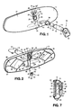
- the support bracket 10 for mounting a mirror case 11 on a vehicle windshield (not shown).
- the support bracket 10 is of the double articulating ball type known in the art and comprises a support member 12 which is slidably received on a base member (not shown) the base member being fixed to a vehicle windshield, the base member and support member 12 having complementary engaging surfaces as is known in the art so that the support member 12 is blow releasable from the base member.
- the support bracket 10 further comprises a rearview mirror mounting arm 13 which is mounted to the support member 12 by means of a ball member 14 as is known for example from U.S. Patent 4,936,533 to Donnelly.
- a further ball member 15 is mounted within the end 16 of the arm 13 the ball member 15 having integrally formed therewith a ball member 17 spaced from ball member 15 by a neck 18. As will be described, the ball member 17 is engaged with a mirror case 11 so that the position of the case 11 is adjustable on the ball member 17.
- a retaining means in the form of a cylindrical protrusion 19 is formed on the ball member 17 and acts to substantially prevent disengagement of the mirror case from the ball member 17.
- the protrusion 19 and ball member 17 may optionally be hollow to accommodate an electrical lead (not shown).
- the support bracket 10 may comprise other known types of support bracket for example that described in U.S. Patent No. 5,058,851, the important aspect being that the mirror case is mounted by means of a ball and socket type arrangement according to the conventional technique for universally adjustable support of a mirror case.
- the ball member onto which the mirror case 11 is mounted is provided with a retaining means to substantially prevent the disengagement of the mirror case 11 from the support bracket 10.
- the retaining means 19 further enables the angle of pivoting of the mirror case 11 relative to the bracket 10 to be limited if desired.
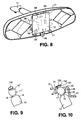
- FIG 9 there is shown a further embodiment of a member 17' for engaging with a mirror case socket.
- the member 17' is similar to the member 17 ( Figure 1) but the protrusion 19'is further provided with flange means or lock means optionally in the form of a circular disc member 100 integrally formed with the member 17'.
- the disc member 100 has a slightly bevelled edge 101.
- the member 17' cooperates with the socket 22 of the mirror case 21 and as shown in Figure 10 the flange means 100 substantially prevents any possibility of the mirror case 21 being removed from the mounting arm 13 and member 17'.
- the socket 22 is of similar construction to that of Figure 1. As shown, as the case 21 moves relative to the member 17', eventually the stage is reached where the edge 102 of the disc member 100 engages with the rim 33 of the socket 22 to further prevent any disengagement of the case 21 from the member 17'.
- the mirror case 11 of Figure 1 comprises a curved mirror case body 21 having an integrally formed socket 22 for receiving the ball member 17 of the support bracket 10.
- the socket 22 is formed in a recess 23 of the case body 21 and projects rearwardly of a generally flat wall region 24.
- the socket 22 comprises a first cylindrical wall 25 defining at least a partly spherical recess 26 ( Figure 7) for accommodating the spherical ball member 17.
- a second wall 27 extends rearwardly of said first wall 25, the second wall being of less thickness than the first wall and has an inherent resilience to enable the spherical ball member 17 to be forced into the partly spherical recess 26.
- Three equiangular slots 28 are provided in the second wall 27 and extend partly into the first wall 25 such that the second wall 27 effectively comprises three part cylindrical resilient flanges 29.
- the flanges 29 of the socket 22 taper outwardly so that the thickness of the flanges 29 reduces towards their free ends 30.
- the diameter of the partly spherical recess 26 is greatest where the wall 25 meets the flanges 29 and the diameter of the recess 26 reduces towards its narrowest at the region 31, which defines the diameter of an aperture 32 opening into the interior of the mirror case 11.
- An integral strengthening rim 33 is provided around the aperture 32, with the inner surface 34 of the rim 33 being bevelled slightly towards the interior of the mirror case 11 as shown. In practice the angle of the bevel is 25° relative to a notional horizontal plane.
- the ball member 17 is a push fit into the recess 26 such that the mirror case 11 is securely mounted on the ball member 17 but enables adjustment of the mirror case position on the ball member 17.
- the cylindrical protrusion 19 projects slightly into the interior of the mirror case 11 as shown in Figure 2, so that movement of the mirror case 11 relative to the ball member 17 is limited by the surface 34 of the rim 33 abutting against the protrusion 19.
- the protrusion 19 acts as a retaining means and results in the advantageous feature that the mirror case 11 is substantially prevented from disengaging from the bracket 10. This is of particular merit since if a user could accidentally remove a mirror case 11 from a supporting bracket 10 it can be extremely difficult to have the mirror case 11 replaced once again.
- the flanges 29 are forced apart slightly as may be the outermost part of the first wall 25. Since the slots 28 extend slightly into the first wall 25, the outermost edge of the first wall adjacent to the slots 28 is also slightly resilient to enable the ball member 17 to be forced into the recess 26.
- a resilient split ring 35 is provided (Figure 1) which is a snap fit around the flanges 29 to embrace the flanges and hold them securely to further prevent any unexpected removal of the ball member 17 from the recess 26.
- the socket 22 being integrally formed with the mirror case 20 has a number of significant advantages including a substantially simplified construction involving only the minimum number of parts and the construction is thus extremely cost effective, resulting in a low cost assembly and a minimum possibility of vibration, of the mirror case.
- FIG 2 there is shown the interior of the mirror casing 11.
- a plurality of support flanges 36 are integrally formed on the interior surface 37 of the case body 21 the flanges 36 being arranged to provide support for a reflective element, to be described below.
- a hollow socket 38 is provided in the case body 21 to accommodate a forward facing light sensor (Figure 5), the socket 38 having an opening 41 in the rear of the case ( Figure 1).
- a press button 42 for a switch is also shown in Figure 2 and comprises a hollow rubber member 43 having a peripheral flange 44.
- the press button 42 has an aperture 45 defined by a resilient internal flange 53.
- the press button 42 is engaged on the operating arm 47 of a two position switch 48 ( Figure 5) so that the flange 53 engages with the recess 46 on the operating arm 47 of the switch 48 thus connecting the button 42 to the switch 48.
- the bezel 91 also has a flange 50 which engages around the flange 44 of the button. In the assembled mirror, the flange 44 prevents the button 42 from disengaging from the switch 48.
- the bottom 51 of the case 21 is provided with an opening 52 to accommodate the lower part 49 of the button 42.
- a cross section of a laminate type electro optic reflective element 40 is shown in Figure 4, the element 40 optionally and preferably comprising a clear front glass 60 and a mirror 61 having a reflective coating 62 applied to its rear surface 63.
- the front glass 60 and mirror 61 are slightly offset relative to each other so that at the upper end the mirror 61 projects below the front glass 60 and at the lower end the front glass 60 projects above the mirror 61.
- An electro-optic layer 64 is sandwiched in a space between the front glass 60 and the mirror 61 and extends onto the exposed front surface 65 of the mirror 61 at the lower end of the element and also onto the exposed rear surface 66 of the front glass 60 at the upper end of the element.
- the front surface 65 of the mirror 61 and the rear surface 66 of the front glass 60 each have a transparent electronic conductor such as indium tin oxide or doped tin oxide or the like as conventionally known in the electro-optic device art.
- An electrical contact in the form of a metal connector strip 67 is secured to the top of the front glass 60 so that it makes electrical contact with the electro-optic layer 64.
- a further electrical contact in the form of a metal connector strip 68 is secured to the lower end of the mirror 61 so that another electrical contact is made with the electro-optic layer.
- the strips 67, 68 are connected by leads 69, 69' to a plug 70 ( Figure 5) which is in turn plugged into a socket 71 on a printed circuit board 72 as will be described.
- a layer of foam material 73 is adhered to the rear surface of the mirror 61 preferably so as to cover substantially the entire rear surface (aside from where items such as through-the-cell photodetectors and information displays such as compass displays are mounted behind the mirror).
- This foam layer 73 acts, as a resilient means or shock absorber means to reduce the risk of breaking of the front glass 60 and mirror 61 during an impact.
- the layer of foam material 73 is preferably a cross linked polyethylene foam sold under the name ALVEOLIT 3000 TA (2mm thick) sold by Vita Cortex Ltd. of Cork, Ireland and is approximately 2mm in thickness. This foam is sold having an adhesive layer applied to both its front 74 and rear 75 surfaces, these surfaces being covered by a removable sheet of protective foil 76 ( Figure 3).
- the protective foil on the front surface of the foam layer 73 is simply removed so that the adhesive layer is exposed and the layer of foam is applied to the rear surface of the mirror 61.
- the foam material substantially extends at least to the central region of the mirror 61 and more preferably substantially covering the entire rear surface of the mirror.
- the foam material layer 73 may be cut to an exact shape, or the general shape or to any suitable generic shape and can be provided in a roll which has already been established while still attached to a backing material tape or sheet for example the protective foil 76.
- the thickness of the foam layer 73 is at least 0.5mm more preferably at least 1mm and most preferably at least 2mm.
- the thickness of the foam layer 73 is preferably less than 5mm more preferably less than 4mm and most preferably less than 3mm.
- the function of the foam layer 73 is to absorb energy from an impact with the mirror from, for example, a person or object in a vehicle to which the mirror is fitted, and also impact from an air bag in a vehicle. Additionally, the foam layer serves to provide an anti-scatter function in the event of breakage.
- a rear surface 78 of the printed circuit board (PCB) 72 carries the various electrical components of an electrical circuit which is used to control the electro-optic layer 64.
- Any desirable circuit may be employed, for example that described in U.S. Patent No. 4,886,960 to Donnelly, the contents of which are incorporated herein by reference.
- the PCB 72 includes a socket 71 for the plug 70 to electrically connect the electro-optic layer 64 to the circuit on the PCB 72. Further, the PCB 72 includes two sets of electrical pins 79, 79' which are arranged such that when the mirror is assembled, the pins 79, 79' correspond with apertures 80, 80' in the mirror case 21, for connection to a vehicle electrical system.
- a two position electrical switch 48 is also mounted on the PCB 72 and has an operating arm 47 having a recess 46.
- the switch is manufactured by Alps Tohoku Co. Ltd. of Tokyo, Japan.
- the two positions of the switch are "off” and “automatic”, i.e. in the "off” position the control circuit on the PCB 72 is turned off and in the "automatic” position the control circuit applies an electric field to the electro-optic layer 64 dependent on the level of light incident onto forward and rearward light sensors 81, 82, respectively, now to be described.
- the control circuit applies an electric field to the electro-optic layer 64 or medium to cause a change in light transmittance of the layer or medium 64.
- the reflective element has at least two reflective conditions.
- a holder 83 for light sensors 81, 82 is also mounted onto the rear surface 78 of the PCB 72.
- the holder 83 comprises a plastics base member 84 having a rearwardly projecting cylindrical housing 85 with the forward light sensor 81 mounted at the free end of the housing 85.
- a pair of suitable wires (not shown) connect the sensor 81 to the control circuit on the PCB, the wires extending through the housing 85.
- an integral support bracket 87 extends from the holder 83 and forwardly of the rear surface 78 of the PCB 72.
- the support bracket 87 carries the rearward facing light sensor 82 which is electrically connected to the control circuit on the PCB 72 by wires 88 which are bent underneath the PCB 72.
- an LED 77 is mounted on a bracket 95 which is fixed to the rear of the PCB 72.
- the housing 85 is located in the socket 38 so that the forward light sensor 81 looks forwardly through aperture 41 in the mirror case 21.
- the rearward light sensor 82 corresponds with an aperture 90 in the bezel 91 so that the rearward light sensor 82 looks rearwardly of the mirror through aperture 90.
- the bezel 91 has a further aperture 92 through which the LED 77 locates to indicate when the mirror is energised.
- the PCB 72 is located in the mirror case so that it abuts the flanges 96 in the mirror case 21 and the housing 85 of the forward facing light sensor 81 is located in the socket 38.
- a retaining means optionally in the form of one or more pins 97 may be provided on the flanges 96, the pin(s) being a snap fit engagement in aperture(s) 98 in the PCB 72 to hold the PCB 72 firmly in position.
- the protective foil 76 is completely removed from the rear surface 75 of the foam layer 73 and the reflective element is located in the bezel 91.
- the bezel 91 containing the reflective element 40 is then brought together with the mirror case 21 so that the rear surface 75 of the foam layer 73 then adheres to the flanges 36 and the PCB 72 by the adhesive on the rear surface 75.
- the press button 42 located in position on the switch 48 the bezel 91 is secured to the mirror case 21 in conventional manner so that the final assembled mirror unit is as shown in Figure 6 with the rearward facing light sensor 82 located within aperture 90 in the bezel 91.
- the user has simply to press the button 42 upwards to energise the control circuit for the electro-optic layer.
- the foam layer 72 is slightly compressed by the flanges 36 so that the complete structure is quite compact and firmly retained.
- the flanges 36 provide additional shock absorbing properties for the reflective element as does the PCB 72.
- the electro-optic layer 64 may of course comprise any suitable or desirable material, for example electrochromic, liquid crystal or other materials which have desirable electro-optic properties.
- the foam layer of this invention is particularly useful with electrochromic rearview mirror devices, such as those described in U.S. Patent Nos. 5,140,455 and U.S. 5,151,816 and European Application Nos. 92308022.0, or as described for example in the following papers:- N.R. Lynam, "Electrochromic Automotive Day/Night Mirrors", SAE Technical Paper Series , 870636 (1987); N.R. Lynam, “Smart Windows for Automobiles", SAE Technical Paper Series , 900419 (1990); N.R. Lynam and A.
- the support bracket 10 incorporating the protrusion 19 according to the invention may be usefully employed for mounting any type of mirror case onto a vehicle.
- the mirror case 21 incorporating the integral socket 22 may be used for supporting any desired form of reflective element.
- the case 21 and socket 22 are moulded from ABS (Acrylonitrile/Butadiene/Styrene) manufactured by BASF of Ludwigshafen, Germany.
Abstract
Description
- The present invention relates to rearview mirrors for example electro-optic rearview mirrors and in particular to electro-optic rearview mirrors in which two glass plates sandwich an electro-optic medium.
- Brackets for supporting rearview mirrors are well known in the art, for example in U.S. Patent Nos. 4,936,533, 5,058,851, 4,524,941 and 4,012,022. The rearview mirrors are mounted to the brackets by means of a ball and socket connection. A problem with these constructions however is that the mirror casing can in certain circumstances be removed from the bracket. The above prior art Patents also disclose a case for a rearview mirror, i.e. a housing for holding the reflective element. These housings usually have fixed thereto a socket member for receiving the ball part of a support bracket so that the mirror housing is adjustable on the bracket. The number of components which may be employed in construction of such mirror assemblies results in high assembly cost and time, and the possibility of vibration between parts.
- Electro-optic rearview mirrors are well known in the art for example in U.S. 5,140,455, U.S. 5,151,816 and as described in the following paper:- N.R. Lynam, "Electrochromic Automotive Day/Night Mirrors", SAE Technical Paper Series, (870636) (1987).
- According to one aspect of the present invention there is provided a support bracket for mounting an article on a vehicle said support bracket having at one end means for mounting the bracket onto a vehicle and means at the other end for mounting an article, said means for mounting the article further comprising retaining means to substantially prevent disengagement of said article from said bracket.
- Preferably, the article is a vehicle rearview mirror. More preferably the article is a vehicle interior rearview mirror.
- Further preferably, said means for mounting the rearview mirror comprises a generally spherical ball for insertion in a complementary socket provided in the mirror case.
- More preferably, the retaining means comprises a protrusion provided on the spherical ball, said protrusion acting to substantially prevent disengagement of said mirror case from said bracket.
- The protrusion preferably comprises a generally cylindrical member integrally formed with said spherical ball. The protrusion further comprises flange means to further prevent disengagement of said mirror case from said bracket.
- According to a second aspect of the present invention there is provided a rearview mirror case, wherein said case comprises a case body having an integrally formed socket for receiving one end of a complementary support bracket.
- The socket preferably projects rearwardly of said mirror case and comprises a first wall defining at least a partially spherical recess for accommodating a spherical ball provided on one end of a support bracket.
- Further preferably, the socket comprises a second wall extending rearwardly of said first wall, the second wall being less thickness than said first wall and having an inherent resilience to enable the spherical ball of the bracket to be forced into the partially spherical recess.
- A plurality of slots are preferably provided in the second wall, which extend slightly into the first wall, such that the second wall comprises a plurality of wall portions. A resilient tightening split ring is provided to embrace the wall portions of the second wall to cause the second wall portions to close slightly around the spherical ball of the bracket when the spherical ball is accommodated in the socket.
- According to yet a third aspect of the present invention there is provided a reflective element for a rearview mirror, said reflective element comprising a reflective element actuatable between at least two reflective conditions, and shock absorbing means abutting to a rear surface of said reflective element.
- Preferably, said shock absorbing means comprises a layer of foam adhered to the rear surface of the reflective element. The invention further provides a reflective element for a rearview mirror, said reflective element actuatable between at least two reflective conditions and resilient means abutting a rear surface of said reflective element. The resilient means is preferably a layer of resilient material. The resilient material is preferably adhered to the rear surface of the reflective element. The invention further provides a rearview mirror assembly as recited in
Claim 24. - Embodiments of the invention will now be described, by way of example, with reference to the accompanying drawings, in which:
- Figure 1 is a rear perspective view of a mirror support bracket and a mirror case according to the invention;
- Figure 2 is a front perspective view of the mirror case of Figure 1 with the mirror support bracket secured to the mirror case;
- Figure 3 is a rear perspective view of a reflective element and mirror bezel according to the invention;
- Figure 4 is a cross sectional view of the reflective element taken along the lines I-I in Figure 3 but also showing a circuit board on the reflective element;
- Figure 5 is a rear perspective view of the circuit board of Figure 4 and also showing a press button switch;
- Figure 6 is a front perspective view of an assembled rearview mirror according to the invention;
- Figure 7 is a schematic cross-sectional view of the rearview mirror of Figure 6.
- Figure 8 is a front perspective view of the mirror case with the circuit board in place;
- Figure 9 is a perspective view of another embodiment of a ball member for engaging with a mirror case socket; and
- Figure 10 is a schematic cross-sectional view of the ball member of Figure 9 cooperating with a mirror case.
- Referring now to the drawings and in particular to Figure 1, there is shown therein a
support bracket 10 for mounting amirror case 11 on a vehicle windshield (not shown). Thesupport bracket 10 is of the double articulating ball type known in the art and comprises asupport member 12 which is slidably received on a base member (not shown) the base member being fixed to a vehicle windshield, the base member andsupport member 12 having complementary engaging surfaces as is known in the art so that thesupport member 12 is blow releasable from the base member. Thesupport bracket 10 further comprises a rearviewmirror mounting arm 13 which is mounted to thesupport member 12 by means of aball member 14 as is known for example from U.S. Patent 4,936,533 to Donnelly. - A
further ball member 15 is mounted within theend 16 of thearm 13 theball member 15 having integrally formed therewith aball member 17 spaced fromball member 15 by aneck 18. As will be described, theball member 17 is engaged with amirror case 11 so that the position of thecase 11 is adjustable on theball member 17. A retaining means in the form of acylindrical protrusion 19 is formed on theball member 17 and acts to substantially prevent disengagement of the mirror case from theball member 17. Theprotrusion 19 andball member 17 may optionally be hollow to accommodate an electrical lead (not shown). - It will be appreciated that the
support bracket 10 may comprise other known types of support bracket for example that described in U.S. Patent No. 5,058,851, the important aspect being that the mirror case is mounted by means of a ball and socket type arrangement according to the conventional technique for universally adjustable support of a mirror case. However, whichever type of support bracket is employed, the important feature is that the ball member onto which themirror case 11 is mounted is provided with a retaining means to substantially prevent the disengagement of themirror case 11 from thesupport bracket 10. The retaining means 19 further enables the angle of pivoting of themirror case 11 relative to thebracket 10 to be limited if desired. - In Figure 9 there is shown a further embodiment of a member 17' for engaging with a mirror case socket. The member 17' is similar to the member 17 (Figure 1) but the protrusion 19'is further provided with flange means or lock means optionally in the form of a
circular disc member 100 integrally formed with the member 17'. As shown more clearly in Figure 10, thedisc member 100 has a slightlybevelled edge 101. The member 17' cooperates with thesocket 22 of themirror case 21 and as shown in Figure 10 the flange means 100 substantially prevents any possibility of themirror case 21 being removed from themounting arm 13 and member 17'. It will be appreciated that thesocket 22 is of similar construction to that of Figure 1. As shown, as thecase 21 moves relative to the member 17', eventually the stage is reached where theedge 102 of thedisc member 100 engages with therim 33 of thesocket 22 to further prevent any disengagement of thecase 21 from the member 17'. - The
mirror case 11 of Figure 1 comprises a curvedmirror case body 21 having an integrally formedsocket 22 for receiving theball member 17 of thesupport bracket 10. Thesocket 22 is formed in arecess 23 of thecase body 21 and projects rearwardly of a generallyflat wall region 24. Thesocket 22 comprises a firstcylindrical wall 25 defining at least a partly spherical recess 26 (Figure 7) for accommodating thespherical ball member 17. Asecond wall 27 extends rearwardly of saidfirst wall 25, the second wall being of less thickness than the first wall and has an inherent resilience to enable thespherical ball member 17 to be forced into the partlyspherical recess 26. Threeequiangular slots 28 are provided in thesecond wall 27 and extend partly into thefirst wall 25 such that thesecond wall 27 effectively comprises three part cylindricalresilient flanges 29. - As shown more clearly in Figure 7, the
flanges 29 of thesocket 22 taper outwardly so that the thickness of theflanges 29 reduces towards theirfree ends 30. Also, the diameter of the partlyspherical recess 26 is greatest where thewall 25 meets theflanges 29 and the diameter of therecess 26 reduces towards its narrowest at theregion 31, which defines the diameter of anaperture 32 opening into the interior of themirror case 11. An integral strengtheningrim 33 is provided around theaperture 32, with theinner surface 34 of therim 33 being bevelled slightly towards the interior of themirror case 11 as shown.
In practice the angle of the bevel is 25° relative to a notional horizontal plane. - The
ball member 17 is a push fit into therecess 26 such that themirror case 11 is securely mounted on theball member 17 but enables adjustment of the mirror case position on theball member 17. With theball member 17 accommodated in therecess 26, thecylindrical protrusion 19 projects slightly into the interior of themirror case 11 as shown in Figure 2, so that movement of themirror case 11 relative to theball member 17 is limited by thesurface 34 of therim 33 abutting against theprotrusion 19. It will be noted however that when thesurface 34 abuts theprotrusion 19, it is difficult for themirror case 11 to be disengaged from theball member 17. Thus, theprotrusion 19 acts as a retaining means and results in the advantageous feature that themirror case 11 is substantially prevented from disengaging from thebracket 10. This is of particular merit since if a user could accidentally remove amirror case 11 from a supportingbracket 10 it can be extremely difficult to have themirror case 11 replaced once again. - In engaging the
ball member 17 into therecess 26, theflanges 29 are forced apart slightly as may be the outermost part of thefirst wall 25. Since theslots 28 extend slightly into thefirst wall 25, the outermost edge of the first wall adjacent to theslots 28 is also slightly resilient to enable theball member 17 to be forced into therecess 26. - A
resilient split ring 35 is provided (Figure 1) which is a snap fit around theflanges 29 to embrace the flanges and hold them securely to further prevent any unexpected removal of theball member 17 from therecess 26. - The
socket 22 being integrally formed with the mirror case 20 has a number of significant advantages including a substantially simplified construction involving only the minimum number of parts and the construction is thus extremely cost effective, resulting in a low cost assembly and a minimum possibility of vibration, of the mirror case. - In figure 2 there is shown the interior of the
mirror casing 11. A plurality ofsupport flanges 36 are integrally formed on theinterior surface 37 of thecase body 21 theflanges 36 being arranged to provide support for a reflective element, to be described below. Ahollow socket 38 is provided in thecase body 21 to accommodate a forward facing light sensor (Figure 5), thesocket 38 having anopening 41 in the rear of the case (Figure 1). - A
press button 42 for a switch is also shown in Figure 2 and comprises ahollow rubber member 43 having aperipheral flange 44. Thepress button 42 has anaperture 45 defined by a resilientinternal flange 53. Thepress button 42 is engaged on theoperating arm 47 of a two position switch 48 (Figure 5) so that theflange 53 engages with therecess 46 on theoperating arm 47 of theswitch 48 thus connecting thebutton 42 to theswitch 48. Thebezel 91 also has aflange 50 which engages around theflange 44 of the button. In the assembled mirror, theflange 44 prevents thebutton 42 from disengaging from theswitch 48. The bottom 51 of thecase 21 is provided with anopening 52 to accommodate thelower part 49 of thebutton 42. - A cross section of a laminate type electro optic
reflective element 40 is shown in Figure 4, theelement 40 optionally and preferably comprising aclear front glass 60 and amirror 61 having areflective coating 62 applied to itsrear surface 63. As shown, thefront glass 60 andmirror 61 are slightly offset relative to each other so that at the upper end themirror 61 projects below thefront glass 60 and at the lower end thefront glass 60 projects above themirror 61. An electro-optic layer 64 is sandwiched in a space between thefront glass 60 and themirror 61 and extends onto the exposedfront surface 65 of themirror 61 at the lower end of the element and also onto the exposedrear surface 66 of thefront glass 60 at the upper end of the element. It will be appreciated that thefront surface 65 of themirror 61 and therear surface 66 of thefront glass 60 each have a transparent electronic conductor such as indium tin oxide or doped tin oxide or the like as conventionally known in the electro-optic device art. An electrical contact in the form of ametal connector strip 67 is secured to the top of thefront glass 60 so that it makes electrical contact with the electro-optic layer 64. Similarly, a further electrical contact in the form of ametal connector strip 68 is secured to the lower end of themirror 61 so that another electrical contact is made with the electro-optic layer. Thestrips socket 71 on a printedcircuit board 72 as will be described. - A layer of
foam material 73, is adhered to the rear surface of themirror 61 preferably so as to cover substantially the entire rear surface (aside from where items such as through-the-cell photodetectors and information displays such as compass displays are mounted behind the mirror). Thisfoam layer 73 acts, as a resilient means or shock absorber means to reduce the risk of breaking of thefront glass 60 andmirror 61 during an impact. The layer offoam material 73 is preferably a cross linked polyethylene foam sold under the name ALVEOLIT 3000 TA (2mm thick) sold by Vita Cortex Ltd. of Cork, Ireland and is approximately 2mm in thickness. This foam is sold having an adhesive layer applied to both itsfront 74 and rear 75 surfaces, these surfaces being covered by a removable sheet of protective foil 76 (Figure 3). The protective foil on the front surface of thefoam layer 73 is simply removed so that the adhesive layer is exposed and the layer of foam is applied to the rear surface of themirror 61. The foam material substantially extends at least to the central region of themirror 61 and more preferably substantially covering the entire rear surface of the mirror. Thefoam material layer 73 may be cut to an exact shape, or the general shape or to any suitable generic shape and can be provided in a roll which has already been established while still attached to a backing material tape or sheet for example theprotective foil 76. The thickness of thefoam layer 73 is at least 0.5mm more preferably at least 1mm and most preferably at least 2mm. The thickness of thefoam layer 73 is preferably less than 5mm more preferably less than 4mm and most preferably less than 3mm. The function of thefoam layer 73 is to absorb energy from an impact with the mirror from, for example, a person or object in a vehicle to which the mirror is fitted, and also impact from an air bag in a vehicle. Additionally, the foam layer serves to provide an anti-scatter function in the event of breakage. - A
rear surface 78 of the printed circuit board (PCB) 72 carries the various electrical components of an electrical circuit which is used to control the electro-optic layer 64. Any desirable circuit may be employed, for example that described in U.S. Patent No. 4,886,960 to Donnelly, the contents of which are incorporated herein by reference. - The
PCB 72 includes asocket 71 for theplug 70 to electrically connect the electro-optic layer 64 to the circuit on thePCB 72. Further, thePCB 72 includes two sets ofelectrical pins 79, 79' which are arranged such that when the mirror is assembled, thepins 79, 79' correspond withapertures 80, 80' in themirror case 21, for connection to a vehicle electrical system. - A two position
electrical switch 48 is also mounted on thePCB 72 and has anoperating arm 47 having arecess 46. The switch is manufactured by Alps Tohoku Co. Ltd. of Tokyo, Japan. The two positions of the switch are "off" and "automatic", i.e. in the "off" position the control circuit on thePCB 72 is turned off and in the "automatic" position the control circuit applies an electric field to the electro-optic layer 64 dependent on the level of light incident onto forward and rearwardlight sensors optic layer 64 or medium to cause a change in light transmittance of the layer ormedium 64. Thus, the reflective element has at least two reflective conditions. - A
holder 83 forlight sensors rear surface 78 of thePCB 72. Theholder 83 comprises aplastics base member 84 having a rearwardly projectingcylindrical housing 85 with theforward light sensor 81 mounted at the free end of thehousing 85. A pair of suitable wires (not shown) connect thesensor 81 to the control circuit on the PCB, the wires extending through thehousing 85. As shown, anintegral support bracket 87 extends from theholder 83 and forwardly of therear surface 78 of thePCB 72. Thesupport bracket 87 carries the rearward facinglight sensor 82 which is electrically connected to the control circuit on thePCB 72 bywires 88 which are bent underneath thePCB 72. Also, anLED 77 is mounted on abracket 95 which is fixed to the rear of thePCB 72. - During assembly of the mirror, the
housing 85 is located in thesocket 38 so that theforward light sensor 81 looks forwardly throughaperture 41 in themirror case 21. The rearwardlight sensor 82 corresponds with anaperture 90 in thebezel 91 so that the rearwardlight sensor 82 looks rearwardly of the mirror throughaperture 90. Thebezel 91 has afurther aperture 92 through which theLED 77 locates to indicate when the mirror is energised. - In completing the assembly, the
PCB 72 is located in the mirror case so that it abuts theflanges 96 in themirror case 21 and thehousing 85 of the forward facinglight sensor 81 is located in thesocket 38. Also, a retaining means optionally in the form of one ormore pins 97 may be provided on theflanges 96, the pin(s) being a snap fit engagement in aperture(s) 98 in thePCB 72 to hold thePCB 72 firmly in position. Theprotective foil 76 is completely removed from therear surface 75 of thefoam layer 73 and the reflective element is located in thebezel 91. Thebezel 91 containing thereflective element 40 is then brought together with themirror case 21 so that therear surface 75 of thefoam layer 73 then adheres to theflanges 36 and thePCB 72 by the adhesive on therear surface 75. With thepress button 42 located in position on theswitch 48 thebezel 91 is secured to themirror case 21 in conventional manner so that the final assembled mirror unit is as shown in Figure 6 with the rearward facinglight sensor 82 located withinaperture 90 in thebezel 91. The user has simply to press thebutton 42 upwards to energise the control circuit for the electro-optic layer. - When the
bezel 91 is secured in place thefoam layer 72 is slightly compressed by theflanges 36 so that the complete structure is quite compact and firmly retained. Theflanges 36 provide additional shock absorbing properties for the reflective element as does thePCB 72. - The electro-
optic layer 64 may of course comprise any suitable or desirable material, for example electrochromic, liquid crystal or other materials which have desirable electro-optic properties. The foam layer of this invention is particularly useful with electrochromic rearview mirror devices, such as those described in U.S. Patent Nos. 5,140,455 and U.S. 5,151,816 and European Application Nos. 92308022.0, or as described for example in the following papers:- N.R. Lynam, "Electrochromic Automotive Day/Night Mirrors", SAE Technical Paper Series, 870636 (1987); N.R. Lynam, "Smart Windows for Automobiles", SAE Technical Paper Series, 900419 (1990); N.R. Lynam and A. Agrawal, "Automotive Applications of Chromogenic Materials", Large Area Chromogenics: Materials & Devices for Transmittance Control, C.M. Lampert and C.G. Granquist, eds., Optical Eng'g Press, Washington (1990). - It will be appreciated that the
support bracket 10 incorporating theprotrusion 19 according to the invention may be usefully employed for mounting any type of mirror case onto a vehicle. Further, it will be appreciated that themirror case 21 incorporating theintegral socket 22 may be used for supporting any desired form of reflective element. Thecase 21 andsocket 22 are moulded from ABS (Acrylonitrile/Butadiene/Styrene) manufactured by BASF of Ludwigshafen, Germany.
Claims (11)
- A support bracket for mounting an article on a vehicle said support bracket having at one end means for mounting the bracket onto a vehicle and means at the other end for mounting an article, said means for mounting the article further comprising retaining means to substantially prevent disengagement of said article from said bracket.
- A support bracket as claimed in Claim 1, wherein the article is a vehicle rearview mirror.
- A support bracket as claimed in Claim 1 or 2, wherein the article is a vehicle interior rearview mirror.
- A support bracket as claimed in Claim 2 or 3, wherein said means for mounting the rearview mirror comprises a generally spherical ball for insertion in a complementary socket provided in a mirror case of the rearview mirror.
- A support bracket as claimed in Claim 4, wherein the retaining means comprises a protrusion provided on the spherical ball, said protrusion acting to substantially prevent disengagement of said mirror case from said bracket.
- A support bracket as claimed in Claim 5 wherein the protrusion comprises a generally cylindrical member integrally formed with said spherical ball.
- A support bracket as claimed in Claim 6 wherein said protrusion comprises flange means to further prevent disengagement of said mirror case from said bracket.
- A rearview mirror case, wherein said case comprises a case body having an integrally formed socket for receiving one end of a complementary support bracket.
- A reflective element for a rearview mirror, said reflective element comprising a reflective element actuatable between at least two reflective conditions, and shock absorbing means abutting a rear surface of said reflective element.
- A rearview mirror assembly comprising first and second spaced optically transparent elements mounted in a mirror case, each having front and rear surfaces and defining a space between the rear surface of the first element and the front surface of the second element, an electro-optic medium confined in said space whose light transmittance is variable upon the application of an electric field thereto; means for applying an electric field to the electro-optic medium to cause a change in the light transmittance of said medium; a reflective coating on one surface of said second element to reflect light incident thereon through said electro-optic medium and said first element; and shock absorbing means adhered to the rear surface of said second element for reducing the risk of breaking of said first and second elements.
- A reflective element for a rearview mirror, said reflective element actuatable between at least two reflective conditions and resilient means abutting a rear surface of said reflective element.
Applications Claiming Priority (6)
| Application Number | Priority Date | Filing Date | Title |
|---|---|---|---|
| IE930211 | 1993-03-19 | ||
| IE930210 | 1993-03-19 | ||
| IE930212 | 1993-03-19 | ||
| IE930211 | 1993-03-19 | ||
| IE930210 | 1993-03-19 | ||
| IE930212 | 1993-03-19 |
Publications (2)
| Publication Number | Publication Date |
|---|---|
| EP0615882A2 true EP0615882A2 (en) | 1994-09-21 |
| EP0615882A3 EP0615882A3 (en) | 1994-11-02 |
Family
ID=27270460
Family Applications (1)
| Application Number | Title | Priority Date | Filing Date |
|---|---|---|---|
| EP9494650008A Withdrawn EP0615882A3 (en) | 1993-03-19 | 1994-03-18 | Rearview mirror assembly. |
Country Status (3)
| Country | Link |
|---|---|
| US (1) | US5572354A (en) |
| EP (1) | EP0615882A3 (en) |
| JP (1) | JPH0747880A (en) |
Cited By (24)
| Publication number | Priority date | Publication date | Assignee | Title |
|---|---|---|---|---|
| WO1995033139A1 (en) * | 1994-05-31 | 1995-12-07 | Itt Automotive Electrical Systems, Inc. | Integral tophat linkball |
| US5669698A (en) * | 1995-05-24 | 1997-09-23 | Veldman; Roger L. | Modular rearview mirror assembly and method for making same |
| US5671996A (en) * | 1994-12-30 | 1997-09-30 | Donnelly Corporation | Vehicle instrumentation/console lighting |
| US5820245A (en) * | 1995-12-11 | 1998-10-13 | Donnelly Corporation | Rearview mirror assembly |
| EP0899157A1 (en) * | 1997-08-25 | 1999-03-03 | Donnelly Corporation | Modular rearview mirror assembly |
| US6000823A (en) * | 1995-12-11 | 1999-12-14 | Donnelly Mirrors Limited | Rearview mirror assembly |
| US6329925B1 (en) | 1999-11-24 | 2001-12-11 | Donnelly Corporation | Rearview mirror assembly with added feature modular display |
| US6648477B2 (en) | 2000-07-06 | 2003-11-18 | Donnelly Corporation | Rearview mirror assembly with information display |
| US6953905B2 (en) | 2002-07-18 | 2005-10-11 | Maxera Llc | Electrical switch |
| US7224324B2 (en) | 2000-03-27 | 2007-05-29 | Donnelly Corporation | Interactive automotive rearvision system |
| EP1449719B1 (en) * | 2001-11-26 | 2009-09-30 | Grupo Antolin-Ingenieria, S.A. | Breakage-prevention support structure for mirrors mounted inside a vehicle |
| US7815326B2 (en) | 2002-06-06 | 2010-10-19 | Donnelly Corporation | Interior rearview mirror system |
| US7826123B2 (en) | 2002-09-20 | 2010-11-02 | Donnelly Corporation | Vehicular interior electrochromic rearview mirror assembly |
| US7832882B2 (en) | 2002-06-06 | 2010-11-16 | Donnelly Corporation | Information mirror system |
| US7859737B2 (en) | 2002-09-20 | 2010-12-28 | Donnelly Corporation | Interior rearview mirror system for a vehicle |
| US7864399B2 (en) | 2002-09-20 | 2011-01-04 | Donnelly Corporation | Reflective mirror assembly |
| US7888629B2 (en) | 1998-01-07 | 2011-02-15 | Donnelly Corporation | Vehicular accessory mounting system with a forwardly-viewing camera |
| US7898398B2 (en) | 1997-08-25 | 2011-03-01 | Donnelly Corporation | Interior mirror system |
| US7906756B2 (en) | 2002-05-03 | 2011-03-15 | Donnelly Corporation | Vehicle rearview mirror system |
| US7916009B2 (en) | 1998-01-07 | 2011-03-29 | Donnelly Corporation | Accessory mounting system suitable for use in a vehicle |
| US8179236B2 (en) | 2000-03-02 | 2012-05-15 | Donnelly Corporation | Video mirror system suitable for use in a vehicle |
| US8294975B2 (en) | 1997-08-25 | 2012-10-23 | Donnelly Corporation | Automotive rearview mirror assembly |
| US8462204B2 (en) | 1995-05-22 | 2013-06-11 | Donnelly Corporation | Vehicular vision system |
| CN105365675A (en) * | 2015-11-26 | 2016-03-02 | 重庆奥科伦实业发展有限公司 | Automobile internal rearview mirror with internal shock absorption structure |
Families Citing this family (76)
| Publication number | Priority date | Publication date | Assignee | Title |
|---|---|---|---|---|
| EP0612826B1 (en) * | 1993-02-26 | 2000-10-04 | Donnelly Corporation | Electrochromic polymeric solid films, manufacturing electrochromic devices using such solid films, and processing for making such solid films and devices |
| US5910854A (en) | 1993-02-26 | 1999-06-08 | Donnelly Corporation | Electrochromic polymeric solid films, manufacturing electrochromic devices using such solid films, and processes for making such solid films and devices |
| US5668663A (en) | 1994-05-05 | 1997-09-16 | Donnelly Corporation | Electrochromic mirrors and devices |
| US5798688A (en) * | 1997-02-07 | 1998-08-25 | Donnelly Corporation | Interior vehicle mirror assembly having communication module |
| US6087953A (en) | 1998-02-18 | 2000-07-11 | Donnelly Corporation | Rearview mirror support incorporating vehicle information display |
| US6089523A (en) * | 1997-08-29 | 2000-07-18 | Lear Automative Dearborn, Inc. | Integral mirror bracket using gas assist |
| US6278377B1 (en) | 1999-08-25 | 2001-08-21 | Donnelly Corporation | Indicator for vehicle accessory |
| US8288711B2 (en) | 1998-01-07 | 2012-10-16 | Donnelly Corporation | Interior rearview mirror system with forwardly-viewing camera and a control |
| US6693517B2 (en) | 2000-04-21 | 2004-02-17 | Donnelly Corporation | Vehicle mirror assembly communicating wirelessly with vehicle accessories and occupants |
| US6420975B1 (en) | 1999-08-25 | 2002-07-16 | Donnelly Corporation | Interior rearview mirror sound processing system |
| US6477464B2 (en) | 2000-03-09 | 2002-11-05 | Donnelly Corporation | Complete mirror-based global-positioning system (GPS) navigation solution |
| US6428172B1 (en) | 1999-11-24 | 2002-08-06 | Donnelly Corporation | Rearview mirror assembly with utility functions |
| US5984482A (en) * | 1998-07-28 | 1999-11-16 | Gentex Corporation | Mounting assembly for vehicle interior automatic dimming rearview mirror |
| US6068380A (en) * | 1998-07-28 | 2000-05-30 | Gentex Corporation | Mirror mount having an integral spherical bearing |
| US6170956B1 (en) * | 1998-10-14 | 2001-01-09 | Gentex Corporation | Rearview mirror with display |
| US6244716B1 (en) * | 1999-05-17 | 2001-06-12 | Gentex Corporation | Exterior mirror sub-assembly with combined electronic circuitry and mirror element |
| DE60028907T2 (en) | 1999-11-24 | 2007-02-15 | Donnelly Corp., Holland | Rearview mirror with utility function |
| US6540193B1 (en) * | 1999-12-23 | 2003-04-01 | Donnelly Corporation | Rearview mirror mounting assembly |
| WO2001064481A2 (en) | 2000-03-02 | 2001-09-07 | Donnelly Corporation | Video mirror systems incorporating an accessory module |
| US7480149B2 (en) | 2004-08-18 | 2009-01-20 | Donnelly Corporation | Accessory module for vehicle |
| US7370983B2 (en) | 2000-03-02 | 2008-05-13 | Donnelly Corporation | Interior mirror assembly with display |
| US7167796B2 (en) | 2000-03-09 | 2007-01-23 | Donnelly Corporation | Vehicle navigation system for use with a telematics system |
| US6396408B2 (en) | 2000-03-31 | 2002-05-28 | Donnelly Corporation | Digital electrochromic circuit with a vehicle network |
| US6698905B1 (en) * | 2000-05-16 | 2004-03-02 | Donnelly Corporation | Memory mirror system for vehicle |
| WO2002058189A1 (en) | 2000-10-20 | 2002-07-25 | Donnelly Corporation | Exterior mirror with antenna |
| US6877709B2 (en) * | 2000-12-21 | 2005-04-12 | Donnelly Corporation | Interior rearview mirror assembly with polymeric components |
| DE60220379T2 (en) | 2001-01-23 | 2008-01-24 | Donnelly Corp., Holland | IMPROVED VEHICLE LIGHTING SYSTEM |
| US7581859B2 (en) | 2005-09-14 | 2009-09-01 | Donnelly Corp. | Display device for exterior rearview mirror |
| JP2003146134A (en) * | 2001-11-14 | 2003-05-21 | Ichikoh Ind Ltd | Inner mirror device |
| DE60125992T2 (en) | 2001-11-16 | 2007-11-08 | Murakami Corp. | ACCESSORY HOLDER IN CABIN |
| US6824281B2 (en) | 2002-01-31 | 2004-11-30 | Donnelly Corporation | Vehicle accessory module |
| EP1523432B1 (en) * | 2002-04-26 | 2010-09-08 | Magna Donnelly Engineering GmbH | Rearview mirror assemblies |
| US20060061008A1 (en) | 2004-09-14 | 2006-03-23 | Lee Karner | Mounting assembly for vehicle interior mirror |
| US10144353B2 (en) | 2002-08-21 | 2018-12-04 | Magna Electronics Inc. | Multi-camera vision system for a vehicle |
| US7360932B2 (en) | 2004-06-01 | 2008-04-22 | Donnelly Corporation | Mirror assembly for vehicle |
| WO2004103772A2 (en) | 2003-05-19 | 2004-12-02 | Donnelly Corporation | Mirror assembly for vehicle |
| US7287868B2 (en) * | 2003-04-02 | 2007-10-30 | Gentex Corporation | Rearview mirror with integrated frame |
| US7446427B2 (en) * | 2003-05-20 | 2008-11-04 | Gentex Corporation | Rearview mirror system for accommodating a rain sensor |
| US7249860B2 (en) * | 2003-09-05 | 2007-07-31 | Donnelly Corporation | Interior rearview mirror assembly |
| US7446924B2 (en) | 2003-10-02 | 2008-11-04 | Donnelly Corporation | Mirror reflective element assembly including electronic component |
| US7308341B2 (en) | 2003-10-14 | 2007-12-11 | Donnelly Corporation | Vehicle communication system |
| US20050128610A1 (en) * | 2003-11-03 | 2005-06-16 | Parker Brian R. | Rearview mirror assembly including a housing having a wiring cover |
| US20050152054A1 (en) * | 2004-01-14 | 2005-07-14 | Gentex Corporation | Reflective element holder for rearview mirror |
| EP1827908B1 (en) | 2004-12-15 | 2015-04-29 | Magna Electronics Inc. | An accessory module system for a vehicle window |
| US7216885B1 (en) * | 2004-12-21 | 2007-05-15 | Brian Stopka | Trailer mounted and adjustable mirror assembly |
| US7626749B2 (en) | 2005-05-16 | 2009-12-01 | Donnelly Corporation | Vehicle mirror assembly with indicia at reflective element |
| US7510287B2 (en) * | 2005-10-21 | 2009-03-31 | Donnelly Corporation | Wire cover assembly for vehicle interior mirror |
| US8345345B2 (en) | 2007-06-27 | 2013-01-01 | Gentex Corporation | Electrochromic device having an improved fill port plug |
| US7884995B2 (en) * | 2007-06-27 | 2011-02-08 | Gentex Corporation | Electrochromic device having an improved fill port plug |
| US8154418B2 (en) | 2008-03-31 | 2012-04-10 | Magna Mirrors Of America, Inc. | Interior rearview mirror system |
| JP5123063B2 (en) | 2008-06-12 | 2013-01-16 | 株式会社東海理化電機製作所 | Pivot connection structure of inner mirror device for vehicle |
| US9487144B2 (en) | 2008-10-16 | 2016-11-08 | Magna Mirrors Of America, Inc. | Interior mirror assembly with display |
| US8570374B2 (en) | 2008-11-13 | 2013-10-29 | Magna Electronics Inc. | Camera for vehicle |
| US8451332B2 (en) | 2009-03-23 | 2013-05-28 | Magna Mirrors Of America, Inc. | Interior mirror assembly with adjustable mounting assembly |
| KR101142226B1 (en) * | 2009-05-29 | 2012-05-04 | 에스엠알 페턴츠 에스.에이.알.엘. | Stay for the inside mirror of the vehicle |
| US8851690B2 (en) | 2009-10-27 | 2014-10-07 | Magna Mirrors Of America, Inc. | Mounting assembly for vehicle interior mirror |
| US8899761B2 (en) | 2011-03-23 | 2014-12-02 | Gentex Corporation | Lens cleaning apparatus |
| US20130112836A1 (en) * | 2011-11-07 | 2013-05-09 | Magna Mirrors Of America, Inc. | Interior mirror mounting assembly with integrally formed metallic ball and arm |
| US9436005B2 (en) | 2012-08-02 | 2016-09-06 | Gentex Corporation | Amplified piezoelectric camera lens cleaner |
| US9352691B2 (en) | 2012-11-05 | 2016-05-31 | Magna Mirrors Of America, Inc. | Interior rearview mirror assembly |
| US10012530B2 (en) | 2013-03-14 | 2018-07-03 | Gentex Corporation | Light sensing device |
| US9057925B2 (en) | 2013-03-15 | 2015-06-16 | Gentex Corporation | Fill port plugs for electrochromic devices |
| US9454054B2 (en) | 2013-11-18 | 2016-09-27 | Magna Mirrors Of America, Inc. | Electro-optic mirror element and process of making same |
| CN204077516U (en) | 2014-08-01 | 2015-01-07 | 潘磊 | A kind of removable inside-automobile rear mirror support |
| JP6463158B2 (en) * | 2015-02-05 | 2019-01-30 | 株式会社東海理化電機製作所 | Vehicle visual recognition device |
| USD804376S1 (en) | 2016-10-27 | 2017-12-05 | Gentex Corporation | Rearview assembly |
| USD804377S1 (en) | 2016-10-27 | 2017-12-05 | Gentex Corporation | Rearview assembly |
| CN210310146U (en) | 2016-11-07 | 2020-04-14 | 金泰克斯公司 | Rearview mirror assembly |
| USD823204S1 (en) | 2016-12-16 | 2018-07-17 | Gentex Corporation | Outside rearview assembly with turn signal |
| USD830260S1 (en) | 2017-01-03 | 2018-10-09 | Gentex Corporation | External rearview mirror |
| USD837112S1 (en) | 2017-01-03 | 2019-01-01 | Gentex Corporation | Side view mirror electro optic device with blind spot indicator portion |
| US11578752B2 (en) * | 2017-01-06 | 2023-02-14 | Robert Bosch Gmbh | Ball joint with locking ball socket assembly |
| CN211223225U (en) * | 2017-03-10 | 2020-08-11 | 金泰克斯公司 | Rearview mirror assembly |
| US10414341B2 (en) * | 2017-06-29 | 2019-09-17 | Global Media Industry Group Co., Ltd. | Automobile interior rearview mirror |
| EP3860880B1 (en) * | 2018-10-02 | 2022-12-21 | Gentex Corporation | Adjustable mounting mechanism for a rearview assembly |
| US11414014B2 (en) * | 2020-02-24 | 2022-08-16 | Magna Mirrors Of America, Inc. | Interior rearview mirror assembly with circuitry at mirror mount |
Citations (3)
| Publication number | Priority date | Publication date | Assignee | Title |
|---|---|---|---|---|
| GB885198A (en) * | 1959-09-25 | 1961-12-20 | Bosch Gmbh Robert | Improvements in or relating to ball and socket joints |
| GB909769A (en) * | 1961-01-21 | 1962-11-07 | Denis James Battersby | Rear view mirror for vehicles |
| US4995581A (en) * | 1987-12-04 | 1991-02-26 | Kabushiki Kaisha Matsuyama Seisakusho | Inside rearview mirror assembly for motor vehicle |
Family Cites Families (45)
| Publication number | Priority date | Publication date | Assignee | Title |
|---|---|---|---|---|
| US2821115A (en) * | 1949-05-27 | 1958-01-28 | Libbey Owens Ford Glass Co | Rear view mirror mounting |
| US2806408A (en) * | 1956-10-11 | 1957-09-17 | Moeller John | Electrically operated rear view mirror |
| US3059539A (en) * | 1959-02-04 | 1962-10-23 | Standard Mirror Co Inc | Multi-position rear vision mirror |
| US3152216A (en) * | 1959-04-06 | 1964-10-06 | Gen Motors Corp | Automatic non-glare mirror |
| US3063342A (en) * | 1960-03-03 | 1962-11-13 | Elwood R Zeek | Oscillating rear view mirror |
| US3075430A (en) * | 1960-07-06 | 1963-01-29 | Gen Motors Corp | Non-glare mirror |
| FR1292308A (en) * | 1961-03-22 | 1962-05-04 | Prec Lyonnaise | Illuminating rear-view mirror device for motor vehicles and the like |
| GB1131236A (en) * | 1964-10-29 | 1968-10-23 | Enrico Coragliotto | Improvements in or relating to rear vision mirrors |
| GB1224875A (en) * | 1967-05-17 | 1971-03-10 | Magnatex Ltd | Improvements in or relating to vehicle rear-view mirrors |
| SE311833B (en) * | 1967-08-18 | 1969-06-23 | Braas Spegelindustri Ab | |
| US3575496A (en) * | 1968-05-28 | 1971-04-20 | Gen Motors Corp | Remotely controlled mirror |
| US3543018A (en) * | 1968-08-06 | 1970-11-24 | Gen Motors Corp | Rearview mirror with map light |
| US3680951A (en) * | 1970-04-01 | 1972-08-01 | Baldwin Co D H | Photoelectrically-controlled rear-view mirrow |
| DE2153875C3 (en) * | 1971-10-28 | 1978-09-28 | Saar-Gummiwerk Gmbh, 6619 Bueschfeld | Interior rearview mirrors for vehicles |
| GB1395699A (en) * | 1971-12-21 | 1975-05-29 | Surrey Steel Components Ltd | Conn j s means for mounting an article on a vehicle |
| GB1384714A (en) * | 1971-12-31 | 1975-02-19 | Baldwin Co D H | Rearview mirror |
| DE7319284U (en) * | 1972-05-26 | 1973-08-30 | Zizala K Metallwarenfabriken | Dimming rearview mirror |
| US4012022A (en) * | 1974-08-12 | 1977-03-15 | Ichikoh Industries Limited | Breakaway mirror mounting |
| US3901587A (en) * | 1974-10-07 | 1975-08-26 | Ernest Haile | Framing and mounting means for a rear vision mirror |
| US3928894A (en) * | 1974-11-26 | 1975-12-30 | Illinois Tool Works | Adhesive mounting device |
| JPS525129A (en) * | 1975-06-28 | 1977-01-14 | Murakami Kaimeidou:Kk | Glare preventing back mirror |
| IE47816B1 (en) * | 1979-05-18 | 1984-06-27 | Donnelly Mirrors Ltd | Mounting assembly for a vehicle interior rear view mirror |
| US4254931A (en) * | 1979-06-25 | 1981-03-10 | Standard Mirror Company, Inc. | Rear view mirror mount for interior of automobile |
| US4286841A (en) * | 1979-09-06 | 1981-09-01 | Keeler Corporation | Electrically operated remote control rearview mirror |
| AT374420B (en) * | 1979-11-08 | 1984-04-25 | Optik Elektronik & Metallwaren | REARVIEW MIRROR |
| US4443057A (en) * | 1981-06-01 | 1984-04-17 | Gentex Corporation | Automatic rearview mirror for automotive vehicles |
| US4524941A (en) * | 1981-06-24 | 1985-06-25 | Donnelly Corporation | Rearview mirror support bracket |
| US4488777A (en) * | 1981-09-03 | 1984-12-18 | Gentex Corporation | Remotely actuated rearview mirror for automotive vehicles |
| JPS58126246U (en) * | 1982-02-19 | 1983-08-27 | 株式会社東海理化電機製作所 | Anti-glare mirror tilting device |
| EP0118533A1 (en) * | 1982-09-15 | 1984-09-19 | STEWART, Anthony | Rearview mirror |
| JPS60139545A (en) * | 1983-12-27 | 1985-07-24 | Nippon Denso Co Ltd | Driving device for dazzle-proof type reflection mirror of vehicle |
| DE3437775A1 (en) * | 1984-10-16 | 1986-04-24 | Reitter & Schefenacker Kg, 7300 Esslingen | Inside review mirror for vehicles, especially for motor vehicles |
| IE843210L (en) * | 1984-12-13 | 1986-06-13 | Donnelly Mirrors Ltd | Vehicle rearview mirror containing a fluid light¹controlling medium |
| JPS6237247A (en) * | 1985-05-08 | 1987-02-18 | Nissan Motor Co Ltd | Nonglaring mirror |
| DE8526206U1 (en) * | 1985-09-13 | 1985-11-28 | Hohe Kg, 6981 Collenberg | Vehicle interior mirror with photoelectrically controlled dimming |
| US4632348A (en) * | 1985-12-12 | 1986-12-30 | General Motors Corporation | Mounting arrangement for a mirror |
| US4733336A (en) * | 1986-06-26 | 1988-03-22 | Donnelly Corporation | Lighted/information case assembly for rearview mirrors |
| US4948242A (en) * | 1988-03-22 | 1990-08-14 | Donnelly Mirrors Limited | Vehicle rearview mirror assembly |
| US4936533A (en) * | 1988-11-15 | 1990-06-26 | Donnelly Corporation | Mounting assembly for vehicle accessories |
| BR8900142A (en) * | 1989-01-10 | 1990-08-14 | Metagal Industria E Comercio Ltda. | IMPROVEMENTS IN EXTERNAL REAR-VIEW MIRROR FOR VEHICLES |
| US5058851A (en) * | 1989-04-14 | 1991-10-22 | Donnelly Mirrors Limited | Mounting assembly for rearview mirror |
| JP2539564Y2 (en) * | 1989-05-31 | 1997-06-25 | 株式会社ホンダロック | Vehicle rearview mirror |
| US5066112A (en) * | 1989-12-21 | 1991-11-19 | Donnelly Corporation | Perimeter coated, electro-optic mirror |
| US5151824A (en) * | 1990-11-26 | 1992-09-29 | Donnelly Corporation | Vehicular outside mirror assembly |
| US5178448A (en) * | 1991-09-13 | 1993-01-12 | Donnelly Corporation | Rearview mirror with lighting assembly |
-
1994
- 1994-03-18 US US08/210,358 patent/US5572354A/en not_active Expired - Fee Related
- 1994-03-18 EP EP9494650008A patent/EP0615882A3/en not_active Withdrawn
- 1994-03-22 JP JP6050667A patent/JPH0747880A/en active Pending
Patent Citations (3)
| Publication number | Priority date | Publication date | Assignee | Title |
|---|---|---|---|---|
| GB885198A (en) * | 1959-09-25 | 1961-12-20 | Bosch Gmbh Robert | Improvements in or relating to ball and socket joints |
| GB909769A (en) * | 1961-01-21 | 1962-11-07 | Denis James Battersby | Rear view mirror for vehicles |
| US4995581A (en) * | 1987-12-04 | 1991-02-26 | Kabushiki Kaisha Matsuyama Seisakusho | Inside rearview mirror assembly for motor vehicle |
Cited By (42)
| Publication number | Priority date | Publication date | Assignee | Title |
|---|---|---|---|---|
| WO1995033139A1 (en) * | 1994-05-31 | 1995-12-07 | Itt Automotive Electrical Systems, Inc. | Integral tophat linkball |
| US6412973B1 (en) | 1994-12-30 | 2002-07-02 | Donnelly Corporation | Interior mirror assembly for a vehicle incorporating a solid-state light source |
| US5671996A (en) * | 1994-12-30 | 1997-09-30 | Donnelly Corporation | Vehicle instrumentation/console lighting |
| US5938321A (en) * | 1994-12-30 | 1999-08-17 | Donnelly Corporation | Vehicle instrumentation/console lighting |
| US6139172A (en) * | 1994-12-30 | 2000-10-31 | Donnelly Corporation | Interior mirror assembly for a vehicle incorporating a solid-state light source |
| US8462204B2 (en) | 1995-05-22 | 2013-06-11 | Donnelly Corporation | Vehicular vision system |
| US5669698A (en) * | 1995-05-24 | 1997-09-23 | Veldman; Roger L. | Modular rearview mirror assembly and method for making same |
| US5820245A (en) * | 1995-12-11 | 1998-10-13 | Donnelly Corporation | Rearview mirror assembly |
| US6000823A (en) * | 1995-12-11 | 1999-12-14 | Donnelly Mirrors Limited | Rearview mirror assembly |
| US6183119B1 (en) | 1995-12-11 | 2001-02-06 | Donnelly Corporation | Lighted vehicular mirror assembly |
| US6124886A (en) * | 1997-08-25 | 2000-09-26 | Donnelly Corporation | Modular rearview mirror assembly |
| US7108409B2 (en) | 1997-08-25 | 2006-09-19 | Donnelly Corporation | Interior rearview mirror system for a vehicle |
| US7898398B2 (en) | 1997-08-25 | 2011-03-01 | Donnelly Corporation | Interior mirror system |
| US7914188B2 (en) | 1997-08-25 | 2011-03-29 | Donnelly Corporation | Interior rearview mirror system for a vehicle |
| US7658521B2 (en) | 1997-08-25 | 2010-02-09 | Donnelly Corporation | Interior rearview mirror system for a vehicle |
| US6672744B2 (en) | 1997-08-25 | 2004-01-06 | Donnelly Corporation | Modular rearview mirror assembly |
| US8294975B2 (en) | 1997-08-25 | 2012-10-23 | Donnelly Corporation | Automotive rearview mirror assembly |
| US6877888B2 (en) | 1997-08-25 | 2005-04-12 | Donnelly Corporation | Modular rearview mirror assembly |
| US8309907B2 (en) | 1997-08-25 | 2012-11-13 | Donnelly Corporation | Accessory system suitable for use in a vehicle and accommodating a rain sensor |
| US6386742B1 (en) | 1997-08-25 | 2002-05-14 | Donnelly Corporation | Modular rearview mirror assembly |
| EP0899157A1 (en) * | 1997-08-25 | 1999-03-03 | Donnelly Corporation | Modular rearview mirror assembly |
| US7255465B2 (en) | 1997-08-25 | 2007-08-14 | Donnelly Corporation | Interior rearview mirror system for a vehicle |
| US7311428B2 (en) | 1997-08-25 | 2007-12-25 | Donnelly Corporation | Interior rearview mirror system for a vehicle |
| US7888629B2 (en) | 1998-01-07 | 2011-02-15 | Donnelly Corporation | Vehicular accessory mounting system with a forwardly-viewing camera |
| US7916009B2 (en) | 1998-01-07 | 2011-03-29 | Donnelly Corporation | Accessory mounting system suitable for use in a vehicle |
| US7488080B2 (en) | 1999-11-24 | 2009-02-10 | Donnelly Corporation | Information display system for a vehicle |
| US6756912B2 (en) | 1999-11-24 | 2004-06-29 | Donnelly Corporation | Information display system for a vehicle |
| US6501387B2 (en) | 1999-11-24 | 2002-12-31 | Donnelly Corporation | Rearview mirror assembly with added feature modular display |
| US6329925B1 (en) | 1999-11-24 | 2001-12-11 | Donnelly Corporation | Rearview mirror assembly with added feature modular display |
| US8179236B2 (en) | 2000-03-02 | 2012-05-15 | Donnelly Corporation | Video mirror system suitable for use in a vehicle |
| US7224324B2 (en) | 2000-03-27 | 2007-05-29 | Donnelly Corporation | Interactive automotive rearvision system |
| US6648477B2 (en) | 2000-07-06 | 2003-11-18 | Donnelly Corporation | Rearview mirror assembly with information display |
| EP1449719B1 (en) * | 2001-11-26 | 2009-09-30 | Grupo Antolin-Ingenieria, S.A. | Breakage-prevention support structure for mirrors mounted inside a vehicle |
| US7906756B2 (en) | 2002-05-03 | 2011-03-15 | Donnelly Corporation | Vehicle rearview mirror system |
| US7832882B2 (en) | 2002-06-06 | 2010-11-16 | Donnelly Corporation | Information mirror system |
| US7815326B2 (en) | 2002-06-06 | 2010-10-19 | Donnelly Corporation | Interior rearview mirror system |
| US6953905B2 (en) | 2002-07-18 | 2005-10-11 | Maxera Llc | Electrical switch |
| US7864399B2 (en) | 2002-09-20 | 2011-01-04 | Donnelly Corporation | Reflective mirror assembly |
| US7859737B2 (en) | 2002-09-20 | 2010-12-28 | Donnelly Corporation | Interior rearview mirror system for a vehicle |
| US7826123B2 (en) | 2002-09-20 | 2010-11-02 | Donnelly Corporation | Vehicular interior electrochromic rearview mirror assembly |
| CN101535087B (en) * | 2005-11-01 | 2013-05-15 | 唐纳利公司 | Interior rearview mirror with display |
| CN105365675A (en) * | 2015-11-26 | 2016-03-02 | 重庆奥科伦实业发展有限公司 | Automobile internal rearview mirror with internal shock absorption structure |
Also Published As
| Publication number | Publication date |
|---|---|
| JPH0747880A (en) | 1995-02-21 |
| US5572354A (en) | 1996-11-05 |
| EP0615882A3 (en) | 1994-11-02 |
Similar Documents
| Publication | Publication Date | Title |
|---|---|---|
| US5572354A (en) | Rearview mirror support bracket with retaining protrusion, rearview mirror case and reflective element | |
| US6000823A (en) | Rearview mirror assembly | |
| US5820245A (en) | Rearview mirror assembly | |
| US11358528B2 (en) | Vehicular rearview mirror assembly with spring-loaded electrical connector | |
| US11285888B2 (en) | Electrochromic mirror reflective element for vehicular rearview mirror assembly | |
| US11230227B2 (en) | Mirror assembly with spring-loaded electrical connectors | |
| US7310178B2 (en) | Rearview mirror assembly for a vehicle | |
| EP0667254B1 (en) | Vehicle information display | |
| US7910859B2 (en) | Heater pad for a mirror reflective element | |
| US7813024B2 (en) | EC mirror assembly | |
| AU2472600A (en) | Electrochromic mirror incorporating a third surface reflector | |
| KR20120099671A (en) | Frameless interior rearview mirror assembly | |
| JPH04292232A (en) | External mirror assembly body for vehicle | |
| KR940019524A (en) | Rear vision assembly for vehicles and its adapters | |
| CA2167893A1 (en) | Rearview mirror for motor vehicles | |
| CA2343906A1 (en) | Rearview mirror with display | |
| WO1999023624A8 (en) | Improved gauge instrument for use in a motor vehicle | |
| US9216691B2 (en) | Exterior mirror with spotter mirror | |
| WO2005069808A3 (en) | Reflective element holder for rearview mirror | |
| CN219029268U (en) | Dimming rearview mirror with automobile data recorder | |
| EP3744570A1 (en) | Motor vehicle rearview mirror assembly | |
| KR19990062692A (en) | Electro-optical device |
Legal Events
| Date | Code | Title | Description |
|---|---|---|---|
| PUAI | Public reference made under article 153(3) epc to a published international application that has entered the european phase |
Free format text: ORIGINAL CODE: 0009012 |
|
| PUAL | Search report despatched |
Free format text: ORIGINAL CODE: 0009013 |
|
| AK | Designated contracting states |
Kind code of ref document: A2 Designated state(s): DE FR GB IE IT SE |
|
| AK | Designated contracting states |
Kind code of ref document: A3 Designated state(s): DE FR GB IE IT SE |
|
| 17P | Request for examination filed |
Effective date: 19950304 |
|
| 17Q | First examination report despatched |
Effective date: 19960710 |
|
| STAA | Information on the status of an ep patent application or granted ep patent |
Free format text: STATUS: THE APPLICATION IS DEEMED TO BE WITHDRAWN |
|
| 18D | Application deemed to be withdrawn |
Effective date: 19970627 |