EP0616741B1 - Cellular radio system - Google Patents
Cellular radio system Download PDFInfo
- Publication number
- EP0616741B1 EP0616741B1 EP92924739A EP92924739A EP0616741B1 EP 0616741 B1 EP0616741 B1 EP 0616741B1 EP 92924739 A EP92924739 A EP 92924739A EP 92924739 A EP92924739 A EP 92924739A EP 0616741 B1 EP0616741 B1 EP 0616741B1
- Authority
- EP
- European Patent Office
- Prior art keywords
- radio
- base station
- antenna means
- cellular radio
- antenna
- Prior art date
- Legal status (The legal status is an assumption and is not a legal conclusion. Google has not performed a legal analysis and makes no representation as to the accuracy of the status listed.)
- Expired - Lifetime
Links
Images

Classifications
-
- H—ELECTRICITY
- H04—ELECTRIC COMMUNICATION TECHNIQUE
- H04W—WIRELESS COMMUNICATION NETWORKS
- H04W16/00—Network planning, e.g. coverage or traffic planning tools; Network deployment, e.g. resource partitioning or cells structures
- H04W16/24—Cell structures
- H04W16/28—Cell structures using beam steering
Definitions
- the invention relates to a cellular radio system comprising a plurality of mobile radio stations roaming in the system, a plurality of base stations, each base station comprising at least one radio transmitter and radio receiver, an antenna means with a predetermined radio coverage area, and one or more allocated radio channels for establishing a radio connection with the mobile radio stations within the predetermined radio coverage area, at least the base stations with adjacent radio coverage areas having different allocated radio channels.
- cellular mcbile radio networks the geographical area covered by the network is divided into radio cells, each of which has at least one base station. A certain number of frequencies (radio channels) are allocated to each base station, and said channels may in turn be shared by a plurality of TDMA (Time Division Multiple Access) traffic channels.
- TDMA Time Division Multiple Access
- the size and distribution of cells and the number of radio channels available to them are typically determined by the traffic capacity demand in said area.
- a cellular mobile radio network may include cells or larger areas where the traffic capacity demand may rise temporarily, e.g. at particular times of the day, to a very high level.
- the number of radio channels in a cell is set on the basis of said instaneous maximum capacity demand, the number of radio channels increases, and consequently the amount and cost of radio equipment in a base station also becomes higher. Further, this kind of solution does not result in effective utilization of radio frequencies in a network. On the other hand, if the number of radio channels and the equipment of the base station are not set on the basis of maximum traffic, the number of failed call attempts becomes very high in said area at peak hours.
- the object of the invention is to overcome this problem.
- a cellular radio system comprising at least one base station including an antenna means that can be directed automatically or by remote control, depending on the time of the day or variation in regional traffic load.
- the basic idea of the invention is that at least one base station may, by mechanically re-directing its antenna according to traffic demand, direct part or all of its capacity (radio and / or traffic channels) to the area of the radio cell where the traffic capacity demand has temporarily increased.
- An advantage of the invention is that the number of channels in a single radio cell need not be set on the basis of an instantaneous maximum capacity demand in said radio cell but it can be set on the basis of an average maximum capacity demand in a plurality of adjacent radio cells. If necessary, the traffic capacity of a single cell may be increased by directing part of the capacity of the neighboring cells thereto, whereby the capacity of the network may be effectively controlled regionally and a higher utilization of the equipment and frequency / traffic channels of the base stations may be accomplished. Also, more effective utilization of radio channels in the entire network is achieved with the invention.
- This kind of base station with a directable antenna may also be a so-called extra base station which does not actually have a cell of its own and which is located at the peripheral area of a plurality of cells to selectively increase traffic capacity.
- a base station comprises a drive means for re-directing the antenna by turning it mechanically. This may be performed automatically or manually, remote controlled by an operator, from the control center of the system.
- EP-A- 0 416 872 relates to the routing of radiotelephone transmissions from a transmitter to a particular antenna in a cellular radiotelephone system.
- the invention may be applied to regional control of traffic capacity of a mobile radio network in any digital mobile telephone or mobile radio system, such as the European mobile telephone system GSM (Groupe Special Mobile), and in an analogue mobile telephone or radio system, such as the Nordic Mobile Telephone system NMT.
- GSM European mobile telephone system
- an analogue mobile telephone or radio system such as the Nordic Mobile Telephone system NMT.
- the analogue and digital systems are identical although in a typical analogue mobile radio system one frequency i.e. radio channel, provides one traffic channel, whereas in a typical digital mobile radio system the traffic capacity is higher since several, typically 8, traffic channels are time division multiplexed to each radio channel on a TDMA principle, i.e. on one radio channel may be up to 8 simultaneous connections between a base station and mobile radios.
- the basic configuration and operation of the GSM and NMT mobile phone systems are well known to those skilled in the art and defined fairly accurately by the specifications of each system.
- a mobile radio network may comprise one or more MSC areas, i.e. areas where services are provided by one mobile switching center MSC (mobile exchange).
- the MSC area may in turn consist of one or more location areas, which are areas covered by a plurality of radio cells.
- a cell is the smallest geographical area of the system, comprising one or more fixed radio transceivers or base transceiver stations BTS and utilizing predetermined radio channels.
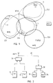
- Fig. 1 shows an embodiment of an MSC area or a location area of a cellular mobile radio network where the present invention may be applied.
- the geographic area covered by the cellular mobile radio network is divided in an essentially continuous manner into smaller radio areas, i.e. into radio cells CS1, CS2, CS3 and CS4, such that adjacent radio areas limit one another or overlap in their peripheral areas.
- each radio cell CS1 to CS4 is located at least one fixed radio station or base station BTS1 to BTS4 capable of establishing a connection on the radio channels allocated to it, i.e. pairs of transmitting and receiving frequencies (duplex interval e.g. 45 MHz), with the mobile radios MS currently located or roaming in its radio cells CS1 to CS4.
- Each base station BTS has also signalling and traffic channel links with a mobile exchange MSC, which controls the operation of one or more base stations within its MSC area.
- a mobile exchange MSC which controls the operation of one or more base stations within its MSC area.
- Each base station BTS1 to BTS4 of the cellular mobile radio network typically comprises at least one radio transmitter and one receiver; in the embodiment of Fig. 2, there are two radio transmitters 21 and 22 and two radio receivers 33 and 34 connected to an antenna unit ANT1.
- the size and shape of the radio coverage (radiation pattern) of the antenna unit ANT1 determine the size and shape of the radio cell of the base station.
- the antenna unit ANT1 may comprise separate antennae for transmitting and for receiving.
- radio transmitters 21 and 22 are connected directly to a combiner 24 combining the radio frequency transmission signals of the radio transmitters 21 and 22 and feeding the combined signal to the antenna unit ANT1.
- the antenna unit ANT1 is connected to radio receivers 33 and 34 via a distribution amplifier unit 32.
- the base station BTS has a fixed coverage area determined by the radiation patterns of one omnidirectional antenna or, alternatively, of one or more directional antennae. All the radio channels of the base station are within the coverage area of the main antenna unit ANT1, i.e. available to the mobile radios in the radio cell of the base station.
- the area covered by the cell CS4 may include the end of a motorway which is the main entry to the city and where traffic jams between 7.00 and 8.30 am.
- the area covered by another radio cell CS1 may include e.g. an industrial and office area where the most telephone traffic occurs between 8.30 and 16.00.
- the cell CS2 may cover an area including a sports stadium or a fair area and the capacity demand for telephone traffic is high when events are organized therein.
- the utilization of the radio channels is low at the system level.
- the system of the invention comprises at least one base station with an antenna / antennae directable, depending on the regional variation in traffic load, to the near-by areas currently requiring the most traffic capacity.
- the cells CS1, CS2 and CS4 have in their vicinity a base station BTS5 which has an antenna with a radiation pattern that can, if necessary, be directed to the directions 1, 2 and 3 to compensate and eliminate load peaks of telephone traffic in the cells at different times.
- Fig. 3 illustrates a few possible ways to control the directing of the radiation pattern of the antenna in the base station BTS5.
- the base station BTS5 is identical to the base stations BTS1 to BTS4 in its basic structure but, in addition, it includes a mechanical drive means 43 connected to a frame 45 (mast) for re-directing the directional antenna unit 44 (usually includes different antennae for transmitting and receiving) by turning the antenna unit.
- the drive means is, for example, a step-by-step controllable electric motor 43, which may turn the antenna unit 41 at least in a horizontal plane, advantageously also in a vertical plane. Vertical directability is advantageous e.g.
- the antenna unit when the antenna unit is located at a high location since the antenna unit can then be directed to a near-by area at a lower level by inclining the antenna towards the area in a vertical plane. Also the length of the antenna lobe (radiation pattern) may be affected by turning the antenna in a vertical plane.
- the antenna turning means 43 may be controlled in many ways, some of which are illustrated in Fig. 3.
- the directability of the antenna 44 in response to different times of the day and the corresponding control operations of the turning means 43 may be automatic and permanently programmed to a particular timer unit 42.
- the antenna of the base station BTS5 may be redirected automatically depending on the time of the day and / or the day of the week, e.g. such that from 7.00 to 8.30 am the antenna of the base station BTS5 assumes the direction 1 (motorway), from 8.30 to 16.00, the direction 2 (office and industrial area), and when events are arranged at the sports stadium, the direction 3.
- the turning means 43 of the antenna 44 may be controlled by remote control from the control center 41 of the radio system either manually or by preprogramming depending on the time and the loading of the network.
- the radio system may comprise a separate capacity control unit OMCRN, which, depending on the time and / or the loading of the system, automatically directs channel capacity to the loaded areas by controlling e.g. the antenna turning unit 43 of the base station BTS5.
- OMCRN separate capacity control unit
- the system may comprise one OMCRN unit for the entire system or several OMCRN units, each of which controls part of the system.
- An OMCRN unit also makes it possible to take into account the effect the directing of the antennae has on elsewhere in the radio network.
- An OMCRN unit or the corresponding operations may also be integrated to a mobile exchange MSC.
- a mobile exchange MSC may, on detecting overloading of a base station BTS1, generate an alarm to a capacity control unit OMCRN, whereby the OMCRN instructs the turning means 43 of the base station to turn the antenna 44 to the direction 2.
Landscapes
- Engineering & Computer Science (AREA)
- Computer Networks & Wireless Communication (AREA)
- Signal Processing (AREA)
- Mobile Radio Communication Systems (AREA)
- Radio Relay Systems (AREA)
- Radar Systems Or Details Thereof (AREA)
Abstract
Description
- The invention relates to a cellular radio system comprising a plurality of mobile radio stations roaming in the system, a plurality of base stations, each base station comprising at least one radio transmitter and radio receiver, an antenna means with a predetermined radio coverage area, and one or more allocated radio channels for establishing a radio connection with the mobile radio stations within the predetermined radio coverage area, at least the base stations with adjacent radio coverage areas having different allocated radio channels.
- In cellular mcbile radio networks the geographical area covered by the network is divided into radio cells, each of which has at least one base station. A certain number of frequencies (radio channels) are allocated to each base station, and said channels may in turn be shared by a plurality of TDMA (Time Division Multiple Access) traffic channels. The size and distribution of cells and the number of radio channels available to them are typically determined by the traffic capacity demand in said area. However, a cellular mobile radio network may include cells or larger areas where the traffic capacity demand may rise temporarily, e.g. at particular times of the day, to a very high level. If the number of radio channels in a cell is set on the basis of said instaneous maximum capacity demand, the number of radio channels increases, and consequently the amount and cost of radio equipment in a base station also becomes higher. Further, this kind of solution does not result in effective utilization of radio frequencies in a network. On the other hand, if the number of radio channels and the equipment of the base station are not set on the basis of maximum traffic, the number of failed call attempts becomes very high in said area at peak hours.
- The object of the invention is to overcome this problem.
- This is achieved by a cellular radio system according to the invention, the system comprising at least one base station including an antenna means that can be directed automatically or by remote control, depending on the time of the day or variation in regional traffic load.
- The basic idea of the invention is that at least one base station may, by mechanically re-directing its antenna according to traffic demand, direct part or all of its capacity (radio and / or traffic channels) to the area of the radio cell where the traffic capacity demand has temporarily increased. An advantage of the invention is that the number of channels in a single radio cell need not be set on the basis of an instantaneous maximum capacity demand in said radio cell but it can be set on the basis of an average maximum capacity demand in a plurality of adjacent radio cells. If necessary, the traffic capacity of a single cell may be increased by directing part of the capacity of the neighboring cells thereto, whereby the capacity of the network may be effectively controlled regionally and a higher utilization of the equipment and frequency / traffic channels of the base stations may be accomplished. Also, more effective utilization of radio channels in the entire network is achieved with the invention.
- This kind of base station with a directable antenna may also be a so-called extra base station which does not actually have a cell of its own and which is located at the peripheral area of a plurality of cells to selectively increase traffic capacity.
- Advantageously, a base station comprises a drive means for re-directing the antenna by turning it mechanically. This may be performed automatically or manually, remote controlled by an operator, from the control center of the system.
- EP-A- 0 416 872 relates to the routing of radiotelephone transmissions from a transmitter to a particular antenna in a cellular radiotelephone system.
- In the following the invention is described in greater detail by means of illustrating embodiments with reference to the attached drawings wherein
- Fig. 1 shows a schematic view of a cellular mobile radio network in accordance with the present invention;
- Fig. 2 shows a block diagram of a transmitter section and a receiver section of a base station according to the invention; and
- Fig. 3 shows ways of controlling the direction of a base station antenna.
- The invention may be applied to regional control of traffic capacity of a mobile radio network in any digital mobile telephone or mobile radio system, such as the European mobile telephone system GSM (Groupe Special Mobile), and in an analogue mobile telephone or radio system, such as the Nordic Mobile Telephone system NMT. With regard to the basic idea of the invention the analogue and digital systems are identical although in a typical analogue mobile radio system one frequency i.e. radio channel, provides one traffic channel, whereas in a typical digital mobile radio system the traffic capacity is higher since several, typically 8, traffic channels are time division multiplexed to each radio channel on a TDMA principle, i.e. on one radio channel may be up to 8 simultaneous connections between a base station and mobile radios. The basic configuration and operation of the GSM and NMT mobile phone systems are well known to those skilled in the art and defined fairly accurately by the specifications of each system.
- A mobile radio network may comprise one or more MSC areas, i.e. areas where services are provided by one mobile switching center MSC (mobile exchange). The MSC area may in turn consist of one or more location areas, which are areas covered by a plurality of radio cells. A cell is the smallest geographical area of the system, comprising one or more fixed radio transceivers or base transceiver stations BTS and utilizing predetermined radio channels.
- Fig. 1 shows an embodiment of an MSC area or a location area of a cellular mobile radio network where the present invention may be applied. The geographic area covered by the cellular mobile radio network is divided in an essentially continuous manner into smaller radio areas, i.e. into radio cells CS1, CS2, CS3 and CS4, such that adjacent radio areas limit one another or overlap in their peripheral areas. Accordingly, in each radio cell CS1 to CS4 is located at least one fixed radio station or base station BTS1 to BTS4 capable of establishing a connection on the radio channels allocated to it, i.e. pairs of transmitting and receiving frequencies (duplex interval e.g. 45 MHz), with the mobile radios MS currently located or roaming in its radio cells CS1 to CS4. It is typical that the radio channels allocated are different at least in adjacent radio cells. Each base station BTS has also signalling and traffic channel links with a mobile exchange MSC, which controls the operation of one or more base stations within its MSC area. For the sake of simplicity it is assumed in the embodiment of Fig. 1 that all base stations BTS1 to BTS4 have a common mobile exchange MSC.
- Each base station BTS1 to BTS4 of the cellular mobile radio network typically comprises at least one radio transmitter and one receiver; in the embodiment of Fig. 2, there are two
radio transmitters radio receivers - In the transmitter section of the base
station radio transmitters combiner 24 combining the radio frequency transmission signals of theradio transmitters - In the receiver section of the base station the antenna unit ANT1 is connected to
radio receivers distribution amplifier unit 32. - Normally the base station BTS has a fixed coverage area determined by the radiation patterns of one omnidirectional antenna or, alternatively, of one or more directional antennae. All the radio channels of the base station are within the coverage area of the main antenna unit ANT1, i.e. available to the mobile radios in the radio cell of the base station.
- However, situations occur where e.g. the traffic in the radio cell CS4 may temporarily exceed the capacity of the base station BTS4 of the cell. For example, the area covered by the cell CS4 may include the end of a motorway which is the main entry to the city and where traffic jams between 7.00 and 8.30 am. Correspondingly, the area covered by another radio cell CS1 may include e.g. an industrial and office area where the most telephone traffic occurs between 8.30 and 16.00. The cell CS2 may cover an area including a sports stadium or a fair area and the capacity demand for telephone traffic is high when events are organized therein.
- If the number of radio channels in the base stations BTS is determined in view of the peak hours, the utilization of the radio channels is low at the system level.
- The system of the invention comprises at least one base station with an antenna / antennae directable, depending on the regional variation in traffic load, to the near-by areas currently requiring the most traffic capacity. In the embodiment of Fig. 1 the cells CS1, CS2 and CS4 have in their vicinity a base station BTS5 which has an antenna with a radiation pattern that can, if necessary, be directed to the
directions - Fig. 3 illustrates a few possible ways to control the directing of the radiation pattern of the antenna in the base station BTS5. The base station BTS5 is identical to the base stations BTS1 to BTS4 in its basic structure but, in addition, it includes a mechanical drive means 43 connected to a frame 45 (mast) for re-directing the directional antenna unit 44 (usually includes different antennae for transmitting and receiving) by turning the antenna unit. The drive means is, for example, a step-by-step controllable
electric motor 43, which may turn theantenna unit 41 at least in a horizontal plane, advantageously also in a vertical plane. Vertical directability is advantageous e.g. when the antenna unit is located at a high location since the antenna unit can then be directed to a near-by area at a lower level by inclining the antenna towards the area in a vertical plane. Also the length of the antenna lobe (radiation pattern) may be affected by turning the antenna in a vertical plane. - The antenna turning means 43 may be controlled in many ways, some of which are illustrated in Fig. 3. The directability of the
antenna 44 in response to different times of the day and the corresponding control operations of theturning means 43 may be automatic and permanently programmed to aparticular timer unit 42. Thereby the antenna of the base station BTS5 may be redirected automatically depending on the time of the day and / or the day of the week, e.g. such that from 7.00 to 8.30 am the antenna of the base station BTS5 assumes the direction 1 (motorway), from 8.30 to 16.00, the direction 2 (office and industrial area), and when events are arranged at the sports stadium, thedirection 3. - Alternatively, the turning means 43 of the
antenna 44 may be controlled by remote control from thecontrol center 41 of the radio system either manually or by preprogramming depending on the time and the loading of the network. - Further, the radio system may comprise a separate capacity control unit OMCRN, which, depending on the time and / or the loading of the system, automatically directs channel capacity to the loaded areas by controlling e.g. the
antenna turning unit 43 of the base station BTS5. The system may comprise one OMCRN unit for the entire system or several OMCRN units, each of which controls part of the system. An OMCRN unit also makes it possible to take into account the effect the directing of the antennae has on elsewhere in the radio network. An OMCRN unit or the corresponding operations may also be integrated to a mobile exchange MSC. For example, a mobile exchange MSC (or another element in the network) may, on detecting overloading of a base station BTS1, generate an alarm to a capacity control unit OMCRN, whereby the OMCRN instructs the turning means 43 of the base station to turn theantenna 44 to thedirection 2. - The Figs. and the account thereof are intended only to illustrate the present invention. In its details the radio system according to the invention may vary within the scope of the attached claims.
Claims (6)
- A cellular radio system comprising a plurality of mobile radio stations roaming in the system, a plurality of base stations (BTS1-BTS4), each base station comprising at least one radio transmitter (21,22) and radio receiver (33,34), an antenna means (ANT1) with a predetermined radio coverage area (CS1-CS2), and one or more allocated radio channels for establishing a radio connection with the mobile radio stations (MS) within the predetermined radio coverage area (CS1-CS4), at least the base stations with adjacent radio coverage areas having different allocated radio channels, characterized in that the system comprises at least one base station (BTS5) including a directional antenna means (ANT1,44) having drive means (43) for mechanically turning the antenna means so as to redirect the radiation pattern of the antenna means automatically or by remote control, depending on the time of the day or variation in regional traffic load.
- A cellular radio system according to claim 1, characterized in that the antenna means is automatically directable in response to the time of the day and / or the day of the week.
- A cellular radio system according to claim 1, characterized in that the antenna means is directable automatically or manually to the nearby areas currently requiring the most traffic capacity.
- A cellular radio system according to claim 1, characterized in that the system comprises means (OMCRN) for re-directing the antenna means (44) on the basis of an overload alarm generated by an element in the system.
- A cellular radio system according to any one of the preceding claims, characterized in that the system is a digital cellular radio system and that each radio channel comprises a plurality of TDMA traffic channel time slots.
- A cellular radio system according to any one of claims 1 to 4, characterized in that the system is an analogue cellular radio system.
Applications Claiming Priority (3)
| Application Number | Priority Date | Filing Date | Title |
|---|---|---|---|
| FI915886 | 1991-12-13 | ||
| FI915886A FI90384C (en) | 1991-12-13 | 1991-12-13 | The cellular radio system |
| PCT/FI1992/000328 WO1993012587A1 (en) | 1991-12-13 | 1992-12-02 | Cellular radio system |
Publications (2)
| Publication Number | Publication Date |
|---|---|
| EP0616741A1 EP0616741A1 (en) | 1994-09-28 |
| EP0616741B1 true EP0616741B1 (en) | 1995-11-08 |
Family
ID=8533662
Family Applications (1)
| Application Number | Title | Priority Date | Filing Date |
|---|---|---|---|
| EP92924739A Expired - Lifetime EP0616741B1 (en) | 1991-12-13 | 1992-12-02 | Cellular radio system |
Country Status (8)
| Country | Link |
|---|---|
| EP (1) | EP0616741B1 (en) |
| JP (1) | JP3267971B2 (en) |
| AT (1) | ATE130141T1 (en) |
| AU (1) | AU665596B2 (en) |
| DE (1) | DE69205993T2 (en) |
| FI (1) | FI90384C (en) |
| NO (1) | NO303895B1 (en) |
| WO (1) | WO1993012587A1 (en) |
Cited By (2)
| Publication number | Priority date | Publication date | Assignee | Title |
|---|---|---|---|---|
| EP0789938A1 (en) | 1994-11-04 | 1997-08-20 | Deltec New Zealand Limited | An antenna control system |
| US6987487B2 (en) | 2001-02-19 | 2006-01-17 | Andrew Corporation | Antenna system |
Families Citing this family (10)
| Publication number | Priority date | Publication date | Assignee | Title |
|---|---|---|---|---|
| ZA95797B (en) * | 1994-02-14 | 1996-06-20 | Qualcomm Inc | Dynamic sectorization in a spread spectrum communication system |
| AU3260495A (en) * | 1995-08-31 | 1997-03-19 | Nokia Telecommunications Oy | A method of levelling a traffic load of a base station in a cellular radio system, and a cellular radio system |
| GB2315386B (en) * | 1996-07-13 | 2000-10-18 | Motorola Ltd | Improved flow control in cellular radio networks |
| FI109513B (en) * | 1997-05-13 | 2002-08-15 | Nokia Corp | Cell load based handover on mobile communication systems |
| IT1304083B1 (en) * | 1998-12-22 | 2001-03-07 | Italtel Spa | SYSTEM AND PROCEDURE FOR THE CONTROL OF THE ANTENNAS OF A RADIO MOBILE TELEPHONE |
| FR2806838B1 (en) * | 2000-03-27 | 2003-07-18 | Mitsubishi Electric Inf Tech | METHOD OF DYNAMICALLY TILTING ANTENNA FOR A RADIOTELECOMMUNICATION SYSTEM |
| GB2361385A (en) | 2000-04-12 | 2001-10-17 | Queen Mary & Westfield College | Intelligent control of radio resorces in a wireless network |
| FR2808160B1 (en) | 2000-04-21 | 2004-05-28 | Mitsubishi Electric Inf Tech | METHOD FOR DETERMINING THE POSITION OF A MOBILE STATION OF A MOBILE TELECOMMUNICATIONS NETWORK |
| GB2364478A (en) | 2000-06-30 | 2002-01-23 | Nokia Oy Ab | Cellular broadcast system responsive to distribution of demand |
| JP4595379B2 (en) * | 2004-04-30 | 2010-12-08 | 日本電気株式会社 | Mobile communication service system and method |
Family Cites Families (6)
| Publication number | Priority date | Publication date | Assignee | Title |
|---|---|---|---|---|
| DE3411014A1 (en) * | 1984-03-24 | 1985-09-26 | Standard Elektrik Lorenz Ag, 7000 Stuttgart | MESSAGE TRANSFER SYSTEM |
| US5048116A (en) * | 1989-05-24 | 1991-09-10 | Motorola, Inc. | Signal routing system |
| US5021801A (en) * | 1989-09-05 | 1991-06-04 | Motorola, Inc. | Antenna switching system |
| US5276907A (en) * | 1991-01-07 | 1994-01-04 | Motorola Inc. | Method and apparatus for dynamic distribution of a communication channel load in a cellular radio communication system |
| FI91344C (en) * | 1991-03-05 | 1994-06-10 | Nokia Telecommunications Oy | Cellular radio network, base station and method for regionally adjusting traffic capacity in a cellular radio network |
| US5212830A (en) * | 1991-05-31 | 1993-05-18 | International Mobile Machines Corporation | Radio frequency communications system |
-
1991
- 1991-12-13 FI FI915886A patent/FI90384C/en active
-
1992
- 1992-12-02 DE DE69205993T patent/DE69205993T2/en not_active Expired - Fee Related
- 1992-12-02 AU AU30879/92A patent/AU665596B2/en not_active Ceased
- 1992-12-02 EP EP92924739A patent/EP0616741B1/en not_active Expired - Lifetime
- 1992-12-02 WO PCT/FI1992/000328 patent/WO1993012587A1/en active IP Right Grant
- 1992-12-02 AT AT92924739T patent/ATE130141T1/en not_active IP Right Cessation
- 1992-12-02 JP JP51042793A patent/JP3267971B2/en not_active Expired - Fee Related
-
1994
- 1994-06-10 NO NO942190A patent/NO303895B1/en not_active IP Right Cessation
Cited By (3)
| Publication number | Priority date | Publication date | Assignee | Title |
|---|---|---|---|---|
| EP0789938A1 (en) | 1994-11-04 | 1997-08-20 | Deltec New Zealand Limited | An antenna control system |
| US8558739B2 (en) | 1994-11-04 | 2013-10-15 | Andrew Llc | Antenna control system |
| US6987487B2 (en) | 2001-02-19 | 2006-01-17 | Andrew Corporation | Antenna system |
Also Published As
| Publication number | Publication date |
|---|---|
| WO1993012587A1 (en) | 1993-06-24 |
| JPH07501914A (en) | 1995-02-23 |
| NO942190D0 (en) | 1994-06-10 |
| FI90384C (en) | 1994-01-25 |
| DE69205993T2 (en) | 1996-04-11 |
| EP0616741A1 (en) | 1994-09-28 |
| AU665596B2 (en) | 1996-01-11 |
| DE69205993D1 (en) | 1995-12-14 |
| FI915886A0 (en) | 1991-12-13 |
| NO942190L (en) | 1994-08-10 |
| JP3267971B2 (en) | 2002-03-25 |
| ATE130141T1 (en) | 1995-11-15 |
| AU3087992A (en) | 1993-07-19 |
| FI915886A (en) | 1993-06-14 |
| FI90384B (en) | 1993-10-15 |
| NO303895B1 (en) | 1998-09-14 |
Similar Documents
| Publication | Publication Date | Title |
|---|---|---|
| US5805996A (en) | Base station with antenna coverage directed into neighboring cells based on traffic load | |
| EP0574454B1 (en) | A cellular radio network, a base station and a method for controlling local traffic capacity in the cellular radio network | |
| US6246674B1 (en) | Antenna deployment sector cell shaping system and method | |
| US5889494A (en) | Antenna deployment sector cell shaping system and method | |
| US6205337B1 (en) | Use of sectorized polarization diversity as a means of increasing capacity in cellular wireless systems | |
| EP0531090B1 (en) | Cells re-use partition in a mobile communication system | |
| US5432780A (en) | High capacity sectorized cellular communication system | |
| US5887261A (en) | Method and apparatus for a radio remote repeater in a digital cellular radio communication system | |
| EP0647982A2 (en) | Base station antenna arrangement | |
| EP0616741B1 (en) | Cellular radio system | |
| EP0359535B1 (en) | High capacity sectorized cellular communication system | |
| JPH11502378A (en) | Beam antenna system | |
| KR20070074564A (en) | Method for flexible surpoting non-symmetrical service in multi-carrier tdd mobile communication system | |
| GB2281007A (en) | Base station antenna arrangement | |
| US6212385B1 (en) | Cellular communication system and re-use pattern therefor | |
| EP1169875B1 (en) | Adaptive sectorization | |
| EP0813310A1 (en) | Method and arrangement relating to signal transmission | |
| CA2133111C (en) | Method and apparatus for a radio remote repeater in a digital cellular radio communication system | |
| KR100485767B1 (en) | A operating method and a control device of sector antenna for bts | |
| EP0867100B1 (en) | Cellular communication system and re-use pattern therefor | |
| WO2001031941A1 (en) | Method and apparatus for providing forward link softer handoff in a code division multiple access communication system | |
| CA1336519C (en) | High capacity sectorized cellular communication system | |
| KR20010038978A (en) | Unity base station apparatus of communication system | |
| IE69267B1 (en) | High capacity sectorized cellular communication system |
Legal Events
| Date | Code | Title | Description |
|---|---|---|---|
| PUAI | Public reference made under article 153(3) epc to a published international application that has entered the european phase |
Free format text: ORIGINAL CODE: 0009012 |
|
| 17P | Request for examination filed |
Effective date: 19940616 |
|
| AK | Designated contracting states |
Kind code of ref document: A1 Designated state(s): AT BE CH DE DK ES FR GB GR IE IT LI LU MC NL PT SE |
|
| 17Q | First examination report despatched |
Effective date: 19950131 |
|
| GRAA | (expected) grant |
Free format text: ORIGINAL CODE: 0009210 |
|
| AK | Designated contracting states |
Kind code of ref document: B1 Designated state(s): AT BE CH DE DK ES FR GB GR IE IT LI LU MC NL PT SE |
|
| PG25 | Lapsed in a contracting state [announced via postgrant information from national office to epo] |
Ref country code: MC Free format text: LAPSE BECAUSE OF NON-PAYMENT OF DUE FEES Effective date: 19951108 Ref country code: GR Free format text: LAPSE BECAUSE OF FAILURE TO SUBMIT A TRANSLATION OF THE DESCRIPTION OR TO PAY THE FEE WITHIN THE PRESCRIBED TIME-LIMIT Effective date: 19951108 Ref country code: ES Free format text: THE PATENT HAS BEEN ANNULLED BY A DECISION OF A NATIONAL AUTHORITY Effective date: 19951108 Ref country code: DK Effective date: 19951108 |
|
| REF | Corresponds to: |
Ref document number: 130141 Country of ref document: AT Date of ref document: 19951115 Kind code of ref document: T |
|
| REG | Reference to a national code |
Ref country code: IE Ref legal event code: FG4D Free format text: 66078 |
|
| REF | Corresponds to: |
Ref document number: 69205993 Country of ref document: DE Date of ref document: 19951214 |
|
| ET | Fr: translation filed | ||
| ITF | It: translation for a ep patent filed |
Owner name: BARZANO'E ZANARDO S.P.A. |
|
| PG25 | Lapsed in a contracting state [announced via postgrant information from national office to epo] |
Ref country code: LU Free format text: LAPSE BECAUSE OF NON-PAYMENT OF DUE FEES Effective date: 19951231 Ref country code: IE Free format text: LAPSE BECAUSE OF NON-PAYMENT OF DUE FEES Effective date: 19951231 |
|
| REG | Reference to a national code |
Ref country code: CH Ref legal event code: NV Representative=s name: ICB INGENIEURS CONSEILS EN BREVETS SA |
|
| PLBE | No opposition filed within time limit |
Free format text: ORIGINAL CODE: 0009261 |
|
| STAA | Information on the status of an ep patent application or granted ep patent |
Free format text: STATUS: NO OPPOSITION FILED WITHIN TIME LIMIT |
|
| 26N | No opposition filed | ||
| NLR4 | Nl: receipt of corrected translation in the netherlands language at the initiative of the proprietor of the patent | ||
| PGFP | Annual fee paid to national office [announced via postgrant information from national office to epo] |
Ref country code: SE Payment date: 20011206 Year of fee payment: 10 |
|
| PGFP | Annual fee paid to national office [announced via postgrant information from national office to epo] |
Ref country code: AT Payment date: 20011212 Year of fee payment: 10 |
|
| PGFP | Annual fee paid to national office [announced via postgrant information from national office to epo] |
Ref country code: CH Payment date: 20011214 Year of fee payment: 10 |
|
| PGFP | Annual fee paid to national office [announced via postgrant information from national office to epo] |
Ref country code: NL Payment date: 20011228 Year of fee payment: 10 |
|
| REG | Reference to a national code |
Ref country code: GB Ref legal event code: IF02 |
|
| REG | Reference to a national code |
Ref country code: GB Ref legal event code: 732E |
|
| PG25 | Lapsed in a contracting state [announced via postgrant information from national office to epo] |
Ref country code: AT Free format text: LAPSE BECAUSE OF NON-PAYMENT OF DUE FEES Effective date: 20021202 |
|
| PG25 | Lapsed in a contracting state [announced via postgrant information from national office to epo] |
Ref country code: SE Free format text: LAPSE BECAUSE OF NON-PAYMENT OF DUE FEES Effective date: 20021203 |
|
| PGFP | Annual fee paid to national office [announced via postgrant information from national office to epo] |
Ref country code: FR Payment date: 20021210 Year of fee payment: 11 |
|
| PG25 | Lapsed in a contracting state [announced via postgrant information from national office to epo] |
Ref country code: LI Free format text: LAPSE BECAUSE OF NON-PAYMENT OF DUE FEES Effective date: 20021231 Ref country code: CH Free format text: LAPSE BECAUSE OF NON-PAYMENT OF DUE FEES Effective date: 20021231 |
|
| PGFP | Annual fee paid to national office [announced via postgrant information from national office to epo] |
Ref country code: BE Payment date: 20030218 Year of fee payment: 11 |
|
| PG25 | Lapsed in a contracting state [announced via postgrant information from national office to epo] |
Ref country code: NL Free format text: LAPSE BECAUSE OF NON-PAYMENT OF DUE FEES Effective date: 20030701 |
|
| EUG | Se: european patent has lapsed | ||
| REG | Reference to a national code |
Ref country code: CH Ref legal event code: PL |
|
| NLV4 | Nl: lapsed or anulled due to non-payment of the annual fee |
Effective date: 20030701 |
|
| PGFP | Annual fee paid to national office [announced via postgrant information from national office to epo] |
Ref country code: GB Payment date: 20031126 Year of fee payment: 12 |
|
| PGFP | Annual fee paid to national office [announced via postgrant information from national office to epo] |
Ref country code: DE Payment date: 20031211 Year of fee payment: 12 |
|
| PG25 | Lapsed in a contracting state [announced via postgrant information from national office to epo] |
Ref country code: BE Free format text: LAPSE BECAUSE OF NON-PAYMENT OF DUE FEES Effective date: 20031231 |
|
| BERE | Be: lapsed |
Owner name: *NOKIA TELECOMMUNICATIONS OY Effective date: 20031231 |
|
| PG25 | Lapsed in a contracting state [announced via postgrant information from national office to epo] |
Ref country code: FR Free format text: LAPSE BECAUSE OF NON-PAYMENT OF DUE FEES Effective date: 20040831 |
|
| REG | Reference to a national code |
Ref country code: FR Ref legal event code: ST |
|
| PG25 | Lapsed in a contracting state [announced via postgrant information from national office to epo] |
Ref country code: GB Free format text: LAPSE BECAUSE OF NON-PAYMENT OF DUE FEES Effective date: 20041202 |
|
| PG25 | Lapsed in a contracting state [announced via postgrant information from national office to epo] |
Ref country code: DE Free format text: LAPSE BECAUSE OF NON-PAYMENT OF DUE FEES Effective date: 20050701 |
|
| GBPC | Gb: european patent ceased through non-payment of renewal fee |
Effective date: 20041202 |
|
| PG25 | Lapsed in a contracting state [announced via postgrant information from national office to epo] |
Ref country code: IT Free format text: LAPSE BECAUSE OF NON-PAYMENT OF DUE FEES;WARNING: LAPSES OF ITALIAN PATENTS WITH EFFECTIVE DATE BEFORE 2007 MAY HAVE OCCURRED AT ANY TIME BEFORE 2007. THE CORRECT EFFECTIVE DATE MAY BE DIFFERENT FROM THE ONE RECORDED. Effective date: 20051202 |
|
| PG25 | Lapsed in a contracting state [announced via postgrant information from national office to epo] |
Ref country code: PT Free format text: LAPSE BECAUSE OF NON-PAYMENT OF DUE FEES Effective date: 19960408 |