EP0618461A2 - Distance measuring method and apparatus - Google Patents
Distance measuring method and apparatus Download PDFInfo
- Publication number
- EP0618461A2 EP0618461A2 EP94400489A EP94400489A EP0618461A2 EP 0618461 A2 EP0618461 A2 EP 0618461A2 EP 94400489 A EP94400489 A EP 94400489A EP 94400489 A EP94400489 A EP 94400489A EP 0618461 A2 EP0618461 A2 EP 0618461A2
- Authority
- EP
- European Patent Office
- Prior art keywords
- scanning mirror
- angle
- plane
- image pickup
- slit light
- Prior art date
- Legal status (The legal status is an assumption and is not a legal conclusion. Google has not performed a legal analysis and makes no representation as to the accuracy of the status listed.)
- Granted
Links
Images
Classifications
-
- G—PHYSICS
- G01—MEASURING; TESTING
- G01S—RADIO DIRECTION-FINDING; RADIO NAVIGATION; DETERMINING DISTANCE OR VELOCITY BY USE OF RADIO WAVES; LOCATING OR PRESENCE-DETECTING BY USE OF THE REFLECTION OR RERADIATION OF RADIO WAVES; ANALOGOUS ARRANGEMENTS USING OTHER WAVES
- G01S17/00—Systems using the reflection or reradiation of electromagnetic waves other than radio waves, e.g. lidar systems
- G01S17/88—Lidar systems specially adapted for specific applications
- G01S17/89—Lidar systems specially adapted for specific applications for mapping or imaging
-
- G—PHYSICS
- G01—MEASURING; TESTING
- G01S—RADIO DIRECTION-FINDING; RADIO NAVIGATION; DETERMINING DISTANCE OR VELOCITY BY USE OF RADIO WAVES; LOCATING OR PRESENCE-DETECTING BY USE OF THE REFLECTION OR RERADIATION OF RADIO WAVES; ANALOGOUS ARRANGEMENTS USING OTHER WAVES
- G01S17/00—Systems using the reflection or reradiation of electromagnetic waves other than radio waves, e.g. lidar systems
- G01S17/02—Systems using the reflection of electromagnetic waves other than radio waves
- G01S17/06—Systems determining position data of a target
- G01S17/46—Indirect determination of position data
Abstract

Description
- The present invention relates to a method and an apparatus for measuring a distance and, more particularly, for measuring the external shape of a three-dimensional object.
- According to one of the distance measuring methods known heretofore, positions on the surface of a three-dimensional object are measured by scanning the surface with a beam of slit light while rotating a scanning mirror, and detecting the points in time when the slit light reflected from the object surface passes through sensing cells arranged on an image pickup plane.
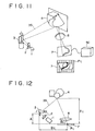
- Fig. 11 shows an exemplary conventional apparatus which carries out such distance measuring method. In this example, an infrared or similar laser beam emitted from a laser light source 1 is formed into slit light via an
optical device 2. The slit laser light is then reflected by ascanning mirror 3 consisting of a galvano mirror or the like disposed at a predetermined position. Theslit light 3S thus reflected from thescanning mirror 3 scans the surface of a three-dimensional object 4, which is to be measured, with rotation of themirror 3. - The slit light reflected from the
object 4 is focused on animage pickup plane 7 via anoptical device 6. In acontroller 5C comprising a differentiator, an integrator and other components, the rotational position of thescanning mirror 3 is detected by finding the point in time when the slit light reflected from theobject 4 passes through each of the image sensing cells, i.e., light receiving cells Pi,j arranged two-dimensionally on theimage pickup plane 7. The distance up to theobject 4 is measured trigonometrically per sensing cell Pi,j on theimage pickup plane 7 from the positional relationship among the rotational position of thescanning mirror 3, theimage pickup plane 7 and thescanning mirror 3. - Fig. 12 schematically shows the principle of measuring three-dimensional coordinate positions on the surface of the
object 4 according to the method of triangulation, The distance Zi,j, from theimage pickup plane 7 to one surface position on theobject 4 whose reflected slit light is focused on the sensing cell Pi,j of theimage pickup plane 7 can be obtained trigonometrically from Eq. (1) by using the distance Bi,j between the focused position on theimage pickup plane 7 and the rotational center of thescanning mirror 3, the angle αi,j formed by theimage pickup plane 7 and the slit light reflected 3S from themirror 3, the angle βi,j at which the slit light is incident upon theimage pickup plane 7 from theobject 4, and the vertical distance A from the rotational center of thescanning mirror 3 to an extension of theimage pickup plane 7.
- The three parameters Bi,j, βi,j and A in Eq. (1) are constants determined uniquely by the arrangement of the light source 1, the
optical device 2, thescanning mirror 3, theoptical device 6 and theimage pickup plane 7. The angle αi,j formed by theimage pickup plane 7 and the slit light reflected 3S from thescanning mirror 3 can be obtained by, as mentioned, detecting the rotational position of themirror 3 from the point in time when the slit light reflected from theobject 4 passes through the sensing cell Pi,j on theimage pickup plane 7. Therefore it is possible to trigonometrically calculate the distance Zi,j from each cell on theimage pickup plane 7 to theobject 4. - However, the following problems exist in the conventional distance measuring method and apparatus mentioned above.
- For accurately finding the distance Zi,j up to the
object 4, it is necessary to derive the four parameters Bi,j, βi,j, A and αi,j with high precision. However, since the parameter αi,j represents the angle formed by a plane parallel with theimage pickup plane 7 and the slit light reflected from thescanning mirror 3, it is difficult to derive the parameter αi,j with high precision even by accurately finding the point in time when the slit light reflected from theobject 4 passes through the sensing cell Pi,j on theimage pickup plane 7. Extremely great difficulties are also unavoidable in measuring the parameters Bi,j, βi,j and A with high precision. - Even if the four parameters Bi,j, βi,j, A and αi,j can be obtained precisely, a long time is required for measuring one distance image because a considerably long time is needed to execute the calculation of Eq. (1) for every one of the sensing cells Pi,j on the
image pickup plane 7. - The present invention has been accomplished in view of the circumstances described above. An object of the invention is to provide an improved distance measuring method and apparatus capable of performing accurate and fast measurements of positions on the surface of a three-dimensional object.
- According to a first aspect of the present invention, a distance measuring method scans the surface of an object with slit light while rotating a scanning mirror (e.g.,
mirror 3 in Fig. 1), and then detects the points in time when the slit light reflected from the object passes through sensing cells (e.g., cells Pi,j in Fig. 1) arranged on an image pickup plane (e.g.,plane 7 in Fig. 1), thereby measuring the positions on the surface of the object. This method comprises the steps of: calculating a numerical value (e.g., count value C₁ in an undermentioned embodiment) indicative of a first angle difference (e.g., angle ϑ₁ in Fig. 2) between a first angle (e.g., angle ϑS0 in Fig. 1) of the scanning mirror, where slit light reflected from a reference plane at a first position (e.g., position S0 in Fig. 1) is incident upon a predetermined one of the sensing cells arranged on the image pickup plane, and a second angle (e.g., angle ϑS1 in Fig. 1) of the scanning mirror, where slit light reflected from the reference plane at a second position (e.g., position Sl in Fig. 1) is incident upon the sensing cell on the image pickup plane, the second position of the reference plane being spaced apart by a predetermined distance (e.g., d in Fig. 1) from the first position; calculating a numerical value (e.g., count value C₂ in the embodiment) indicative of a second angle difference (e.g., angle ϑ₂ in Fig. 2) between the second angle (e.g., ϑS1 in Fig. 1) of the scanning mirror, and a third angle (e.g., angle ϑS2 in Fig. 1) of the scanning mirror, where slit light reflected from the reference plane at a third position (e.g., position S2 in Fig. 1) is incident upon the sensing cell on the image pickup plane, the third position of the reference plane being spaced apart from the second position by the same predetermined distance; calculating a numerical value (e.g., count value Cx in the embodiment) indicative of a third angle difference (e.g., angle ϑx in Fig. 2) between the third angle (e.g., angle ϑS2 in Fig. 1) of the scanning mirror and a fourth angle of the scanning mirror where slit light reflected from the surface of the object to be measured is incident upon the sensing cell on the image pickup plane; and calculating the distance between the object and the first position on the basis of the three numerical values indicative of the first, second and third angle differences. - According to a second aspect of the invention, there is provided a distance measuring method which scans the surface of an object with slit light while rotating a scanning mirror, and then detects the points in time when the slit light reflected from the object passes through sensing cells arranged on an image pickup plane, thereby measuring the positions on the surface of the object. This method comprises the steps of: calculating a count value C₁ indicative of a first angle difference between a first angle of the scanning mirror, where slit light reflected from a reference plane at a first position is incident upon a predetermined one out of a plurality of sensing cells arranged on an image pickup plane, and a second angle of the scanning mirror, where slit light reflected from the reference plane at a second position is incident upon the one sensing cell on the image pickup plane, the second position of the reference plane being spaced apart from the first position by a predetermined distance; calculating a count value C₂ indicative of a second angle difference between the second angle of the scanning mirror and a third angle of the scanning mirror, where slit light reflected from the reference plane at a third position is incident upon the one sensing cell on the image pickup plane, the third position of the reference plane being spaced apart by the same predetermined distance from the second position; calculating a count value Cx indicative of a third angle difference between the third angle of the scanning mirror and a fourth angle of the scanning mirror, where slit light reflected from the surface of the object to be measured is incident upon the one sensing cell on the image pickup plane; calculating a parameter k representing the relationship between the rotational angle of the scanning mirror and the count value; and calculating the distance x from the first position to the object by Eq. (2) given below:

- According to a third aspect of the invention, a distance measuring apparatus scans the surface of an object with slit light while rotating a scanning mirror, and then detects the points in time when the slit light reflected from the object passes through sensing cells arranged on an image pickup plane, thereby measuring the positions on the surface of the object. This apparatus comprises a counter (e.g.,
counter 12 in Figs. 3 and 4) for outputting a count value indicative of the rotational angle of the scanning mirror; a first subtracter (e.g., subtracter 142A in Fig. 4) for calculating the difference between the output count value of the counter indicative of the first angle of the scanning mirror, where slit light reflected from a reference plane at a first position is incident upon a predetermined one out of a plurality of sensing cells arranged on the image pickup plane, and the output count value of the counter indicative of a second angle of the scanning mirror, where slit light reflected from the reference plane at a second position is incident upon the one sensing cell on the image pickup plane, the second position of the reference plane being spaced apart from the first position by a predetermined distance; a second subtracter (e.g., subtracter 142B in Fig. 4) for calculating the difference between the output count value of the counter indicative of the second angle of the scanning mirror and the output count value of the counter indicative of a third angle of the scanning mirror, where slit light reflected from the reference plane at a third position is incident upon the one sensing cell on the image pickup plane, the third position of the reference plane being spaced apart from the second position by the same predetermined distance; a third subtracter (e.g., subtracter 142C in Fig. 4) for calculating the difference between the output count value of the counter indicative of the third angle of the scanning mirror and the output count value of the counter indicative of a fourth angle of the scanning mirror, where slit light reflected from the surface of the object to be measured is incident upon the one sensing cell on the image pickup plane; and a calculator (e.g.,calculator 143 in Fig. 4) for calculating the distance between the object and the first position on the basis of the outputs of the first, second, and third subtracters and the parameters representing the relationship between the rotational angles of the scanning mirror and the output count values of the counter. - According to a fourth aspect of the invention, a distance measuring apparatus scans the surface of an object with slit light while rotating a scanning mirror, and then detects the points in time when the slight light reflected from the object passes through sensing cells arranged on an image pickup plane, thereby measuring the positions on the surface of the object. This apparatus comprises a counter (e.g.,
counter 12 in Figs. 3 and 4) for outputting a count value indicative of the rotation angle of the scanning mirror; a subtracter (e.g., subtracter 142C in Fig. 4) for calculating the difference between the output count value of the counter indicative of the angle of the scanning mirror, where slit light reflected from a reference plane at a position (e.g., position S2 in Fig. 1) spaced apart by a predetermined distance from a first position is incident upon a predetermined one of the sensing cells on the image pickup plane, and the output count value of the counter indicative of the angle of the scanning mirror, where slit light reflected from the surface of the object to be measured is incident upon the sensing cell on the image pickup plane; and a lookup table (e.g., table in Fig. 5 or 6) for outputting the distance between the object and the first position in accordance with at least the output of the subtracter. - As a result of carrying out the present invention, the following advantageous effects are achievable.
- In the distance measuring method of the first aspect, the distance to the object can be measured fast with high precision due to the procedure of calculating a numerical value indicative of a first angle difference between the first angle of the scanning mirror, where the slit light reflected from the reference plane at a first position is incident upon a predetermined one of the sensing cells arranged on the image pickup plane, and the second angle of the scanning mirror, where the slit light reflected from the reference plane at a second position is incident upon the sensing cell on the image pickup plane, the second position of the reference plane being spaced apart from the first position by a predetermined distance; calculating a numerical value indicative of a second angle difference between the second angle of the scanning mirror and a third angle of the scanning mirror, where the slit light reflected from the reference plane at a third position is incident upon the sensing cell on the image pickup plane, the third position of the reference plane being spaced apart from the second position by the same predetermined distance; calculating a numerical value indicative of a third angle difference between the third angle of the scanning mirror and a fourth angle of the scanning mirror, where the slit light reflected from the surface of the object to be measured is incident upon the sensing cell on the image pickup plane; and calculating the distance between the object and the first position on the basis of the three numerical values indicative of the first, second and third angle differences.
- In the distance measuring method of the second aspect, the distance to the object can be measured fast with high precision due to the procedure of calculating a count value C₁ indicative of a first angle difference between a first angle of the scanning mirror, where the slit light reflected from a reference plane at a first position is incident upon a predetermined one of sensing cells arranged on an image pickup plane, and a second angle of the scanning mirror, where the slit light reflected from the reference plane at a second position is incident upon the sensing cell on the image pickup plane, the second position of the reference plane being spaced apart from the first position by a predetermined distance; calculating a count value C₂ indicative of a second angle difference between the second angle of the scanning mirror and a third angle of the scanning mirror, where the slit light reflected from the reference plane at a third position is incident upon the sensing cell on the image pickup plane, the third position of the reference plane being spaced apart from the second position thereof by the same predetermined distance; calculating a count value Cx indicative of a third angle difference between the third angle of the scanning mirror and a fourth angle of the scanning mirror, where the slit light reflected from the surface of the object to be measured is incident upon the sensing cell on the image pickup plane; calculating a parameter k representing of the relationship between the rotational angle of the scanning mirror and the count value; and calculating the distance x from the first position to the object by Eq. (2).
- In the distance measuring apparatus of the third aspect, the distance to the object can be measured fast with high precision due to the constitution which comprises a counter for outputting a count value indicative of the rotational angle of the scanning mirror, a first subtracter for calculating the difference between the output count value of the counter indicative of the first angle of the scanning mirror, where the slit light reflected from a reference plane at a first position is incident upon a predetermined one of the sensing cells arranged on the image pickup plane, and the output count value of the counter indicative of the second angle of the scanning mirror, where the slit light reflected from the reference plane at a second position is incident upon the sensing cell on the image pickup plane, the second position of the reference plane being spaced apart from the first position thereof by a predetermined distance; a second subtracter for calculating the difference between the output count value of the counter indicative of the second angle of the scanning mirror and the output count value of the counter indicative of a third angle of the scanning mirror, where the slit light reflected from the reference plane at a third position is incident upon the sensing cell on the image pickup plane, the third position of the reference plane being spaced apart from the second position by the same predetermined distance; a third subtracter for calculating the difference between the output count value of the counter indicative of the third angle of the scanning mirror and the output count value of the counter indicative of a fourth angle of the scanning mirror, where the slit light reflected from the surface of the object to be measured is incident upon the sensing cell on the image pickup plane; and a calculator for calculating the distance between the object and the first position on the basis of the outputs of the first, second, and third subtracters and the parameters representing the relationship between the rotational angles of the scanning mirror and the output count values of the counter.
- In the distance measuring apparatus of the fourth aspect, the distance to the object can be measured fast with high precision due to the constitution which comprises a counter for outputting a count value indicative of the rotational angle of the scanning mirror; a subtracter for calculating the difference between the output count value of the counter indicative of the angle of the scanning mirror, where the slit light reflected from a reference plane at a position spaced apart by a predetermined distance from a first position is incident upon a predetermined one of the sensing cells on the image pickup plane, and the output count value of the counter indicative of the angle of the scanning mirror, where the slit light reflected from the surface of the object to be measured is incident upon the sensing cell on the image pickup plane; and a lookup table for outputting the distance between the object and the first position in accordance with at least the output of the subtracter. The above and other features and advantages of the present invention will become apparent from the following description which will be given with reference to the illustrative accompanying drawings.
-
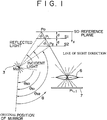
- Fig. 1 is a schematic diagram for explaining the principle of operation adopted in the distance measuring method and apparatus of the present invention;
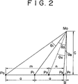
- Fig. 2 shows the details of the partial geometric relationship in Fig. 1;
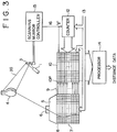
- Fig. 3 is a block diagram showing the constitution of a preferred embodiment which represents the distance measuring apparatus of the invention;
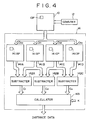
- Fig. 4 is a block diagram showing an exemplary constitution of a
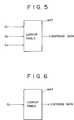
processor 14 employed in the apparatus of Fig. 3; - Fig. 5 is a block diagram of an exemplary lookup table usable instead of a
calculator 143 in Fig. 4; - Fig. 6 is a block diagram of a modification of the lookup table in Fig. 5;
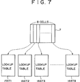
- Fig. 7 shows the relationship between an
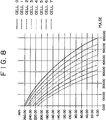
image pickup plane 7 and lookup tables; - Fig. 8 graphically shows an example of storage contents in the lookup tables 144Tl to 144T8 in Fig. 7;
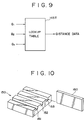
- Fig. 9 is a block diagram of another modification of the lookup table in Fig. 5;
- Fig. 10 is a perspective view of an exemplary position setting jig employed for positioning a reference plane;
- Fig. 11 is a perspective view of a conventional distance measuring apparatus known in the prior art; and
- Fig. 12 is a schematic diagram for explaining the method of triangulation employed in the conventional apparatus of Fig. 1.
- Hereinafter the present invention will be described in detail with reference to the accompanying drawings which represent preferred embodiments of the invention.
- Fig. 1 illustrates the principle operation adopted in the distance measuring method and apparatus of the invention and Fig. 2 shows the details of the partial geometric relationship in Fig. 1. The following description will be given with regard to an exemplary case of measuring the distance from a first plane position S0 to the surface of an object to be measured. Initially, a point in time is detected when slit light reflected from a reference plane set at the first plane position S0 is incident upon (i.e., passed through) each of sensing cells arrayed on an
image pickup plane 7. Next, a point in time is detected when slit light reflected from the reference plane at a second plane position S1, which is spaced apart by a predetermined distance d from the first plane position S0 and is in parallel therewith, is incident upon each sensing cell on the image pickup plane. Subsequently, another point in time is detected when slit light reflected from the reference plane at a third plane position S2, which is spaced apart the same predetermined distance d from the second plane position S1, is incident upon each sensing cell on theimage pickup plane 7. - A
scanning mirror 3 is rotated around a center point M₀ at a constant velocity, and an angle ϑε from the original position of the rotatingmirror 3 is given by Eq. (3) on the basis of a counter output value Cε which is reset at the original position.
(where k is a constant) - The image sensing (light receiving) cells Pi,j are arranged two-dimensionally on the
image pickup plane 7, and each cell has a specific line of sight direction dependent on anoptical device 6, which may be a lens. In this example, the distance from the reference plane at the first plane position S0 is measured to a point on the surface of the object which intersects the line of sight direction of each cell. - Suppose now that P₀, P₁ and P₂ denote the points where the line of sight direction of one sensing cell Pi,j on the
image pickup plane 7 intersects the reference plane set at the first, second and third plane positions S0, S1 and S3. Angles ϑS0, ϑS1 and ϑS2 denote the angles from the original position of thescanning mirror 3 when the slit light is incident upon such points P₀, P₁ and P₂ respectively. Then the relationship between the distance a from point P₀ to P₁ and the distance a from point P₁ to P₂ is expressed as Eq. (4).
(where s is a constant) - The angle ϑ₁ formed by segments P₀M₀ and M₀P₁, and the angle ϑ₂ formed by segments P₁M₀ and M₀P₂ are expressed as Eqs. (5) and (6), respectively.


- In the condition where a perpendicular line drawn in the line of sight direction from the rotational center M₀ of the
scanning mirror 3 intersects the extension of the segment P₀P₂ at a point Pf, the angle ϑB is given by Eq. (7) shown below.
- Supposing that Px denotes the target position on the object which is on a straight line P₀P₂ and is at a distance m from the point P₀, the angle ϑx is given by Eq. (8) as follows.

- Then the distance x up to the target position Px from the reference plane at the first plane position S0 thereof can be expressed as Eq. (9) from Eq. (4).

- Eqs. (10), (11) and (12) represent the relationship between the length B of the segment P₂Pf and the length C of the segment M₀Pf.


Eq. (13) is obtained from Eqs. (10), (11) and (12).
- From Eqs. (12) and (13), tanϑB can be expressed as Eq. (14) shown below.

- The length n from the point Px to P₂, and the length m from the point Px to P₁, can be expressed as Eqs. (15) and (16) on the basis of Eqs. (13) and (14), respectively.


- Accordingly, the distance x from the reference plane at the first plane position S0 to the target point Px on the surface of the object being measured is expressed as Eq. (17) on the basis of Eqs. (3), (4), (9) and (16).

- In Eq. (17), the count value C₁ indicates the angle difference ϑ₁ between the angle ϑS0 of the
scanning mirror 3, where the slit light reflected from the reference plane at the first plane position S0 is incident upon the sensing cell Pi,j on the image pickup plane, and the angle ϑS1 of thescanning mirror 3, where the slit light reflected from the reference plane at the second plane position Sl, which is spaced apart by a predetermined distance d from the first plane position S0, is incident upon the sensing cell Pi,j on theimage pickup plane 7. The count value C₂ indicates the angle difference ϑ₂ between the angle ϑS1 of thescanning mirror 3 and the angle ϑS2 of thescanning mirror 3, where the slit light reflected from the reference plane at the third plane position S2, which is spaced apart from the second plane position S1 by the same distance d, is incident upon the sensing cell Pi,j on theimage pickup plane 7. Meanwhile the count value Cx indicates the angle ϑx which is the difference between the angle ϑS2 of thescanning mirror 3 and the angle ϑSx of thescanning mirror 3, where the slit light reflected from the surface of the object is incident upon the sensing cell Pi,j on theimage pickup plane 7. - The parameter k, representing the relationship between the rotational angle of the
scanning mirror 3 and the count value, can be obtained from Eq. (17) under the condition where the reference plane is set at the previously known position other than the aforementioned first, second and third plane positions S0, Sl and S2. - Fig. 3 shows a preferred embodiment of the distance measuring apparatus according to the present invention. In this diagram, slit light 3S emitted from a slit light generating laser 1 is reflected via a
scanning mirror 3 consisting of, for example, a galvano mirror so that theslit light 3S is sequentially scanned by a reference plane set at a second position Sl in Fig. 1. Subsequently a reference plane set at a third plane position S2 in Fig. 1, and finally a three-dimensional object 4 to be measured. The slit light generating laser 1 may consist of a semiconductor laser which produces an output beam of 670 nm in wavelength (10mW at the outside of a lens, and approximately 1 mm in slit-light width). Practically anoptical device 2 for forming the output beam of the light source 1 into a slit is also provided in the actual apparatus, but suchoptical device 2 is not shown in Fig. 3 for the purpose of simplifying the illustration. - The slit light reflected sequentially from the reference plane at the first plane position S0 in Fig. 1, the reference plane at the second plane position Sl in Fig. 1, the reference plane at the third plane position S2 in Fig. 1 and the surface of the
object 4 is projected successively onto animage pickup plane 7 via alens 6 of animage sensor 5. Theimage pickup plane 7 is comprised of a plurality ofsensing cells 8 arrayed thereon two-dimensionally. Each sensingcell 8 produces an output signal when theslit light 2 has passed through the reference plane or theobject 4 in the line of sight direction, i.e., when the slit light reflected from the reference plane or theobject 4 has passed through the slit light itself. - The output signal of each sensing
cell 8 is read by a reader 9, and the count value obtained from acounter 12 is stored in a memory cell 10P of acount value memory 10 which corresponds to thesensing cell 8 having outputted the signal. The individual operations of counting up the signals in thecounter 12, outputting the signals from thesensing cells 8, and storing the count value in the memory cells 10P are performed in synchronism with an external clock signal 13 (having a frequency of about, e.g., 100 kHz). - Since the
scanning mirror 3 is driven to rotate at a constant angular velocity, the output of thecounter 12 corresponds to the angle data obtained from themirror 3. Aprocessor 14 computes the distance from the first plane position in Fig. 1 to the surface of the object on the basis of the count value stored in each memory cell 10P. - A
scanning mirror controller 15 outputs a reset signal (e.g., at about 60 Hz) every scan of themirror 3 to thereby reset the contents of thecounter 12 and thecount value memory 10. - Fig. 4 shows an exemplary constitution of the
processor 14 in Fig. 3. Amemory plane 141A consists of memory cells equal in number to the cells of thecount value memory 10. Each memory cell 141AP receives, from the cell 10P of thecount value memory 10, a count value CS0 which indicates the angle ϑS0 of thescanning mirror 3 where the slit light reflected from the reference plane at the first plane position S0 is incident upon the cell Pi,j on theimage pickup plane 7. The count value CS0 thus received is stored in the memory cell 141AP. - A
memory plane 141B consists of memory cells equal in number to the cells of thecount value memory 10. Each memory cell 141BP receives, from the cell 10P of thecount value memory 10, a count value CS2 indicative of the angle ϑS2 of thescanning mirror 3 where the slit light reflected from the reference plane at the second plane position Sl, which is spaced apart by a distance d from the first plane position, is incident upon the sensing cell Pi,j on theimage pickup plane 7. The count value CS1 thus received is stored in the memory cell 141BP. - A
memory plane 141C consists of memory cells equal in number to the cells of thecount value memory 10. Each memory cell 141CP receives, from the cell 10P of thecount value memory 10, a count value CS2 indicative of the angle ϑS2 of thescanning mirror 3 where the slit light reflected from the reference plane at the second plane position S2, which is spaced apart by the same distance d from the first plane position, is incident upon the sensing cell Pi,j on theimage pickup plane 7. The count value CS2 thus received is stored in the memory cell 141CP. - A
memory plane 141D consists of memory cells equal in number to the cells of thecount value memory 10. Each memory cell 141DP receives, from the cell 10P of thecount value memory 10, a count value CSx which indicates the angle ϑSx of thescanning mirror 3 where the slit light reflected from the surface of theobject 4 is incident upon the sensing cell Pi,j on theimage pickup plane 7. The count value CSx thus received is stored in the memory cell 141DP. - A
subtracter 142A calculates the difference C₁ between the output count value CS0 of thememory plane 141A and the output count value CS1 of thememory plane 141B, and then supplies the difference C₁ to acalculator 143. Asubtracter 142B calculates the difference C₂ between the output count value CS1 of thememory plane 141B and the output count value CS2 of thememory plane 141C, and supplies the difference C₂ to thecalculator 143. Asubtracter 142C calculates the difference Cx between the output count value CS2 of thememory plane 141C and the output count value CSx of thememory plane 141D, and supplies the difference Cx to thecalculator 143. - The
calculator 143 receives the parameter k together with the count values C₁, C₂ and Cx from thesubtracters - In the embodiment of Fig. 4, Eq. (17) is executed by the
calculator 143. However, the desired distance can be obtained faster by another procedure which comprises the steps of previously calculating the distances x relative to the count values C₁, C₂ and Cx possibly assumable with regard to the individual sensing cells 8 (Pi,j) on theimage pickup plane 7. Such distances are then stored in the lookup table 143T shown in Fig. 5 and the distance x is output from the lookup table 143T in response to each of the count values C₁, C₂ and Cx received from thesubtracters - In another example where the first, second and third plane positions S0, Sl and S2 in Fig. 1 are fixed, the variable is the count value Cx alone, so that the distance x can be obtained merely by inputting the count value Cx only as in the lookup table 144T of Fig. 6.
- In case the first, second and third plane positions S0, Sl and S2 are determined to be parallel with the
image pickup plane 7, i.e., in case each reference plane is set to be parallel with theimage pickup plane 7, the same lookup table is commonly usable for a plurality of sensing cells arranged vertically on theimage pickup plane 7. More specifically, when 8 sensing cells are arranged horizontally on theimage pickup plane 7 as shown in Fig. 7, the requirement is satisfied by preparing only 8 lookup tables 144Tl, 144T2, 144T3, .... 144T8. - Fig. 8 shows exemplary contents of a lookup table prepared for converting into a distance the count values of 8 horizontal sensing cells on an 8 x 16 image pickup plane (consisting of 8 horizontal cells x 16 vertical cells). In this example, the length a is set to 90 mm, and each distance shown is from the first plane position SO which is spaced apart approximately by 33 cm from the image pickup plane of a camera.
- In the above embodiment, the distance x is obtained by executing the calculation of Eq. (17) in the
calculator 143 of Fig. 4 on the basis of the count values C₁, C₂ and Cx, or by using the lookup table 143T or 144T of Fig. 5 or 6. However, it is also possible to obtain the distance x by executing the calculation of Eq. (16) on the basis of the rotation angles ϑ₁, ϑ₂ and ϑx of thescanning mirror 3 which correspond respectively to the count values C₁, C₂ and Cx, or by using the lookup table 145T where the rotation angles ϑ₁, ϑ₂ and ϑx are inputted as shown in Fig. 9, or by using another lookup table where the rotation angle ϑx is inputted. - Furthermore, the distance x may be obtained by using, besides the count values C₁, C₂ and Cx described above, any other value indicating the rotation angles ϑ₁, ϑ₂ and ϑx of the
scanning mirror 3. - In a practical measuring environment, setting of the reference plane at the mutually parallel and equidistant first, second and third positions S0, Sl and S2 can be achieved by providing, as illustrated in Fig. 10, a
position setting jig 150 which has mutually parallel andequidistant grooves reference plane plate 160 sequentially insuch grooves - In the above embodiment, the parameter k is calculated according to Eq. (17) under the condition where the reference plane is set at the previously known plane position other than the first, second and third plane positions S0, Sl and S2. However, it is also possible to obtain such parameter k by the technique of retrieval.
- In addition to the above embodiment where the distance to the object is measured by setting the reference plane sequentially at the mutually parallel and equidistant first, second and third plane positions S0, Sl and S2, the distance measurement can be performed also by setting the reference plane at four or more plane positions which are mutually parallel and equidistant.
- Further differing from the embodiment where each three-dimensional coordinate position on the surface of the object is calculated with reference to the first plane position S0, it is also possible to obtain the three-dimensional coordinate position on the object surface with reference to the position of the distance measuring apparatus by previously finding the positional relationship between the first plane position and the distance measuring apparatus.
Claims (9)
- A distance measuring method for measuring distances to positions on a surface of a three-dimensional object (4) by scanning the surface of the object with slit light (3S) while rotating a scanning mirror (3), and detecting points in time when slit light reflected from said object passes through sensing cells (Pij) arranged on an image pickup plane (7), said method comprising the steps of:
calculating a numerical value (C₁) indicative of a first angle difference (ϑ₁) between a first angle (ϑS0) of said scanning mirror, where slit light reflected from a reference plane at a first position (S0) is incident upon a predetermined one of the sensing cells (Pij) arranged on the image pickup plane, and a second angle (ϑS1) of said scanning mirror, where slit light reflected from the reference plane at a second position (S1) is incident upon said one sensing cell on the image pickup plane, said second position of the reference plane being spaced apart from said first plane by a predetermined distance (d);
calculating a numerical value (C₂) indicative of a second angle difference (ϑ₂) between the second angle (ϑ₁) of said scanning mirror and a third angle (ϑS2) of said scanning mirror, where slit light reflected from the reference plane at a third position (S2) is incident upon said one sensing cell on the image pickup plane, said third position of the reference plane being spaced apart from said second position (S1) by said predetermined distance (d);
calculating a numerical value (Cx) indicative of a third angle difference (ϑx) between the third angle (ϑS2) of said scanning mirror and a fourth angle (ϑSX) of said scanning mirror, where slit light reflected from the surface of the object to be measured is incident upon said one sensing cell on the image pickup plane; and
calculating the distance (x) between said object and said first position on the basis of the three numerical values indicative of said first, second and third angle differences. - The distance measuring method as set forth in claim 1, wherein said step of calculating said distance (x) between said object (4) and said first position (S0) comprises the step of using a lookup table (144T1, 144T2, ..., 144T8).
- The distance measuring method as set forth in claim 1, wherein said distance (x) between said object (4) and said first position (S0) is calculated a plurality of times as said scanning mirror (3) is rotated whereby an external shape of said object is measured.
- A distance measuring method for measuring distances to positions on a surface of a three-dimensional object (4) by scanning the surface of said object with slit light (3S) while rotating a scanning mirror (3), and detecting the points in time when slit light reflected from said object passes through sensing cells (Pij) arranged on an image pickup plane (7), said method comprising the steps of:
calculating a count value (C₁) indicative of a first angle difference (ϑ₁) between a first angle (ϑS0) of said scanning mirror, where slit light reflected from a reference plane at a first position (S0) is incident upon a predetermined one of the sensing cells arranged on the image pickup plane, and a second angle (ϑS1) of said scanning mirror, where slit light reflected from the reference plane at a second position (S1) is incident upon said one sensing cell on the image pickup plane, said second position of the reference plane being spaced apart from said first position by a predetermined distance (d);
calculating a count value (C₂) indicative of a second angle difference (ϑ₂) between the second angle (ϑS1) of said scanning mirror and a third angle (ϑS2) of said scanning mirror, where slit light reflected from the reference plane at a third position is incident upon said one sensing cell on the image pickup plane, said third position of the reference plane being spaced apart from said second position by said predetermined distance (d);
calculating a count value (CX) indicative of a third angle difference (ϑX), between the third angle of said scanning mirror and a fourth angle (ϑSX) of said scanning mirror, where slit light reflected from the surface of said object to be measured is incident upon said one sensing cell on the image pickup plane;
calculating a parameter (k) representing a relationship between a rotational angle of said scanning mirror and a count value; and
calculating a distance (x) between said first position and said object from the following equation:
- An apparatus for measuring distances to positions on a surface of a three-dimensional object (4), comprising:
a scanning mirror (3);
means for rotating said scanning mirror;
count means (12) for outputting a count value indicative of the rotational angle of said scanning mirror;
first substraction means (141A) for calculating the difference between a first count value (CS0) of said count means indicative of a first angle (ϑS0) of said scanning mirror, where slit light reflected from a reference plane at a first position (S0) is incident upon a predetermined one out of a plurality of sensing cells (Pij) arranged on an image pickup plane (7), and a second count value (CS1) of said count means indicative of a second angle (ϑS1) of said scanning mirror, where slit light reflected from the reference plane at a second position (S1) is incident upon said one sensing cell on the image pickup plane, said second position of the image pickup plane being spaced apart from said first position by a predetermined distance (d);
second substraction means (141B) for calculating the difference between the second count value (CS1) of said count means indicative of the second angle (ϑS1) of said scanning mirror and a third count value (CS2) of said counter means indicative of a third angle (ϑS2) of said scanning mirror, where slit light reflected from the reference plane at a third position (S2) is incident upon said one sensing cell on the image pickup plane, said third position of the image pickup plane being spaced apart from said second position by said prdetermined distance (d);
third substraction means (141C) for calculating the difference between the third count value (CSX) of said count means indicative of the third angle (CS2) of said scanning mirror and a fourth count value (CSX) of said count means indicative of a fourth angle (ϑSX) of said scanning mirror, where slit light reflected from the surface of said object to be measured is incident upon said one sensing cell on the image pickup plane; and
calculation means (143) for calculating the distance between said object (4) and said first position (S0) by using outputs of said first, second and third substraction means, and a parameter representing the relationship between the rotational angle of said scanning mirror and an output count value of said count means. - The distance measuring apparatus as set forth in claim 5, wherein said calculation means (143) comprises a lookup table (144T1, 144T2, ... , 144T8).
- The distance measuring apparatus as set forth in claim 5, wherein said calculation means (143) calculates said distance (x) between said object (4) and said first position (S0) a plurality of times as said scanning mirror (3) is rotated whereby an external shape of said object is measured.
- An apparatus for measuring distances to positions on a surface of a three- dimensional object (4), comprising:
a scanning mirror (3);
means for rotating said scanning mirror;
count means (12) for outputting a count value indicative of a rotational angle of said scanning mirror;
substraction means (141) for calculating the difference between a first output count value (CS0) of said count means indicative of a first angle (ϑS0) of said scanning mirror, where slit light (3S) reflected from a reference plane (7), which is spaced apart by a predetermined distance (d) from a first plane position, is incident upon a predetermined one out of a plurality of sensing cells (Pij) arranged on an image pickup plane, and a second output count value (CS1) of said count means indicative of a second angle (ϑS1) of said scanning mirror, where slit light reflected from the surface of said object to be measured is incident upon said one sensing cell on the image pickup plane; and
a lookup table (144T) for outputting the distance (x) between said object and said first position in accordance with said difference output from said substraction means. - The distance measuring method as set forth in claim 8, wherein a calculation means (143) calculates said distance (x) between said object and said first position (S0) a plurality of times as said scanning mirror (3) is rotated whereby an external shape of said object is measured.
Applications Claiming Priority (3)
| Application Number | Priority Date | Filing Date | Title |
|---|---|---|---|
| JP7292693 | 1993-03-08 | ||
| JP72926/93 | 1993-03-08 | ||
| JP07292693A JP3175393B2 (en) | 1993-03-08 | 1993-03-08 | Distance measuring method and device |
Publications (3)
| Publication Number | Publication Date |
|---|---|
| EP0618461A2 true EP0618461A2 (en) | 1994-10-05 |
| EP0618461A3 EP0618461A3 (en) | 1997-11-19 |
| EP0618461B1 EP0618461B1 (en) | 2000-12-27 |
Family
ID=13503455
Family Applications (1)
| Application Number | Title | Priority Date | Filing Date |
|---|---|---|---|
| EP94400489A Expired - Lifetime EP0618461B1 (en) | 1993-03-08 | 1994-03-08 | Distance measuring method and apparatus |
Country Status (5)
| Country | Link |
|---|---|
| US (1) | US5436727A (en) |
| EP (1) | EP0618461B1 (en) |
| JP (1) | JP3175393B2 (en) |
| KR (1) | KR940022056A (en) |
| DE (1) | DE69426468T2 (en) |
Cited By (1)
| Publication number | Priority date | Publication date | Assignee | Title |
|---|---|---|---|---|
| US7107144B2 (en) | 2003-02-27 | 2006-09-12 | Spectra Research, Inc. | Non-intrusive traffic monitoring system |
Families Citing this family (7)
| Publication number | Priority date | Publication date | Assignee | Title |
|---|---|---|---|---|
| GB2292605B (en) * | 1994-08-24 | 1998-04-08 | Guy Richard John Fowler | Scanning arrangement and method |
| US5778367A (en) | 1995-12-14 | 1998-07-07 | Network Engineering Software, Inc. | Automated on-line information service and directory, particularly for the world wide web |
| US5898830A (en) * | 1996-10-17 | 1999-04-27 | Network Engineering Software | Firewall providing enhanced network security and user transparency |
| US5826014A (en) | 1996-02-06 | 1998-10-20 | Network Engineering Software | Firewall system for protecting network elements connected to a public network |
| JP3417377B2 (en) * | 1999-04-30 | 2003-06-16 | 日本電気株式会社 | Three-dimensional shape measuring method and apparatus, and recording medium |
| US6421132B1 (en) | 1999-10-15 | 2002-07-16 | Vladimir M. Brajovic | Method and apparatus for rapid range imaging |
| US11461917B1 (en) * | 2021-08-20 | 2022-10-04 | Omniscient Neurotechnology Pty Limited | Measuring 3-dimensional distances in medical imaging data |
Citations (4)
| Publication number | Priority date | Publication date | Assignee | Title |
|---|---|---|---|---|
| US4794262A (en) * | 1985-12-03 | 1988-12-27 | Yukio Sato | Method and apparatus for measuring profile of three-dimensional object |
| US4982102A (en) * | 1989-06-27 | 1991-01-01 | Mitsubishi Denki Kabushiki Kaisha | Apparatus for detecting three-dimensional configuration of object employing optical cutting method |
| US4993835A (en) * | 1989-06-16 | 1991-02-19 | Mitsubishi Denki Kabushiki Kaisha | Apparatus for detecting three-dimensional configuration of object employing optical cutting method |
| US5129010A (en) * | 1989-12-15 | 1992-07-07 | Kabushiki Kaisha Toyoto Chuo Kenkyusho | System for measuring shapes and dimensions of gaps and flushnesses on three dimensional surfaces of objects |
Family Cites Families (5)
| Publication number | Priority date | Publication date | Assignee | Title |
|---|---|---|---|---|
| US4158507A (en) * | 1977-07-27 | 1979-06-19 | Recognition Equipment Incorporated | Laser measuring system for inspection |
| US4325639A (en) * | 1980-02-04 | 1982-04-20 | H. A. Schlatter Ag | Method for measuring distances and apparatus for performing the method |
| US4936676A (en) * | 1984-11-28 | 1990-06-26 | Honeywell Inc. | Surface position sensor |
| JPS633212A (en) * | 1986-06-24 | 1988-01-08 | N T T Gijutsu Iten Kk | Measuring instrument |
| US5022751A (en) * | 1989-08-21 | 1991-06-11 | Sundstrand Data Control, Inc. | Portable localizer siting system |
-
1993
- 1993-03-08 JP JP07292693A patent/JP3175393B2/en not_active Expired - Fee Related
-
1994
- 1994-03-01 US US08/203,567 patent/US5436727A/en not_active Expired - Lifetime
- 1994-03-07 KR KR1019940004368A patent/KR940022056A/en not_active Application Discontinuation
- 1994-03-08 DE DE69426468T patent/DE69426468T2/en not_active Expired - Fee Related
- 1994-03-08 EP EP94400489A patent/EP0618461B1/en not_active Expired - Lifetime
Patent Citations (4)
| Publication number | Priority date | Publication date | Assignee | Title |
|---|---|---|---|---|
| US4794262A (en) * | 1985-12-03 | 1988-12-27 | Yukio Sato | Method and apparatus for measuring profile of three-dimensional object |
| US4993835A (en) * | 1989-06-16 | 1991-02-19 | Mitsubishi Denki Kabushiki Kaisha | Apparatus for detecting three-dimensional configuration of object employing optical cutting method |
| US4982102A (en) * | 1989-06-27 | 1991-01-01 | Mitsubishi Denki Kabushiki Kaisha | Apparatus for detecting three-dimensional configuration of object employing optical cutting method |
| US5129010A (en) * | 1989-12-15 | 1992-07-07 | Kabushiki Kaisha Toyoto Chuo Kenkyusho | System for measuring shapes and dimensions of gaps and flushnesses on three dimensional surfaces of objects |
Non-Patent Citations (2)
| Title |
|---|
| ARAKI K ET AL: "HIGH SPEED AND CONTINUOUS RANGEFINDING SYSTEM" IEICE TRANSACTIONS, vol. E74, no. 10, 1 October 1991, pages 3400-3406, XP000279319 * |
| GRUSS A ET AL: "A VLSI SMART SENSOR FOR FAST RANGE IMAGING" PROCEEDINGS OF THE IEEE/RSJ INTERNATIONAL CONFERENCE ON INTELLIGENT ROBOTS AND SYSTEMS, RALEIGH, NC., JULY 7 - 10, 1992, vol. 1, 7 July 1992, INSTITUTE OF ELECTRICAL AND ELECTRONICS ENGINEERS, pages 349-358, XP000339027 * |
Cited By (1)
| Publication number | Priority date | Publication date | Assignee | Title |
|---|---|---|---|---|
| US7107144B2 (en) | 2003-02-27 | 2006-09-12 | Spectra Research, Inc. | Non-intrusive traffic monitoring system |
Also Published As
| Publication number | Publication date |
|---|---|
| US5436727A (en) | 1995-07-25 |
| JP3175393B2 (en) | 2001-06-11 |
| KR940022056A (en) | 1994-10-20 |
| EP0618461B1 (en) | 2000-12-27 |
| EP0618461A3 (en) | 1997-11-19 |
| JPH06258042A (en) | 1994-09-16 |
| DE69426468D1 (en) | 2001-02-01 |
| DE69426468T2 (en) | 2001-05-31 |
Similar Documents
| Publication | Publication Date | Title |
|---|---|---|
| CA1103018A (en) | Optical measuring apparatus | |
| US4212073A (en) | Method and system for surface contouring | |
| US6974964B1 (en) | Method and apparatus for three-dimensional surface scanning and measurement of a moving object | |
| EP1493990B1 (en) | Surveying instrument and electronic storage medium | |
| US5319442A (en) | Optical inspection probe | |
| EP1024342B1 (en) | Automatic surveying equipment and three-dimensions measuring method | |
| EP0457548A2 (en) | Computer aided positioning system and method | |
| EP0790484B1 (en) | Horizontal position error correction mechanism for electronic level | |
| WO1990009561A2 (en) | Laser range imaging system using projective geometry | |
| US6172755B1 (en) | Three dimensional measurement system and pickup apparatus | |
| US20060044570A1 (en) | Laser-based position measuring device | |
| Brenner et al. | Photogrammetric calibration and accuracy evaluation of a cross-pattern stripe projector | |
| Moring et al. | Acquisition of three-dimensional image data by a scanning laser range finder | |
| JPH102722A (en) | Three-dimensional position-measuring apparatus | |
| EP0618461A2 (en) | Distance measuring method and apparatus | |
| EP3706073A1 (en) | System and method for measuring three-dimensional coordinates | |
| JP2001296124A (en) | Method and apparatus for measurement of three- dimensional coordinates | |
| JP2021043155A (en) | Three-dimensional surveying device, three-dimensional surveying method and three-dimensional surveying program | |
| Idesawa | High-precision image position sensing methods suitable for 3-D measurement | |
| US4993830A (en) | Depth and distance measuring system | |
| Clark et al. | Measuring range using a triangulation sensor with variable geometry | |
| JPH11173840A (en) | Device and method for measuring distance | |
| Golnabi | Design and operation of a laser scanning system | |
| JP2694647B2 (en) | Distance measuring theodolite | |
| JPH07190773A (en) | Optical three-dimensional position detecting device |
Legal Events
| Date | Code | Title | Description |
|---|---|---|---|
| PUAI | Public reference made under article 153(3) epc to a published international application that has entered the european phase |
Free format text: ORIGINAL CODE: 0009012 |
|
| AK | Designated contracting states |
Kind code of ref document: A2 Designated state(s): DE FR GB |
|
| PUAL | Search report despatched |
Free format text: ORIGINAL CODE: 0009013 |
|
| AK | Designated contracting states |
Kind code of ref document: A3 Designated state(s): DE FR GB |
|
| 17P | Request for examination filed |
Effective date: 19980507 |
|
| 17Q | First examination report despatched |
Effective date: 19990408 |
|
| GRAG | Despatch of communication of intention to grant |
Free format text: ORIGINAL CODE: EPIDOS AGRA |
|
| GRAG | Despatch of communication of intention to grant |
Free format text: ORIGINAL CODE: EPIDOS AGRA |
|
| GRAG | Despatch of communication of intention to grant |
Free format text: ORIGINAL CODE: EPIDOS AGRA |
|
| GRAH | Despatch of communication of intention to grant a patent |
Free format text: ORIGINAL CODE: EPIDOS IGRA |
|
| GRAH | Despatch of communication of intention to grant a patent |
Free format text: ORIGINAL CODE: EPIDOS IGRA |
|
| GRAA | (expected) grant |
Free format text: ORIGINAL CODE: 0009210 |
|
| AK | Designated contracting states |
Kind code of ref document: B1 Designated state(s): DE FR GB |
|
| REF | Corresponds to: |
Ref document number: 69426468 Country of ref document: DE Date of ref document: 20010201 |
|
| PGFP | Annual fee paid to national office [announced via postgrant information from national office to epo] |
Ref country code: DE Payment date: 20010228 Year of fee payment: 8 |
|
| PGFP | Annual fee paid to national office [announced via postgrant information from national office to epo] |
Ref country code: FR Payment date: 20010313 Year of fee payment: 8 |
|
| ET | Fr: translation filed | ||
| PLBE | No opposition filed within time limit |
Free format text: ORIGINAL CODE: 0009261 |
|
| STAA | Information on the status of an ep patent application or granted ep patent |
Free format text: STATUS: NO OPPOSITION FILED WITHIN TIME LIMIT |
|
| 26N | No opposition filed | ||
| REG | Reference to a national code |
Ref country code: GB Ref legal event code: IF02 |
|
| PG25 | Lapsed in a contracting state [announced via postgrant information from national office to epo] |
Ref country code: DE Free format text: LAPSE BECAUSE OF NON-PAYMENT OF DUE FEES Effective date: 20021001 |
|
| PG25 | Lapsed in a contracting state [announced via postgrant information from national office to epo] |
Ref country code: FR Free format text: LAPSE BECAUSE OF NON-PAYMENT OF DUE FEES Effective date: 20021129 |
|
| REG | Reference to a national code |
Ref country code: FR Ref legal event code: ST |
|
| PGFP | Annual fee paid to national office [announced via postgrant information from national office to epo] |
Ref country code: GB Payment date: 20070307 Year of fee payment: 14 |
|
| GBPC | Gb: european patent ceased through non-payment of renewal fee |
Effective date: 20080308 |
|
| PG25 | Lapsed in a contracting state [announced via postgrant information from national office to epo] |
Ref country code: GB Free format text: LAPSE BECAUSE OF NON-PAYMENT OF DUE FEES Effective date: 20080308 |