EP0619505A2 - Optical collimator array and method of aligning light axes thereof - Google Patents
Optical collimator array and method of aligning light axes thereof Download PDFInfo
- Publication number
- EP0619505A2 EP0619505A2 EP94301696A EP94301696A EP0619505A2 EP 0619505 A2 EP0619505 A2 EP 0619505A2 EP 94301696 A EP94301696 A EP 94301696A EP 94301696 A EP94301696 A EP 94301696A EP 0619505 A2 EP0619505 A2 EP 0619505A2
- Authority
- EP
- European Patent Office
- Prior art keywords
- array
- optical fiber
- optical
- fiber array
- optical fibers
- Prior art date
- Legal status (The legal status is an assumption and is not a legal conclusion. Google has not performed a legal analysis and makes no representation as to the accuracy of the status listed.)
- Granted
Links
Images


Classifications
-
- G—PHYSICS
- G02—OPTICS
- G02B—OPTICAL ELEMENTS, SYSTEMS OR APPARATUS
- G02B6/00—Light guides; Structural details of arrangements comprising light guides and other optical elements, e.g. couplings
- G02B6/24—Coupling light guides
- G02B6/42—Coupling light guides with opto-electronic elements
- G02B6/4201—Packages, e.g. shape, construction, internal or external details
- G02B6/4249—Packages, e.g. shape, construction, internal or external details comprising arrays of active devices and fibres
-
- G—PHYSICS
- G02—OPTICS
- G02B—OPTICAL ELEMENTS, SYSTEMS OR APPARATUS
- G02B6/00—Light guides; Structural details of arrangements comprising light guides and other optical elements, e.g. couplings
- G02B6/24—Coupling light guides
- G02B6/26—Optical coupling means
- G02B6/32—Optical coupling means having lens focusing means positioned between opposed fibre ends
-
- G—PHYSICS
- G02—OPTICS
- G02B—OPTICAL ELEMENTS, SYSTEMS OR APPARATUS
- G02B6/00—Light guides; Structural details of arrangements comprising light guides and other optical elements, e.g. couplings
- G02B6/24—Coupling light guides
- G02B6/42—Coupling light guides with opto-electronic elements
- G02B6/4201—Packages, e.g. shape, construction, internal or external details
- G02B6/4204—Packages, e.g. shape, construction, internal or external details the coupling comprising intermediate optical elements, e.g. lenses, holograms
-
- G—PHYSICS
- G02—OPTICS
- G02B—OPTICAL ELEMENTS, SYSTEMS OR APPARATUS
- G02B6/00—Light guides; Structural details of arrangements comprising light guides and other optical elements, e.g. couplings
- G02B6/24—Coupling light guides
- G02B6/42—Coupling light guides with opto-electronic elements
- G02B6/4201—Packages, e.g. shape, construction, internal or external details
- G02B6/4219—Mechanical fixtures for holding or positioning the elements relative to each other in the couplings; Alignment methods for the elements, e.g. measuring or observing methods especially used therefor
- G02B6/422—Active alignment, i.e. moving the elements in response to the detected degree of coupling or position of the elements
- G02B6/4221—Active alignment, i.e. moving the elements in response to the detected degree of coupling or position of the elements involving a visual detection of the position of the elements, e.g. by using a microscope or a camera
-
- G—PHYSICS
- G02—OPTICS
- G02B—OPTICAL ELEMENTS, SYSTEMS OR APPARATUS
- G02B6/00—Light guides; Structural details of arrangements comprising light guides and other optical elements, e.g. couplings
- G02B6/24—Coupling light guides
- G02B6/36—Mechanical coupling means
- G02B6/3628—Mechanical coupling means for mounting fibres to supporting carriers
- G02B6/3632—Mechanical coupling means for mounting fibres to supporting carriers characterised by the cross-sectional shape of the mechanical coupling means
- G02B6/3636—Mechanical coupling means for mounting fibres to supporting carriers characterised by the cross-sectional shape of the mechanical coupling means the mechanical coupling means being grooves
-
- G—PHYSICS
- G02—OPTICS
- G02B—OPTICAL ELEMENTS, SYSTEMS OR APPARATUS
- G02B6/00—Light guides; Structural details of arrangements comprising light guides and other optical elements, e.g. couplings
- G02B6/24—Coupling light guides
- G02B6/36—Mechanical coupling means
- G02B6/3628—Mechanical coupling means for mounting fibres to supporting carriers
- G02B6/3648—Supporting carriers of a microbench type, i.e. with micromachined additional mechanical structures
- G02B6/3652—Supporting carriers of a microbench type, i.e. with micromachined additional mechanical structures the additional structures being prepositioning mounting areas, allowing only movement in one dimension, e.g. grooves, trenches or vias in the microbench surface, i.e. self aligning supporting carriers
-
- G—PHYSICS
- G02—OPTICS
- G02B—OPTICAL ELEMENTS, SYSTEMS OR APPARATUS
- G02B6/00—Light guides; Structural details of arrangements comprising light guides and other optical elements, e.g. couplings
- G02B6/24—Coupling light guides
- G02B6/36—Mechanical coupling means
- G02B6/3628—Mechanical coupling means for mounting fibres to supporting carriers
- G02B6/3664—2D cross sectional arrangements of the fibres
- G02B6/3676—Stacked arrangement
-
- G—PHYSICS
- G02—OPTICS
- G02B—OPTICAL ELEMENTS, SYSTEMS OR APPARATUS
- G02B6/00—Light guides; Structural details of arrangements comprising light guides and other optical elements, e.g. couplings
- G02B6/24—Coupling light guides
- G02B6/42—Coupling light guides with opto-electronic elements
- G02B6/4201—Packages, e.g. shape, construction, internal or external details
- G02B6/4219—Mechanical fixtures for holding or positioning the elements relative to each other in the couplings; Alignment methods for the elements, e.g. measuring or observing methods especially used therefor
- G02B6/4234—Passive alignment along the optical axis and active alignment perpendicular to the optical axis
Definitions
- the present invention relates to an optical collimator comprising an optical fiber array for aligning and fixing optical fibers, and a microlens array arranged near the optical fiber array at a predetermined distance and a method of aligning optical axes of the optical collimator.
- Exiton Absorption Reflection Switch having a signal regeneration function is paid attention to in, for example, TECHNICAL REPORT OF IEICE A-P92-78, SSE92-70 (1992-10) "Experiment digital free-space photonic switch".
- EARS Exiton Absorption Reflection Switch
- an optical collimator array is used at a light incident portion and a light exit portion thereof. This optical collimator array functions to supply light signals emitted through optical fibers into a two-dimensional photonic device as parallel lights.
- the optical collimator array comprises an optical fiber array for aligning and fixing optical fibers, and a microlens array arranged near the optical fiber array at a predetermined distance.
- one end portion of the optical fiber array is faced to one end of the microlens array at a distance substantially equal to a focal length of the microlens array. Therefore, diverging lights emitted from the optical fiber array are converted into parallel lights.
- the optical fiber array and the microlens array are arranged on the same substrate and are spaced at a distance substantially equal to a focal length.
- a strength of the optical collimator array is lowered and a handling of the optical collimator array becomes difficult.
- a light is made incident upon one end of the optical fiber array being opposite to an end facing to the microlens array, and then a light emitted from the microlens array is picked up by for example CCD camera and is displayed on a monitor. Then, spots of the lights displayed on the monitor are aligned in one direction by moving the optical fiber array and the microlens array relatively. After the spots are aligned in the manner mentioned above, the optical fiber array and the microlens array are connected by using for example adhesives of ultraviolet hardening type.
- the spots on the monitor (4 optical fibers in the optical fiber array) are not aligned in one direction as shown in Fig. 15(a), and thus it is understood that the optical fiber array and the microlens array are not arranged properly.
- the spots on the monitor are aligned in one direction i.e. on the line, and thus it is not understood that the optical fiber array and the microlens array are not arranged properly. Therefore, in the latter case, it is not possible to make coincident the light axes of the optical fibers in the optical fiber array with the light axes of the microlens in the microlens array, completely.
- an optical collimator array having an optical fiber array for aligning and fixing optical fibers, and a microlens array formed by arranging lenses integrally and connected to said optical fiber array with a predetermined distance, comprises a spacer for fixing said microlens array connected to said optical fiber array in such a manner that light axes at an end of said optical fibers in said optical fiber array are made coincident with those of said lenses in said microlens array.
- Another object of the invention is to provide a method of aligning light axes of the optical fiber array and light axes of the microlens array properly in a coincident manner.
- a method of aligning light axes of an optical collimator array having an optical fiber array for aligning and fixing optical fibers, and a microlens array formed by arranging lenses integrally and connected to said optical fiber array with a predetermined distance comprises the steps of; arranging reference optical fibers at both side portions of and on the same plane of said optical fibers of said optical fiber array; emanating a light beam upon said optical fibers and said reference optical fibers; picking up light beams emitted from said microlens through said optical fibers of said optical fiber array, and light beams emitted directly from said reference optical fibers; displaying said picked up light beams as light spots on a monitor; and adjusting a positional relation between said optical fiber array and said microlens array in such a manner that light spots of said microlens array are existent on a reference line generated between light spots off said reference optical fibers.
- the spacer has a recess with window portion having a depth with respect to the face thereof connected to the optical fiber array.
- the microlens array is set in the recess window portion of the spacer in which one end portion of the microlens array is disposed to the window, and the spacer integrally connected with the microlens array is fixed to the optical fiber array, it is possible to adjust a distance between one end of the optical fiber array and one end of the microlens array at a predetermined distance i.e. a focal length precisely. As a result, it is possible to increase a converting efficiency from diverging lights to parallel lights.
- At least one set of reference optical fibers are arranged at both side portions of the optical fibers in the optical fiber array, and an axes adjustment between the optical fibers and the microlenses are performed by referring a line on the monitor generated between one reference fiber and the other reference fiber.
- the optical fiber array and the microlens array are varied in a thickness direction i.e. parallelly, the spots on the monitor are not aligned in one direction i.e. on the line, and thus it is understood that the optical fiber array and the microlens array are not arranged properly. Therefore, it is possible to perform a light axes alignment between the optical fibers and the microlenses precisely in an easy manner.
- Fig. 1 is a schematic view showing one embodiment of an optical collimator array according to the invention.
- a numeral 1 is an optical fiber array for aligning a plurality of optical fibers 5 in one direction.
- four optical fibers 5 are used.
- a numeral 11 is a microlens array formed by integrally arranging a plurality of GRIN(Gradient Index) lenses 12 in one direction, the number of which is corresponding to the number of the optical fibers in the optical fiber array 1.
- a numeral 21 is a spacer for fixing the microlens array 11.
- the microlens array 11 is fixed to the spacer 21 in such a manner that one end of the microlens array 11 is disposed at a recess portion 22 of the spacer 21. Then, an optical collimator array 31 is obtained by connecting the spacer 21 to the optical fiber array 1 in such a manner that light axes at an end of the optical fibers 5 of the optical fiber array 1 are made coincident with those of GRIN lenses 12 of the microlens array 11 disposed at the recess portion 22.
- the optical fiber array 1 comprises a V groove substrate 2, a fiber fix substrate 3 and upper substrate 4, and a predetermined number of optical fibers 5 (in this case, four optical fibers 5) are fixed in the optical fiber array 1.
- the V groove substrate 2 comprises an upper plane 6 and a lower plane 8 connected to the upper plane 6 via a step 7.
- V grooves 9 for accommodating the stripped optical fibers 5 one by one are formed
- the fiber fix substrate 3 is arranged on the upper plane 6 of the V groove substrate 2, and is used for fixing the stripped optical fibers 5 in each center of the V grooves 9.
- the upper substrate 4 is arranged on the lower plane 8 of the V groove substrate 2.
- a recess portion 10 is formed for accommodating cover portions of the optical fibers 5.
- the microlens array 11 having a predetermined number of the GRIN lenses 12 is formed by cutting an array of GRIN lenses 12 arranged one dimensionally or two dimensionally, which can be obtained on the market. In this case, an arranging pitch of the GRIN lenses 12 is completely equal to an arranging pitch of the optical fibers 5. Moreover, it is not matter that the GRIN lens 12 of the microlens array 11 are arranged in a portion not disposed to a window of the recess portion 22.
- Figs. 3a to 3c are schematic views showing one embodiment of the spacer 21.
- the spacer 21 comprises a connection face 23 used for a connection with the optical fiber array 1, an accommodating portion 24 formed by a recess extended vertically to the connection face 23 and parallelly to the optical fiber arry, and the recess portion 22 formed by another recess extended parallelly to the connection face 23 and vertically to the optical fiber array in the opposite side of the recess for the accommodating portion.
- a bottom portion 24a of the accommodating portion 24 intersects a bottom portion 22a of the recess portion 22 to form a window portion 25 through which light beams are transmitted.
- a distance d between the connection face 23 and the bottom portion 24a of the accommodating portion 24 is set to a focal length of the GRIN lens 12 of the microlens array 11.
- a distance between the end of the GRIN lens 12 and the end of the optical fiber 5 can be set to a focal length of the GRIN lens 12 completely.
- a dimension of the optical fiber array is 5X5X2mm
- a dimension of the spacer 21 is 5X2X2mm.
- a focal length of the microlens array 11 is for example 600um.
- Fig. 4 is a schematic view showing the another embodiment of the spacer 21 corresponding to the embodiment illustrated in Fig. 3c.
- grooves 26 toward the connection face 23 are arranged in both side portions of the bottom portion 24a of the accommodating portion 24. Therefore, the both end portions of the bottom portion 24a do not become a right angle, and the both end portions become an R shape as shown in Fig. 4.
- Fig. 5 is a schematic view showing another embodiment of the optical collimator array 31 according to the invention.
- microlenses 13 are arranged at a portion of the microlens array 11 disposed in the window portion in stead of the GRIN lenses 12.
- Fig. 6 is a schematic view for explaining a method of aligning light axes when assembling the optical collimator array according to the invention
- Fig. 7 is a schematic view illustrating a monitor image picked up by a CCD camera during the aligning operation.
- an optical fiber array 1 for an alignment having extended portions at bath side portions of the optical fiber array 1 having a final shape is prepared.
- V grooves 9a are formed parallelly with respect to the V grooves 9, and reference optical fibers 5a are arranged in the V grooves 9a.
- the V grooves 9a are positioned outside of the spacer 21, and are positioned at a portion affected by an adhesive protrude portion A shown in Fig. 6. Then, the spacer 21 accommodating the microlens array 11 is connected to the optical fiber array 1 for an alignment thus obtained, Hereinafter, the light axis adjustment when the above connecting operation is performed will be explained.
- a light beam is made incident upon the optical fibers 5 consisting the optical fiber array 1 and also upon the reference optical fibers 5a. Then, light beams emitted from the GRIN lenses 12 of the microlens array 11 via the optical fibers 5 and light beams emitted directly from the reference optical fibers 5a are picked up by a CCD camera 41. The picked up light beams are displayed on a monitor 42 as a light spot as shown in Fig. 7. Then, centers in the light spots generated by the light beams from the reference optical fibers 5a are detected, and the thus obtained centers are connected by a reference line S on the monitor 42.
- a positional relation between the optical fiber array 1 and the spacer 21 is adjusted in such a manner that all the light spots generated by the light beams from the optical fibers 5 are positioned on the reference line S and are not varied each other. Then, the spacer 21 is fixed to the optical fiber array 1 by using for example adhesives of ultraviolet hardening type.
- Fig. 8 is a schematic view showing another embodiment of the spacer 21 preferably used for the light axis alignment according to the invention.
- a whole dimension of the spacer 21 is decreased, and adhesive relief recesses 27 is arranged in the connection face 23. If the spacer 21 having the construction mentioned above is used, it is possible to eliminate the adhesive protrude portion A in Fig. 6, and to make small the pitch of the reference optical fiber 5a since the spacer 21 has a small dimension. In this case, if an image pickup region of the CCD camera 41 is small, it is possible to detect the reference light spots.
- Fig. 9 is a schematic view showing another embodiment of the optical fiber array 1 according to the invention
- Fig. 10 is a schematic view illustrating one combination of the microlens array 11 and the spacer 21.
- a different point from the embodiments shown in the previous figures is that a two-dimensional optical fiber array 1 is used. That is to say, the optical fibers 5 are aligned in the horizontal direction and also aligned in the vertical direction.
- microlens array 11 and the spacer 21 used in Fig. 9 are the substantially same constructions as those of the previous embodiments, and, as shown in Fig. 10, they have dimensions extending in the vertical direction by the number of the V groove substrates to be used. Therefore, as to the microlens array 11, it is necessary to use the microlens array 11 consisting of two-dimensional microlens array as shown in Fig. 11.
- Fig. 12 is a schematic view showing another embodiment of the optical collimator array according to the invention.
- the optical fiber array 1 shown in Fig. 9 and the microlens array 11 and the spacer 12 shown in Fig. 10 are combined to form the optical collimator array 31 having the portions arranging the reference optical fibers 5a.
- the optical collimator array 31, in which the portions arranging the reference optical fibers 5a are cut out after the light axis alignment is finished, is shown.
- the optical collimator arrays 31 shown in Figs.9 and 10 have fundamentally same constructions as those of the one-dimensional optical collimator arrays 31 mentioned above.
- the light axis alignment is performed fundamentally in the same manner as those of the one-dimensional optical collimator arrays 31 mentioned above. Also in the two-dimensional optical collimator arrays 31, it is sufficient to arrange at least one set of the reference optical fibers 5 at both side portions of at least one V groove substrate consisting of the two-dimensional optical fiber array 1. However, it is preferred to arrange two sets of the reference optical fibers 5 at both side portions of the uppermost V groove substrate and the lowermost V groove substrate.
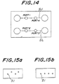
- a light beam is made incident upon the optical fibers 5 only at the positions marked by PORT1-PROT4 in Fig. 9 and also upon the reference optical fibers 5a. Then, light beams emitted from the microlens array 11 via the optical fibers 5 and light beams emitted directly from the reference optical fibers 5a are picked up by a CCD camera 41. The picked up light beams are displayed on a monitor 42 as a light spot as shown in Fig. 14. Then, centers in the light spots generated by the light beams from each sets of the reference optical fibers 5a are detected, and the thus obtained centers of each sets are connected by reference lines SU and SL on the monitor 42.
- a positional relation between the optical fiber array 1 and the spacer 21 is adjusted in such a manner that (1) the light spots PORT1 and PORT4; and PORT2 and PORT3 are positioned on the reference lines SU and SL and are not varied each other, and (2) the light spots PORT1 and PORT4 are vertically coincident with the light spots PORT2 and PORT3, respectively.
- the spacer 21 is fixed to the optical fiber array 1 by using for example adhesives of ultraviolet hardening type. It should be noted that a light beam may be made incident upon all the optical fibers 5.
- the recess portion 22 is a space.
- an optical member may be inserted into the recess portion 22.
- the optical collimator array of the invention since the optical fiber array, the spacer, and the microlens array are connected integrally to form the collimator array, it is possible to obtain the optical collimator array having a high strength and easy in manufacturing, and thus it is possible to make ease the handling of the optical collimator array.
- the spacer has a recess with window portion having a depth with respect to the face thereof connected to the optical fiber array.
- the microlens array is set in the recess window portion of the spacer in which one end portion of the microlens array is disposed to the window, and the spacer integrally connected with the microlens array is fixed to the optical fiber array, it is possible to adjust a distance between one end of the optical fiber array and one end of the microlens array at a predetermined distance i.e. a focal length precisely. As a result, it is possible to increase a converting efficiency from diverging lights to parallel lights.
- At least one set of reference optical fibers are arranged at both side portions of the optical fibers in the optical fiber array, and an axes adjustment between the optical fibers and the microlenses are performed by referring a line on the monitor generated between one reference fiber and the other reference fiber.
- the optical fiber array and the microlens array are varied in a thickness direction i.e. parallelly, the spots on the monitor are not aligned in one direction i.e. on the line, and thus it is understood that the optical fiber array and the microlens array are not arranged properly. Therefore, it is possible to perform a light axes alignment between the optical fibers and the microlenses precisely in an easy manner.
Abstract
Description
- The present invention relates to an optical collimator comprising an optical fiber array for aligning and fixing optical fibers, and a microlens array arranged near the optical fiber array at a predetermined distance and a method of aligning optical axes of the optical collimator.
- Recently, an array of Exiton Absorption Reflection Switch (EARS) having a signal regeneration function is paid attention to in, for example, TECHNICAL REPORT OF IEICE A-P92-78, SSE92-70 (1992-10) "Experiment digital free-space photonic switch". In this EARS, an optical collimator array is used at a light incident portion and a light exit portion thereof. This optical collimator array functions to supply light signals emitted through optical fibers into a two-dimensional photonic device as parallel lights.
- The optical collimator array comprises an optical fiber array for aligning and fixing optical fibers, and a microlens array arranged near the optical fiber array at a predetermined distance. In the optical collimator mentioned above, one end portion of the optical fiber array is faced to one end of the microlens array at a distance substantially equal to a focal length of the microlens array. Therefore, diverging lights emitted from the optical fiber array are converted into parallel lights.
- As to a manufacturing method of the optical collimator array mentioned above, it is assumed that the optical fiber array and the microlens array are arranged on the same substrate and are spaced at a distance substantially equal to a focal length. However, in the manufacturing method mentioned above, it is very difficult to arrange the optical fiber array and the microlens array with a distance substantially equal to a focal length and to make coincident axes of the optical fibers of the optical fiber array with axes of the microlens array. Moreover, in the construction mentioned above, a strength of the optical collimator array is lowered and a handling of the optical collimator array becomes difficult.
- That is to say, in order to align the light axes in the optical collimator array having the construction mentioned above, a light is made incident upon one end of the optical fiber array being opposite to an end facing to the microlens array, and then a light emitted from the microlens array is picked up by for example CCD camera and is displayed on a monitor. Then, spots of the lights displayed on the monitor are aligned in one direction by moving the optical fiber array and the microlens array relatively. After the spots are aligned in the manner mentioned above, the optical fiber array and the microlens array are connected by using for example adhesives of ultraviolet hardening type.
- In the method mentioned above, if a positional relation between the optical fiber array and the microlens array is varied, the spots on the monitor (4 optical fibers in the optical fiber array) are not aligned in one direction as shown in Fig. 15(a), and thus it is understood that the optical fiber array and the microlens array are not arranged properly. However, if the optical fiber array and the microlens array are varied in a thickness direction i.e. parallelly, the spots on the monitor are aligned in one direction i.e. on the line, and thus it is not understood that the optical fiber array and the microlens array are not arranged properly. Therefore, in the latter case, it is not possible to make coincident the light axes of the optical fibers in the optical fiber array with the light axes of the microlens in the microlens array, completely.
- It is an object of the invention to eliminate the drawbacks mentioned above and to provide an optical collimator array which has a high strength and can arrange an optical fiber array and a collimator array easily with a predetermined distance.
- According to the invention, an optical collimator array having an optical fiber array for aligning and fixing optical fibers, and a microlens array formed by arranging lenses integrally and connected to said optical fiber array with a predetermined distance, comprises a spacer for fixing said microlens array connected to said optical fiber array in such a manner that light axes at an end of said optical fibers in said optical fiber array are made coincident with those of said lenses in said microlens array.
- Another object of the invention is to provide a method of aligning light axes of the optical fiber array and light axes of the microlens array properly in a coincident manner.
- According to the invention, a method of aligning light axes of an optical collimator array having an optical fiber array for aligning and fixing optical fibers, and a microlens array formed by arranging lenses integrally and connected to said optical fiber array with a predetermined distance, comprises the steps of; arranging reference optical fibers at both side portions of and on the same plane of said optical fibers of said optical fiber array; emanating a light beam upon said optical fibers and said reference optical fibers; picking up light beams emitted from said microlens through said optical fibers of said optical fiber array, and light beams emitted directly from said reference optical fibers; displaying said picked up light beams as light spots on a monitor; and adjusting a positional relation between said optical fiber array and said microlens array in such a manner that light spots of said microlens array are existent on a reference line generated between light spots off said reference optical fibers.
- In the construction of the collimator array mentioned above, since the optical fiber array, the spacer, and the microlens array are connected integrally to form the collimator array, it is possible to obtain the optical collimator array having a high strength and easy in manufacturing, and thus it is possible to make ease the handling of the optical collimator array. Preferably, the spacer has a recess with window portion having a depth with respect to the face thereof connected to the optical fiber array. Therefore, if the microlens array is set in the recess window portion of the spacer in which one end portion of the microlens array is disposed to the window, and the spacer integrally connected with the microlens array is fixed to the optical fiber array, it is possible to adjust a distance between one end of the optical fiber array and one end of the microlens array at a predetermined distance i.e. a focal length precisely. As a result, it is possible to increase a converting efficiency from diverging lights to parallel lights.
- In the construction of the method of aligning light axes in the collimator array mentioned above, at least one set of reference optical fibers are arranged at both side portions of the optical fibers in the optical fiber array, and an axes adjustment between the optical fibers and the microlenses are performed by referring a line on the monitor generated between one reference fiber and the other reference fiber. In this case, even if the optical fiber array and the microlens array are varied in a thickness direction i.e. parallelly, the spots on the monitor are not aligned in one direction i.e. on the line, and thus it is understood that the optical fiber array and the microlens array are not arranged properly. Therefore, it is possible to perform a light axes alignment between the optical fibers and the microlenses precisely in an easy manner.
-
- Fig. 1 is a schematic view showing one embodiment of an optical collimator array according to the invention,
- Fig. 2 is a schematic view illustrating one embodiment of an optical fiber array according to the invention,
- Figs.3a to 3c are schematic views respectively depicting one embodiment of a spacer according to the invention,
- Fig. 4 is a schematic view showing another embodiment of the spacer according to the invention,
- Fig. 5 is a schematic view illustrating another embodiment of the optical collimator array according to the invention,
- Fig. 6 is a schematic view for explaining a method of aligning light axes between the optical fibers and the microlenses,
- Fig. 7 is a schematic view depicting a monitor image,
- Fig. 8 is a schematic view showing another embodiment of the spacer according to the invention,
- Fig. 9 is a schematic view illustrating another embodiment of the optical fiber array according to the invention,
- Fig. 10 is a schematic view depicting one embodiment of a combination of the microlens array and the spacer,
- Fig. 11 is a schematic view showing another embodiment of the microlens array,
- Fig. 12 is a schematic view illustrating another embodiment of the optical collimator array according to the invention,
- Fig. 13 is a schematic view depicting another embodiment of the optical collimator array according to the invention,
- Fig. 14 is a schematic view showing another monitor image, and
- Figs.15a and 15b are schematic views for explaining drawbacks of a conventional optical collimator array.
- Fig. 1 is a schematic view showing one embodiment of an optical collimator array according to the invention. In the embodiment shown in Fig. 1, a numeral 1 is an optical fiber array for aligning a plurality of
optical fibers 5 in one direction. In this embodiment, fouroptical fibers 5 are used. Moreover, a numeral 11 is a microlens array formed by integrally arranging a plurality of GRIN(Gradient Index)lenses 12 in one direction, the number of which is corresponding to the number of the optical fibers in the optical fiber array 1. Further, anumeral 21 is a spacer for fixing the microlens array 11. The microlens array 11 is fixed to thespacer 21 in such a manner that one end of the microlens array 11 is disposed at arecess portion 22 of thespacer 21. Then, anoptical collimator array 31 is obtained by connecting thespacer 21 to the optical fiber array 1 in such a manner that light axes at an end of theoptical fibers 5 of the optical fiber array 1 are made coincident with those ofGRIN lenses 12 of the microlens array 11 disposed at therecess portion 22. - As to the optical fiber array 1, it is preferred to use an optical fiber array disclosed in U.S. Patent Application No. 08/070619. Fig. 2 is a schematic view showing the optical fiber array 1 mentioned above. In this embodiment, the optical fiber array 1 comprises a V groove substrate 2, a
fiber fix substrate 3 and upper substrate 4, and a predetermined number of optical fibers 5 (in this case, four optical fibers 5) are fixed in the optical fiber array 1. The V groove substrate 2 comprises an upper plane 6 and alower plane 8 connected to the upper plane 6 via a step 7. In the upper plane 6,V grooves 9 for accommodating the strippedoptical fibers 5 one by one are formed, Thefiber fix substrate 3 is arranged on the upper plane 6 of the V groove substrate 2, and is used for fixing the strippedoptical fibers 5 in each center of theV grooves 9. The upper substrate 4 is arranged on thelower plane 8 of the V groove substrate 2. In a lower portion of the upper substrate 4, arecess portion 10 is formed for accommodating cover portions of theoptical fibers 5. - The microlens array 11 having a predetermined number of the
GRIN lenses 12 is formed by cutting an array ofGRIN lenses 12 arranged one dimensionally or two dimensionally, which can be obtained on the market. In this case, an arranging pitch of theGRIN lenses 12 is completely equal to an arranging pitch of theoptical fibers 5. Moreover, it is not matter that theGRIN lens 12 of the microlens array 11 are arranged in a portion not disposed to a window of therecess portion 22. - Figs. 3a to 3c are schematic views showing one embodiment of the
spacer 21. In this embodiment, thespacer 21 comprises aconnection face 23 used for a connection with the optical fiber array 1, anaccommodating portion 24 formed by a recess extended vertically to theconnection face 23 and parallelly to the optical fiber arry, and therecess portion 22 formed by another recess extended parallelly to theconnection face 23 and vertically to the optical fiber array in the opposite side of the recess for the accommodating portion. Moreover, abottom portion 24a of theaccommodating portion 24 intersects a bottom portion 22a of therecess portion 22 to form awindow portion 25 through which light beams are transmitted. - In this embodiment in which the
recess portion 22 is formed by a space only, a distance d between theconnection face 23 and thebottom portion 24a of theaccommodating portion 24 is set to a focal length of theGRIN lens 12 of the microlens array 11. This is because after theoptical collimator array 31 is assembled as shown in Fig. 1, a distance between the end of theGRIN lens 12 and the end of theoptical fiber 5 can be set to a focal length of theGRIN lens 12 completely. For example, a dimension of the optical fiber array is 5X5X2mm, and a dimension of thespacer 21 is 5X2X2mm. Moreover, a focal length of the microlens array 11 is for example 600um. - Fig. 4 is a schematic view showing the another embodiment of the
spacer 21 corresponding to the embodiment illustrated in Fig. 3c. In the embodiment shown in Fig. 4, in addition to the embodiment illustrated in Fig. 3c,grooves 26 toward theconnection face 23 are arranged in both side portions of thebottom portion 24a of theaccommodating portion 24. Therefore, the both end portions of thebottom portion 24a do not become a right angle, and the both end portions become an R shape as shown in Fig. 4. As a result, it is possible to eliminate the drawback such that the distance d can not set to a focal length completely when the microlens array 11 is set to theaccommodating portion 24, and thus it is always possible to set the distance d between the end of the microlens array 11 and theconnection face 23 to a focal length precisely. - In the optical collimator array mentioned above, if a precise working operation is performed with respect to the
spacer 21 only in such a manner that the distance between thebottom portion 24a and theconnection face 23 is set to the predetermined distance i.e. a focal length, it is easy to assemble theoptical collimator array 31 in which the distance between the optical fiber array 1 and the microlens array 11 is set to a focal length precisely. Fig. 5 is a schematic view showing another embodiment of theoptical collimator array 31 according to the invention. In the embodiment shown in Fig. 5,microlenses 13 are arranged at a portion of the microlens array 11 disposed in the window portion in stead of theGRIN lenses 12. - Fig. 6 is a schematic view for explaining a method of aligning light axes when assembling the optical collimator array according to the invention, and Fig. 7 is a schematic view illustrating a monitor image picked up by a CCD camera during the aligning operation. At first, an optical fiber array 1 for an alignment having extended portions at bath side portions of the optical fiber array 1 having a final shape is prepared. In the extended portions, V grooves 9a are formed parallelly with respect to the
V grooves 9, and referenceoptical fibers 5a are arranged in the V grooves 9a. In this manner, the optical fiber array 1 for an alignment having the referenceoptical fibers 5a arranged on the same plane of theoptical fibers 5. In the optical fiber array 1 for an alignment, the V grooves 9a are positioned outside of thespacer 21, and are positioned at a portion affected by an adhesive protrude portion A shown in Fig. 6. Then, thespacer 21 accommodating the microlens array 11 is connected to the optical fiber array 1 for an alignment thus obtained, Hereinafter, the light axis adjustment when the above connecting operation is performed will be explained. - At first, a light beam is made incident upon the
optical fibers 5 consisting the optical fiber array 1 and also upon the referenceoptical fibers 5a. Then, light beams emitted from theGRIN lenses 12 of the microlens array 11 via theoptical fibers 5 and light beams emitted directly from the referenceoptical fibers 5a are picked up by aCCD camera 41. The picked up light beams are displayed on amonitor 42 as a light spot as shown in Fig. 7. Then, centers in the light spots generated by the light beams from the referenceoptical fibers 5a are detected, and the thus obtained centers are connected by a reference line S on themonitor 42. After that, a positional relation between the optical fiber array 1 and thespacer 21 is adjusted in such a manner that all the light spots generated by the light beams from theoptical fibers 5 are positioned on the reference line S and are not varied each other. Then, thespacer 21 is fixed to the optical fiber array 1 by using for example adhesives of ultraviolet hardening type. - Fig. 8 is a schematic view showing another embodiment of the
spacer 21 preferably used for the light axis alignment according to the invention. In thespacer 21 shown in Fig. 8, a whole dimension of thespacer 21 is decreased, and adhesive relief recesses 27 is arranged in theconnection face 23. If thespacer 21 having the construction mentioned above is used, it is possible to eliminate the adhesive protrude portion A in Fig. 6, and to make small the pitch of the referenceoptical fiber 5a since thespacer 21 has a small dimension. In this case, if an image pickup region of theCCD camera 41 is small, it is possible to detect the reference light spots. - Fig. 9 is a schematic view showing another embodiment of the optical fiber array 1 according to the invention, and Fig. 10 is a schematic view illustrating one combination of the microlens array 11 and the
spacer 21. In the embodiments shown in Figs. 9 and 10, a different point from the embodiments shown in the previous figures is that a two-dimensional optical fiber array 1 is used. That is to say, theoptical fibers 5 are aligned in the horizontal direction and also aligned in the vertical direction. - In the embodiment shown in Fig. 9, four V groove substrates each having four
optical fibers 5 in the horizontal direction are stacked, and the referenceoptical fibers 5a are arranged at both side portions of the uppermost V groove substrate and the lowermost V groove substrate. The microlens array 11 and thespacer 21 used in Fig. 9 are the substantially same constructions as those of the previous embodiments, and, as shown in Fig. 10, they have dimensions extending in the vertical direction by the number of the V groove substrates to be used. Therefore, as to the microlens array 11, it is necessary to use the microlens array 11 consisting of two-dimensional microlens array as shown in Fig. 11. - Fig. 12 is a schematic view showing another embodiment of the optical collimator array according to the invention. In fig.12, the optical fiber array 1 shown in Fig. 9 and the microlens array 11 and the
spacer 12 shown in Fig. 10 are combined to form theoptical collimator array 31 having the portions arranging the referenceoptical fibers 5a. Moreover, in Fig. 13, theoptical collimator array 31, in which the portions arranging the referenceoptical fibers 5a are cut out after the light axis alignment is finished, is shown. Theoptical collimator arrays 31 shown in Figs.9 and 10 have fundamentally same constructions as those of the one-dimensionaloptical collimator arrays 31 mentioned above. - In the two-dimensional
optical collimator arrays 31 shown in Figs.9 to 13, the light axis alignment is performed fundamentally in the same manner as those of the one-dimensionaloptical collimator arrays 31 mentioned above. Also in the two-dimensionaloptical collimator arrays 31, it is sufficient to arrange at least one set of the referenceoptical fibers 5 at both side portions of at least one V groove substrate consisting of the two-dimensional optical fiber array 1. However, it is preferred to arrange two sets of the referenceoptical fibers 5 at both side portions of the uppermost V groove substrate and the lowermost V groove substrate. - At first, a light beam is made incident upon the
optical fibers 5 only at the positions marked by PORT1-PROT4 in Fig. 9 and also upon the referenceoptical fibers 5a. Then, light beams emitted from the microlens array 11 via theoptical fibers 5 and light beams emitted directly from the referenceoptical fibers 5a are picked up by aCCD camera 41. The picked up light beams are displayed on amonitor 42 as a light spot as shown in Fig. 14. Then, centers in the light spots generated by the light beams from each sets of the referenceoptical fibers 5a are detected, and the thus obtained centers of each sets are connected by reference lines SU and SL on themonitor 42. After that, a positional relation between the optical fiber array 1 and thespacer 21 is adjusted in such a manner that (1) the light spots PORT1 and PORT4; and PORT2 and PORT3 are positioned on the reference lines SU and SL and are not varied each other, and (2) the light spots PORT1 and PORT4 are vertically coincident with the light spots PORT2 and PORT3, respectively. Then, thespacer 21 is fixed to the optical fiber array 1 by using for example adhesives of ultraviolet hardening type. It should be noted that a light beam may be made incident upon all theoptical fibers 5. Moreover, since it is necessary to form the two-dimensional optical fiber array 1 precisely, it is preferred to form the optical fiber array 1 in the manner disclosed in U.S. Patent Application No. 08/036871 or in Japanese Patent Application No. hei 5-49312. - The present invention is not limited to the embodiments mentioned above, but various modifications are possible. For example, in the embodiment mentioned above, the
recess portion 22 is a space. However, if only an optical distance between the microlens array 11 and the optical fiber array 1 is always set to a predetermined distance i.e. a focal length, an optical member may be inserted into therecess portion 22. - As clearly understood from the above, according to the optical collimator array of the invention, since the optical fiber array, the spacer, and the microlens array are connected integrally to form the collimator array, it is possible to obtain the optical collimator array having a high strength and easy in manufacturing, and thus it is possible to make ease the handling of the optical collimator array. Moreover, the spacer has a recess with window portion having a depth with respect to the face thereof connected to the optical fiber array. Therefore, if the microlens array is set in the recess window portion of the spacer in which one end portion of the microlens array is disposed to the window, and the spacer integrally connected with the microlens array is fixed to the optical fiber array, it is possible to adjust a distance between one end of the optical fiber array and one end of the microlens array at a predetermined distance i.e. a focal length precisely. As a result, it is possible to increase a converting efficiency from diverging lights to parallel lights.
- Moreover, according to the method of aligning light axes in the collimator array mentioned above, at least one set of reference optical fibers are arranged at both side portions of the optical fibers in the optical fiber array, and an axes adjustment between the optical fibers and the microlenses are performed by referring a line on the monitor generated between one reference fiber and the other reference fiber. In this case, even if the optical fiber array and the microlens array are varied in a thickness direction i.e. parallelly, the spots on the monitor are not aligned in one direction i.e. on the line, and thus it is understood that the optical fiber array and the microlens array are not arranged properly. Therefore, it is possible to perform a light axes alignment between the optical fibers and the microlenses precisely in an easy manner.
Claims (9)
- An optical collimator array having an optical fiber array for aligning and fixing optical fibers, and a microlens array formed by arranging lenses integrally and connected to said optical fiber array with a predetermined distance, comprising a spacer for fixing said microlens array connected to said optical fiber array in such a manner that light axes at an end of said optical fibers in said optical fiber array are made coincident with those of said lenses in said microlens array.
- An optical collimator array according to claim 1, wherein said spacer comprises a connection face used for a connection with said optical fiber array, an accommodating portion formed by a recess extending perpendicularly to said connection face and parallelly to said optical fiber array, and a recess portion formed by another recess extended parallelly to said connection face and perpendicularly to said optical fiber array in the opposite side of the recess for the accommodating portion, in which a bottom portion of said accommodating portion intersecting a bottom portion of said recess portion to form a window portion through which light beams are transmitted.
- An optical collimator array according to claim 2, wherein said microlens array is fixed in said accommodating portion in such a manner that one end of said lenses of said microlens array is disposed at said window portion.
- An optical collimator array according to claims 1,2 or 3, wherein said optical fiber array is a two-dimensional optical fiber array in which said optical fibers are arranged two-dimensionally at an end portion thereof, and said microlens array is a two-dimensional microlens array in which said lenses are arranged two-dimensionally.
- An optical collimator array according to claim 1 or 4, wherein said optical fiber array has at least one set of reference optical fibers arranged at both side portions of and on the same plane of said optical fibers.
- An optical collimator array according to claim 2, wherein said spacer comprises grooves toward said connection face arranged in both side portions of said bottom portion of said accommodating portion.
- An optical collimator array according to claim 2, wherein said spacer comprises adhesive relief recesses arranged in said connection face.
- A method of aligning light axes of an optical collimator array having an optical fiber array for aligning and fixing optical fibers, and a microlens array formed by arranging lenses integrally and connected to said optical fiber array with a predetermined distance, comprising the steps of; arranging reference optical fibers at both side portions of and on the same plane of said optical fibers of said optical fiber array; emanating a light beam upon said optical fibers and said reference optical fibers; picking up light beams emitted from said microlens through said optical fibers of said optical fiber array, and light beams emitted directly from said reference optical fibers; displaying said picked up light beams as light spots on a monitor; and adjusting a positional relation between said optical fiber array and said microlens array in such a manner that light spots of said microlens array are existent on a reference line generated between light spots of said reference optical fibers.
- A method according to claim 8, wherein said optical fiber array is a two-dimensional optical fiber array, and at least one set of reference optical fibers are arranged.
Applications Claiming Priority (6)
| Application Number | Priority Date | Filing Date | Title |
|---|---|---|---|
| JP50866/93 | 1993-03-11 | ||
| JP5086693 | 1993-03-11 | ||
| JP5086693 | 1993-03-11 | ||
| JP18363/94 | 1994-02-15 | ||
| JP01836394A JP3333843B2 (en) | 1993-03-11 | 1994-02-15 | Optical axis alignment method of optical collimator array |
| JP1836394 | 1994-02-15 |
Publications (3)
| Publication Number | Publication Date |
|---|---|
| EP0619505A2 true EP0619505A2 (en) | 1994-10-12 |
| EP0619505A3 EP0619505A3 (en) | 1996-10-02 |
| EP0619505B1 EP0619505B1 (en) | 1999-11-03 |
Family
ID=26355042
Family Applications (1)
| Application Number | Title | Priority Date | Filing Date |
|---|---|---|---|
| EP94301696A Expired - Lifetime EP0619505B1 (en) | 1993-03-11 | 1994-03-10 | Optical collimator array and method of aligning light axes thereof |
Country Status (4)
| Country | Link |
|---|---|
| US (1) | US5446815A (en) |
| EP (1) | EP0619505B1 (en) |
| JP (1) | JP3333843B2 (en) |
| DE (1) | DE69421432T2 (en) |
Cited By (9)
| Publication number | Priority date | Publication date | Assignee | Title |
|---|---|---|---|---|
| WO2001033262A2 (en) * | 1999-11-05 | 2001-05-10 | Digital Optics Corporation | Integration of array of non-rod shaped optical with array of optical fibers |
| WO2001094995A2 (en) * | 2000-06-05 | 2001-12-13 | Calient Networks, Inc. | Fiber block construction for optical switches and techniques for making the same |
| WO2002056076A2 (en) * | 2000-10-25 | 2002-07-18 | Omm, Inc. | Fiber optic collimator array |
| US6587618B2 (en) | 2001-03-16 | 2003-07-01 | Corning Incorporated | Collimator array and method and system for aligning optical fibers to a lens array |
| US6621976B2 (en) | 1999-11-05 | 2003-09-16 | Digital Optics Corp. | Integration of array on non-rod shaped optical elements with array of fibers in a structure and associated methods |
| EP1405111A1 (en) * | 2001-07-03 | 2004-04-07 | Osaki Electric Co., Ltd. | System and method for fabricating arrayed optical fiber collimators |
| EP1462836A2 (en) * | 2001-08-10 | 2004-09-29 | 3M Innovative Properties Company | In-line shuffle modules utilizing three dimensional optical circuits |
| EP1462835A3 (en) * | 2001-08-10 | 2005-04-06 | 3M Innovative Properties Company | Optical manifold |
| EP1355125A3 (en) * | 2002-04-09 | 2007-05-23 | Ngk Insulators, Ltd. | Method for determining core positions of optical element array and an apparatus for determining core positions thereof |
Families Citing this family (62)
| Publication number | Priority date | Publication date | Assignee | Title |
|---|---|---|---|---|
| US5602951A (en) * | 1994-04-14 | 1997-02-11 | Sumitomo Electric Industries, Ltd. | Ferrule for optical connector and process for making same |
| JP3652737B2 (en) * | 1995-07-05 | 2005-05-25 | 京セラ株式会社 | Assembling method of multistage optical fiber alignment body |
| JPH09120014A (en) * | 1995-08-24 | 1997-05-06 | Ngk Insulators Ltd | Optical fiber array |
| WO1997015850A1 (en) | 1995-10-27 | 1997-05-01 | Hoya Corporation | Optical fiber fixing member and method of production thereof |
| JPH09178962A (en) * | 1995-12-27 | 1997-07-11 | Mitsubishi Gas Chem Co Inc | Optical fiber array and its production |
| EP0850886A1 (en) * | 1996-12-26 | 1998-07-01 | Hoya Corporation | Manufacturing method for glass molded products |
| US6034779A (en) * | 1997-08-08 | 2000-03-07 | Hoya Corporation | Array element examination method and array element examination device |
| US6231243B1 (en) * | 1997-08-29 | 2001-05-15 | Hoya Corporation | Preform and process for the production thereof |
| JPH11326704A (en) * | 1998-03-19 | 1999-11-26 | Ngk Insulators Ltd | Optical fiber array and its production |
| US6160937A (en) * | 1998-03-20 | 2000-12-12 | Ngk Insulators, Ltd. | Optical fiber array |
| US6048107A (en) * | 1998-05-05 | 2000-04-11 | Tektronix, Inc. | Cryogenic optical/electrical interconnect module |
| US6208787B1 (en) * | 1999-04-01 | 2001-03-27 | The Hong Kong Polytechnic University | Microlens and long period gratings |
| US6304695B1 (en) * | 1999-05-17 | 2001-10-16 | Chiaro Networks Ltd. | Modulated light source |
| US6324010B1 (en) | 1999-07-19 | 2001-11-27 | Eastman Kodak Company | Optical assembly and a method for manufacturing lens systems |
| US6243520B1 (en) | 1999-08-16 | 2001-06-05 | Schott Fiber Optics, Inc. | Optical fiber bundle having an aligned optical fiber array and method of fabricating the same |
| US6526204B1 (en) | 2000-07-11 | 2003-02-25 | Shipley Company Llc | Optical fiber array for preventing flow of glue between fibers and waveguide |
| US6737223B2 (en) | 2000-08-07 | 2004-05-18 | Shipley Company, L.L.C. | Fiber optic chip with lenslet array and method of fabrication |
| US6798968B2 (en) * | 2000-09-21 | 2004-09-28 | Shipley Company, L.L.C. | Fiber array with support post |
| US6487351B1 (en) * | 2000-11-06 | 2002-11-26 | Schott Fiber Optics | Fiber optic faceplate |
| US6839474B2 (en) * | 2000-11-16 | 2005-01-04 | Shipley Company, L.L.C. | Optical assembly for coupling with integrated optical devices and method for making |
| US6625350B2 (en) * | 2001-01-22 | 2003-09-23 | Osaki Electric Co., Ltd. | Fiber collimator array |
| JP2002277676A (en) | 2001-03-16 | 2002-09-25 | Nippon Sheet Glass Co Ltd | Optical module and its assembling method |
| US6799370B2 (en) * | 2001-06-28 | 2004-10-05 | Chiaro Networks Ltd. | Manufacturing technique for optical fiber array |
| US20030002805A1 (en) | 2001-06-29 | 2003-01-02 | John Trezza | Multi-piece fiber optic component and manufacturing technique |
| US20030002802A1 (en) * | 2001-06-29 | 2003-01-02 | John Trezza | Multi-piece fiber optic component and manufacturing technique |
| WO2003085433A1 (en) | 2001-06-29 | 2003-10-16 | Xanoptix, Inc. | Oxidized light guiding component and manufacturing technique |
| US6773166B2 (en) * | 2001-06-29 | 2004-08-10 | Xanoptix, Inc. | Multi-piece fiber optic component and manufacturing technique |
| US7831151B2 (en) | 2001-06-29 | 2010-11-09 | John Trezza | Redundant optical device array |
| US20030002804A1 (en) * | 2001-06-29 | 2003-01-02 | John Trezza | Multi-piece fiber optic component and manufacturing technique |
| US6567586B2 (en) | 2001-07-24 | 2003-05-20 | Corning Incorporated | Dual fiber collimator |
| US6597510B2 (en) | 2001-11-02 | 2003-07-22 | Corning Incorporated | Methods and apparatus for making optical devices including microlens arrays |
| US7410304B2 (en) * | 2001-11-08 | 2008-08-12 | Rohm And Haas Electronic Materials Llc | Optical fiber right angle transition |
| US6813023B2 (en) * | 2002-01-03 | 2004-11-02 | Chiaro Nerwork Ltd. | Automatic optical inter-alignment of two linear arrangements |
| US20030142923A1 (en) * | 2002-01-30 | 2003-07-31 | Chiaro Networks Ltd. | Fiberoptic array |
| US6735360B2 (en) * | 2002-01-31 | 2004-05-11 | Lightel Technologies, Inc. | Apparatus of making collimators for precise alignment of optical paths without need for adjusting positions or angles to compensate for offsets or deviations during optical device assembly |
| US6816317B2 (en) * | 2002-01-31 | 2004-11-09 | Lightel Technologies Inc. | Collimator for ready fitting to an optical device with precise optical alignment without need for adjusting positions or angles to compensate for offsets or deviations during optical device assembly and method of making same |
| KR100443984B1 (en) * | 2002-02-14 | 2004-08-11 | 삼성전자주식회사 | Apparatus and method for manufacturing collimator |
| US6913397B2 (en) * | 2002-03-04 | 2005-07-05 | Xanoptix, Inc. | Method and system for insertion of fibers of a fiber cable into a ferrule |
| JP3852349B2 (en) * | 2002-03-06 | 2006-11-29 | ヤマハ株式会社 | Microlens array coupling system, microlens array and manufacturing method thereof |
| JP2004045686A (en) * | 2002-07-11 | 2004-02-12 | Nippon Sheet Glass Co Ltd | Optical fiber array and optical fiber collimator array using the same, and optical module |
| US6886994B2 (en) * | 2002-07-18 | 2005-05-03 | Chiaro Networks Ltd. | Optical assembly and method for manufacture thereof |
| US6973242B2 (en) * | 2003-04-17 | 2005-12-06 | 3M Innovative Properties Company | Apparatus useful for guiding fiber optic ribbons into ferrules |
| US7108431B2 (en) * | 2003-04-17 | 2006-09-19 | 3M Innovative Properties Company | Ferrule for use in fiber optic connectors |
| EP1480302B1 (en) * | 2003-05-23 | 2007-07-11 | Rohm and Haas Electronic Materials, L.L.C. | External cavity semiconductor laser comprising an etalon and method for fabrication thereof |
| KR20050001620A (en) * | 2003-06-26 | 2005-01-07 | 삼성전기주식회사 | Multi channel optical switch and manufacturing method thereof |
| US20060245694A1 (en) * | 2005-04-04 | 2006-11-02 | Wenzong Chen | Multifiber MT-type connector and ferrule comprising v-groove lens array and method of manufacture |
| GB2426831B (en) * | 2005-06-01 | 2007-04-25 | Xyratex Tech Ltd | An optical connector, a communication system and a method of connecting a user circuit to an optical backplane |
| JP4761863B2 (en) * | 2005-07-15 | 2011-08-31 | モレックス インコーポレイテド | Optical connector |
| US8485735B2 (en) * | 2008-12-19 | 2013-07-16 | US Conec, Ltd | Field install fiber clip and method of use |
| US20100266245A1 (en) * | 2009-04-16 | 2010-10-21 | Hon Hai Precision Ind. Co., Ltd. | Fiber termination for fiber optic connection system |
| WO2012046464A1 (en) * | 2010-10-06 | 2012-04-12 | 古河電気工業株式会社 | Optical waveguide collimator and optical switch device |
| JP2011197633A (en) * | 2010-02-23 | 2011-10-06 | Furukawa Electric Co Ltd:The | Optical waveguide collimator and optical switch device |
| TWM449965U (en) * | 2011-06-14 | 2013-04-01 | Molex Inc | Ferrule assembly with integral latch |
| WO2013019622A2 (en) * | 2011-07-29 | 2013-02-07 | Molex Incorporated | Multi-fiber ferrule with a lens plate |
| US9323014B2 (en) | 2012-05-28 | 2016-04-26 | Mellanox Technologies Ltd. | High-speed optical module with flexible printed circuit board |
| WO2015001429A1 (en) * | 2013-07-04 | 2015-01-08 | Mellanox Technologies Ltd. | Interconnection between silicon photonics devices and optical fibers |
| WO2015035179A1 (en) * | 2013-09-06 | 2015-03-12 | Mizushima Toshirou | End cap holder |
| JP6182503B2 (en) * | 2014-05-12 | 2017-08-16 | 日本電信電話株式会社 | Optical branching device |
| CN105807366B (en) * | 2016-02-23 | 2019-04-23 | 广州宏晟光电科技股份有限公司 | A kind of large area fibre faceplate compacting tool set and production method |
| KR102076109B1 (en) * | 2019-10-08 | 2020-02-11 | 주식회사 한화 | Fiber array structure for spectral beam combining system and dual-grating spectral beam combining system using the same |
| KR102124085B1 (en) * | 2019-10-08 | 2020-06-17 | 주식회사 한화 | Fiber array structure for high power fiber laser |
| CN111323878B (en) * | 2020-04-01 | 2021-10-15 | 联合微电子中心有限责任公司 | Coupling alignment device and method for laser chip and silicon-based optoelectronic chip |
Citations (6)
| Publication number | Priority date | Publication date | Assignee | Title |
|---|---|---|---|---|
| US5037173A (en) * | 1989-11-22 | 1991-08-06 | Texas Instruments Incorporated | Optical interconnection network |
| EP0463390A2 (en) * | 1990-06-22 | 1992-01-02 | International Business Machines Corporation | Electro-optical connectors |
| US5135590A (en) * | 1991-05-24 | 1992-08-04 | At&T Bell Laboratories | Optical fiber alignment method |
| EP0506438A1 (en) * | 1991-03-29 | 1992-09-30 | Nec Corporation | Optical semiconductor array module |
| JPH04324406A (en) * | 1991-04-25 | 1992-11-13 | Fujitsu Ltd | Method for coupling optical fiber array and lens array |
| JPH05243553A (en) * | 1992-03-02 | 1993-09-21 | Nippon Telegr & Teleph Corp <Ntt> | Packaging method of surface input output type optical element |
Family Cites Families (5)
| Publication number | Priority date | Publication date | Assignee | Title |
|---|---|---|---|---|
| JPS60243609A (en) * | 1984-05-18 | 1985-12-03 | Hitachi Ltd | Optical multiplexer/demultiplexer |
| JPH0572444A (en) * | 1991-09-17 | 1993-03-26 | Fujitsu Ltd | Multifiber optical connector |
| JP3105624B2 (en) * | 1992-03-30 | 2000-11-06 | 日本碍子株式会社 | Multi-core connector and manufacturing method thereof |
| JP2557164B2 (en) * | 1992-06-03 | 1996-11-27 | 日本碍子株式会社 | Fiber array and manufacturing method thereof |
| US5257332A (en) * | 1992-09-04 | 1993-10-26 | At&T Bell Laboratories | Optical fiber expanded beam coupler |
-
1994
- 1994-02-15 JP JP01836394A patent/JP3333843B2/en not_active Expired - Fee Related
- 1994-03-10 EP EP94301696A patent/EP0619505B1/en not_active Expired - Lifetime
- 1994-03-10 US US08/208,273 patent/US5446815A/en not_active Expired - Lifetime
- 1994-03-10 DE DE69421432T patent/DE69421432T2/en not_active Expired - Fee Related
Patent Citations (6)
| Publication number | Priority date | Publication date | Assignee | Title |
|---|---|---|---|---|
| US5037173A (en) * | 1989-11-22 | 1991-08-06 | Texas Instruments Incorporated | Optical interconnection network |
| EP0463390A2 (en) * | 1990-06-22 | 1992-01-02 | International Business Machines Corporation | Electro-optical connectors |
| EP0506438A1 (en) * | 1991-03-29 | 1992-09-30 | Nec Corporation | Optical semiconductor array module |
| JPH04324406A (en) * | 1991-04-25 | 1992-11-13 | Fujitsu Ltd | Method for coupling optical fiber array and lens array |
| US5135590A (en) * | 1991-05-24 | 1992-08-04 | At&T Bell Laboratories | Optical fiber alignment method |
| JPH05243553A (en) * | 1992-03-02 | 1993-09-21 | Nippon Telegr & Teleph Corp <Ntt> | Packaging method of surface input output type optical element |
Non-Patent Citations (2)
| Title |
|---|
| PATENT ABSTRACTS OF JAPAN vol. 017, no. 161 (P-1512), 29 March 1993 & JP-A-04 324406 (FUJITSU LTD), 13 November 1992, * |
| PATENT ABSTRACTS OF JAPAN vol. 017, no. 706 (E-1483), 22 December 1993 & JP-A-05 243553 (NIPPON TELEGR & TELEPH CORP), 21 September 1993, * |
Cited By (16)
| Publication number | Priority date | Publication date | Assignee | Title |
|---|---|---|---|---|
| WO2001033262A2 (en) * | 1999-11-05 | 2001-05-10 | Digital Optics Corporation | Integration of array of non-rod shaped optical with array of optical fibers |
| WO2001033262A3 (en) * | 1999-11-05 | 2002-01-10 | Digital Optics Corp | Integration of array of non-rod shaped optical with array of optical fibers |
| US6621976B2 (en) | 1999-11-05 | 2003-09-16 | Digital Optics Corp. | Integration of array on non-rod shaped optical elements with array of fibers in a structure and associated methods |
| WO2001094995A2 (en) * | 2000-06-05 | 2001-12-13 | Calient Networks, Inc. | Fiber block construction for optical switches and techniques for making the same |
| WO2001094995A3 (en) * | 2000-06-05 | 2003-05-01 | Calient Networks Inc | Fiber block construction for optical switches and techniques for making the same |
| WO2002056076A2 (en) * | 2000-10-25 | 2002-07-18 | Omm, Inc. | Fiber optic collimator array |
| WO2002056076A3 (en) * | 2000-10-25 | 2003-08-21 | Omm Inc | Fiber optic collimator array |
| US6587618B2 (en) | 2001-03-16 | 2003-07-01 | Corning Incorporated | Collimator array and method and system for aligning optical fibers to a lens array |
| EP1405111A1 (en) * | 2001-07-03 | 2004-04-07 | Osaki Electric Co., Ltd. | System and method for fabricating arrayed optical fiber collimators |
| EP1405111A4 (en) * | 2001-07-03 | 2004-10-06 | Osaki Electric Co Ltd | System and method for fabricating arrayed optical fiber collimators |
| EP1596227A1 (en) * | 2001-07-03 | 2005-11-16 | Osaki Electric Co., Ltd. | System and method for fabricating arrayed optical fiber collimators |
| EP1462836A2 (en) * | 2001-08-10 | 2004-09-29 | 3M Innovative Properties Company | In-line shuffle modules utilizing three dimensional optical circuits |
| EP1462835A3 (en) * | 2001-08-10 | 2005-04-06 | 3M Innovative Properties Company | Optical manifold |
| EP1462836A3 (en) * | 2001-08-10 | 2005-04-06 | 3M Innovative Properties Company | In-line shuffle modules utilizing three dimensional optical circuits |
| US7597483B2 (en) | 2001-08-10 | 2009-10-06 | 3M Innovative Properties Company | Optical manifold |
| EP1355125A3 (en) * | 2002-04-09 | 2007-05-23 | Ngk Insulators, Ltd. | Method for determining core positions of optical element array and an apparatus for determining core positions thereof |
Also Published As
| Publication number | Publication date |
|---|---|
| US5446815A (en) | 1995-08-29 |
| DE69421432T2 (en) | 2000-05-04 |
| EP0619505B1 (en) | 1999-11-03 |
| JP3333843B2 (en) | 2002-10-15 |
| EP0619505A3 (en) | 1996-10-02 |
| DE69421432D1 (en) | 1999-12-09 |
| JPH075341A (en) | 1995-01-10 |
Similar Documents
| Publication | Publication Date | Title |
|---|---|---|
| US5446815A (en) | Optical collimator array including a spacer for receving a microlens and method of aligning light axes thereof | |
| US10754107B2 (en) | Coupling device having a structured reflective surface of stamped malleable metal for coupling input/output of an optical fiber | |
| KR100583646B1 (en) | Connection apparatus for parallel optical interconnect module and parallel optical interconnect module Using the same | |
| US7004645B2 (en) | VCSEL array configuration for a parallel WDM transmitter | |
| US6250820B1 (en) | Electrooptical coupling component | |
| US7794158B2 (en) | Fabrication method of optical interconnection component and optical interconnection component itself | |
| CA2738346A1 (en) | A two substrate parallel optical sub-assembly | |
| US6766076B2 (en) | Optical module and method for assembling the same | |
| CN105705974A (en) | Multi-core optical fiber | |
| EP0753776A1 (en) | Microoptical system for free-space optical interconnection and its setting method | |
| EP1413904A1 (en) | Optical module and assembling method therefor | |
| US6868207B2 (en) | Method to diffract and attenuate an optical signal | |
| US7065278B2 (en) | Optical module and method for assembling an optical module | |
| KR20180072285A (en) | apparatus for optical interconnection and coupling and method of making the same | |
| US6361222B1 (en) | Optical device and optical module provided with optical device | |
| CN115718349A (en) | High-precision double-row optical fiber array manufacturing equipment and method | |
| US6618514B1 (en) | Passive pigtail attachment apparatus and method for planar lightwave circuits | |
| US6739762B2 (en) | Optical device package | |
| JPH04288507A (en) | Optical fiber two-dimensional array module | |
| JPH05333251A (en) | Optical array module and optical array link | |
| US6989945B2 (en) | Long-throw, tight focusing optical coupler | |
| JP3519719B2 (en) | Optical collimator array | |
| JP2002182009A (en) | Collimator, collimator array, and method for manufacturing the same | |
| JP2004061664A (en) | Optical device |
Legal Events
| Date | Code | Title | Description |
|---|---|---|---|
| PUAI | Public reference made under article 153(3) epc to a published international application that has entered the european phase |
Free format text: ORIGINAL CODE: 0009012 |
|
| AK | Designated contracting states |
Kind code of ref document: A2 Designated state(s): DE FR GB |
|
| PUAL | Search report despatched |
Free format text: ORIGINAL CODE: 0009013 |
|
| RHK1 | Main classification (correction) |
Ipc: G02B 6/32 |
|
| AK | Designated contracting states |
Kind code of ref document: A3 Designated state(s): DE FR GB |
|
| 17P | Request for examination filed |
Effective date: 19970324 |
|
| 17Q | First examination report despatched |
Effective date: 19970422 |
|
| GRAG | Despatch of communication of intention to grant |
Free format text: ORIGINAL CODE: EPIDOS AGRA |
|
| GRAG | Despatch of communication of intention to grant |
Free format text: ORIGINAL CODE: EPIDOS AGRA |
|
| GRAG | Despatch of communication of intention to grant |
Free format text: ORIGINAL CODE: EPIDOS AGRA |
|
| GRAH | Despatch of communication of intention to grant a patent |
Free format text: ORIGINAL CODE: EPIDOS IGRA |
|
| GRAH | Despatch of communication of intention to grant a patent |
Free format text: ORIGINAL CODE: EPIDOS IGRA |
|
| GRAA | (expected) grant |
Free format text: ORIGINAL CODE: 0009210 |
|
| AK | Designated contracting states |
Kind code of ref document: B1 Designated state(s): DE FR GB |
|
| REF | Corresponds to: |
Ref document number: 69421432 Country of ref document: DE Date of ref document: 19991209 |
|
| ET | Fr: translation filed | ||
| PLBE | No opposition filed within time limit |
Free format text: ORIGINAL CODE: 0009261 |
|
| STAA | Information on the status of an ep patent application or granted ep patent |
Free format text: STATUS: NO OPPOSITION FILED WITHIN TIME LIMIT |
|
| 26N | No opposition filed | ||
| REG | Reference to a national code |
Ref country code: GB Ref legal event code: IF02 |
|
| PGFP | Annual fee paid to national office [announced via postgrant information from national office to epo] |
Ref country code: GB Payment date: 20040227 Year of fee payment: 11 |
|
| PGFP | Annual fee paid to national office [announced via postgrant information from national office to epo] |
Ref country code: FR Payment date: 20040319 Year of fee payment: 11 |
|
| PGFP | Annual fee paid to national office [announced via postgrant information from national office to epo] |
Ref country code: DE Payment date: 20040324 Year of fee payment: 11 |
|
| PG25 | Lapsed in a contracting state [announced via postgrant information from national office to epo] |
Ref country code: GB Free format text: LAPSE BECAUSE OF NON-PAYMENT OF DUE FEES Effective date: 20050310 |
|
| PG25 | Lapsed in a contracting state [announced via postgrant information from national office to epo] |
Ref country code: DE Free format text: LAPSE BECAUSE OF NON-PAYMENT OF DUE FEES Effective date: 20051001 |
|
| GBPC | Gb: european patent ceased through non-payment of renewal fee |
Effective date: 20050310 |
|
| PG25 | Lapsed in a contracting state [announced via postgrant information from national office to epo] |
Ref country code: FR Free format text: LAPSE BECAUSE OF NON-PAYMENT OF DUE FEES Effective date: 20051130 |
|
| REG | Reference to a national code |
Ref country code: FR Ref legal event code: ST Effective date: 20051130 |