EP0621135A1 - Ink jet apparatus - Google Patents
Ink jet apparatus Download PDFInfo
- Publication number
- EP0621135A1 EP0621135A1 EP94302909A EP94302909A EP0621135A1 EP 0621135 A1 EP0621135 A1 EP 0621135A1 EP 94302909 A EP94302909 A EP 94302909A EP 94302909 A EP94302909 A EP 94302909A EP 0621135 A1 EP0621135 A1 EP 0621135A1
- Authority
- EP
- European Patent Office
- Prior art keywords
- ink
- pressure
- nozzles
- generating means
- driving voltage
- Prior art date
- Legal status (The legal status is an assumption and is not a legal conclusion. Google has not performed a legal analysis and makes no representation as to the accuracy of the status listed.)
- Granted
Links
Images


Classifications
-
- B—PERFORMING OPERATIONS; TRANSPORTING
- B41—PRINTING; LINING MACHINES; TYPEWRITERS; STAMPS
- B41J—TYPEWRITERS; SELECTIVE PRINTING MECHANISMS, i.e. MECHANISMS PRINTING OTHERWISE THAN FROM A FORME; CORRECTION OF TYPOGRAPHICAL ERRORS
- B41J2/00—Typewriters or selective printing mechanisms characterised by the printing or marking process for which they are designed
- B41J2/005—Typewriters or selective printing mechanisms characterised by the printing or marking process for which they are designed characterised by bringing liquid or particles selectively into contact with a printing material
- B41J2/01—Ink jet
- B41J2/015—Ink jet characterised by the jet generation process
- B41J2/04—Ink jet characterised by the jet generation process generating single droplets or particles on demand
- B41J2/045—Ink jet characterised by the jet generation process generating single droplets or particles on demand by pressure, e.g. electromechanical transducers
- B41J2/04501—Control methods or devices therefor, e.g. driver circuits, control circuits
- B41J2/0458—Control methods or devices therefor, e.g. driver circuits, control circuits controlling heads based on heating elements forming bubbles
-
- B—PERFORMING OPERATIONS; TRANSPORTING
- B41—PRINTING; LINING MACHINES; TYPEWRITERS; STAMPS
- B41J—TYPEWRITERS; SELECTIVE PRINTING MECHANISMS, i.e. MECHANISMS PRINTING OTHERWISE THAN FROM A FORME; CORRECTION OF TYPOGRAPHICAL ERRORS
- B41J2/00—Typewriters or selective printing mechanisms characterised by the printing or marking process for which they are designed
- B41J2/005—Typewriters or selective printing mechanisms characterised by the printing or marking process for which they are designed characterised by bringing liquid or particles selectively into contact with a printing material
- B41J2/01—Ink jet
- B41J2/015—Ink jet characterised by the jet generation process
- B41J2/04—Ink jet characterised by the jet generation process generating single droplets or particles on demand
- B41J2/045—Ink jet characterised by the jet generation process generating single droplets or particles on demand by pressure, e.g. electromechanical transducers
- B41J2/04501—Control methods or devices therefor, e.g. driver circuits, control circuits
- B41J2/04581—Control methods or devices therefor, e.g. driver circuits, control circuits controlling heads based on piezoelectric elements
-
- B—PERFORMING OPERATIONS; TRANSPORTING
- B41—PRINTING; LINING MACHINES; TYPEWRITERS; STAMPS
- B41J—TYPEWRITERS; SELECTIVE PRINTING MECHANISMS, i.e. MECHANISMS PRINTING OTHERWISE THAN FROM A FORME; CORRECTION OF TYPOGRAPHICAL ERRORS
- B41J2/00—Typewriters or selective printing mechanisms characterised by the printing or marking process for which they are designed
- B41J2/005—Typewriters or selective printing mechanisms characterised by the printing or marking process for which they are designed characterised by bringing liquid or particles selectively into contact with a printing material
- B41J2/01—Ink jet
- B41J2/015—Ink jet characterised by the jet generation process
- B41J2/04—Ink jet characterised by the jet generation process generating single droplets or particles on demand
- B41J2/045—Ink jet characterised by the jet generation process generating single droplets or particles on demand by pressure, e.g. electromechanical transducers
- B41J2/04501—Control methods or devices therefor, e.g. driver circuits, control circuits
- B41J2/04588—Control methods or devices therefor, e.g. driver circuits, control circuits using a specific waveform
-
- B—PERFORMING OPERATIONS; TRANSPORTING
- B41—PRINTING; LINING MACHINES; TYPEWRITERS; STAMPS
- B41J—TYPEWRITERS; SELECTIVE PRINTING MECHANISMS, i.e. MECHANISMS PRINTING OTHERWISE THAN FROM A FORME; CORRECTION OF TYPOGRAPHICAL ERRORS
- B41J2/00—Typewriters or selective printing mechanisms characterised by the printing or marking process for which they are designed
- B41J2/005—Typewriters or selective printing mechanisms characterised by the printing or marking process for which they are designed characterised by bringing liquid or particles selectively into contact with a printing material
- B41J2/01—Ink jet
- B41J2/015—Ink jet characterised by the jet generation process
- B41J2/04—Ink jet characterised by the jet generation process generating single droplets or particles on demand
- B41J2/045—Ink jet characterised by the jet generation process generating single droplets or particles on demand by pressure, e.g. electromechanical transducers
- B41J2/04501—Control methods or devices therefor, e.g. driver circuits, control circuits
- B41J2/04591—Width of the driving signal being adjusted
-
- B—PERFORMING OPERATIONS; TRANSPORTING
- B41—PRINTING; LINING MACHINES; TYPEWRITERS; STAMPS
- B41J—TYPEWRITERS; SELECTIVE PRINTING MECHANISMS, i.e. MECHANISMS PRINTING OTHERWISE THAN FROM A FORME; CORRECTION OF TYPOGRAPHICAL ERRORS
- B41J2202/00—Embodiments of or processes related to ink-jet or thermal heads
- B41J2202/01—Embodiments of or processes related to ink-jet heads
- B41J2202/10—Finger type piezoelectric elements
Landscapes
- Particle Formation And Scattering Control In Inkjet Printers (AREA)
Abstract
Description
- The invention relates to an ink jet apparatus.
- As a printer head, there has conventionally been proposed a drop-on-demand type of ink jet printer head using piezoelectric ceramics. In this type of ink jet printer head, the volume of an ink chamber is changed by deforming the piezoelectric ceramics. When the volume is decreased, ink contained in the ink chamber is expelled in the form of droplets from a nozzle, whereas when the volume is increased, additional ink is introduced from an ink supply passage into the ink chamber. A plurality of such nozzles are arranged in neighboring relationship to each other, and the ink droplets are expelled from desired ones of the nozzles according to desired print data to thereby form desired characters or images on a sheet of paper or the like opposed to the nozzles.
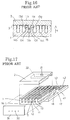
- This kind of ink jet apparatus is disclosed in U.S. Patents Nos. 4,879,568; 4,887,100; 4,992,808; and 5,003,679; U.S. Patent No. 5,028,936 (corresponding to Japanese Patent Laid-open Nos. Sho 63-247051 and 63-252750); and U.S. Patent No. 5,016,028 (corresponding to Japanese Patent Laid-open No. Hei 2-150355), for example. Figs. 15 to 19 schematically show such a conventional ink jet apparatus.
- The structure of such a conventional ink jet apparatus will now be described with reference to Fig. 15 which shows a cross section thereof.
Reference numeral 1 denotes a piezoelectric ceramics plate having a plurality ofgrooves 15 andside walls 11 partitioning thesegrooves 15 and polarized in a direction depicted by an arrow 4.Reference numeral 2 denotes a cover plate formed of a one of several materials, such as ceramics and resins. Thepiezoelectric ceramics plate 1 and thecover plate 2 are bonded together by anadhesive layer 3 formed of an epoxy adhesive, for example, whereby theplural grooves 15 are formed as a plurality ofink chambers 12 spaced from each other in a transverse direction of thepiezoelectric ceramics plate 1. Eachink chamber 12 is rectangular in cross section and is elongated over the length of thepiezoelectric ceramics plate 1. Eachside wall 11 extends over the length of theink chamber 12 it defines. Theadhesive layer 3 is formed on the upper surface of eachside wall 11. A pair ofmetal electrodes 13, for applying a driving electric field, are formed on the opposed side surfaces of eachink chamber 12 at an upper half portion thereof. All of theink chambers 12 are filled with ink. - The operation of the ink jet apparatus shown in Fig. 15 will now be described with reference to Fig. 16 showing a cross section thereof. When the
ink chamber 12b, as an exemplary one of theink chambers 12, is selected according to desired print data, a positive driving voltage is rapidly applied to themetal electrodes ink chamber 12b, and themetal electrodes ink chamber 12b are grounded. As a result, a driving electric field having adirection 14b is generated in theside wall 11b, and a driving electric field having adirection 14c is generated in theside wall 11c. As thedirections piezoelectric ceramics plate 1, theside walls ink chamber 12b by a piezoelectric thickness shear effect. This deformation of theside walls ink chamber 12b to rapidly increase the pressure of the ink contained in thegroove 12b and thereby generate a pressure wave. As a result, the ink droplets are expelled from a nozzle 32 (see Fig. 17) communicating with theink chamber 12b. Further, when the application of the driving voltage is gradually stopped, theside walls ink chamber 12b is therefore gradually decreased. As a result, additional ink is supplied from anink inlet hole 21 through a manifold 22 (see Fig. 17) into theink chamber 12b. - The above operation is merely a basic operation of the ink jet apparatus in the prior art. In an actual product, however, a driving voltage may be first applied in a such a direction as to increase the volume of the
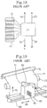
ink chamber 12b to supply the ink into theink chamber 12b before expelling the ink, and thereafter the application of the driving voltage may be rapidly stopped to return theside walls - The structure and a manufacturing method for the ink jet apparatus shown in Fig. 15 will now be described with reference to Fig. 17 showing a perspective view thereof. The
parallel grooves 15 forming theink chambers 12 are formed in thepiezoelectric ceramics plate 1 by cutting with use of a thin, disk-shaped diamond blade. All thegrooves 15 are parallel and have the same depth over almost the entire length of thepiezoelectric ceramics plate 1. The depth of eachgroove 15 is gradually reduced as it approaches arear end surface 17 of thepiezoelectric ceramics plate 1 to form ashallow groove 18 near therear end surface 17. Thereafter, themetal electrodes 13 are formed on the inner surfaces of thegrooves 15 and theshallow grooves 18 by a known technique such as sputtering. More specifically, themetal electrodes 13 are formed on the upper half portions of the inner side surfaces of thegrooves 15 and also on the inner side and bottom surfaces of theshallow grooves 18. On the other hand, theink inlet hole 21 and themanifold 22 are formed in thecover plate 2 by a method such as grinding or cutting. - Then, the lower surface of the
cover plate 2, in which themanifold 22 is formed, is bonded to the upper surface of thepiezoelectric ceramics plate 1, in which thegrooves 15 are formed, by means of an epoxy adhesive or the like, thereby defining theink chambers 12 from thegrooves 15. Then, anozzle plate 31, having thenozzles 32 arranged at the positions corresponding to the front end positions of theink chambers 12, is bonded to the front end surface of the assembly of thepiezoelectric ceramics plate 1 and thecover plate 2. Asubstrate 41, having a plurality ofconductor film patterns 42 arranged at the positions corresponding to the rear end positions of theink chambers 12, is bonded to the lower surface of thepiezoelectric ceramics plate 1, on the opposite side from thecover plate 2, by means of an epoxy adhesive or the like. Then, eachconductor film pattern 42 is connected by wire bonding through aconductor wire 43 to themetal electrode 13 which is also formed on the bottom surface of theshallow groove 18 contiguous to thecorresponding groove 15. - The structure of a control section for controlling the ink jet apparatus shown in Fig. 17 will be described with reference to Fig. 18 which shows a block diagram of the control section. The
conductor film patterns 42 formed on thesubstrate 41 are individually connected to anLSI chip 51. Also connected to theLSI chip 51 are aclock line 52, adata line 53, avoltage line 54, and aground line 55. TheLSI chip 51 determines whichnozzle 32 the ink droplets are to be expelled from according to data appearing on thedata line 53 on the basis of continuous clock pulses supplied from theclock line 52. Then, according to the result of the determination, theLSI chip 51 applies a voltage V from thevoltage line 54 to theconductor film pattern 42 connected to themetal electrode 13 in theink chamber 12 to be driven. Further, theLSI chip 51 applies the zero voltage of theground line 55 to the otherconductor film patterns 42 connected to themetal electrodes 13 in theink chambers 12 that are not to be driven. - Next, a printer employing the ink jet apparatus of the prior art will be described with reference to Fig. 19, showing a perspective view of the printer. The printer shown in Fig. 19 includes an
ink jet apparatus 61 and anozzle plate 31 similar in constitution and operation to those shown in Figs. 15 to 17. - The
ink jet apparatus 61 is fixed to acarriage 62. Anink supply tube 63 is connected to the ink inlet hole 21 (see Fig. 17). The LSI chip 51 (see Fig. 18) is installed in thecarriage 62. Aflexible cable 64 corresponds to theclock line 52, thedata line 53, thevoltage line 54, and theground line 55 shown in Fig. 18. Thecarriage 62 is reciprocated along aslider 66 in opposite directions depicted by a double-headed arrow 65, over the width of arecording paper 71. During movement of thecarriage 62, theink jet apparatus 61 operates to jet ink droplets from nozzles 32 (see Fig. 17) of thenozzle plate 31 onto therecording paper 71 supported on aplaten roller 72, thereby depositing the ink droplets on therecording paper 71. When theink jet apparatus 61 jets the ink droplets, therecording paper 71 is kept at rest. Every time thecarriage 62 changes the direction of reciprocation, therecording paper 71 is fed bypaper feed rollers 73,74 by a given amount in a direction depicted byarrow 75 in Fig. 19. Accordingly, theink jet apparatus 61 can form desired characters or images on the whole surface of therecording paper 71. - In the conventional
ink jet apparatus 61 described above, however, the pressure wave generated in the ink contained in theink chamber 12 scans toward thecorresponding nozzle 32 to jet the ink droplets from thenozzle 32. Accordingly, the number of energy generating means including theside walls 11, themetal electrodes 13, and the number of theink chambers 12 must be equal to the number of thenozzles 32. As a result, the structure of theapparatus 61 becomes complicated and a driving circuit for driving the energy generating means becomes complicated and enlarged in size. Accordingly, theink jet apparatus 61 increases in cost and size as a whole. - Further, in forming a so-called line head such that the
nozzles 32 of theink jet apparatus 61 are arranged with the same integration degree as that desired to deposit the ink droplets on therecording paper 71 and arranged over the width of therecording paper 71, the numbers of the energy generating means and theink chambers 12 are greatly increased to cause a great increase in cost and size of theink jet apparatus 61 as a whole. - It is accordingly an object of the invention to provide an ink jet apparatus which can be manufactured at a low cost with a reduced size by simplifying the structure of the apparatus and simplifying the driving circuit for driving the energy generating means to reduce the size of the driving circuit.
- According to a first aspect of the invention, there is provided an ink jet apparatus, comprising:
an ink chamber to contain ink;
a plurality of jet nozzles communicating with said ink chamber;
energy generating means for generating pressure waves in ink contained in said ink chamber to jet the ink from said jet nozzles;
energy control means for controlling said energy generating means to generate the pressure waves so that one of the pressure waves generated by said energy generating means is synthesized or compounded with another one of the pressure waves generated by said energy generating means to thereby jet the ink from said jet nozzles. - According to a second aspect of the invention, there is provided an ink ejecting device, comprising:
an elongated ink chamber open at each end;
a plurality of ink nozzles communicating with said ink chamber;
pressure generating means for generating pressure waves mounted in a first open end of said ink chamber to close the first open end;
closure means for closing the second open end; and
control means for energizing said pressure generating means to generate pressure waves in ink in said ink chamber. - With the invention, the number of energy generating means can be smaller than the number of jet nozzles, and the scanning direction of the pressure wave generated in the ink contained in the ink chamber can be substantially perpendicular to the jet nozzle. The structure of the apparatus can be simplified, and the driving circuit for driving the energy generating means can be simplified and reduced in size.
- The pressure waves generated by the energy generating means in the ink contained in the ink chamber are synthesized or compounded to thereby jet the ink from the jet nozzles.
- The invention will be more clearly understood from the following description, given by way of example only, with reference to the accompanying drawings in which:-
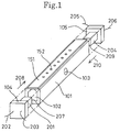
- Fig. 1 is a perspective view of an ink jet apparatus in a first preferred embodiment according to the invention;
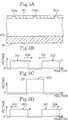
- Figs. 2A and 2B are waveform charts of driving voltage pulses to be applied to piezoelectric elements shown in Fig. 1;
- Fig. 3A is an enlarged sectional view of a part of an ink chamber shown in Fig. 1;
- Figs. 3B to 3D are waveform charts of pressure wave pulses generated by the piezoelectric elements shown in Fig. 1;
- Fig. 4 is a graph showing a relation between ink pressure and droplet velocity;
- Fig. 5 is a perspective view of an ink jet apparatus in a second preferred embodiment according to the invention;
- Fig. 6 is a perspective view of an ink jet apparatus in a third preferred embodiment according to the invention;
- Fig. 7 is a perspective view, partially broken away, of an ink jet apparatus in a fourth preferred embodiment according to the invention;
- Figs. 8A and 8B are waveform charts of driving voltage pulses to be applied to piezoelectric elements in a fifth preferred embodiment according to the present invention;
- Fig. 9A is an enlarged sectional view of a part of an ink chamber in the fifth preferred embodiment;
- Figs. 9B to 9D are waveform charts of pressure wave pulses generated by the piezoelectric elements in the fifth preferred embodiment;
- Fig. 10A is a waveform chart showing a change of ink pressure in terms of time just under a
nozzle 152d shown in Fig. 9A; - Fig. 10B is a waveform chart showing a change of ink pressure in terms of time just under a
nozzle 152e shown in Fig. 9A; - Fig. 10C is a waveform chart showing a change of ink pressure in terms of time just under a
nozzle 152c shown in Fig. 9A; - Fig. 11A is a graph showing a relation between ink pressure and droplet velocity;
- Fig. 11B is a graph showing a relation between pressure duration and droplet volume;
- Fig. 12 is a perspective view of a part of a printer employing the ink jet apparatus according to the present invention;
- Fig. 13 is a schematic diagram showing positions of deposition of ink droplets on a recording paper by the printer shown in Fig. 12;
- Fig. 14 is a view similar to Fig. 13, showing a modification in which the recording paper is fed during jetting of the ink droplets;
- Fig. 15 is a sectional view of an ink jet apparatus in the prior art;
- Fig. 16 is a sectional view showing the operation of the ink jet apparatus shown in Fig. 15;
- Fig. 17 is an exploded perspective view, partially broken away, of the ink jet apparatus shown in Fig. 15;
- Fig. 18 is a block diagram of a control section for the ink jet apparatus shown in Fig. 17; and
- Fig. 19 is a perspective view of a part of a printer employing the ink jet apparatus shown in Fig. 17.
- The structure of a first preferred embodiment according to the invention will be described with reference to Fig. 1, which is a perspective view of an ink jet apparatus of the first preferred embodiment.
-
Reference numeral 101 denotes a chamber forming member elongated in shape to define therein anink chamber 102. Theink chamber 102 extends in a longitudinal direction of thechamber forming member 101 over the length thereof. Thechamber forming member 101 is provided with anink inlet hole 103 communicating with theink chamber 102. Theink inlet hole 103 is connected through an ink supply pipe (not shown) to an ink tank (not shown). Theink chamber 102 is open at its upper portion to the upper surface of thechamber forming member 101, and anozzle plate 151 having a plurality ofnozzles 152 is bonded to the upper surface of thechamber forming member 101. Theink chamber 102 is open also at its opposite ends of thechamber forming member 101. A pair of cover members 104,105 are bonded to the opposite end surfaces of thechamber forming member 101 to close the open ends of theink chamber 102. Thus, theink chamber 102 is fully closed except theink inlet hole 103 and thenozzles 152. - An end surface of a
piezoelectric element 201 is bonded to the surface of thecover member 104 which surface is to be bonded to one of the end surfaces of thechamber forming member 101, and thepiezoelectric element 201 is disposed in theink chamber 102. A pair of conductor wires 202,203 are electrically connected to electrodes provided on thepiezoelectric element 201, so that when a driving voltage is applied between the conductor wires 202,203, thepiezoelectric element 201 produces an expansive deformation of about several nanometers to hundreds of micrometers in a direction inward of thechamber forming member 101, i.e., in a direction depicted by anarrow 208 in Fig. 1. Similarly, an end surface of anotherpiezoelectric element 204 is bonded to the surface of thecover member 105 which surface is to be bonded to the other end surface of thechamber forming member 101, and thepiezoelectric element 204 is disposed in theink chamber 102. A pair of conductor wires 205,206 are electrically connected to electrodes provided on thepiezoelectric element 204, so that when a driving voltage is applied between the conductor wires 205,206, thepiezoelectric element 204 produces an expansive deformation in a direction inward of thechamber forming member 101, i.e., in a direction depicted by anarrow 210 in Fig. 1. Each of the piezoelectric elements 201,204 may be constructed of a piezoelectric ceramic having a shape of rectangular parallelepiped in which electrodes are formed on the whole or a part of at least two opposite surfaces, or may be constructed of a stacked type of piezoelectric actuator. - The conductor wires 202,203,205,206 are electrically connected to an LSI chip constituting a voltage applying circuit, so that the application of the driving voltages to the piezoelectric elements 201,204 is controlled by the LSI chip.
- The operation of the first preferred embodiment will now be described with reference to Figs. 2A and 2B showing waveforms of driving voltage pulses to be applied to the piezoelectric elements 201,204, Figs. 3A to 3D showing a condition of synthesis of pressure wave pulses, and Fig. 4 showing a relation between ink pressure and droplet velocity.
- First, a condition of generation of pressure wave pulses by the piezoelectric elements 201,204 will be described. As shown in Fig. 2A, a plurality of driving
voltage pulses 301 each composed of arise portion 301a, ahold portion 301b, and afall portion 301c are applied between the conductor wires 202,203 (see Fig. 1). At the time of application of therise portion 301a, thepiezoelectric element 201 produces the expansive deformation in the direction of the arrow 208 (see Fig. 1) at a velocity corresponding to a rise speed of the driving voltage, so that an end surface 207 (see Fig. 1) of thepiezoelectric element 201 compresses the ink contained in theink chamber 102 in contact with theend surface 207. Thereafter at the start of the application of thehold portion 301b, the expansive deformation of thepiezoelectric element 201 is stopped, and simultaneously the compression of the ink is ended. As a result, pulses of pressure waves (compression waves) are generated from the ink near theend surface 207 to travel through the ink chamber 102 (see Fig. 1) in the direction of the arrow 208 (see Fig. 1) at a velocity of hundreds to thousands of meters per second. Thereafter, at the time of application of thefall portion 301c, thepiezoelectric element 201 produces a contractive deformation in a direction reverse to that of the expansive deformation at a velocity corresponding to a fall speed of the driving voltage, resulting in generation of a negative pressure near theend surface 207. However, as the speed of thefall portion 301c is set lower than that of therise portion 301a, the negative pressure generated near theend surface 207 is small. - Similarly, as shown in Fig. 2B, a driving
voltage pulse 303 is applied between the conductor wires 205,206 (see Fig. 1), so that a pressure wave pulse is generated from the ink near an end surface 209 (see Fig. 1) of thepiezoelectric element 204 to travel in theink chamber 102 in the direction of the arrow 210 (see Fig. 1). The drivingvoltage pulse 303 to be applied to thepiezoelectric element 204 has the same waveform as that of the drivingvoltage pulses 301 composed of therise portion 301a, thehold portion 301b, and thefall portion 301c as shown in Fig. 2A. However, a hold portion of the drivingvoltage pulse 303, corresponding to thehold portion 301b, may be omitted. Further, although the waveform of each of the drivingvoltage pulses - Next, a condition of synthesis, or compounding, of the pressure wave pulses and a condition of jetting of ink droplets will be described. It is assumed that the ink droplets are jetted from the
nozzle 152b shown in Fig. 3A. As shown in Fig. 3B, apressure wave pulse 351 having a maximum pressure P generated from thepiezoelectric element 201 moves in the direction of thearrow 208, whereas apressure wave pulse 352 having a maximum pressure P generated from thepiezoelectric element 204 moves in the direction of thearrow 210. Thus, the pressure wave pulses 351,352 approach each other. Just thereafter, as shown in Fig. 3C, the pressure wave pulses 351,352 overlap to generate asynthetic region 353 having amaximum pressure 2P obtained as the double of the maximum pressure P of each of thepressure wave pulses pressure wave pulses synthetic region 353 having themaximum pressure 2P disappears. - Thus, the scan of the pressure wave pulses 351,352 in the
ink chamber 102 causes the pressure P to be temporarily applied to thenozzles 152 as the pressure waves pass. In particular, thepressure 2P is temporarily applied to thenozzle 152b only because thesynthetic region 353 having themaximum pressure 2P is generated just under thenozzle 152b. Further, the scan of the pressure wave pulses 351,352 in theink chamber 102 also causes the pressure P to be temporarily applied to theink inlet hole 103. However, since theink inlet hole 103 is filled with the ink, the pressures of the pressure wave pulses 351,352 have almost no influence upon the ink tank, and a pressure loss of the pressure wave pulses 351,352 at theink inlet hole 103 is small. In general, an ink pressure is related to a droplet velocity as shown in Fig. 4. Accordingly, when the pressure P is set so that the ink droplets are not jetted under the pressure P, but they are jetted under thepressure 2P, the ink droplets are jetted from thenozzle 152b only by generating the pressure wave pulses 351,352. Further, by changing a timing of generation of the pressure wave pulses 351,352 from the piezoelectric elements 201,204, the ink droplets can be jetted from any one of thenozzles 152. - In jetting the ink droplets from selected ones of the
nozzles 152 so as to form desired characters or images, a train of the pluraldriving voltage pulses 301, as shown in Fig. 2A, is applied to thepiezoelectric element 201, and the singledriving voltage pulse 303 as shown in Fig. 2B is applied to thepiezoelectric element 204. In Fig. 2A, dashed lines denoteareas 302 where no driving voltage pulses are applied so as not to jet the ink droplets from unselected ones of thenozzles 152. The singularity of the drivingvoltage pulse 303 to be applied to thepiezoelectric element 204 is not limited, but a train of two or moredriving voltage pulses 303 set so as to form desired characters or images may be applied to thepiezoelectric element 204. - In the ink jet apparatus in the first preferred embodiment, the piezoelectric elements 201,204 as energy generating means, are provided at the ends of the
single ink chamber 102 communicating with theplural nozzles 152. Accordingly, the pressure waves generated in the ink contained in theink chamber 102 from the piezoelectric elements 201,204 move in a direction substantially perpendicular to thenozzles 152, and the ink droplets are jetted from thenozzles 152 by the synthesis of the pressure waves. In comparison with the conventional ink jet apparatus wherein the number of the ink chambers and the energy generating means is the same as the number of the nozzles, the ink jet apparatus in this preferred embodiment is reduced in the number of parts such that theink chamber 102 is a single chamber and the number of the piezoelectric elements 201,204 as the energy generating means, is smaller than that of thenozzles 152. Especially, in forming a so-called line head such that an ink jet apparatus is arranged with the same integration degree as that desired to deposit ink droplets on a recording paper and extends over the width of the recording paper, the conventional ink jet apparatus is required to greatly increase the numbers of the energy generating means and the ink chambers. In comparison with this, the numbers of the energy generating means and the ink chambers can be greatly reduced in the preferred embodiment. Accordingly, the structure of the ink jet apparatus can be greatly simplified, and a driving circuit for driving the energy generating means can be simplified and reduced in size. Thus, the ink jet apparatus can be manufactured at a low cost with a reduced overall size. - While the piezoelectric elements 201,204 produce the deformation in the longitudinal direction of the
ink chamber 102, the deformation may be produced in any direction other than the longitudinal direction of theink chamber 102. A second preferred embodiment embodying such a case will be described with reference to Fig. 5, in which the same parts as those of the first preferred embodiment are denoted by the same reference numerals and the explanation thereof will be omitted. - A pair of cover members 111,113 are bonded to opposite end surfaces of a
chamber forming member 101, and a pair of cover members 112,114 are bonded to the cover members 111,113, respectively. Anink chamber 102 is fully closed by thecover members 111 to 114 and anozzle plate 151 except anink inlet hole 103 and a plurality ofnozzles 152. A lower end surface of apiezoelectric element 221 is bonded to the bottom of an inner surface of thecover member 111, and a space is defined between the top of the inner surface of thecover member 111 and anupper end surface 224 of thepiezoelectric element 221. This space defined in thecover member 111 constitutes a part of theink chamber 102 and thepiezoelectric element 221 is disposed in theink chamber 102. A pair of conductor wires 222,223 are electrically connected to electrodes provided on thepiezoelectric element 221, so that when a driving voltage is applied between the conductor wires 222,223, thepiezoelectric element 221 produces an expansive deformation of about several nanometers to hundreds of micrometers in a direction depicted by anarrow 225 in Fig. 5. Similarly, a lower end surface of anotherpiezoelectric element 226 is bonded to the bottom of an inner surface of thecover member 113, and a space is defined between the top of the inner surface of thecover member 113 and anupper end surface 229 of thepiezoelectric element 226. This space defined in thecover member 113 constitutes a part of theink chamber 102 and thepiezoelectric element 226 is disposed in theink chamber 102. A pair of conductor wires 227,228 are electrically connected to electrodes provided on thepiezoelectric element 226, so that when a driving voltage is applied between the conductor wires 227,228, thepiezoelectric element 226 produces an expansive deformation in a direction depicted by anarrow 230 in Fig. 5. - The operation of the second preferred embodiment will now be described. A plurality of driving
voltage pulses 301 each composed of arise portion 301a, ahold portion 301b, and afall portion 301c as shown in Fig. 2A are applied between the conductor wires 222,223. At the time of application of therise portion 301a, thepiezoelectric element 221 produces the expansive deformation in the direction of thearrow 225 at a velocity corresponding to a rise speed of driving voltage, so that theupper end surface 224 of thepiezoelectric element 221 compresses the ink contained in the space between theupper end surface 224 and thecover member 111. Thereafter at the same time of application of thehold portion 301b, the compression of the ink is ended. As a result, pulses of pressure waves (compression waves) are generated from the ink over theupper end surface 224 to travel in theink chamber 102 in a direction depicted by anarrow 208 in Fig. 5 at a velocity of hundreds to thousands of meters per second. Similarly, a drivingvoltage pulse 303, as shown in Fig. 2B, is applied between the conductor wires 227,228, so that a pressure wave pulse is generated from the ink over theupper end surface 229 of thepiezoelectric element 226 to travel in theink chamber 102 in a direction depicted by anarrow 210 in Fig. 5. - The pressure wave pulses generated by the
piezoelectric elements 221 and the pressure wave pulse generated by thepiezoelectric element 226 are synthesized to thereby jet the ink droplets from thenozzles 152. Thus, substantially the same effect as that of the first preferred embodiment can be obtained. - While the two piezoelectric elements 201,204 or the two piezoelectric elements 221,226 are used in each of the first and second preferred embodiments, the
piezoelectric element piezoelectric element piezoelectric element nozzles 152. Thus, the ink droplets can be jetted by the use of a single piezoelectric element. Further, three or more piezoelectric elements may be used to jet the ink droplets. - While the piezoelectric elements are used as the energy generating means in the first and second preferred embodiments, any other type of energy generating means may be used. For example, an energy generating means that can be used in the invention includes a heating element capable of effecting rapid growth and disappearance of air bubbles to thereby generate pressure wave pulses in the ink contained in the
ink chamber 102, or a displacing mechanism using a solenoid, motor, oil pressure, or air pressure capable of effecting rapid displacement to thereby instantaneously compress the ink and generate pressure wave pulses. In this case, the number of the energy generating means may be two as mentioned above, or one or more than two. - Next, the structure of a third preferred embodiment according to the invention will be described with reference to Fig. 6, which is a perspective view of an ink jet apparatus of the third preferred embodiment. In this preferred embodiment, a condition of synthesis of pressure wave pulses and a condition of jetting of ink droplets are similar to those mentioned in the first preferred embodiment, and so the explanation thereof will be omitted.
-
Reference numeral 121 denotes a chamber forming member formed by spirally bending a hollow tube to define therein anink chamber 124. Theink chamber 124 spirally extends over the length of thechamber forming member 121. Thechamber forming member 121 is provided with anink inlet hole 125 communicating with theink chamber 124. Thechamber forming member 121 is further provided with a plurality ofnozzles 161 arranged in one line. - The
ink chamber 124 is open at its opposite ends and a pair ofcover members chamber forming member 121. Thus, theink chamber 124 is fully closed except theink inlet hole 125 and thenozzles 161. An end surface of apiezoelectric element 241 is bonded to the surface of thecover member 122 which is, in turn, bonded to one of the opposite end surfaces of thechamber forming member 121 and thepiezoelectric element 241 is disposed in theink chamber 124. A pair of conductor wires 242,243 are electrically connected to electrodes provided on thepiezoelectric element 241, so that when a driving voltage is applied between the conductor wires 242,243, thepiezoelectric element 241 produces an expansive deformation of about several nanometers to hundreds of micrometers in a direction depicted by anarrow 248 in Fig. 6. Similarly, an end surface of anotherpiezoelectric element 244 is bonded to the surface of thecover member 124 which is, in turn, bonded to the other end surface of thechamber forming member 121, and thepiezoelectric element 244 is disposed in theink chamber 124. A pair of conductor wires 245,246 are electrically connected to electrodes provided on thepiezoelectric element 244 so that when a driving voltage is applied between the conductor wires 245,246, thepiezoelectric element 244 produces expansive deformation in a direction depicted by anarrow 250 in Fig. 6. Each of the piezoelectric elements 241,244 can be constructed of piezoelectric ceramics having a shape of rectangular parallelepiped in which electrodes are formed on the whole or a part of at least two opposite surfaces, or can be constructed of a stacked type of piezoelectric actuator. - The operation of the third preferred embodiment will now be described. A plurality of driving
voltage pulses 301, each composed of arise portion 301a, ahold portion 301b, and afall portion 301c as shown in Fig. 2A, are applied between the conductor wires 242,243. At the time of application of therise portion 301a, thepiezoelectric element 241 produces the expansive deformation in the direction of thearrow 248 at a velocity corresponding to a rise speed of the driving voltage so that anend surface 247 of thepiezoelectric element 241 compresses the ink contained in theink chamber 124 in contact with theend surface 247. Thereafter, at the time of application of thehold portion 301b, the compression of the ink is ended. As a result, pulses of pressure waves (compression waves) are generated from the ink near theend surface 247 to travel in theink chamber 124 toward thepiezoelectric element 244 at a velocity of hundreds to thousands of meters per second. Similarly, a drivingvoltage pulse 303, as shown in Fig. 2B, is applied between the conductor wires 245,246 so that a pressure wave pulse is generated from the ink near anend surface 249 of thepiezoelectric element 244 to travel in theink chamber 124 toward thepiezoelectric element 241. - In the ink jet apparatus in the first preferred embodiment, the width of the
synthetic region 353 having themaximum pressure 2P temporarily generated is equal to the width of each of the pressure wave pulses 351,352. If the width of thesynthetic region 353 is greater than the distance between thenozzles pressure 2P of thesynthetic region 353 temporarily acts not only to thenozzle 152b but also to thenozzles nozzles pressure 2P to thenozzle 152b cannot be made so large. If this time period of application of thepressure 2P is shortened, the amount of the ink that can pass under thenozzle 152b is reduced resulting in a decrease in the volume of the ink droplets jetted from thenozzle 152b. From this point of view, the volume of the ink droplets cannot be made larger than a given value in the ink jet apparatus in the first preferred embodiment. - To the contrary, in the ink jet apparatus of the third preferred embodiment, the spiral length of the
ink chamber 124 between any two adjacent ones of thenozzles 161 is larger than the rectilinear distance between the twoadjacent nozzles 161. Accordingly, the width of the pressure wave pulse can be made considerably larger by using the piezoelectric elements 241,244 each capable of obtaining a large amount of deformation to increase the rise time of the driving voltage pulse. As a result, the volume of the ink droplets can be increased. - Further, in comparison with the conventional ink jet apparatus wherein the number of the ink chambers and the energy generating means is the same as the number of the nozzles, the ink jet apparatus in this preferred embodiment is reduced in the number of parts because there is a
single ink chamber 124 and the number of the piezoelectric elements 241,244, as the energy generating means, is smaller than the number ofnozzles 161. Accordingly, the structure of the ink jet apparatus can be greatly simplified and the driving circuit for driving the energy generating means can be simplified and reduced in size. Thus, the ink jet apparatus can be manufactured at a low cost with an overall reduced size. - While the
ink chamber 124 is spiral in the third preferred embodiment, the shape of the ink chamber may be modified to shapes other than the spiral shape. A fourth preferred embodiment embodying such a case will be described with reference to Fig. 7. -
Reference numeral 131 denotes a chamber forming member elongated in shape to define therein anink chamber 132. Theink chamber 132 substantially zigzags to extend over the length of thechamber forming member 131. Thechamber forming member 131 is provided with an ink inlet hole (not shown) communicating with theink chamber 132. Theink chamber 132 is open at its upper portion to the upper surface of thechamber forming member 131, and anozzle plate 171 having a plurality ofnozzles 172 is bonded to the upper surface of thechamber forming member 131. Theplural nozzles 172 are arranged at the same pitch as that of the zigzags of theink chamber 132. Theink chamber 132 is open also at the opposite ends of thechamber forming member 131. A pair of cover members 133,134 are bonded to the opposite end surfaces of thechamber forming member 131. Thus, theink chamber 132 is fully closed except for the ink inlet hole and thenozzles 172. - An end surface of a
piezoelectric element 251 is bonded to the surface of thecover member 133 which surface is to be bonded to one of the opposite end surfaces of thechamber forming member 131, and thepiezoelectric element 251 is disposed in theink chamber 132. A pair of conductor wires 252,253 are electrically connected to electrodes provided on thepiezoelectric element 251 so that when a driving voltage is applied between the conductor wires 252,253, thepiezoelectric element 251 produces expansive deformation of about several nanometers to hundreds of micrometers in a direction depicted by anarrow 257 in Fig. 7. Similarly, an end surface of anotherpiezoelectric element 254 is bonded to the surface of thecover member 134 which surface is to be bonded to the other end surface of thechamber forming member 131 and thepiezoelectric element 254 is disposed in theink chamber 132. A pair of conductor wires 255,256 are electrically connected to electrodes provided on thepiezoelectric element 254 so that when a driving voltage is applied between the conductor wires 255,256, thepiezoelectric element 254 produces expansive deformation in a direction depicted by anarrow 258 in Fig. 7. Each of thepiezoelectric elements - The ink jet apparatus in the fourth preferred embodiment operates similarly to the third preferred embodiment to jet the ink droplets from the
nozzles 172. Thus, substantially the same effect as that of the third preferred embodiment can be obtained. - In the ink jet apparatus in the first preferred embodiment, the possibility that the width of the
synthetic region 353 having themaximum pressure 2P shown in Fig. 3C may become the distance between thenozzles piezoelectric element 201 and the driving voltage pulse waveform to thepiezoelectric element 204. A fifth preferred embodiment embodying such an improvement in the driving voltage pulse waveforms will now be described. An ink jet apparatus in the fifth preferred embodiment has a basic structure similar to that of the ink jet apparatus in the first preferred embodiment. Accordingly, substantially the same parts as those in the first preferred embodiment are denoted by the same reference numerals and the explanation thereof will be omitted. - The operation of the fifth preferred embodiment will now be described with reference to Figs. 8A and 8B showing waveforms of driving voltage pulses to be applied to piezoelectric elements 201,204 (see Fig. 1), Figs. 9A to 9D and 10A to 10C showing a condition of synthesis of pressure wave pulses, Fig. 11A showing a relation between ink pressure and droplet velocity, and Fig. 11B showing the relationship between ink pressure duration and droplet volume.
- First, the condition for generation of pressure wave pulses to be generated by the piezoelectric elements 201,204 will be described. As shown in Fig. 8A, a driving
voltage pulse 310 formed as a repetition of triangular pulse waveforms, each composed of arise portion 310a rapidly rising and afall portion 310b gently falling is applied between a conductor wire 202 (see Fig. 1) and a conductor wire 203 (see Fig. 1) from an LSI chip. Each triangular pulse waveform is a general triangular waveform to be obtained by applying a known integrating circuit. At the time of application of therise portion 310a, thepiezoelectric element 201 produces expansive deformation in a direction depicted by anarrow 208 in Fig. 1 at a velocity corresponding to a rise speed of the driving voltage, so that an end surface 207 (see Fig. 1) of thepiezoelectric element 201 compresses the ink contained in an ink chamber 102 (see Fig. 1) near theend surface 207 to generate a positive pressure. Thereafter, starting at the application of thefall portion 310b, thepiezoelectric element 201 produces compressive deformation to generate a negative pressure near theend surface 207. Then, as shown in Fig. 9B, a pressure wave (compression wave)pulse 351 formed as a repetition of triangular pulse waveforms depending upon the drivingvoltage pulse 310 is generated from the ink near theend surface 207 to travel in theink chamber 102 in the direction of thearrow 208 at a velocity of hundreds to thousands of meters per second. - Similarly, as shown in Fig. 8B, a driving
voltage pulse 320 formed as a repetition of triangular pulse waveforms each composed of arise portion 320a gently rising and afall portion 320b rapidly falling is applied between a conductor wire 205 (see Fig. 1) and a conductor wire 206 (see Fig. 1) from the LSI chip. The drivingvoltage pulse 320 has a shape such that when it is synthesized with the drivingvoltage pulse 310, a resultant synthetic waveform has a flat top portion. Each triangular pulse waveform is also a general triangular waveform to be obtained by applying a known integrating circuit. As apparent from Figs. 8A and 8B, the inclination of therise portion 320a of thepulse 320 is reversed in sign to that of thefall portion 310b of thepulse 310. Further, the period and the number of repetitions of the triangular pulse waveforms in the drivingvoltage pulse 320 are equal to those in the drivingvoltage pulse 310. When the drivingvoltage pulse 320 is applied, a pressure wave pulse 352 (see Fig. 9B) corresponding to thepulse 320 is generated from the ink contained in theink chamber 102 near an end surface 209 (see Fig. 1) of thepiezoelectric element 204 to travel in theink chamber 102 in a direction depicted by an arrow 210 (see Fig. 1). - Next, a condition of synthesis of the pressure wave pulses and a condition of jetting of ink droplets will be described. It is assumed that the ink droplets are jetted from the
nozzle 152d shown in Fig. 9A and that the pitch of the-nozzles 152 is not equal to the width of each triangular pulse waveform of each of the pressure wave pulses 351,352. As shown in Fig. 9B, thepressure wave pulse 351 having a maximum pressure P1 and a width T generated from thepiezoelectric element 201 scans in the direction of thearrow 208, whereas thepressure wave pulse 352 having a maximum pressure Q and a width T generated from thepiezoelectric element 204 scans in the direction of thearrow 210. Thus, the pressure wave pulses 351,352 approach each other. Just thereafter, as shown in Fig. 9C, the pressure wave pulses 351,352 overlap to generate asynthetic region 353 as a synthesis of the pulses 351,352. Thereafter, when the pressure wave pulses 351,352 pass each other as shown in Fig. 9D, thesynthetic region 353 disappears. - The LSI chip applies the voltages to the
piezoelectric elements nozzle 152d shown in Fig. 9A, thereby applying to thenozzle 152d a pressure having a magnitude P1 and a duration T as shown in Fig. 10A. The magnitude P1 is obtained as a synthesis of the maximum pressure P1 of thepressure wave pulse 351 and the maximum pressure Q of thepressure wave pulse 352, and the duration T is equal to the width T of each of the pressure wave pulses 351,352. At this time, as shown in Fig. 10B, a pressure having a magnitude greater than the magnitude P1 is temporarily applied several times to thenozzle 152e adjacent to thenozzle 152d on thepiezoelectric element 204 side because thepressure wave pulse 352 passes under thenozzle 152e prior to thepressure wave pulse 351. Similarly, as shown in Fig. 10C, a pressure having a magnitude greater than the magnitude P1 is temporarily applied several times to thenozzle 152c adjacent to thenozzle 152d on thepiezoelectric element 201 side, because thepressure wave pulse 351 passes under thenozzle 152c prior to thepressure wave pulse 352. - Thus, the pressure having the magnitude P1 or the magnitude greater than the magnitude P1 is temporarily applied several times to the
nozzles 152 during scanning of thepressure wave pulses ink chamber 102. In particular, the pressure having the magnitude P1 and the duration T is applied to thenozzle 152d only. Further, the movement of the pressure wave pulses 351,352 in theink chamber 102 also causes the pressure to be temporarily applied to theink inlet hole 103. However, since theink inlet hole 103 is filled with the ink, the pressures of the pressure wave pulses 351,352 have almost no influence upon the ink tank, and the pressure loss of the pressure wave pulses 351,352 at theink inlet hole 103 is small. - In general, an ink pressure is related to a droplet velocity as shown in Fig. 11A. Accordingly, when the magnitude of the pressure is less than P0, no ink droplets are jetted. Further, a duration of application of an ink pressure is related to a droplet volume as shown in Fig. 11B. Accordingly, when the duration of the pressure is less than T0, no ink droplets are jetted. The duration T0 is a minimum duration required to jet the ink droplets under the pressure having the magnitude P0. The greater the magnitude of the ink pressure, the shorter the duration of the ink pressure.
- Thus, only when a pressure having a magnitude not less than the predetermined value P0 and a duration not less than the predetermined time T0 is applied, are the ink droplets jetted. Therefore, the ink droplets are jetted from the
nozzle 152d only to which the pressure having the magnitude P1 and the duration T meeting the above-mentioned relationship of P0 and T0 is applied, whereas the ink droplets are not jetted from thenozzles nozzles 152. - As mentioned above, in the ink jet apparatus in the fifth preferred embodiment, the driving voltage pulses 310,320 are each composed of repeated triangular pulse waveforms applied from the LSI chip to the piezoelectric elements 201,204 to thereby generate the pressure wave pulses 351,352 similar in shape to the driving voltage pulses 310,320 in the
ink chamber 102. Accordingly, the pressure wave pulses 351,352 are synthesized at a position just under the selectednozzle 152d to thereby apply to thenozzle 152d the pressure having the magnitude P1 and the duration T meeting the relationship of P0 and T0, thus jetting the ink droplets from thenozzle 152d only. While the pressure having the magnitude P1 or greater is temporarily applied to thenozzles nozzle 152d, no ink droplets are jetted from these nozzles because the pressure does not meet the relationship of P0 and T0. As a result, the ink is prevented from being deposited onto improper positions on a recording paper, thus improving the print quality. - In other words, the LSI chip as control means controls the system so that a pressure generated by synthesizing the pressure wave pulses and having a magnitude not less than a predetermined value and a duration not less than a predetermined time is applied to a subject nozzle but is not applied to other nozzles adjacent to the subject nozzle. Therefore, no ink droplets are jetted from the adjacent nozzles to thereby improve the print quality.
- In this preferred embodiment, the driving voltage pulses 310,320 each composed of repeated triangular pulse waveforms are applied to the piezoelectric elements 201,204, respectively. However, the repeated triangular pulse waveforms may be replaced by any other repeated pulse waveforms such as repeated rectangular pulse waveforms.
- Further, although the triangular pulse waveforms are repeated in the driving voltage pulses 310,320 in this preferred embodiment, the repetition of the triangular pulse waveforms is not essential.
- In this preferred embodiment, the pitch of the
nozzles 152 is not equal to the width of each triangular pulse waveform of the pressure wave pulses 351,352. However, the pitch of thenozzles 152 may be equal to the width of each triangular pulse waveform or the total width of the plural triangular pulse waveforms. In this case, the pitch is set so as not to meet the relationship of P0 and T0, because the pressure having the magnitude P1 is applied to all thenozzles 152 inclusive of thesubject nozzle 152d. - Further, although the two piezoelectric elements 201,204 are used in this preferred embodiment, three or more piezoelectric elements may be used to jet the ink droplets.
- Further, since the basic structure of this preferred embodiment is similar to that of the first preferred embodiment, the various modifications of the first preferred embodiment as mentioned above may be similarly applied to this preferred embodiment. In addition, the modifications of this preferred embodiment may be similarly applied to the first preferred embodiment.
- Next, a printer employing the ink jet apparatus according to the invention will be described with reference to Fig. 12 showing a perspective view of the printer and Fig. 13 showing the positions of deposition of ink droplets on a recording paper. The structure and operation of the ink jet apparatus employed in this printer are similar to those mentioned in the first preferred embodiment. That is, the printer shown in Fig. 12 includes an ink jet apparatus 401 and a
nozzle plate 151 similar in structure and operation to those shown in Figs. 1 to 4. - The ink jet apparatus 401 is fixed to a
carriage 402. Anink supply tube 403 is connected to an ink inlet hole 103 (see Fig. 1). Aflexible cable 404 is electrically connected to conductor wires 202,203,205,206 (see Fig. 1). Thecarriage 402 is reciprocated along aslider 406 in opposite directions as depicted by the double-headedarrow 405 in Fig. 12. During movement of thecarriage 402, the ink jet apparatus 401 operates to jet ink droplets from nozzles 152 (see Fig. 1) of thenozzle plate 151 onto arecording paper 411 supported on aplaten roller 412, thereby forming desired characters or images on therecording paper 411. When the ink jet apparatus 401 jets the ink droplets, therecording paper 411 is kept at rest. Every time thecarriage 402 changes the direction of reciprocation, therecording paper 411 is fed by paper feed rollers 473,414 by a given amount in a direction depicted by anarrow 415 in Fig. 12. Accordingly, the ink jet apparatus 401 can form desired characters or images on the whole surface of therecording paper 411. - Referring to Fig. 13, when the
carriage 402 is moved in a rightward direction of thearrow 405, the ink jet apparatus 401 jets the ink droplets from a first one of thenozzles 152 onto therecording paper 411 to deposit the ink droplets at a series ofpoints recording paper 411. Simultaneously, the ink jet apparatus 401 jets the ink droplets from a second one of thenozzles 152 adjacent to thefirst nozzle 152 on the right-hand side thereof onto therecording paper 411 to deposit the ink droplets at a series ofpoints recording paper 411. Thereafter, while thecarriage 402 changes from moving in the rightward direction to movement in a leftward direction, as shown by thearrow 405, therecording paper 411 is fed by a given amount in the direction of thearrow 415. When thecarriage 402 is moved in the leftward direction of thearrow 405, the ink jet apparatus 401 jets the ink droplets from thefirst nozzle 152 onto therecording paper 411 to deposit the ink droplets at a series ofpoints recording paper 411. Simultaneously, the ink jet apparatus 401 jets the ink droplets from thesecond nozzle 152 onto therecording paper 411 to deposit the ink droplets at a series ofpoints recording paper 411. This operation is repeated to thereby form the desired characters or images on the whole surface of therecording paper 411. - To deposit the ink droplets at regular intervals on the
recording paper 411, it is necessary to make uniform the distance between any adjacent deposition points, such as the distance between thepoints points 451e and 452d. In the printing method mentioned above, while thecarriage 402 is moved once in the rightward or leftward direction, one nozzle performs jetting of the ink droplets five times. Further, the distance between the adjacent nozzles is set to five times the distance between the adjacent deposition points, and the moving distance of thecarriage 402 in the rightward or leftward direction is set to at least four times the distance between the adjacent deposition points. However, the number of times of jetting of the ink droplets from one nozzle during the rightward or leftward movement of thecarriage 402 is not limited to five. For example, letting n denote the number of times of jetting, the distance between the adjacent nozzles becomes n times the distance between the adjacent deposition points, and the moving distance of thecarriage 402 becomes at least (n-1) times the distance between the adjacent deposition points. - The
recording paper 411 may be fed continuously at a constant speed irrespective of whether or not the ink jet apparatus 401 jets the ink droplets. The operation in this case will be described with reference to Fig. 14 showing a condition of deposition of the ink droplets. - Referring to Fig. 14, when the
carriage 402 is moved in the rightward direction of thearrow 405, the ink jet apparatus 401 jets the ink droplets from a first one of thenozzles 152 onto therecording paper 411 being fed in the direction of thearrow 415 to deposit the ink droplets at a series ofpoints recording paper 411. Simultaneously, the ink jet apparatus 401 jets the ink droplets from a second one of thenozzles 152 adjacent to thefirst nozzle 152 on the right-hand side thereof onto the recording paper being fed in the direction of the arrow 451 to deposit the ink droplets at a series ofpoints recording paper 411. Thereafter, thecarriage 402 changes the rightward direction of movement to a leftward movement direction shown by thearrow 405. When thecarriage 402 is moved in the leftward direction of thearrow 405, the ink jet apparatus 401 jets the ink droplets from thefirst nozzle 152 onto therecording paper 411 being fed in the direction of thearrow 415 to deposit the ink droplets at a series ofpoints recording paper 411. Simultaneously, the ink jet apparatus 401 jets the ink droplets from thesecond nozzle 152 onto therecording paper 411 being fed in the direction of thearrow 415 to deposit the ink droplets at a series ofpoints recording paper 411. The operation is repeated to thereby form desired characters or images on the whole surface of therecording paper 411. - In this printer, the single ink jet apparatus 401 having a single ink chamber is mounted on the
carriage 402 to deposit the ink droplets on the whole surface of therecording paper 411. In a modification, a plurality of such an ink jet apparatus may be mounted on thecarriage 402 so as to be arranged in the feeding direction of therecording paper 411, thus depositing the ink droplets on the whole surface of therecording paper 411. - In the conventional printer, the ink jet apparatus fixed to the carriage is reciprocated by a distance corresponding to the width of the recording paper. To the contrary, in the printer shown in Fig. 12, the ink jet apparatus 401 fixed to the
carriage 402 is reciprocated by a reduced distance not greater than the distance between the adjacent nozzles. Accordingly, the stroke of thecarriage 402 can be greatly reduced. In comparison with a printer having an identical number of nozzles and printing speed to the printer shown in Fig. 12, the moving speed and the acceleration acting on thecarriage 402 in changing the direction of reciprocation can be greatly reduced. Accordingly, generation of undue pressure in the ink chamber due to the acceleration acting on the ink jet apparatus 401 can be reduced to thereby reduce turbulence of jet of the ink droplets and improve the print quality. - Further, since the
carriage 402 is moved in such a manner as mentioned above, the distance between the adjacent nozzles can be actually widened. Accordingly, the width of the pressure wave can be set large to thereby enlarge the volume of the ink droplets. - Further, moving means for the carriage can be simplified in structure to thereby reduce a cost of printer.
- Although the ink jet apparatus in the first preferred embodiment is mounted in the printer shown in Fig. 12, the ink jet apparatus in any one of the second to fifth preferred embodiments mentioned above may be so mounted.
- As described above, in the ink jet apparatus according to the invention, the number of the energy generating means is smaller than the number of the jet nozzles, and the scanning direction of the pressure wave generated in the ink contained in the ink chamber is substantially perpendicular to the jet nozzles. Accordingly, the structure of the ink jet apparatus can be simplified and a driving circuit for driving the energy generating means can be simplified and reduced in size. Especially, in forming a so-called line head such that an ink jet apparatus is arranged with the same integration degree as that desired to deposit ink droplets on a recording paper and extends over the width of the recording paper, the conventional ink jet apparatus requires greatly increased numbers of energy generating means and ink chambers. In comparison with this, the numbers of the energy generating means and the ink chambers can be greatly reduced in the ink jet apparatus according to the invention. Accordingly, the ink jet apparatus can be manufactured at a low cost with a reduced size as a whole.
Claims (18)
- An ink jet apparatus, comprising:
an ink chamber to contain ink;
a plurality of jet nozzles communicating with said ink chamber;
energy generating means for generating pressure waves in ink contained in said ink chamber to jet the ink from said jet nozzles;
energy control means for controlling said energy generating means to generate the pressure waves so that one of the pressure waves generated by said energy generating means is synthesized or compounded with another one of the pressure waves generated by said energy generating means to thereby jet the ink from said jet nozzles. - An ink jet apparatus as claimed in claim 1, wherein said energy generating means are less in number than said jet nozzles.
- An ink jet apparatus as claimed in claim 2, wherein a scanning direction of said pressure waves generated in ink contained in said ink chamber by said energy generating means is substantially perpendicular to said jet nozzles.
- An ink jet apparatus as claimed in claim 1, 2 or 3, wherein said energy control means includes means for controlling said energy generating means to generate pressure waves so that the synthesized pressure wave applies a pressure having a magnitude not less than a predetermined value and a duration not less than a predetermined time to a subject one of the jet nozzles and thereby jets the ink from the subject jet nozzle.
- The ink jet apparatus as claimed in claim 4, wherein said energy control means controls said energy generating means based on a first driving voltage pulse and a second driving voltage pulse, the first driving voltage pulse being formed as a repetition of triangular pulse waveforms, each waveform composed of a rise portion rapidly rising and a fall portion gently falling, and the second driving voltage pulse being formed as a repetition of triangular pulse waveforms, each waveform composed of a rise portion gently rising and a fall portion rapidly falling.
- An ink ejecting device, comprising:
an elongated ink chamber open at each end;
a plurality of ink nozzles communicating with said ink chamber;
pressure generating means for generating pressure waves mounted in a first open end of said ink chamber to close the first open end;
closure means for closing the second open end; and
control means for energizing said pressure generating means to generate pressure waves in ink in said ink chamber. - The ink ejecting device as claimed in claim 6, wherein said closure means is a reflecting means for reflecting pressure waves generated by said pressure generating means.
- The ink ejecting device as claimed in claim 6, wherein said closure means is a second pressure generating means for generating pressure waves and is controlled by said control means.
- The ink ejecting device as claimed in claim 6, 7 or 8, wherein said plurality of ink nozzles are aligned in a straight line.
- The ink ejecting device as claimed in any one of claims 6 to 9, wherein said ink chamber is a tube that is spirally formed.
- The ink ejecting device as claimed in claim 10, wherein one ink nozzle of said plurality of ink nozzles is formed on each coil of said spirally formed tube ink chamber.
- The ink ejecting device as claimed in any one of claims 6 to 11, wherein said elongated ink chamber has formed therein a plurality of baffles to thereby create a zig-zag path for the pressure waves to follow through the ink chamber.
- The ink ejecting device as claimed in claim 12, wherein said baffles are divided into a first set of baffles extending from a base of said ink chamber toward but separated from a side of said ink chamber containing said plurality of ink nozzles and a second set of baffles extending from the side containing said plurality of ink nozzles toward but separated from said base, said first set of baffles and said second set of baffles being offset from one another to create the zig-zag path.
- The ink ejecting device as claimed in claim 13, wherein each nozzle of said plurality of nozzles is positioned between two baffles of said second set of baffles.
- The ink ejecting device as claimed in any one of claims 6 to 14, wherein a direction of movement of the pressure waves generated in the ink contained in said ink chamber by said energy generating means is substantially perpendicular to said ink nozzles.
- The ink ejecting device as claimed in any one of claims 6 to 15, wherein said control means includes means for controlling said pressure generating means to generate pressure waves so that a synthesized pressure wave applies a pressure having a magnitude not less than a predetermined value and a duration not less than a predetermined time to a subject one of the plurality of jet nozzles and thereby jets the ink from the subject jet nozzle.
- The ink ejecting device as claimed in any one of claims 6 to 16, wherein said control means controls said pressure generating means based on a first driving voltage pulse and a second driving voltage pulse, the first driving voltage pulse being formed as a repetition of a triangular pulse waveforms, each waveform composed of a rise portion rapidly rising and a fall portion gently falling, and the second driving voltage pulse being formed as a repetition of triangular pulse waveforms, each waveform composed of a rise portion gently rising and a fall portion rapidly falling.
- The ink ejecting device as claimed in claim 5 or claim 17, wherein the inclination of the rise portion of the second driving voltage pulse is reversed in sign to that of the fall portion of the first driving voltage pulse.
Applications Claiming Priority (4)
| Application Number | Priority Date | Filing Date | Title |
|---|---|---|---|
| JP97468/93 | 1993-04-23 | ||
| JP9746893A JP3144147B2 (en) | 1993-04-23 | 1993-04-23 | Ink jet device |
| JP130282/93 | 1993-06-01 | ||
| JP13028293A JPH06340068A (en) | 1993-06-01 | 1993-06-01 | Ink jet device |
Publications (2)
| Publication Number | Publication Date |
|---|---|
| EP0621135A1 true EP0621135A1 (en) | 1994-10-26 |
| EP0621135B1 EP0621135B1 (en) | 1997-06-18 |
Family
ID=26438632
Family Applications (1)
| Application Number | Title | Priority Date | Filing Date |
|---|---|---|---|
| EP94302909A Expired - Lifetime EP0621135B1 (en) | 1993-04-23 | 1994-04-22 | Ink jet apparatus |
Country Status (3)
| Country | Link |
|---|---|
| US (1) | US5587727A (en) |
| EP (1) | EP0621135B1 (en) |
| DE (1) | DE69403849T2 (en) |
Cited By (4)
| Publication number | Priority date | Publication date | Assignee | Title |
|---|---|---|---|---|
| WO1996031351A1 (en) * | 1995-04-04 | 1996-10-10 | Videojet Systems International, Inc. | A droplet generator for a continuous stream ink jet print head |
| EP1319511A1 (en) * | 2001-12-11 | 2003-06-18 | Seiko Epson Corporation | Liquid jetting apparatus and method for driving the same |
| US6779866B2 (en) | 2001-12-11 | 2004-08-24 | Seiko Epson Corporation | Liquid jetting apparatus and method for driving the same |
| GB2482873A (en) * | 2010-08-17 | 2012-02-22 | The Technology Partnership Plc | Droplet generator for dispensing multiple streams of uniform liquid droplets |
Families Citing this family (2)
| Publication number | Priority date | Publication date | Assignee | Title |
|---|---|---|---|---|
| JPH10296971A (en) * | 1997-04-23 | 1998-11-10 | Minolta Co Ltd | Ink jet recorder |
| AUPP654098A0 (en) * | 1998-10-16 | 1998-11-05 | Silverbrook Research Pty Ltd | Micromechanical fluid supply system (fluid05) |
Citations (6)
| Publication number | Priority date | Publication date | Assignee | Title |
|---|---|---|---|---|
| US4291316A (en) * | 1975-06-03 | 1981-09-22 | Ricoh Co., Ltd. | System for driving ink drop generator of ink-jet printer |
| EP0094032A1 (en) * | 1982-05-07 | 1983-11-16 | Siemens Aktiengesellschaft | Device for the ejection of ink droplets |
| EP0275211A2 (en) * | 1987-01-16 | 1988-07-20 | Xerox Corporation | Travelling wave droplet generator for an ink jet printer |
| EP0354706A2 (en) * | 1988-08-10 | 1990-02-14 | Hewlett-Packard Company | Ink flow control system and method for an ink jet printer |
| EP0550148A2 (en) * | 1991-12-30 | 1993-07-07 | Xerox Corporation | Acoustic ink printhead with apertured member and flowing ink |
| US5229793A (en) * | 1990-12-26 | 1993-07-20 | Xerox Corporation | Liquid surface control with an applied pressure signal in acoustic ink printing |
Family Cites Families (7)
| Publication number | Priority date | Publication date | Assignee | Title |
|---|---|---|---|---|
| US4303927A (en) * | 1977-03-23 | 1981-12-01 | International Business Machines Corporation | Apparatus for exciting an array of ink jet nozzles and method of forming |
| JPS60104337A (en) * | 1983-11-11 | 1985-06-08 | Fujitsu Ltd | Ink jet head |
| US4887100A (en) * | 1987-01-10 | 1989-12-12 | Am International, Inc. | Droplet deposition apparatus |
| US4992808A (en) * | 1987-01-10 | 1991-02-12 | Xaar Limited | Multi-channel array, pulsed droplet deposition apparatus |
| US5003679A (en) * | 1987-01-10 | 1991-04-02 | Xaar Limited | Method of manufacturing a droplet deposition apparatus |
| GB8824014D0 (en) * | 1988-10-13 | 1988-11-23 | Am Int | High density multi-channel array electrically pulsed droplet deposition apparatus |
| US5461403A (en) * | 1991-08-16 | 1995-10-24 | Compaq Computer Corporation | Droplet volume modulation techniques for ink jet printheads |
-
1994
- 1994-04-04 US US08/222,594 patent/US5587727A/en not_active Expired - Lifetime
- 1994-04-22 DE DE69403849T patent/DE69403849T2/en not_active Expired - Lifetime
- 1994-04-22 EP EP94302909A patent/EP0621135B1/en not_active Expired - Lifetime
Patent Citations (6)
| Publication number | Priority date | Publication date | Assignee | Title |
|---|---|---|---|---|
| US4291316A (en) * | 1975-06-03 | 1981-09-22 | Ricoh Co., Ltd. | System for driving ink drop generator of ink-jet printer |
| EP0094032A1 (en) * | 1982-05-07 | 1983-11-16 | Siemens Aktiengesellschaft | Device for the ejection of ink droplets |
| EP0275211A2 (en) * | 1987-01-16 | 1988-07-20 | Xerox Corporation | Travelling wave droplet generator for an ink jet printer |
| EP0354706A2 (en) * | 1988-08-10 | 1990-02-14 | Hewlett-Packard Company | Ink flow control system and method for an ink jet printer |
| US5229793A (en) * | 1990-12-26 | 1993-07-20 | Xerox Corporation | Liquid surface control with an applied pressure signal in acoustic ink printing |
| EP0550148A2 (en) * | 1991-12-30 | 1993-07-07 | Xerox Corporation | Acoustic ink printhead with apertured member and flowing ink |
Cited By (5)
| Publication number | Priority date | Publication date | Assignee | Title |
|---|---|---|---|---|
| WO1996031351A1 (en) * | 1995-04-04 | 1996-10-10 | Videojet Systems International, Inc. | A droplet generator for a continuous stream ink jet print head |
| US6152556A (en) * | 1995-04-04 | 2000-11-28 | Marconi Data Systems Inc. | Droplet generator for a continuous stream ink jet print head |
| EP1319511A1 (en) * | 2001-12-11 | 2003-06-18 | Seiko Epson Corporation | Liquid jetting apparatus and method for driving the same |
| US6779866B2 (en) | 2001-12-11 | 2004-08-24 | Seiko Epson Corporation | Liquid jetting apparatus and method for driving the same |
| GB2482873A (en) * | 2010-08-17 | 2012-02-22 | The Technology Partnership Plc | Droplet generator for dispensing multiple streams of uniform liquid droplets |
Also Published As
| Publication number | Publication date |
|---|---|
| DE69403849T2 (en) | 1997-11-06 |
| EP0621135B1 (en) | 1997-06-18 |
| DE69403849D1 (en) | 1997-07-24 |
| US5587727A (en) | 1996-12-24 |
Similar Documents
| Publication | Publication Date | Title |
|---|---|---|
| RU2184038C2 (en) | Process of operation of device for precipitation of drops versions) and device for precipitation of drops | |
| US5461403A (en) | Droplet volume modulation techniques for ink jet printheads | |
| JP2881566B2 (en) | Multiple tone printing method | |
| US3946398A (en) | Method and apparatus for recording with writing fluids and drop projection means therefor | |
| US5909230A (en) | Recording apparatus using motional inertia of marking fluid | |
| US6705696B1 (en) | Method of driving inkjet recording head and inkjet recording apparatus | |
| WO1996010488A1 (en) | Method of multi-tone printing | |
| IL102824A (en) | Sidewall actuator for a high density ink jet printhead | |
| US6402280B2 (en) | Printhead with close-packed configuration of alternating sized drop ejectors and method of firing such drop ejectors | |
| US20130241985A1 (en) | Ink-jet recording apparatus | |
| US5587727A (en) | Ink jet apparatus using pressure wave intersection to eject ink droplets | |
| CA2238424C (en) | Operation of pulsed droplet deposition apparatus | |
| JPH09277509A (en) | Ink-jet recording apparatus | |
| JP3144147B2 (en) | Ink jet device | |
| JP7122051B1 (en) | How to drive the print head | |
| EP0461938A2 (en) | Ink jet recording method and ink jet recording apparatus using same | |
| JP3116661B2 (en) | Ink jet device | |
| US6511157B1 (en) | Ink jet printerhead with a plurality of nozzles and two distinct groups of filters | |
| JP3311085B2 (en) | Ink ejection device | |
| JPH06305139A (en) | Ink jet device | |
| GB2616646A (en) | Methods and apparatus for droplet deposition | |
| CA2249221C (en) | Operation of droplet deposition apparatus | |
| WO1997009175A2 (en) | Ink jet recording device | |
| JPH06340068A (en) | Ink jet device | |
| JPH0331141B2 (en) |
Legal Events
| Date | Code | Title | Description |
|---|---|---|---|
| PUAI | Public reference made under article 153(3) epc to a published international application that has entered the european phase |
Free format text: ORIGINAL CODE: 0009012 |
|
| AK | Designated contracting states |
Kind code of ref document: A1 Designated state(s): DE GB SE |
|
| 17P | Request for examination filed |
Effective date: 19950119 |
|
| 17Q | First examination report despatched |
Effective date: 19960112 |
|
| GRAG | Despatch of communication of intention to grant |
Free format text: ORIGINAL CODE: EPIDOS AGRA |
|
| GRAH | Despatch of communication of intention to grant a patent |
Free format text: ORIGINAL CODE: EPIDOS IGRA |
|
| GRAH | Despatch of communication of intention to grant a patent |
Free format text: ORIGINAL CODE: EPIDOS IGRA |
|
| GRAA | (expected) grant |
Free format text: ORIGINAL CODE: 0009210 |
|
| AK | Designated contracting states |
Kind code of ref document: B1 Designated state(s): DE GB SE |
|
| REF | Corresponds to: |
Ref document number: 69403849 Country of ref document: DE Date of ref document: 19970724 |
|
| PGFP | Annual fee paid to national office [announced via postgrant information from national office to epo] |
Ref country code: SE Payment date: 19980416 Year of fee payment: 5 |
|
| PLBE | No opposition filed within time limit |
Free format text: ORIGINAL CODE: 0009261 |
|
| STAA | Information on the status of an ep patent application or granted ep patent |
Free format text: STATUS: NO OPPOSITION FILED WITHIN TIME LIMIT |
|
| 26N | No opposition filed | ||
| PG25 | Lapsed in a contracting state [announced via postgrant information from national office to epo] |
Ref country code: SE Free format text: LAPSE BECAUSE OF NON-PAYMENT OF DUE FEES Effective date: 19990423 |
|
| EUG | Se: european patent has lapsed |
Ref document number: 94302909.0 |
|
| REG | Reference to a national code |
Ref country code: GB Ref legal event code: IF02 |
|
| PGFP | Annual fee paid to national office [announced via postgrant information from national office to epo] |
Ref country code: GB Payment date: 20130326 Year of fee payment: 20 |
|
| PGFP | Annual fee paid to national office [announced via postgrant information from national office to epo] |
Ref country code: DE Payment date: 20130430 Year of fee payment: 20 |
|
| REG | Reference to a national code |
Ref country code: DE Ref legal event code: R071 Ref document number: 69403849 Country of ref document: DE |
|
| REG | Reference to a national code |
Ref country code: GB Ref legal event code: PE20 Expiry date: 20140421 |
|
| PG25 | Lapsed in a contracting state [announced via postgrant information from national office to epo] |
Ref country code: GB Free format text: LAPSE BECAUSE OF EXPIRATION OF PROTECTION Effective date: 20140421 |
|
| PG25 | Lapsed in a contracting state [announced via postgrant information from national office to epo] |
Ref country code: DE Free format text: LAPSE BECAUSE OF EXPIRATION OF PROTECTION Effective date: 20140423 |