EP0621432A1 - Sealed connection device for a hose and a rigid pipe end - Google Patents
Sealed connection device for a hose and a rigid pipe end Download PDFInfo
- Publication number
- EP0621432A1 EP0621432A1 EP94400843A EP94400843A EP0621432A1 EP 0621432 A1 EP0621432 A1 EP 0621432A1 EP 94400843 A EP94400843 A EP 94400843A EP 94400843 A EP94400843 A EP 94400843A EP 0621432 A1 EP0621432 A1 EP 0621432A1
- Authority
- EP
- European Patent Office
- Prior art keywords
- ring
- outer ring
- flexible conduit
- rigid
- end piece
- Prior art date
- Legal status (The legal status is an assumption and is not a legal conclusion. Google has not performed a legal analysis and makes no representation as to the accuracy of the status listed.)
- Granted
Links
Images


Classifications
-
- B—PERFORMING OPERATIONS; TRANSPORTING
- B21—MECHANICAL METAL-WORKING WITHOUT ESSENTIALLY REMOVING MATERIAL; PUNCHING METAL
- B21D—WORKING OR PROCESSING OF SHEET METAL OR METAL TUBES, RODS OR PROFILES WITHOUT ESSENTIALLY REMOVING MATERIAL; PUNCHING METAL
- B21D39/00—Application of procedures in order to connect objects or parts, e.g. coating with sheet metal otherwise than by plating; Tube expanders
- B21D39/04—Application of procedures in order to connect objects or parts, e.g. coating with sheet metal otherwise than by plating; Tube expanders of tubes with tubes; of tubes with rods
-
- F—MECHANICAL ENGINEERING; LIGHTING; HEATING; WEAPONS; BLASTING
- F16—ENGINEERING ELEMENTS AND UNITS; GENERAL MEASURES FOR PRODUCING AND MAINTAINING EFFECTIVE FUNCTIONING OF MACHINES OR INSTALLATIONS; THERMAL INSULATION IN GENERAL
- F16L—PIPES; JOINTS OR FITTINGS FOR PIPES; SUPPORTS FOR PIPES, CABLES OR PROTECTIVE TUBING; MEANS FOR THERMAL INSULATION IN GENERAL
- F16L33/00—Arrangements for connecting hoses to rigid members; Rigid hose connectors, i.e. single members engaging both hoses
- F16L33/20—Undivided rings, sleeves or like members contracted on the hose or expanded in the hose by means of tools; Arrangements using such members
- F16L33/207—Undivided rings, sleeves or like members contracted on the hose or expanded in the hose by means of tools; Arrangements using such members only a sleeve being contracted on the hose
- F16L33/2071—Undivided rings, sleeves or like members contracted on the hose or expanded in the hose by means of tools; Arrangements using such members only a sleeve being contracted on the hose the sleeve being a separate connecting member
-
- F—MECHANICAL ENGINEERING; LIGHTING; HEATING; WEAPONS; BLASTING
- F16—ENGINEERING ELEMENTS AND UNITS; GENERAL MEASURES FOR PRODUCING AND MAINTAINING EFFECTIVE FUNCTIONING OF MACHINES OR INSTALLATIONS; THERMAL INSULATION IN GENERAL
- F16L—PIPES; JOINTS OR FITTINGS FOR PIPES; SUPPORTS FOR PIPES, CABLES OR PROTECTIVE TUBING; MEANS FOR THERMAL INSULATION IN GENERAL
- F16L37/00—Couplings of the quick-acting type
- F16L37/08—Couplings of the quick-acting type in which the connection between abutting or axially overlapping ends is maintained by locking members
- F16L37/084—Couplings of the quick-acting type in which the connection between abutting or axially overlapping ends is maintained by locking members combined with automatic locking
- F16L37/088—Couplings of the quick-acting type in which the connection between abutting or axially overlapping ends is maintained by locking members combined with automatic locking by means of a split elastic ring
- F16L37/0885—Couplings of the quick-acting type in which the connection between abutting or axially overlapping ends is maintained by locking members combined with automatic locking by means of a split elastic ring with access to the split elastic ring from a radial or tangential opening in the coupling
Abstract
Description
L'invention concerne un dispositif de jonction étanche entre un conduit souple et un embout tubulaire rigide, notamment pour un circuit de refroidissement d'un véhicule automobile, et une installation de montage de ce dispositif.The invention relates to a sealed junction device between a flexible duct and a rigid tubular end piece, in particular for a cooling circuit of a motor vehicle, and an installation for mounting this device.
Les véhicules automobiles modernes comportent un capot de plus en plus effilé, en vue de l'amélioration du coefficient de pénétration du véhicule dans l'air.Modern motor vehicles have an increasingly tapered hood, with a view to improving the coefficient of penetration of the vehicle into the air.
La place disponible sous le capot pour le radiateur est donc réduite par rapport aux véhicules plus anciens.The space available under the hood for the radiator is therefore reduced compared to older vehicles.
En conséquence, l'eau du circuit de refroidissement est donc relativement moins refroidie sur les véhicules modernes et cette eau se trouve, pendant la marche du véhicule, à une pression et à une température sensiblement supérieures à la pression et à la température de l'eau dans les circuits de refroidissement des véhicules plus anciens.Consequently, the water in the cooling circuit is therefore relatively less cooled on modern vehicles and this water is, during the running of the vehicle, at a pressure and at a temperature substantially higher than the pressure and the temperature of the water in the cooling systems of older vehicles.
Cette augmentation de pression entraîne des risques de fuite au niveau des jonctions entre les conduits de raccordement souples et les embouts de raccordement rigides, par exemple dans le cas des conduits de jonction entre le radiateur et le moteur.This increase in pressure leads to risks of leakage at the junctions between the flexible connection conduits and the rigid connection nozzles, for example in the case of the connection conduits between the radiator and the engine.
Dans l'état de la technique, les conduits de raccordement souples sont engagés sur l'embout rigide correspondant et fixés de manière étanche sur cet embout grâce à un collier de serrage disposé autour du raccord souple.In the prior art, the flexible connection conduits are engaged on the corresponding rigid end piece and fixed in leaktight manner on this end piece by means of a clamping collar disposed around the flexible connection.
Les colliers de serrage utilisés peuvent être de différents types.The cable ties used can be of different types.
On utilise par exemple des colliers élastiques, mais ces colliers n'assurent pas une très bonne étanchéité lorsque la pression dans le circuit de refroidissement est sensiblement supérieure à la pression atmosphérique.For example, elastic collars are used, but these collars do not provide a very good seal when the pressure in the cooling circuit is substantially higher than atmospheric pressure.
De plus, ces colliers élastiques nécessitent l'utilisation d'outils spécifiques pour leur montage et leur démontage.In addition, these elastic collars require the use of specific tools for their assembly and disassembly.
On peut également utiliser des colliers de serrage à crémaillère mais ces colliers requièrent également l'utilisation d'un outillage spécifique pour leur montage et leur démontage.Rack clamps can also be used, but these clamps also require the use of specific tools for their assembly and disassembly.
De plus, le démontage de tels colliers est une opération très difficile.In addition, dismantling such collars is a very difficult operation.
Il est également possible d'utiliser des colliers à vis à direction tangentielle mais ces colliers sont très difficiles à placer sur l'extrémité de raccordement du conduit et l'embout. De plus, le bon serrage de ces colliers ne peut être contrôlé visuellement.It is also possible to use screw collars with tangential direction but these collars are very difficult to place on the connection end of the conduit and the end piece. In addition, the correct tightening of these collars cannot be checked visually.
En conséquence, les dispositifs de jonction des circuits de refroidissement dans lesquels un conduit souple est enfilé sur un embout rigide du circuit et serré par un collier ne donnent pas satisfaction dans les conditions actuelles et a fortiori, dans le cas de circuits de refroidissement fonctionnant sous haute pression.Consequently, the devices for joining the cooling circuits in which a flexible duct is threaded onto a rigid end piece of the circuit and tightened by a collar are not satisfactory under current conditions and a fortiori in the case of cooling circuits operating under high pressure.
De plus, ces dispositifs ne peuvent pas être montés de façon automatique.In addition, these devices cannot be mounted automatically.
Dans les demandes de brevet français n° 88-03458 et 90-12569 aux noms des Demanderesses, on a proposé des dispositifs de jonction entre un conduit souple et un embout tubulaire rigide, notamment pour un circuit de refroidissement d'un véhicule automobile, dans lequel le conduit souple est fixé de manière étanche à l'embout rigide par des organes de maintien et d'étanchéité comportant deux éléments tubulaires rigides disposés de manière coaxiale par rapport à l'extrémité de jonction du conduit souple, à l'intérieur et à l'extérieur de ce conduit, respectivement, de manière que le conduit soit maintenu par serrage ou par sertissage entre les deux éléments tubulaires. La fixation et l'étanchéité du conduit souple par rapport à l'embout rigide sont assurées par coopération de l'un au moins des éléments tubulaires interne et externe avec un moyen de maintien approprié et avec un joint d'étanchéité torique.In French patent applications Nos. 88-03458 and 90-12569 in the names of the Applicants, junction devices have been proposed between a flexible conduit and a rigid tubular end piece, in particular for a cooling circuit of a motor vehicle, in which the flexible conduit is fixed in a leaktight manner to the rigid end piece by holding and sealing members comprising two rigid tubular elements disposed coaxially with respect to the junction end of the flexible conduit, inside and at the outside of this conduit, respectively, so that the conduit is held by clamping or crimping between the two tubular elements. Fixing and sealing the flexible conduit relative to the rigid endpiece are ensured by cooperation of at least one of the internal and external tubular elements with an appropriate holding means and with an O-ring seal.
Dans le FR-A-88-03458, le moyen de maintien est constitué par un cavalier ou une bague élastique comportant des branches pouvant s'écarter de manière élastique, introduites dans des fentes traversant la paroi de l'embout tubulaire sur une partie de sa périphérie et dans une gorge prévue sur l'un des éléments tubulaires rigides, les fentes et la gorge étant mises en coïncidence pour réaliser la jonction.In FR-A-88-03458, the holding means consists of a jumper or an elastic ring comprising branches which can move apart in an elastic manner, introduced into slots passing through the wall of the tubular end piece on a part of its periphery and in a groove provided on one of the rigid tubular elements, the slots and the groove being brought into coincidence to achieve the junction.
Dans le FR-A-90-12569, le cavalier peut être monté préalablement sur l'embout rigide, de manière que ses branches introduites dans les fentes de l'embout et en saillie à l'intérieur de l'alésage de l'embout puissent être écartées par des crans en saillie sur l'un des éléments tubulaires, lors de l'engagement en force, dans la direction axiale, des éléments tubulaires solidaires du conduit souple, à l'intérieur de l'embout rigide. Les branches du cavalier se referment ensuite de manière élastique pour assurer le maintien axial du conduit souple à l'intérieur de l'embout, par coopération avec les crans en saillie.In FR-A-90-12569, the jumper can be mounted beforehand on the rigid end piece, so that its branches inserted into the slots of the end piece and projecting inside the bore of the end piece can be separated by notches projecting from one of the tubular elements, during the force engagement, in the axial direction, of the tubular elements integral with the flexible conduit, inside the rigid end piece. The branches of the rider then close resiliently to ensure the axial retention of the flexible conduit inside the end piece, by cooperation with the projecting notches.
Un tel dispositif est utilisable dans le cas où l'embout rigide est un embout femelle dont l'alésage est prévu pour recevoir le conduit souple équipé des éléments tubulaires constituant la partie mâle de la jonction.Such a device can be used in the case where the rigid end piece is a female end piece whose bore is designed to receive the flexible conduit fitted with tubular elements constituting the male part of the junction.
Ce type de jonction n'est pas applicable, dans le cas d'un embout tubulaire rigide de petit diamètre destiné à être engagé à l'intérieur du conduit souple.This type of junction is not applicable, in the case of a rigid tubular end piece of small diameter intended to be engaged inside the flexible conduit.
En outre, l'agrafe ou cavalier doit être montée sur l'embout rigide qui est solidaire du radiateur ou du moteur du véhicule. Ce montage à l'intérieur du compartiment moteur du véhicule peut présenter certaines difficultés.In addition, the clip or jumper must be mounted on the rigid endpiece which is integral with the radiator or the vehicle engine. This mounting inside the engine compartment of the vehicle can present certain difficulties.
De même, il peut être difficile de réaliser le démontage de l'agrafe ou cavalier pour libérer la jonction.Similarly, it may be difficult to disassemble the clip or jumper to release the junction.
Le but de l'invention est donc de proposer un dispositif de jonction étanche entre un conduit souple et un embout tubulaire rigide, notamment pour un circuit de refroidissement d'un véhicule automobile, comportant deux éléments tubulaires rigides disposés de manière coaxiale, respectivement à l'extérieur et à l'intérieur d'une extrémité de raccordement de ce conduit et désignés respectivement comme bague externe et bague interne, un joint d'étanchéité torique intercalé entre l'un des éléments tubulaires et l'embout rigide et des moyens de maintien de l'un au moins des éléments tubulaires par rapport à l'embout rigide, ce dispositif de jonction pouvant être utilisé dans le cas où l'embout tubulaire rigide est la partie mâle de la jonction et permettant de faciliter la mise en place et le démontage des moyens de maintien.The object of the invention is therefore to propose a sealed junction device between a flexible duct and a rigid tubular end piece, in particular for a cooling circuit of a motor vehicle, comprising two rigid tubular elements arranged coaxially, respectively at l outside and inside a connection end of this duct and designated respectively as outer ring and inner ring, an O-ring inserted between one of the tubular elements and the rigid end piece and holding means at least one of the tubular elements relative to the rigid end piece, this junction device being able to be used in the case where the rigid tubular end piece is the male part of the junction and making it possible to facilitate the positioning and the disassembly of the holding means.
Dans ce but :
- la bague externe et la bague interne sont serties sur l'extrémité de raccordement du conduit souple,
- la bague externe comporte au moins une fente traversant sa paroi sur une partie de sa périphérie, et
- les moyens de maintien comportent une agrafe montée sur la bague externe et comportant des branches pouvant s'écarter élastiquement introduites dans la fente traversant la paroi de la bague externe, de manière à se trouver partiellement en saillie à l'intérieur de l'élément externe et au moins une partie en saillie radiale vers l'extérieur de l'embout rigide destinée à coopérer avec les branches de l'agrafe, lors d'un engagement dans la direction axiale du conduit souple assemblé par sertissage aux bagues externe et interne, sur l'embout rigide.
- the outer ring and the inner ring are crimped onto the connection end of the flexible conduit,
- the outer ring has at least one slot passing through its wall over part of its periphery, and
- the holding means comprise a clip mounted on the outer ring and comprising branches which can move away elastically introduced into the slot passing through the wall of the outer ring, so as to be partially projecting inside the external element and at least one part projecting radially outwards from the rigid end piece intended to cooperate with the branches of the clip, during engagement in the axial direction of the flexible conduit assembled by crimping to the external and internal rings, on rigid tip.
L'invention concerne également une installation automatique de montage des éléments tubulaires externe et interne sur l'extrémité de raccordement du conduit souple.The invention also relates to an automatic installation for mounting the external and internal tubular elements on the connection end of the flexible conduit.
Afin de bien faire comprendre l'invention, on va maintenant décrire, à titre d'exemple non limitatif, en se référant aux figures jointes en annexe, un mode de réalisation d'un dispositif de jonction suivant l'invention et une installation de montage et de sertissage des bagues externe et interne de ce dispositif.In order to clearly understand the invention, a description will now be given, by way of nonlimiting example, with reference to the attached figures, of an embodiment of a joining device according to the invention and of a mounting installation. and crimping the outer and inner rings of this device.
La figure 1 est une vue en perspective éclatée d'un dispositif de jonction selon l'invention.Figure 1 is an exploded perspective view of a joining device according to the invention.
La figure 2 est une vue en coupe axiale du conduit souple et des éléments tubulaires, dans leur position d'assemblage avant sertissage.Figure 2 is an axial sectional view of the flexible conduit and the tubular elements, in their assembly position before crimping.
La figure 3 est une vue en élévation et en coupe d'une installation de sertissage des bagues sur le conduit souple.Figure 3 is an elevational and sectional view of an installation for crimping the rings on the flexible conduit.
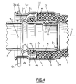
La figure 4 est une vue en coupe axiale du dispositif suivant l'invention assurant la jonction étanche entre le conduit souple et l'embout tubulaire rigide.Figure 4 is an axial sectional view of the device according to the invention ensuring the tight connection between the flexible conduit and the rigid tubular end piece.
Sur la figure 1, on a représenté les différents éléments constituant le dispositif de jonction suivant l'invention, avant leur assemblage. Ces éléments comportent un conduit souple 1 constitué par un tuyau de caoutchouc tel qu'une durit du circuit de refroidissement d'un véhicule automobile, un embout tubulaire rigide 2 tel qu'un embout de raccordement d'un radiateur de véhicule automobile, un élément tubulaire externe 3 ou bague externe, un élément tubulaire interne 4 ou bague interne, un joint d'étanchéité torique 5 et une agrafe élastique 6.In Figure 1, there is shown the various elements constituting the joining device according to the invention, before their assembly. These elements comprise a
Comme il est visible sur les figures 1 et 4, l'embout rigide 2 est constitué par un tube métallique comportant une extrémité d'engagement 2a de forme légèrement tronconique et une partie 2b suivant laquelle la paroi du tube 2 est repoussée vers l'extérieur pour constituer une zone annulaire en saillie radiale par rapport à la surface extérieure de la partie courante du tube 2.As can be seen in FIGS. 1 and 4, the
La saillie annulaire 2b comporte une paroi antérieure tronconique 2c inclinée par rapport à l'axe 7 de l'embout 2 et un talon postérieur 2d sensiblement perpendiculaire à l'axe 7.The
Entre les parties 2a et 2b, l'embout 2 comporte deux parties cylindriques successives 2e et 2f. La partie 2e présente un diamètre extérieur inférieur au diamètre extérieur de la partie 2f, de manière à limiter le frottement du joint au moment du montage.Between the
L'embout 2 comporte de plus une rainure 8 de direction axiale entre son extrémité antérieure et une zone située à l'avant de la saillie annulaire 2b. La rainure 8 peut être réalisée par repoussage de la paroi du tube 2, par exemple par galetage ou par usinage.The
On va maintenant décrire plus en détail les bagues externe 3 et interne 4 en se référant aux figures 1, 2 et 4.We will now describe in more detail the outer 3 and inner 4 rings with reference to FIGS. 1, 2 and 4.
La bague externe est constituée par une virole métallique dont l'extrémité antérieure 3a, légèrement évasée pour faciliter l'engagement du conduit 1 avant le sertissage, est repliée vers l'intérieur contre le conduit souple 1, lors du sertissage de la bague externe 3 et de la bague interne 4 sur le conduit souple 1.The outer ring is constituted by a metal ferrule whose
La bague externe 3 comporte une seconde extrémité 3b opposée à l'extrémité 3a constituant une collerette légèrement en saillie vers l'extérieur et délimitant une gorge 3c réalisée par un léger repoussage de la paroi de la bague externe 3 vers l'intérieur.The
Dans sa partie constituant la gorge 3c, la paroi de la bague externe 3 est traversée par deux fentes 9 s'étendant chacune sur une partie de la périphérie de la bague externe 3, suivant un arc de l'ordre de 120° ou un peu inférieur.In its part constituting the
La bague externe 3 comporte également trois ergots 10 disposés à 120° les uns des autres autour de l'axe de la bague 3 et réalisés par poinçonnage et repoussage vers l'intérieur d'une languette découpée dans la paroi de la bague 3.The
La bague interne 4 comporte une partie antérieure d'engagement 4a de forme légèrement tronconique et une partie 4b constituant l'extrémité opposée de la bague interne 4 dans laquelle la paroi de la bague 4 est repoussée vers l'extérieur pour constituer une partie en saillie radiale et une gorge interne 4c fermée par une collerette repliée vers l'intérieur.The
Dans sa partie située à l'avant de la saillie annulaire 4b, la bague interne 4 comporte deux nervures annulaires 11 en saillie radiale vers l'extérieur sur sa partie située à l'avant de la saillie 4b, de manière à assurer la retenue du conduit souple 1, après sertissage.In its part located at the front of the
La bague interne 4 comporte de plus une partie 12 repoussée vers l'intérieur ayant une forme sensiblement sphérique ou une forme de goutte destinée à assurer l'orientation de la bague intérieure 4 et du conduit souple 1, par rapport à l'embout rigide 2, lors de sa mise en place, par coopération avec la rainure 8 de l'embout 2.The
Sur la figure 3, on a représenté une installation permettant de réaliser la fixation par sertissage d'une partie d'extrémité d'un tuyau souple 1 en caoutchouc entre une bague externe telle que la bague 3 et une bague interne telle que la bague 4 qui ont été décrites précédemment.In Figure 3, there is shown an installation for performing the fixing by crimping an end portion of a
L'installation désignée de manière générale par le repère 13 comporte une unité de sertissage 14 dont le bâti est fixé sur une plateforme 15, un bloc mobile 16 assurant le support et la mise en place de la bague externe du dispositif de jonction, monté mobile sur un rail horizontal 17 fixé sur la plateforme 15, un support 18 fixé sur la plateforme 15, un bloc mobile 19 de support et de mise en place de la bague interne du dispositif de jonction et un bloc mobile 20 de support et de mise en place du conduit souple 1, monté mobile sur un rail horizontal 21 fixé sur la plateforme 15.The installation generally designated by the
L'unité de sertissage 14 comporte dans une disposition circulaire des mors de sertissage 22 montés mobiles dans la direction radiale à l'intérieur du bâti de l'unité de sertissage et un piston 23 monté mobile à l'intérieur du bâti de l'unité de sertissage 14 venant en prise avec les mors 22, par l'intermédiaire de surfaces tronconiques.The
Le déplacement du piston 23 dans un premier sens permet de réaliser le serrage des mors par coopération des surfaces coniques du piston 23 et des mors 22.The displacement of the
Le déplacement du piston 23 dans l'autre sens permet de relâcher la pression exercée sur les mors de sertissage 22.The displacement of the
Le bloc mobile 16 comporte un support tubulaire 25 présentant un logement 25a à son extrémité antérieure, dans lequel peut être placée une bague externe telle que la bague 3 dont on assure le sertissage sur un conduit souple. Le bloc mobile 16 peut être déplacé sur le rail 17 par un vérin, entre une position avancée de chargement représentée sur la figure 3 et une position reculée de sertissage.The
Le bloc mobile 19 sur lequel est fixé un mandrin 26 peut être déplacé sur le rail 24, par l'intermédiaire d'un vérin, entre une position reculée de mise en place d'une bague interne à l'extrémité du mandrin 26 et une position avancée de mise en place de la bague interne à l'intérieur d'un conduit souple 1.The
Le chariot 20 peut être déplacé sur le rail 21, grâce à un vérin, entre une position de chargement d'un tuyau souple 1, comme représenté sur la figure 3, et une position d'engagement du tuyau souple 1 à l'intérieur d'une bague externe 3 placée dans le logement 25a.The
Le fonctionnement de l'installation représentée sur la figure 3 est le suivant.The operation of the installation shown in Figure 3 is as follows.
A l'instant initial, les différents organes de l'installation sont dans leur position représentée sur la figure 3.At the initial instant, the various components of the installation are in their position shown in FIG. 3.
Un tuyau souple 1 tel qu'une durit d'un moteur d'automobile est fixé sur le bloc mobile 20 qui comporte une pince 20a de serrage du tuyau souple 1. La pince de serrage 20a comporte deux mors qui peuvent être rapprochés pour maintenir fermement le tuyau souple 1 ou éloignés l'un de l'autre pour libérer le tuyau souple 1. Une bague externe est placée à l'intérieur du logement 25a du support tubulaire 25 du bloc mobile 16.A
Une bague interne 4 est placée sur la partie d'extrémité du mandrin 26 du bloc mobile 19.An
Le bloc mobile 20 dont la pince 20a se referme sur le tuyau souple 1 est déplacé, de manière à réaliser l'engagement de l'extrémité du conduit souple 1 à l'intérieur de la bague externe 3. L'engagement est facilité par le fait que l'extrémité 3a de la bague externe 3 dirigée vers l'extérieur du logement 25a est légèrement évasée. L'engagement du conduit souple 1 à l'intérieur de la bague externe 3 se termine par la mise en butée de l'extrémité du conduit souple 1 sur les ergots 10 en saillie radiale vers l'intérieur de la bague externe 3.The
Par déplacement vers l'avant du bloc mobile 19, on réalise l'engagement de la bague interne 4 à l'intérieur du conduit souple 1, jusqu'au moment où la partie 4b en saillie radiale vient en butée contre les ergots 10 de la bague externe 3.By moving the
Le bloc mobile 16 est placé en position reculée, de manière que la bague externe 3 dans laquelle est engagé le tuyau souple 1 soit placée en position de sertissage entre les mors 22.The
Les différents composants du dispositif de jonction sont alors dans leur position relative représentée sur la figure 2.The various components of the joining device are then in their relative position shown in FIG. 2.
Ces éléments sont placés dans l'emprise des mors de sertissage 22. Le piston 23 est déplacé vers l'avant de manière à serrer les mors 22 qui réalisent le sertissage de la bague externe 3 comprenant le conduit souple 1 entre celle-ci et la bague interne 4.These elements are placed in the grip of the crimping
Comme il est visible sur la figure 4, à l'issue du sertissage, la partie antérieure de la bague externe 3 est rabattue vers l'intérieur contre le conduit souple 1 et les nervures circulaires 11 pénètrent à l'intérieur du conduit souple 1 déformé élastiquement. On réalise ainsi une fixation efficace par compression du conduit souple 1 entre la bague externe sertie 3 et la bague interne 4.As can be seen in FIG. 4, at the end of crimping, the front part of the
Les blocs mobiles 20, 19, 16 reprennent alors leurs positions initiales, libérant le conduit souple 1. La pince 20a s'ouvre pendant le recul du bloc mobile 20.The
On réalise alors manuellement le montage d'une agrafe 6 sur la bague externe 3.Then a
Comme il est visible sur la figure 1, l'agrafe 6 réalisée sous la forme d'un cavalier comporte deux branches 6a et 6b qui peuvent être écartées l'une de l'autre par déformation élastique du cavalier et qui comportent à leurs extrémités deux parties repliées 6c et 6d.As can be seen in FIG. 1, the
Pour réaliser le montage de l'agrafe 6 sur la bague externe 3 assurant le sertissage du conduit souple 1, on enfile l'agrafe 6 sur la bague externe 3, au niveau de la gorge 3c, de manière à engager chacune des branches 6a et 6b dans une fente 9 traversant la paroi de la bague externe 3.To mount the
Lorsque l'agrafe 6 est totalement engagée sur la bague externe 3, la partie de l'agrafe commune aux branches 6a et 6b vient en appui contre le fond de la gorge 3c.When the
Les branches 6a et 6b pénétrant chacune à l'intérieur de la bague externe 3 à travers une fente 9 sont partiellement en saillie à l'intérieur de la bague 3.The
Les parties 6c et 6d d'extrémité des branches 6a et 6b repliées sur elles-mêmes se trouvent à l'extérieur de la bague externe 3.The
Les branches 6a et 6b de l'agrafe 6 sont légèrement repliées vers l'intérieur, de manière à faire un angle voisin de 30° avec l'axe de symétrie de l'agrafe 6 passant par le centre de la partie arrondie commune aux deux branches 6a et 6b.The
L'espace ménagé entre les branches 6a et 6b introduites à l'intérieur de l'alésage de la bague externe 3 présente une dimension minimale inférieure au diamètre extérieur de la partie en saillie 2b de l'embout rigide 2.The space formed between the
Le montage du conduit souple 1 sur lequel ont été serties les bagues 3 et 4, sur l'embout rigide 2 qui est fixé sur une pièce d'un moteur de véhicule automobile telle que le radiateur, est effectué par simple engagement des bagues externe 3 et interne 4 sur l'embout 2, comme représenté sur la figure 4. Préalablement à l'engagement de l'ensemble constitué par le conduit souple 1 et les bagues 3 et 4, un joint d'étanchéité 5 de forme torique généralement en caoutchouc est placé à l'intérieur de la gorge 4c de la bague interne 4.The
L'engagement de la bague externe 3 est réalisé par l'extrémité de cette bague comportant la collerette 3b.The engagement of the
Le conduit souple 1 sur lequel sont serties les bagues 3 et 4 est engagé sur l'embout 2, dans une orientation telle que la saillie 12 se trouve en coïncidence avec la rainure 8 de l'embout rigide 2.The
L'engagement et le blocage du dispositif de jonction sont ensuite réalisés par simple poussée axiale sur l'ensemble constitué par le conduit souple 1 et les bagues 3 et 4. L'orientation préalable du conduit souple 1 pour son engagement sur l'embout tubulaire rigide 2 est nécessaire, dans la mesure où le conduit souple 1 présente généralement une forme courbe nécessitant sa mise en place dans une orientation particulière par rapport à l'embout rigide.The engagement and blocking of the junction device are then carried out by simple axial thrust on the assembly constituted by the
Lors de l'engagement par poussée axiale du conduit souple 1 et des bagues 3 et 4 sur l'embout rigide 2, les branches 6a et 6b de l'agrafe 6 viennent en contact avec la surface tronconique de la paroi 2c de la partie en saillie 2b du conduit rigide 2, de manière que les branches 6a et 6b s'écartent l'une de l'autre puis se resserrent de nouveau à l'arrière de la paroi 2d de la partie en saillie 2b par élasticité. On réalise ainsi le blocage axial du conduit souple 1 rendu solidaire des bagues 3 et 4 par sertissage, par rapport à l'embout rigide 2.During the engagement by axial thrust of the
La jonction est en outre étanche, du fait de la compression du joint torique 5 entre la gorge 4c de la bague interne 4 et la surface extérieure de l'embout rigide 2.The junction is also sealed, due to the compression of the O-
Le montage de la bague externe 3 et de la bague interne 4 sur l'extrémité de raccordement du conduit souple 1 est réalisé de manière totalement automatique grâce à l'installation de sertissage représentée sur la figure 1.The mounting of the
Le montage de l'agrafe 6 sur la bague externe 3 est réalisé sans difficulté, de manière manuelle, du fait que ce montage est effectué sur une pièce parfaitement accessible.The mounting of the
En outre, le montage de l'ensemble mobile du dispositif de jonction constitué par le conduit souple 1 et les bagues 3 et 4 sur la partie fixe constituée par l'embout rigide 2 est réalisé sans difficulté par simple déplacement axial de l'ensemble mobile par rapport à l'embout fixe, après une simple orientation permettant de mettre en coïncidence la partie en saillie 12 de la bague interne 4 avec la rainure 8 de l'embout fixe 2.In addition, the mobile assembly of the junction device constituted by the
En outre, l'agrafe 6 peut être facilement extraite de la bague externe 3 pour assurer le démontage du dispositif de jonction.In addition, the
Du fait que les branches de l'agrafe sont repliées vers l'intérieur, l'agrafe ne peut être séparée de la bague externe, lors du passage de la partie en saillie de l'embout rigide.Due to the fact that the branches of the clip are folded inwards, the clip cannot be separated from the outer ring, when the projecting part of the rigid end piece passes.
L'invention ne se limite pas au mode de réalisation qui a été décrit.The invention is not limited to the embodiment which has been described.
C'est ainsi qu'on peut imaginer des éléments tubulaires externe et interne dont la forme est différente de celle des bagues 3 et 4 qui ont été décrites précédemment.Thus one can imagine external and internal tubular elements whose shape is different from that of the
L'agrafe engagée dans la bague externe peut être remplacée par tout élément équivalent comportant deux branches engagées dans des fentes de la bague externe et pouvant s'écarter et se rapprocher par élasticité.The clip engaged in the outer ring can be replaced by any equivalent element comprising two branches engaged in slots in the outer ring and which can move apart and come together by elasticity.
Enfin, le dispositif de jonction suivant l'invention peut s'appliquer à tout moyen de raccordement étanche d'un conduit souple et d'un embout rigide d'un circuit destiné à la circulation d'un fluide sous pression.Finally, the joining device according to the invention can be applied to any means of sealed connection of a flexible conduit and a rigid end piece of a circuit intended for the circulation of a pressurized fluid.
Claims (9)
Applications Claiming Priority (2)
| Application Number | Priority Date | Filing Date | Title |
|---|---|---|---|
| FR9304646 | 1993-04-20 | ||
| FR9304646A FR2704296B1 (en) | 1993-04-20 | 1993-04-20 | DEVICE FOR SEALED CONNECTION BETWEEN A FLEXIBLE CONDUIT AND A RIGID TUBULAR END PIECE AND INSTALLATION FOR MOUNTING SUCH A DEVICE. |
Publications (2)
| Publication Number | Publication Date |
|---|---|
| EP0621432A1 true EP0621432A1 (en) | 1994-10-26 |
| EP0621432B1 EP0621432B1 (en) | 1996-09-11 |
Family
ID=9446243
Family Applications (1)
| Application Number | Title | Priority Date | Filing Date |
|---|---|---|---|
| EP94400843A Expired - Lifetime EP0621432B1 (en) | 1993-04-20 | 1994-04-18 | Sealed connection device for a hose and a rigid pipe end |
Country Status (3)
| Country | Link |
|---|---|
| EP (1) | EP0621432B1 (en) |
| DE (1) | DE69400499T2 (en) |
| FR (1) | FR2704296B1 (en) |
Cited By (12)
| Publication number | Priority date | Publication date | Assignee | Title |
|---|---|---|---|---|
| EP0841513A1 (en) * | 1996-11-09 | 1998-05-13 | REHAU AG + Co | Coupling for suction or pressure hoses |
| GB2320542A (en) * | 1996-12-21 | 1998-06-24 | Daimler Benz Ag | An arrangement for connecting two tubular line parts |
| GB2346349A (en) * | 1999-01-02 | 2000-08-09 | Rover Group | Motor vehicle fuel tank assembly |
| FR2839136A1 (en) * | 2002-04-24 | 2003-10-31 | Hutchinson | WATERPROOF CONNECTION DEVICE, PARTICULARLY FOR AN AIR INTAKE CIRCUIT OF A MOTOR VEHICLE ENGINE |
| CN100381743C (en) * | 2003-11-28 | 2008-04-16 | 东海橡胶工业株式会社 | Quick connector |
| CN100424398C (en) * | 2004-04-03 | 2008-10-08 | 亨恩有限及两合股份公司 | Plug-in connection provided with an angle-locking device |
| WO2009015927A1 (en) * | 2007-07-31 | 2009-02-05 | Uponor Innovation Ab | Press fitting for a pipe, in particular plastic pipe or plastic and metal composite pipe |
| FR2965023A1 (en) * | 2010-09-17 | 2012-03-23 | Peugeot Citroen Automobiles Sa | Device for assembling hose and e.g. radiator in engine of motor vehicle, has immobilizing units that are respectively arranged on maintaining and deformable rings to immobilize maintaining ring and to tighten deformable ring on hose |
| WO2016071582A1 (en) * | 2014-11-05 | 2016-05-12 | Hutchinson | Device for coupling a rigid male endpiece to a flexible female pipe, and production method therefor |
| US20160363247A1 (en) * | 2015-06-10 | 2016-12-15 | Ford Global Technologies, Llc | Quick connect system for automotive fluid transport lines |
| CN110220055A (en) * | 2019-07-03 | 2019-09-10 | 广州保瑞医疗技术有限公司 | Tube press machine and adjustment structure |
| AT17372U1 (en) * | 2021-01-20 | 2022-02-15 | Henn Gmbh & Co Kg | Mating connector for connecting components for liquid or gaseous media, and a plug assembly and a method for producing such a mating connector |
Families Citing this family (3)
| Publication number | Priority date | Publication date | Assignee | Title |
|---|---|---|---|---|
| DE19522690A1 (en) * | 1995-06-22 | 1997-01-02 | Henn Gmbh & Co Kg | Plug connection for the connection of pipe and hose lines |
| DE10347928A1 (en) * | 2003-10-15 | 2005-06-02 | Henn Gmbh & Co. Kg | Pipe connecting system comprises plug section on pipe which fits over outlet and has radial rib which projects inwards and fits into groove on outlet extending inwards from its end |
| AT525973B1 (en) * | 2022-07-26 | 2023-10-15 | Henn Gmbh & Co Kg | Connector for connecting lines for liquid or gaseous media |
Citations (9)
| Publication number | Priority date | Publication date | Assignee | Title |
|---|---|---|---|---|
| US3314696A (en) * | 1964-02-11 | 1967-04-18 | Perfecting Service Company | Quick connect coupling |
| US3584902A (en) * | 1969-07-09 | 1971-06-15 | Anchor Coupling Co Inc | Quick-connect safety coupling |
| US4285228A (en) * | 1979-08-20 | 1981-08-25 | Anchor Coupling Co., Inc. | Crimping machine for hose assembly |
| EP0072889A2 (en) * | 1981-08-21 | 1983-03-02 | Stratoflex, Inc. | Improved clip for a fluid coupling |
| FR2628819A1 (en) * | 1988-03-17 | 1989-09-22 | Peugeot | Flexible connection for hose - is used in vehicle cooling system and incorporates external groove in clamping sleeve |
| DE3815171A1 (en) * | 1988-05-04 | 1989-11-09 | Rasmussen Gmbh | PLUG-IN COUPLING TO CONNECT A HOSE TO A PIPE |
| DE3815172C1 (en) * | 1988-05-04 | 1990-03-22 | Rasmussen Gmbh, 6457 Maintal, De | |
| EP0392234A2 (en) * | 1989-04-11 | 1990-10-17 | Hutchinson Gummiwarenfabrik GmbH | Quick acting coupling operable by robots, especially for liquid containing hoses for the connection with radiators or similar aggregates |
| FR2667922A1 (en) * | 1990-10-11 | 1992-04-17 | Peugeot | IMPROVED JOINT DEVICE BETWEEN A FLEXIBLE TUBULAR CONNECTION AND A RIGID TUBULAR END PIECE. |
-
1993
- 1993-04-20 FR FR9304646A patent/FR2704296B1/en not_active Expired - Fee Related
-
1994
- 1994-04-18 EP EP94400843A patent/EP0621432B1/en not_active Expired - Lifetime
- 1994-04-18 DE DE69400499T patent/DE69400499T2/en not_active Expired - Fee Related
Patent Citations (9)
| Publication number | Priority date | Publication date | Assignee | Title |
|---|---|---|---|---|
| US3314696A (en) * | 1964-02-11 | 1967-04-18 | Perfecting Service Company | Quick connect coupling |
| US3584902A (en) * | 1969-07-09 | 1971-06-15 | Anchor Coupling Co Inc | Quick-connect safety coupling |
| US4285228A (en) * | 1979-08-20 | 1981-08-25 | Anchor Coupling Co., Inc. | Crimping machine for hose assembly |
| EP0072889A2 (en) * | 1981-08-21 | 1983-03-02 | Stratoflex, Inc. | Improved clip for a fluid coupling |
| FR2628819A1 (en) * | 1988-03-17 | 1989-09-22 | Peugeot | Flexible connection for hose - is used in vehicle cooling system and incorporates external groove in clamping sleeve |
| DE3815171A1 (en) * | 1988-05-04 | 1989-11-09 | Rasmussen Gmbh | PLUG-IN COUPLING TO CONNECT A HOSE TO A PIPE |
| DE3815172C1 (en) * | 1988-05-04 | 1990-03-22 | Rasmussen Gmbh, 6457 Maintal, De | |
| EP0392234A2 (en) * | 1989-04-11 | 1990-10-17 | Hutchinson Gummiwarenfabrik GmbH | Quick acting coupling operable by robots, especially for liquid containing hoses for the connection with radiators or similar aggregates |
| FR2667922A1 (en) * | 1990-10-11 | 1992-04-17 | Peugeot | IMPROVED JOINT DEVICE BETWEEN A FLEXIBLE TUBULAR CONNECTION AND A RIGID TUBULAR END PIECE. |
Cited By (20)
| Publication number | Priority date | Publication date | Assignee | Title |
|---|---|---|---|---|
| EP0841513A1 (en) * | 1996-11-09 | 1998-05-13 | REHAU AG + Co | Coupling for suction or pressure hoses |
| GB2320542A (en) * | 1996-12-21 | 1998-06-24 | Daimler Benz Ag | An arrangement for connecting two tubular line parts |
| GB2320542B (en) * | 1996-12-21 | 1999-03-03 | Daimler Benz Ag | An arrangement for connecting two tubular line parts |
| US6042154A (en) * | 1996-12-21 | 2000-03-28 | Daimlerchrysler Ag | Arrangement for joining tubular duct sections |
| GB2346349A (en) * | 1999-01-02 | 2000-08-09 | Rover Group | Motor vehicle fuel tank assembly |
| FR2839136A1 (en) * | 2002-04-24 | 2003-10-31 | Hutchinson | WATERPROOF CONNECTION DEVICE, PARTICULARLY FOR AN AIR INTAKE CIRCUIT OF A MOTOR VEHICLE ENGINE |
| WO2003091616A1 (en) * | 2002-04-24 | 2003-11-06 | Hutchinson | Impervious connecting device, in particular for the engine air inlet system of a motor vehicle |
| CN100381743C (en) * | 2003-11-28 | 2008-04-16 | 东海橡胶工业株式会社 | Quick connector |
| CN100424398C (en) * | 2004-04-03 | 2008-10-08 | 亨恩有限及两合股份公司 | Plug-in connection provided with an angle-locking device |
| US9803786B2 (en) | 2007-07-31 | 2017-10-31 | Uponor Innovation Ab | Press fitting for a pipe, in particular plastic pipe or plastic and metal composite pipe |
| WO2009015927A1 (en) * | 2007-07-31 | 2009-02-05 | Uponor Innovation Ab | Press fitting for a pipe, in particular plastic pipe or plastic and metal composite pipe |
| FR2965023A1 (en) * | 2010-09-17 | 2012-03-23 | Peugeot Citroen Automobiles Sa | Device for assembling hose and e.g. radiator in engine of motor vehicle, has immobilizing units that are respectively arranged on maintaining and deformable rings to immobilize maintaining ring and to tighten deformable ring on hose |
| CN107002922A (en) * | 2014-11-05 | 2017-08-01 | 哈金森公司 | Rigid convex end pieces are connected to the equipment and its production method of flexible spill pipeline |
| WO2016071582A1 (en) * | 2014-11-05 | 2016-05-12 | Hutchinson | Device for coupling a rigid male endpiece to a flexible female pipe, and production method therefor |
| CN107002922B (en) * | 2014-11-05 | 2019-03-22 | 哈金森公司 | Rigid convex end pieces are connected to the equipment and its production method of flexible spill pipeline |
| US10865921B2 (en) | 2014-11-05 | 2020-12-15 | Hutchinson | Device for coupling a rigid male endpiece to a flexible female pipe, and production method therefor |
| US20160363247A1 (en) * | 2015-06-10 | 2016-12-15 | Ford Global Technologies, Llc | Quick connect system for automotive fluid transport lines |
| US9909702B2 (en) * | 2015-06-10 | 2018-03-06 | Ford Global Technologies, Llc | Quick connect system for automotive fluid transport lines |
| CN110220055A (en) * | 2019-07-03 | 2019-09-10 | 广州保瑞医疗技术有限公司 | Tube press machine and adjustment structure |
| AT17372U1 (en) * | 2021-01-20 | 2022-02-15 | Henn Gmbh & Co Kg | Mating connector for connecting components for liquid or gaseous media, and a plug assembly and a method for producing such a mating connector |
Also Published As
| Publication number | Publication date |
|---|---|
| FR2704296B1 (en) | 1995-07-21 |
| DE69400499D1 (en) | 1996-10-17 |
| FR2704296A1 (en) | 1994-10-28 |
| DE69400499T2 (en) | 1997-01-02 |
| EP0621432B1 (en) | 1996-09-11 |
Similar Documents
| Publication | Publication Date | Title |
|---|---|---|
| EP0621432B1 (en) | Sealed connection device for a hose and a rigid pipe end | |
| EP0360634B1 (en) | Connection device between a hose coupling and the rigid pipe end of a pressure circuit | |
| EP0488844A1 (en) | Connection device, especially for assembling a hose to a car heat exchanger | |
| EP0501852B1 (en) | Device for fixing a tubular member to a pipe end of a coupling component, especially for a motor vehicle | |
| FR2679313A1 (en) | Device for leaktight clamping for clamping a flexible tube (hose) forcibly mounted inside a tubular connecter (coupling) | |
| FR2556072A1 (en) | FLUID CONNECTION DEVICE | |
| EP0559505B1 (en) | Connection device between a hose coupling and a rigid pipe end, particularly for a vehicle cooling system | |
| FR2862740A1 (en) | Joint device for connecting refrigerant pipes in automotive air-conditioning system, has retaining portions which return to their initial shapes after first pipe section has been completely inserted into second pipe section | |
| FR2629891A1 (en) | PIPE ASSEMBLY CONNECTION PARTICULARLY FOR GAS | |
| EP3356718B1 (en) | Fluid circuit and process to realise such circuit | |
| EP0338880B1 (en) | Coupling-device between a soft joint element and a rigid pipe end for a pressurised fluid system | |
| WO2000079172A1 (en) | Device for sealed connection of fluid conduit, particularly for motor vehicle | |
| EP0480818B1 (en) | Improved connection device between a hose coupling and a rigid pipe end | |
| EP0452172B1 (en) | Quick-mounting clip for automobile heat-exchangers | |
| EP3640516A1 (en) | Quick coupling device | |
| EP0030180A1 (en) | Joining device for pipes | |
| EP0253712A1 (en) | Device for fastening two cylindrical elements, in particular a pipe with a connection and method of mounting | |
| EP0268511B1 (en) | Coupling device for quickly connecting and disconnecting tubular conduits | |
| EP0364380B1 (en) | Coupling device, especially for a high-pressure hydraulic circuit | |
| EP1413815A1 (en) | Coupling for two flared-end pipes | |
| FR2602572A1 (en) | Device for connecting a flexible pipe around a rigid tubular end fitting | |
| EP1008796A2 (en) | Connecting device for detachably connecting a tube to an insert using a coaxial sleeve | |
| FR2810716A1 (en) | Connector for pipes forming part of car exhaust system comprises male and female connectors with conical sections which fit together at their widest part and biconical sleeve with narrower sections outwards which fits over them | |
| FR2672105A1 (en) | Device for fastening a tubular member onto a tubular connection adaptor of a component, particularly of a motor vehicle | |
| FR2628819A1 (en) | Flexible connection for hose - is used in vehicle cooling system and incorporates external groove in clamping sleeve |
Legal Events
| Date | Code | Title | Description |
|---|---|---|---|
| PUAI | Public reference made under article 153(3) epc to a published international application that has entered the european phase |
Free format text: ORIGINAL CODE: 0009012 |
|
| AK | Designated contracting states |
Kind code of ref document: A1 Designated state(s): DE GB IT |
|
| 17P | Request for examination filed |
Effective date: 19940909 |
|
| 17Q | First examination report despatched |
Effective date: 19950720 |
|
| GRAG | Despatch of communication of intention to grant |
Free format text: ORIGINAL CODE: EPIDOS AGRA |
|
| GRAH | Despatch of communication of intention to grant a patent |
Free format text: ORIGINAL CODE: EPIDOS IGRA |
|
| GRAH | Despatch of communication of intention to grant a patent |
Free format text: ORIGINAL CODE: EPIDOS IGRA |
|
| GRAA | (expected) grant |
Free format text: ORIGINAL CODE: 0009210 |
|
| ITF | It: translation for a ep patent filed |
Owner name: GUZZI E RAVIZZA S.R.L. |
|
| AK | Designated contracting states |
Kind code of ref document: B1 Designated state(s): DE GB IT |
|
| REF | Corresponds to: |
Ref document number: 69400499 Country of ref document: DE Date of ref document: 19961017 |
|
| GBT | Gb: translation of ep patent filed (gb section 77(6)(a)/1977) |
Effective date: 19961216 |
|
| PLBE | No opposition filed within time limit |
Free format text: ORIGINAL CODE: 0009261 |
|
| STAA | Information on the status of an ep patent application or granted ep patent |
Free format text: STATUS: NO OPPOSITION FILED WITHIN TIME LIMIT |
|
| 26N | No opposition filed | ||
| REG | Reference to a national code |
Ref country code: GB Ref legal event code: IF02 |
|
| REG | Reference to a national code |
Ref country code: GB Ref legal event code: 746 Effective date: 20070115 |
|
| PGFP | Annual fee paid to national office [announced via postgrant information from national office to epo] |
Ref country code: GB Payment date: 20080326 Year of fee payment: 15 |
|
| PGFP | Annual fee paid to national office [announced via postgrant information from national office to epo] |
Ref country code: DE Payment date: 20080408 Year of fee payment: 15 |
|
| PGFP | Annual fee paid to national office [announced via postgrant information from national office to epo] |
Ref country code: IT Payment date: 20080409 Year of fee payment: 15 |
|
| GBPC | Gb: european patent ceased through non-payment of renewal fee |
Effective date: 20090418 |
|
| PG25 | Lapsed in a contracting state [announced via postgrant information from national office to epo] |
Ref country code: DE Free format text: LAPSE BECAUSE OF NON-PAYMENT OF DUE FEES Effective date: 20091103 |
|
| PG25 | Lapsed in a contracting state [announced via postgrant information from national office to epo] |
Ref country code: GB Free format text: LAPSE BECAUSE OF NON-PAYMENT OF DUE FEES Effective date: 20090418 |
|
| PG25 | Lapsed in a contracting state [announced via postgrant information from national office to epo] |
Ref country code: IT Free format text: LAPSE BECAUSE OF NON-PAYMENT OF DUE FEES Effective date: 20090418 |