EP0622911A2 - Diversity transmission strategy in mobile/indoor cellular radio communications - Google Patents
Diversity transmission strategy in mobile/indoor cellular radio communications Download PDFInfo
- Publication number
- EP0622911A2 EP0622911A2 EP94105877A EP94105877A EP0622911A2 EP 0622911 A2 EP0622911 A2 EP 0622911A2 EP 94105877 A EP94105877 A EP 94105877A EP 94105877 A EP94105877 A EP 94105877A EP 0622911 A2 EP0622911 A2 EP 0622911A2
- Authority
- EP
- European Patent Office
- Prior art keywords
- base station
- antenna
- mobile station
- preferred
- data
- Prior art date
- Legal status (The legal status is an assumption and is not a legal conclusion. Google has not performed a legal analysis and makes no representation as to the accuracy of the status listed.)
- Granted
Links
Images


Classifications
-
- H—ELECTRICITY
- H04—ELECTRIC COMMUNICATION TECHNIQUE
- H04B—TRANSMISSION
- H04B7/00—Radio transmission systems, i.e. using radiation field
- H04B7/02—Diversity systems; Multi-antenna system, i.e. transmission or reception using multiple antennas
-
- H—ELECTRICITY
- H04—ELECTRIC COMMUNICATION TECHNIQUE
- H04B—TRANSMISSION
- H04B7/00—Radio transmission systems, i.e. using radiation field
- H04B7/02—Diversity systems; Multi-antenna system, i.e. transmission or reception using multiple antennas
- H04B7/04—Diversity systems; Multi-antenna system, i.e. transmission or reception using multiple antennas using two or more spaced independent antennas
- H04B7/08—Diversity systems; Multi-antenna system, i.e. transmission or reception using multiple antennas using two or more spaced independent antennas at the receiving station
- H04B7/0802—Diversity systems; Multi-antenna system, i.e. transmission or reception using multiple antennas using two or more spaced independent antennas at the receiving station using antenna selection
- H04B7/0817—Diversity systems; Multi-antenna system, i.e. transmission or reception using multiple antennas using two or more spaced independent antennas at the receiving station using antenna selection with multiple receivers and antenna path selection
-
- H—ELECTRICITY
- H04—ELECTRIC COMMUNICATION TECHNIQUE
- H04B—TRANSMISSION
- H04B7/00—Radio transmission systems, i.e. using radiation field
- H04B7/02—Diversity systems; Multi-antenna system, i.e. transmission or reception using multiple antennas
- H04B7/04—Diversity systems; Multi-antenna system, i.e. transmission or reception using multiple antennas using two or more spaced independent antennas
- H04B7/08—Diversity systems; Multi-antenna system, i.e. transmission or reception using multiple antennas using two or more spaced independent antennas at the receiving station
- H04B7/0802—Diversity systems; Multi-antenna system, i.e. transmission or reception using multiple antennas using two or more spaced independent antennas at the receiving station using antenna selection
- H04B7/0805—Diversity systems; Multi-antenna system, i.e. transmission or reception using multiple antennas using two or more spaced independent antennas at the receiving station using antenna selection with single receiver and antenna switching
- H04B7/0814—Diversity systems; Multi-antenna system, i.e. transmission or reception using multiple antennas using two or more spaced independent antennas at the receiving station using antenna selection with single receiver and antenna switching based on current reception conditions, e.g. switching to different antenna when signal level is below threshold
Definitions
- This invention relates generally to data communications via radio, and in particular to the problem of multipath fading. Specifically, a combination of antenna diversity techniques is utilized at both a base station and a mobile station in a dynamic way to mitigate the effects of multipath fading in the data transmission process.
- a base station In a mobile/indoor cellular radio communication system, a base station usually communicates with multiple mobile stations and functions as a bridge between mobiles and landline networks such as Local Area Networks (LANs).
- LANs Local Area Networks
- One of the major impairments in this radio communication environment is the multipath fading phenomenon.
- Antenna diversity techniques have been used to mitigate this multipath fading phenomenon.
- transmitting or receiving antenna diversity techniques have been utilized in the past.
- U.S. Patent 4,761,822 to Maile discloses a burst-mode two-way communication system in which a plurality of transceivers at a base station share a common antenna arrangement.
- the common antenna arrangement consists of a plurality of antenna branches and antenna branch selection is made by an operative base station transceiver with regard to the received signal strength from a portable transceiver.
- U.S. Patent 4,953,197 to Kalwell, Jr. et al discloses a spatial diversity system in which a post-detection selection diversity scheme is used.
- the selection criteria are link quality, AGC level, and parity check errors.
- the main emphasis is on radio telephone communication applications.
- U.S. Patent 5,065,499 to Gordon et al discloses a switching antenna diversity scheme in which each antenna is coupled with circuitry to measure the instantaneous and average received signal strength. Antennas are switched if the current signal strength of selected antenna falls below a threshold calculated from the average value. Antennas are also switched if no switching occurs during a predetermined elapsed time. After the switch, a measured signal strength value is compared with the previous value and the system switches back to the previous antenna if the previous signal strength is higher.
- U.S. Patent 5,123,029 to Bantz et al which is assigned to the assignee of this invention, discloses a hybrid controlled access and random access schemes using frequency hopping spread spectrum communications technqiues, and which is implemented in an indoor digital data radio communication system between mobile stations and a computer system.
- a hop in the frequency hopping spread spectrum, communication system is subdivided into two intervals so that different media-access protocols can be used in each interval.
- the protocol uses a centralized control scheme in one interval and a decentralized scheme in the other, and the intervals may be varied depending on the load of the system.
- U.S. Patent 5,123,029 is incorporated herein by reference.
- both transmitting and receiving antenna diversity techniques are dynamically combined and coordinated to combat the multipath fading phenomena in a wireless radio communications system. That is, the invention is directed to a strategy for combining the use of a selection antenna diversity technique at a stationary unit such as a base station, and a selection or switching antenna diversity technique at a remote station efficiently, for data packet transmission in a wireless radio communications system.
- antenna diversity techniques are used at both a stationary unit such as a base station and a mobile station in a cooperative way.
- a selection antenna diversity implementation is used at a base station where multiple antenna/transceiver branches are available and post-detection selection can be performed.
- the selection antenna diversity implementation can be used for either micro-diversity or macro-diversity purposes.
- a "preferred antenna" selection strategy is implemented at the base station to select the transmitting antenna. The selection is based on the result of the most recent data transmission or reception. Received signal strength is measured at each antenna/transceiver branch and the information is used in the selection of the "preferred antenna".
- a switching antenna diversity implementation is used at a mobile station where multiple antennas are connected by a switch to a single radio transceiver.
- a "preferred antenna” selection strategy is implemented at the mobile to select the antenna. The selection is based on the result of the most recent data transmission. If the most recent transmission is not successful, another antenna is selected as the "preferred antenna". The preferred antenna is used for both transmission and data reception.
- a selection antenna diversity implementation may also be used at a mobile station where multiple antenna/transceiver branches are available and post-detection selection can be performed.
- a "preferred antenna” selection strategy is implemented at the mobile station to select the transmitting antenna. The selection is based on the result of the most recent data transmission or reception.
- Receiveddata quality is measured at each antenna/transceiver branch and the information is used in the selection of the "preferred antenna". Also, an integration of both the time diversity concept and the antenna diversity concept at both a base and a mobile station may be utilized to select the "preferred antenna” and utilize both the reciprocal and the quasi-static properties of a mobile/indoor radio propagation channel.
- the invention is directed to a strategy to use both base station antenna diversity and mobile station antenna diversity in a cooperative way in a mobile cellular radio communication system.
- Two kinds of antenna diversity techniques are considered.
- the first kind of antenna diversity technique is selection antenna diversity.
- selection antenna diversity it is meant that at a station there are several separate radio transceivers connected to separate antennas which are separated at least by a "fading coherence distance”.
- the “selection” is performed after demodulation and packet buffering when receiving a packet. This means that a station with multiple antennas receives multiple copies of every packet and can choose the good one instead of the bad ones.
- a base station uses only selection antenna diversity.
- the second kind of antenna diversity is switching antenna diversity.
- switching antenna diversity it is meant that at a station there is only one radio transceiver and the transceiver is connected to a switch which leads to separate antennas. In this case, a station receives only one copy of every packet from its selected antenna. In the following, it is assumed that a mobile station can use either switching antenna diversity or selection antenna diversity.
- micro-diversity in which the antennas are close together
- macro-diversity in which the antennas are far apart.
- Micro-diversity combats multipath fading
- macro-diversity has a dual role in combatting multipath fading and shadowing (the situation in which a good path does not exist due to obstruction).
- the antenna and radio transceiver combination at a base station can be treated as a single unit and the unit can be deployed for either micro-diversity or macro-diversity purpose.
- only a micro-diversity scheme is used at a mobile station.
- antenna diversity is that if a signal received at one antenna is affected by multipath fading or shadowing, a signal at another antenna may not be. This depends on the antennas being sufficiently separated in space or orientation. Measurements have indicated that separation by more than half a wavelength, or orthogonal orientation, is sufficient to ensure that the received signals be uncorrelated for achieving micro-diversity.
- two-branch selection antenna diversity two antennas and two radio transceivers
- two-branch switching antenna diversity two antennas and a single radio receiver
- a base station maintains in its memory a "preferred antenna" choice and updates that choice as follows:
- the preferred antenna is always chosen to be the antenna on which the most recent transmission or reception is successful. This is because the propagation characteristics of the path may be constantly changing. Any assumptions about which antenna should be the preferred antenna based on information that is more than a few milliseconds old are not likely to be relevant.
- a "preferred antenna” is maintained and updated in the following way:
- both the mobile station and the base station may be independently switching transmit antennas.
- the base station chooses its "preferred antenna” according to the result of either transmission or reception.
- the mobile station chooses its "preferred antenna” according only to the result of its transmission.
- the mobile station always uses its "preferred antenna” in the process of receiving a data packet from the base station.
- the operation of the base station selection antenna diversity scheme is the same as the one discussed in case I.
- the operation of mobile station selection antenna diversity scheme is analogous to the operation in the base station.
- a mobile station uses and updates its "preferred antenna" choice in the following way:
- FIG. 1 there is shown two antennae 1 and 2, an antenna switch 3, a radio transceiver 4 and a controller 5.
- the transceiver 4 signals the controller 5 at the completion of each packet reception. The signal indicates whether the packet was successfully received or not.
- the controller switches between a plurality of antennae 1,2 by controlling the antenna switch 3. In order not to corrupt the reception of a packet, the controller may switch antennae only between packet receptions, not during the reception of a packet.
- Packet transmission using switching diversity requires the selection of the transmitting antenna by the controller 5 controlling the antenna switch 3. This selection must be done before the controller initiates packet transmission and the switch setting must not be changed until the entire packet has been transmitted.
- FIG. 2 there is shown two antennae 10 and 11, two radio transceivers 12 and 13, two buffers 14 and 15, a selector 17, and a controller 16.
- selection diversity a technique wherein independently received packets are checked for correctness and only the correct packet is selected by the controller for transmission to the rest of the data communications system.
- the received packets are buffered in their entirety in buffers 14 and 15, respectively.
- the transceivers 12 and 13 signal the controller 16 at the completion of each packet reception. The signal indicates which, if any, of the transceivers 12 and 13 successfully received the packet.
- the controller 16 switches between the buffers 14 and 15 to supply the correct packet to the data communications system.
- Packet transmission using selection diversity requires the selection of which transceiver 12 or 13 is to transmit the packet before packet transmission is initiated. This selection is performed by the controller 16 using means which are described in detail later. Either or both of the transceivers may be selected. The packet to be transmitted is loaded into buffers 14 and 15 before transmission is initiated. In an alternative embodiment it may be possible for both transceivers 12 and 13 to share a single buffer for transmission.
- the invention described herein consists of control means for controlling both switching and selection diversity.
- a given system may consist of units with all switching diversity, all selection diversity, or a combination of both.
- stationary units such as base stations which are used to bridge between wireless and wired data networks use selection diversity
- mobile units such as mobile stations use switching diversity.
- mobile stations transmit only to base stations, while base stations transmit to all mobile stations in their vicinity.
- a base station controller 16 which provides signals on lines 20 and 21 for selecting which base station transceiver 13 or 12, respectively, is to transmit to mobile stations, signals on lines 24 and 25 to select which buffers 14 or 15, respectively, should be used for transmission to the rest of the data communication system, and signals 22 and 23 from the base station, transceivers 12 and 13, respectively, indicating their respective success in receiving packets.
- a preferred transceiver table 30 in the memory of base station controller 16 which records which transceiver is preferred for transmission to a particular mobile station. The table 30 shows, for example, that the preferred transceiver for transmitting to mobile station 210 is transceiver 12.
- the base station controller 16 When a packet is received, the base station controller 16 receives signals on either line 22 or line 23 or both. In response to these signals the base station controller 16 activates either line 24 or 25. If both line 22 and 23 are active, the base station controller 16 may activate either line 24 or line 25. In general, it may not activate both lines.
- the base station controller 16 may update the preferred transceiver table 30 of the base station controller 16. If only one of the base station transceivers 12 or 13 was successful in receiving the packet (only one of lines 22 and 23 is active) the preferred transceiver table 30 entry is checked to see if the signal corresponds to the current preferred transceiver as recorded in the preferred transceiver table 30. If it does not, the preferred transceiver table 30 entry is updated.
- FIG.4 is a flow chart which shows the actions of the base station controller 16 upon transmission to a selected mobile station i.
- the base station controller 16 first examines the preferred base station transceiver table 30 at block 40. If mobile station i has not been transmitted to before, the base station controller 16 makes a new entry into the preferred base station table 30 at block 41 with the mobile station number i and with a randomly chosen preferred transceiver.
- the preferred base station transceiver is chosen randomly in order to equalize the loading on the base station transceivers. If a specific base station transceiver were always chosen as the first preferred base station transceiver, that base station transceiver would be used more frequently and might fail more often.
- a retry count is initialized to a predetermined count at block 43 so that there is a limit on transmission retries.
- Transmission is then initiated to the mobile station at block 44 using the preferred base station transceiver.
- the preferred base station transceiver is then switched to receive mode to await an acknowledgement from the mobile station at block 45. If no acknowledgement is received within a specified time, the retry count is decremented at block 46. If the retry count is then zero, this is indicative that the controller 16 has attempted to transmit to the mobile station a predetermined number of times without success, and then returns an indication of its failure on line 47 to the rest of the data communication system. If the retry count is not then zero, the base station controller 16 changes the preferred base station transceiver entry for the selected mobile station in the preferred transceiver table 30 at block 48 and then returns to block 44 and attempts retransmission with the other transceiver.
- the base station controller 16 If an acknowledgement is successfully received within a specified time as indicated at block 49, the base station controller 16 returns an indication of success on line 50 to the rest of the data communication system. The base station controller 16 then checks to see if the preferred base station transceiver was either one of, or the only one to receive the acknowledgement, as shown at block 51. If it was the only one, no further action is taken. If it was not the only one, the base station controller 16 changes the preferred base station transceiver entry in the preferred base station transceiver table 30 at block 52 for the selected mobile station before indicating success.
- the processing at a base station during reception together with the processing shown in FIG. 4 has the effect of using the base station transceiver which was most successful in receiving data from the selected mobile station as the transceiver on which transmission will be first attempted. If no acknowledgement is received, the base station controller 16 tries either transceiver alternately.
- FIG. 5 is shown a mobile station controller 5 with signals on lines 55 and 56 which control which mobile station antenna 1 or 2, respectively, is selected for transmission and reception, and a signal on line 57 from the mobile station transceiver 4 indicating that the last packet reception was a success. Also shown is a mobile station storage means such as a register or table 58 containing the number of the currently preferred mobile station antenna.
- the currently preferred mobile station antenna is antenna 1.
- the mobile station controller 5 When a packet is received the mobile station controller 5 transmits an acknowledgement using the currently preferred mobile station antenna, retained in the preferred mobile station antenna register or table 58. Since the only information available after packet reception is whether the packet was received successfully by the mobile station, that information is not sufficient to determine whether the packet was transmitted from the base station, or whether the packet was noise or interference, so the preferred mobile station antenna is not switched at this time.
- FIG. 6 is a flow chart which shows the actions of the mobile station controller 5 for transmission of a packet to the base station. Transmission from a mobile station is always to the base station. First the preferred mobile station antenna register 58 is inspected at block 60 to determine whether there is a currently preferred mobile station antenna. If not, the mobile station antenna is chosen randomly at block 61 and its number is set into the preferred mobile station antenna register 58. In either event a preferred mobile station antenna is selected at block 62. A retry count is then initialized to a predetermined count at block 63 so there is a limit on transmission retries, and the packet is then transmitted at block 64. An acknowledgement is waited for at block 65.
- the mobile station controller 5 If an acknowledgement is received within a specified period of time, the mobile station controller 5 returns an indication of success on line 66 to the rest of the data communication system. If not, the retry count is decremented and tested against zero at block 67. If zero, the mobile station controller 5 has already tried the maximum number of times to transmit the packet, and returns an indication of failure to the rest of the data communication system on line 68. However, if the retry count is not zero, the contents of the preferred mobile station antenna register or table 58 are changed to select the other antenna at block 69, and a return is made to block 64, and transmission is attempted again.
- the processing shown in FIG. 6 has the effect of using the mobile station antenna which was most successful in receiving the acknowledgement from the base station as the mobile station antenna on which transmission will be attempted. If no acknowledgement is received from the base station, the mobile station controller will try either antenna alternately.
- the base station switches base station transceivers if necessary on transmission. On reception, the mobile station switches mobile station antennas if necessary.
- the function of the mobile station during packet reception is similar to that described above for a base station. If one of the transceivers is successful in receiving a packet and the other is not, the success is recorded in the preferred antenna register 58 of the modified controller 5. (The controller must be modified so as to accept signals on lines 22 and 23 and to generate signals on lines 20 and 21, and lines 24 and 25.) The function of the mobile station is the same as depicted in FIG. 4, except that it is not necessary to look up the destination unit in a table.
- the preferred transceiver register 58 contains the number of the transceiver to be used.
- base station is structured as in FIG. 1, with switching diversity.
- the function of the base station for reception is similar to that described above for mobile stations.
- the base station controller is similar to that of FIG. 5, except that instead of a single preferred antenna register 58 there must be a preferred antenna table 30.
- the function of the base station is similar to that depicted in FIG. 6, except for the need to look up the preferred antenna in table 30, as in FIG. 4.
- the invention is not limited to radio transceiver systems, but can also be used with other wireless data communications systems, for example infrared systems. Such systems do not suffer from multipath-induced Rayleigh fading, but if the separate infrared transceivers or pickups are located some distance from each other and the mobile stations are moving, the invention as described, chooses the best combination of transceivers in the base station and mobile stations.
- selection antenna diversity is used at a base station where multiple antenna/transceiver branches are available and post-detection branch selection is performed by the radio system controller/adapter.
- An antenna/transceiver branch is defined to be a "preferred" one if the most recent data transmission or reception is more successful with this particular antenna/transceiver branch. The preferred antenna is always selected for next data transmission.
- switching antenna diversity or selection antenna diversity can be used at a mobile station.
- switching antenna diversity multiple antennas are connected through a switch to a single radio transceiver at the mobile station.
- an antenna is defined as "preferred” if the most recent data transmission through the antenna is successful.
- a preferred antenna is used for both data transmission and reception.
- An antenna/transceiver branch is defined to be a "preferred" one if the most recent data transmission or reception is more successful with this particular antenna/transceiver branch. The preferred antenna is always selected for next data transmission.
- the best propagation path between the two stations is selected, assuming the multipath channel does not change faster than the speed at which the preferred antennas are dynamically chosen.
Abstract
Description
- This invention relates generally to data communications via radio, and in particular to the problem of multipath fading. Specifically, a combination of antenna diversity techniques is utilized at both a base station and a mobile station in a dynamic way to mitigate the effects of multipath fading in the data transmission process.
- In a mobile/indoor cellular radio communication system, a base station usually communicates with multiple mobile stations and functions as a bridge between mobiles and landline networks such as Local Area Networks (LANs). One of the major impairments in this radio communication environment is the multipath fading phenomenon. Antenna diversity techniques have been used to mitigate this multipath fading phenomenon. However, either transmitting or receiving antenna diversity techniques have been utilized in the past. These techniques have been utilized in a number of patents, each having certain advantages and disadvantages.
- U.S. Patent 4,761,822 to Maile discloses a burst-mode two-way communication system in which a plurality of transceivers at a base station share a common antenna arrangement. The common antenna arrangement consists of a plurality of antenna branches and antenna branch selection is made by an operative base station transceiver with regard to the received signal strength from a portable transceiver.
- U.S. Patent 4,953,197 to Kalwell, Jr. et al discloses a spatial diversity system in which a post-detection selection diversity scheme is used. The selection criteria are link quality, AGC level, and parity check errors. The main emphasis is on radio telephone communication applications.
- U.S. Patent 5,065,499 to Gordon et al discloses a switching antenna diversity scheme in which each antenna is coupled with circuitry to measure the instantaneous and average received signal strength. Antennas are switched if the current signal strength of selected antenna falls below a threshold calculated from the average value. Antennas are also switched if no switching occurs during a predetermined elapsed time. After the switch, a measured signal strength value is compared with the previous value and the system switches back to the previous antenna if the previous signal strength is higher.
- U.S. Patent 5,123,029 to Bantz et al which is assigned to the assignee of this invention, discloses a hybrid controlled access and random access schemes using frequency hopping spread spectrum communications technqiues, and which is implemented in an indoor digital data radio communication system between mobile stations and a computer system. A hop in the frequency hopping spread spectrum, communication system is subdivided into two intervals so that different media-access protocols can be used in each interval. The protocol uses a centralized control scheme in one interval and a decentralized scheme in the other, and the intervals may be varied depending on the load of the system. U.S. Patent 5,123,029 is incorporated herein by reference.
- According to the present invention, both transmitting and receiving antenna diversity techniques are dynamically combined and coordinated to combat the multipath fading phenomena in a wireless radio communications system. That is, the invention is directed to a strategy for combining the use of a selection antenna diversity technique at a stationary unit such as a base station, and a selection or switching antenna diversity technique at a remote station efficiently, for data packet transmission in a wireless radio communications system.
- In a mobile/indoor cellular radio communication environment, antenna diversity techniques are used at both a stationary unit such as a base station and a mobile station in a cooperative way. A selection antenna diversity implementation is used at a base station where multiple antenna/transceiver branches are available and post-detection selection can be performed. The selection antenna diversity implementation can be used for either micro-diversity or macro-diversity purposes. A "preferred antenna" selection strategy is implemented at the base station to select the transmitting antenna. The selection is based on the result of the most recent data transmission or reception. Received signal strength is measured at each antenna/transceiver branch and the information is used in the selection of the "preferred antenna". A switching antenna diversity implementation is used at a mobile station where multiple antennas are connected by a switch to a single radio transceiver. In this method, a "preferred antenna" selection strategy is implemented at the mobile to select the antenna. The selection is based on the result of the most recent data transmission. If the most recent transmission is not successful, another antenna is selected as the "preferred antenna". The preferred antenna is used for both transmission and data reception. A selection antenna diversity implementation may also be used at a mobile station where multiple antenna/transceiver branches are available and post-detection selection can be performed. A "preferred antenna" selection strategy is implemented at the mobile station to select the transmitting antenna. The selection is based on the result of the most recent data transmission or reception. Receiveddata quality is measured at each antenna/transceiver branch and the information is used in the selection of the "preferred antenna". Also, an integration of both the time diversity concept and the antenna diversity concept at both a base and a mobile station may be utilized to select the "preferred antenna" and utilize both the reciprocal and the quasi-static properties of a mobile/indoor radio propagation channel.
-
- FIG. 1
- is a block diagram of an antenna switching diversity system;
- FIG. 2
- is a block diagram of an antenna selection diversity system;
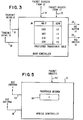
- FIG. 3
- is a block diagram of a stationary station controller;
- FIG. 4
- is a flow chart of a stationary station controller's actions upon transmission from a base station to a mobile station;
- FIG. 5
- is a block diagram of a mobile station controller; and
- FIG. 6
- is a flow chart of a mobile station controller's actions upon transmission from a mobile station to a base station.
- In the following description, the terms stationary unit and base station are used interchangeably. The invention is directed to a strategy to use both base station antenna diversity and mobile station antenna diversity in a cooperative way in a mobile cellular radio communication system. Two kinds of antenna diversity techniques are considered. The first kind of antenna diversity technique is selection antenna diversity. By "selection antenna diversity" it is meant that at a station there are several separate radio transceivers connected to separate antennas which are separated at least by a "fading coherence distance". The "selection" is performed after demodulation and packet buffering when receiving a packet. This means that a station with multiple antennas receives multiple copies of every packet and can choose the good one instead of the bad ones. In the following, it is assumed that a base station uses only selection antenna diversity.
- The second kind of antenna diversity is switching antenna diversity. By "switching antenna diversity" it is meant that at a station there is only one radio transceiver and the transceiver is connected to a switch which leads to separate antennas. In this case, a station receives only one copy of every packet from its selected antenna. In the following, it is assumed that a mobile station can use either switching antenna diversity or selection antenna diversity.
- There are two applications of antenna diversity: micro-diversity, in which the antennas are close together, and macro-diversity, in which the antennas are far apart. Micro-diversity combats multipath fading; macro-diversity has a dual role in combatting multipath fading and shadowing (the situation in which a good path does not exist due to obstruction). The antenna and radio transceiver combination at a base station can be treated as a single unit and the unit can be deployed for either micro-diversity or macro-diversity purpose. On the other hand, only a micro-diversity scheme is used at a mobile station.
- The idea of using antenna diversity is that if a signal received at one antenna is affected by multipath fading or shadowing, a signal at another antenna may not be. This depends on the antennas being sufficiently separated in space or orientation. Measurements have indicated that separation by more than half a wavelength, or orthogonal orientation, is sufficient to ensure that the received signals be uncorrelated for achieving micro-diversity.
- The following is a general description of the invention with respect to two described Cases, with a detailed description following.
- First, a case is considered in which two-branch selection antenna diversity (two antennas and two radio transceivers) is available at a base station and two-branch switching antenna diversity (two antennas and a single radio receiver) is available at a mobile station. The case of more than two branches at either a base station or a mobile station can be easily generalized from the following discussion and is not detailed here.
- In the situation where a base station has multiple diversity antennas a method must be provided for the use of diversity when the base station transmits to a mobile station. The method used is called "time diversity." A base station maintains in its memory a "preferred antenna" choice and updates that choice as follows:
- 1. When a mobile station transmits a data packet to the base station, the base station records which of its two antennas was the more successful in receiving the packet. Here, "more successful" means a successful reception of a data packet with higher received signal energy. If both receptions are unsuccessful, there is no change of the preferred antenna. If both are successful, the antenna with a higher received signal energy becomes the preferred antenna. If only one antenna is successful, that antenna becomes the preferred antenna.
- 2. When the base station transmits to the mobile station, the base station uses the preferred antenna. This choice is sensible because the radio channel is "reciprocal" - it looks the same from both ends, except in the presence of interference, when the same frequency channel is used for both reception and transmission and the delay between the two is short with regard to the rate the multipath channel changes.
- 3. When the mobile station acknowledges receipt of the packet from the base station successfully, the base station does nothing unless one antenna received the acknowledgement more successfully, and that antenna was not the preferred antenna. In this case, the choice of preferred antenna is changed.
- 4. If the acknowledgement from the mobile station is not received, the base station retries the data packet on the other antenna, which now becomes the preferred antenna. Now the base station returns to step 3 until the retry count is exhausted.
- In the method described above, the preferred antenna is always chosen to be the antenna on which the most recent transmission or reception is successful. This is because the propagation characteristics of the path may be constantly changing. Any assumptions about which antenna should be the preferred antenna based on information that is more than a few milliseconds old are not likely to be relevant.
- When a mobile station transmits a data packet to a base station, a "preferred antenna" is maintained and updated in the following way:
- 1. When the mobile station transmits to the base station, it uses its currently preferred antenna. In the beginning, it randomly chooses one antenna as the preferred antenna.
- 2. The mobile station listens for an acknowledgement from the base station using the preferred antenna.
- 3. If the mobile station receives its acknowledgement from the base station, it retains the current preferred antenna. If not, it switches to the other antenna and retries. In this case, the preferred antenna is changed.
- 4. Now the mobile station returns to step 2 until the retry count is exhausted.
- Note that under this strategy, both the mobile station and the base station may be independently switching transmit antennas. The base station chooses its "preferred antenna" according to the result of either transmission or reception. On the other hand, the mobile station chooses its "preferred antenna" according only to the result of its transmission. The mobile station always uses its "preferred antenna" in the process of receiving a data packet from the base station.
- Now, a case is considered in which two-branch selection antenna diversity (two antennas and two radio transceivers) is available at both a base station and a mobile station. The case of more than two branches at both stations can be easily generalized and is not discussed here.
- In this case, the operation of the base station selection antenna diversity scheme is the same as the one discussed in case I. The operation of mobile station selection antenna diversity scheme is analogous to the operation in the base station. A mobile station uses and updates its "preferred antenna" choice in the following way:
- 1. When the base station transmits a data packet to a mobile station, the mobile station records which of its two antennas was the more successful in receiving the packet. Here, by "more successful" is meant a successful reception of a data packet with higher received signal energy. If both receptions are unsuccessful, there is no change of the preferred antenna. If both are successful, the antenna with higher received signal energy becomes the preferred antenna. If only one antenna is successful, that antenna becomes the preferred antenna.
- 2. When the mobile station transmits to the base station, the mobile station uses the preferred antenna.
- 3. When the base station acknowledges receipt of the packet from the mobile station successfully, the mobile station does nothing unless one antenna received the acknowledgement more successfully than the other antenna, and that antenna was not the preferred antenna. In this case, the choice of preferred antenna is changed.
- 4. If the acknowledgement from the base station is not received, the mobile station retries the data packet on the other antenna, which now becomes the preferred antenna. Now the base station returns to step 3 until the retry count is exhausted.
- In the detailed description that follows, it is the case that the only indication of whether a packet has been successfully received is determined at the end of packet reception. The preferred means for this indication is the success or failure of the computation of an error-detecting code, or checksum. In general, this is a powerful and effective means of determining packet reception success. It is more direct than such means as measuring received signal strength, because strong received signals may be corrupted by interference or multipath distortion.
- In FIG. 1 there is shown two
antennae antenna switch 3, aradio transceiver 4 and acontroller 5. This illustrates "switching diversity", a technique wherein signals from a plurality of antennae are switched to a single radio transceiver under the control of a controller. Thetransceiver 4 signals thecontroller 5 at the completion of each packet reception. The signal indicates whether the packet was successfully received or not. The controller switches between a plurality ofantennae antenna switch 3. In order not to corrupt the reception of a packet, the controller may switch antennae only between packet receptions, not during the reception of a packet. - Packet transmission using switching diversity requires the selection of the transmitting antenna by the
controller 5 controlling theantenna switch 3. This selection must be done before the controller initiates packet transmission and the switch setting must not be changed until the entire packet has been transmitted. - In FIG. 2 there is shown two antennae 10 and 11, two
radio transceivers buffers selector 17, and acontroller 16. This illustrates "selection diversity," a technique wherein independently received packets are checked for correctness and only the correct packet is selected by the controller for transmission to the rest of the data communications system. The received packets are buffered in their entirety inbuffers transceivers controller 16 at the completion of each packet reception. The signal indicates which, if any, of thetransceivers controller 16 switches between thebuffers - Packet transmission using selection diversity requires the selection of which transceiver 12 or 13 is to transmit the packet before packet transmission is initiated. This selection is performed by the
controller 16 using means which are described in detail later. Either or both of the transceivers may be selected. The packet to be transmitted is loaded intobuffers transceivers - The invention described herein consists of control means for controlling both switching and selection diversity. A given system may consist of units with all switching diversity, all selection diversity, or a combination of both. In the preferred embodiment, stationary units such as base stations which are used to bridge between wireless and wired data networks use selection diversity, while mobile units such as mobile stations use switching diversity. Again in the preferred embodiment, mobile stations transmit only to base stations, while base stations transmit to all mobile stations in their vicinity.
- In FIG. 3 is shown a
base station controller 16 which provides signals onlines base station transceiver lines 24 and 25 to select which buffers 14 or 15, respectively, should be used for transmission to the rest of the data communication system, and signals 22 and 23 from the base station,transceivers base station controller 16 which records which transceiver is preferred for transmission to a particular mobile station. The table 30 shows, for example, that the preferred transceiver for transmitting tomobile station 210 istransceiver 12. - When a packet is received, the
base station controller 16 receives signals on eitherline 22 orline 23 or both. In response to these signals thebase station controller 16 activates eitherline 24 or 25. If bothline base station controller 16 may activate either line 24 orline 25. In general, it may not activate both lines. - Each time a packet is received, the
base station controller 16 may update the preferred transceiver table 30 of thebase station controller 16. If only one of thebase station transceivers lines - FIG.4 is a flow chart which shows the actions of the
base station controller 16 upon transmission to a selected mobile station i. Thebase station controller 16 first examines the preferred base station transceiver table 30 atblock 40. If mobile station i has not been transmitted to before, thebase station controller 16 makes a new entry into the preferred base station table 30 atblock 41 with the mobile station number i and with a randomly chosen preferred transceiver. The preferred base station transceiver is chosen randomly in order to equalize the loading on the base station transceivers. If a specific base station transceiver were always chosen as the first preferred base station transceiver, that base station transceiver would be used more frequently and might fail more often. Once an entry is found in the preferred base station transceiver table 30 that entry is accessed atblock 42 to determine the preferred base station transceiver for transmission to the mobile station. A retry count is initialized to a predetermined count at block 43 so that there is a limit on transmission retries. - Transmission is then initiated to the mobile station at
block 44 using the preferred base station transceiver. The preferred base station transceiver is then switched to receive mode to await an acknowledgement from the mobile station at block 45. If no acknowledgement is received within a specified time, the retry count is decremented atblock 46. If the retry count is then zero, this is indicative that thecontroller 16 has attempted to transmit to the mobile station a predetermined number of times without success, and then returns an indication of its failure online 47 to the rest of the data communication system. If the retry count is not then zero, thebase station controller 16 changes the preferred base station transceiver entry for the selected mobile station in the preferred transceiver table 30 atblock 48 and then returns to block 44 and attempts retransmission with the other transceiver. - If an acknowledgement is successfully received within a specified time as indicated at
block 49, thebase station controller 16 returns an indication of success online 50 to the rest of the data communication system. Thebase station controller 16 then checks to see if the preferred base station transceiver was either one of, or the only one to receive the acknowledgement, as shown atblock 51. If it was the only one, no further action is taken. If it was not the only one, thebase station controller 16 changes the preferred base station transceiver entry in the preferred base station transceiver table 30 atblock 52 for the selected mobile station before indicating success. - It is seen that the processing at a base station during reception, together with the processing shown in FIG. 4 has the effect of using the base station transceiver which was most successful in receiving data from the selected mobile station as the transceiver on which transmission will be first attempted. If no acknowledgement is received, the
base station controller 16 tries either transceiver alternately. - In FIG. 5 is shown a
mobile station controller 5 with signals onlines mobile station antenna line 57 from themobile station transceiver 4 indicating that the last packet reception was a success. Also shown is a mobile station storage means such as a register or table 58 containing the number of the currently preferred mobile station antenna. The currently preferred mobile station antenna isantenna 1. - When a packet is received the
mobile station controller 5 transmits an acknowledgement using the currently preferred mobile station antenna, retained in the preferred mobile station antenna register or table 58. Since the only information available after packet reception is whether the packet was received successfully by the mobile station, that information is not sufficient to determine whether the packet was transmitted from the base station, or whether the packet was noise or interference, so the preferred mobile station antenna is not switched at this time. - FIG. 6 is a flow chart which shows the actions of the
mobile station controller 5 for transmission of a packet to the base station. Transmission from a mobile station is always to the base station. First the preferred mobilestation antenna register 58 is inspected atblock 60 to determine whether there is a currently preferred mobile station antenna. If not, the mobile station antenna is chosen randomly atblock 61 and its number is set into the preferred mobilestation antenna register 58. In either event a preferred mobile station antenna is selected atblock 62. A retry count is then initialized to a predetermined count atblock 63 so there is a limit on transmission retries, and the packet is then transmitted atblock 64. An acknowledgement is waited for atblock 65. If an acknowledgement is received within a specified period of time, themobile station controller 5 returns an indication of success online 66 to the rest of the data communication system. If not, the retry count is decremented and tested against zero atblock 67. If zero, themobile station controller 5 has already tried the maximum number of times to transmit the packet, and returns an indication of failure to the rest of the data communication system online 68. However, if the retry count is not zero, the contents of the preferred mobile station antenna register or table 58 are changed to select the other antenna atblock 69, and a return is made to block 64, and transmission is attempted again. - It is seen that the processing shown in FIG. 6 has the effect of using the mobile station antenna which was most successful in receiving the acknowledgement from the base station as the mobile station antenna on which transmission will be attempted. If no acknowledgement is received from the base station, the mobile station controller will try either antenna alternately. The combination of the processing shown in FIG. 4 for the base station, together with the processing shown in FIG. 6 for the mobile station, keeps using the same antenna/transceiver pair as long as that is the most successful pair. The base station switches base station transceivers if necessary on transmission. On reception, the mobile station switches mobile station antennas if necessary.
- In an extension of the preferred embodiment, it may be the case that mobile stations are structured as in FIG. 2, with selection diversity. In this case, the function of the mobile station during packet reception is similar to that described above for a base station. If one of the transceivers is successful in receiving a packet and the other is not, the success is recorded in the preferred
antenna register 58 of the modifiedcontroller 5. (The controller must be modified so as to accept signals onlines lines lines 24 and 25.) The function of the mobile station is the same as depicted in FIG. 4, except that it is not necessary to look up the destination unit in a table. The preferredtransceiver register 58 contains the number of the transceiver to be used. - In another extension of the preferred embodiment, it may be the case that base station is structured as in FIG. 1, with switching diversity. In this case, the function of the base station for reception is similar to that described above for mobile stations. The base station controller is similar to that of FIG. 5, except that instead of a single
preferred antenna register 58 there must be a preferred antenna table 30. On transmission, the function of the base station is similar to that depicted in FIG. 6, except for the need to look up the preferred antenna in table 30, as in FIG. 4. - The invention is not limited to radio transceiver systems, but can also be used with other wireless data communications systems, for example infrared systems. Such systems do not suffer from multipath-induced Rayleigh fading, but if the separate infrared transceivers or pickups are located some distance from each other and the mobile stations are moving, the invention as described, chooses the best combination of transceivers in the base station and mobile stations.
- In summary, a strategy has been described to coordinate the use of antenna diversity techniques at both a base station and a mobile station such that the radio system performance degradation due to multipath fading can be reduced in mobile/indoor cellular radio communications.
- In the strategy, in one instance selection antenna diversity is used at a base station where multiple antenna/transceiver branches are available and post-detection branch selection is performed by the radio system controller/adapter. An antenna/transceiver branch is defined to be a "preferred" one if the most recent data transmission or reception is more successful with this particular antenna/transceiver branch. The preferred antenna is always selected for next data transmission.
- On the other hand, either switching antenna diversity or selection antenna diversity can be used at a mobile station. When switching antenna diversity is used, multiple antennas are connected through a switch to a single radio transceiver at the mobile station. In this situation, an antenna is defined as "preferred" if the most recent data transmission through the antenna is successful. A preferred antenna is used for both data transmission and reception.
- When selection antenna diversity is used at a mobile station, the mobile station operates in a similar way as the base station does. An antenna/transceiver branch is defined to be a "preferred" one if the most recent data transmission or reception is more successful with this particular antenna/transceiver branch. The preferred antenna is always selected for next data transmission.
- By combining the independent operations of selection antenna diversity at both a base station and a mobile station, the best propagation path between the two stations is selected, assuming the multipath channel does not change faster than the speed at which the preferred antennas are dynamically chosen.
Claims (12)
- In a diversity transmission system for wireless radio communications between a base station and at least one mobile station, the combination of:
at least two antennas at each of said base station and said at least one mobile station for transmission of data between the respective stations;
means for determining which one of said at least two antennas receives data most successfully, with this antenna being referred to as a preferred antenna;
a preferred antenna storage means in which is stored indica indicative of which antenna is determined to be the preferred antenna; and
a controller at each of said base station and said at least one mobile station which is responsive to the indica stored in the preferred antenna storage means for controlling the transmission of data between the respective stations by selecting the preferred antenna at the respective stations. - The combination claimed in claim 1, including:
means for changing the preferred antenna if an acknowledgement of reception of data isn't received within a predetermined time, or if the acknowledgement is received more successfully on another than said preferred antenna. - The combination claimed in claim 2, including:
means for updating the preferred antenna storage means to reflect the change in preferred antenna. - The combination claimed in at least one of claims 1 to 3, including:
means for signalling a failure when an acknowledgment of reception of the data is not received after a predetermined number of transmissions of the data. - A diversity transmission system for determining the best wireless communication path between at least one base station and at least one mobile station, comprising:
at least two base station antennas for transmission of data between said base station antenna and said mobile station;
means for determining which of said at least two base station antennas receives transmitted data most successfully from said mobile station, with this antenna being referred to as a preferred base station antenna;
a base station storage means for storing indicia indicative of which base station antenna is determined to be the preferred base station antenna;
means responsive to the stored indicia in said base station storage means for selecting the preferred base station antenna for transmission of data from said base station to said mobile station;
means for changing the preferred base station antenna if an acknowledgement of reception of data from said mobile station is not received, or if the acknowledgement is received more successfully on a base station antenna other than said preferred base station antenna;
at least two mobile station antennas for transmission of data between said mobile station and said base station;
means for determining which of said at least two mobile station antennas receives transmitted data most successfully from said base station, with this antenna being referred to as a preferred mobile station antenna;
a mobile station storage means in which is stored indicia indicative of which mobile station antenna is determined to be the preferred mobile station antenna;
means responsive to the stored indicia in said mobile station storage means for selecting the preferred mobile station antenna for transmission of data from said mobile station to said base station;
means for changing the preferred mobile station antenna if an acknowledgement of reception of data isn't received from the base station, or if the acknowledgement is received more successfully on a mobile station antenna other than said preferred antenna; and
means for updating the indicia stored in said mobile station storage means to reflect the change in said preferred mobile station antenna. - The combination claimed in claim 5, including:
means for signalling a failure at said base station when an acknowledgement of reception of data is not received from said mobile station following a predetermined number of transmissions of data from said base station to said mobile station. - The combination claimed in claim 5 or 6, including:
means for signalling a failure at said mobile station when an acknowledgement of reception of data is not received from said base station following a predetermined number of transmissions of data from said mobile station to said base station. - In a diversity transmission system for wireless radio communications between a base station and a plurality of mobile stations, the combination of:
at least two base station antennas at said base station for transmission of data between said base station and said plurality of mobile stations;
at least two base station radio transceivers located at said base station with each such transceiver being connected to a different one of said at least two base station antennas;
means for determining which one of said at least two base station transceivers receives data most successfully from each of said plurality mobile stations, with this transceiver being referred to as a preferred base station transceiver with respect to the mobile station it is receiving data from;
a preferred base station transceiver storage means in said base station controller, in which is stored indica indicative of which base station transceiver is determined to be the preferred base station transceiver with respect to each of said plurality of mobile stations;
means responsive to the stored indicia in said preferred base station transceiver storage means for selecting the preferred base station transceiver for transmission of data from said base station to a given one of said plurality of mobile stations;
means for changing the preferred base station transceiver for said given mobile station if an acknowledgement of reception of data from said given mobile station isn't received, or if the acknowledgement is received more successfully on a base station transceiver other than said preferred transceiver;
means for updating the indicia stored in said preferred base station to reflect the change in preferred antenna for said given mobile station;
at least two mobile station antennas at each of said plurality of mobile stations for transmission of data between said plurality of mobile stations and said base station;
a mobile station radio transceiver located at each of said plurality of mobile stations, which is selectively connected to said at least two mobile station antennas;
means for determining which one of said at least two mobile station antennas at each of said plurality of mobile stations, receives data most successfully from said base station, with this mobile station antenna being referred to as a preferred mobile station antenna;
a preferred mobile station antenna storage means in which is stored indicia indicative of which mobile station antenna is determined to be the preferred mobile station antenna;
means, at each of said plurality of mobile stations which is responsive to the stored indicia in said preferred mobile station antenna storage means for selectively connecting said mobile station radio transceiver to the preferred mobile station antenna for controlling the transmission of data between a mobile station and said base station;
means for signalling a failure at said base station when an acknowledgement of reception of data is not received from a given mobile station following a predetermined number of transmissions of the data from said base station to said given mobile station; and
means for signalling a failure at said given mobile station when an acknowledgement of reception of data is not received from said base station following a predetermined number of transmissions of the data from said given mobile station to said base station. - In a diversity transmission system for wireless radio communications between a base station and a plurality of mobile stations, the combination of:
at least two base station antennas at said base station for transmission of data between said base station and said plurality of mobile stations;
a base station radio transceiver which is selectively connected to said at least two base station antennas;
means for determining which one of said at least two base station antennas receives data most successfully from each of said plurality of mobile stations, with this antenna being referred to as a preferred base station antenna with respect to the mobile station it is receiving data from;
a preferred base station antenna storage means, in which is stored indica indicative of which base station antenna is determined to be the preferred base station antenna with respect to each of said plurality of mobile stations;
means responsive to the stored indicia in said preferred base station antenna storage means for selectively connecting said base station radio transceiver to the preferred antenna for controlling the transmission of data from said base station to teach of said plurality of mobile stations;
means for changing the preferred base station antenna for a given mobile station if an acknowledgement of reception of data from said given mobile station isn't received within a predetermined time, or if the acknowledgement is received more successfully on a base station antenna other than said preferred antenna;
means for updating the indicia stored in said preferred base station antenna storage means to reflect the change in preferred antenna for said given mobile station;
at least two mobile station antennas at each one of said plurality of mobile stations for transmission of data between said plurality of mobile stations and said base station;
a mobile station radio transceiver located at each of said plurality of mobile stations, which is selectively connected to said at least two mobile station antennas;
means for determining which one of said at least two mobile station antennas at each of said plurality of mobile stations receives data most successfully from said base station, with this mobile station antenna being referred to as a preferred mobile station antenna;
a preferred mobile station antenna storage means in which is stored indicia indicative of which mobile station antenna is determined to be the preferred mobile station antenna;
means at each of said plurality of mobile stations, which is responsive to the stored indicia in said preferred mobile station antenna storage means for selectively connecting said mobile station radio transceiver to the preferred mobile station antenna for controlling the transmission of data between a mobile station and said base station;
means for signalling a failure at said base station when an acknowledgement is not received from a given mobile station following a predetermined number of transmissions of the data from said base station to said given mobile station; and
means for signalling a failure at said given mobile station when an acknowledgement is not received from said base station following a predetermined number of transmissions of the data from said given mobile station to said base station. - In a diversity transmission system for wireless radio communications between a base station and a plurality of mobile stations, the combination of:
at least two base station antennas at said base station for transmission of data between said base station and said plurality of mobile stations;
at least two base station radio transceivers located at said base station with each such transceiver being connected to a different one of said at least two base station antennas;
means for determining which one of said at least two base station transceivers receives data most successfully from each of said plurality of mobile stations, with this transceiver being referred to as a preferred base station transceiver with respect to the mobile station it is receiving data from;
a preferred base station transceiver storage means in which is stored indica indicative of which base station transceiver is determined to be the preferred base station transceiver with respect to each of said plurality of mobile stations;
means responsive to the stored indicia in said preferred base transceiver storage means for selecting the preferred base station transceiver for transmission of data from said base station to a given one of said plurality of mobile stations;
means for changing the preferred base station transceiver for said given mobile station if an acknowledgement of reception of data from said given mobile station isn't received within a predetermined time, or if the acknowledgement is received more successfully on a base station transceiver other than said preferred transceiver;
means for updating the indicia stored in said preferred base station transceiver storage means to reflect the change in preferred antenna for said given mobile station;
at least two mobile station antennas at each one of said plurality of mobile stations for transmission of data between said plurality of mobile stations and said base station;
at least two mobile station radio transceivers located at each of said plurality of mobile stations with each such transceiver being connected to a different one of said at least two base mobile antennas;
means for determining which one of said at least two mobile station transceivers receives data most successfully from said base station, with this transceiver being referred to as a preferred mobile station transceiver;
a preferred mobile station transceiver storage means in which is stored indica indicative of which mobile station transceiver is determined to be the preferred mobile station transceiver;
means at each of said plurality of mobile stations which is responsive to the stored indicia in said preferred mobile station transceiver storage means for selectively connecting the preferred mobile station radio transceiver for transmission of data a mobile station to said base station;
means for changing the preferred mobile station transceiver if an acknowledgement of reception of data from said base station isn't received within a predetermined time, or if the acknowledgement is received more successfully on a mobile station transceiver other than said preferred mobile station transceiver;
means for updating the preferred mobile station transceiver storage means to reflect the change in preferred transceiver;
means for signalling a failure at said base station when an acknowledgement is not received from a given mobile station following a predetermined number of transmissions of the data from said base station to said given mobile station; and
means for signalling a failure at said given mobile station when an acknowledgement is not received from said base station following a predetermined number of transmissions of the data from said given mobile station to said base station. - A method of operating a diversity transmission system for wireless radio communications between a base station and at least one mobile station, with at least two antennas at each of said base station and said at least one mobile station for transmission of data between each other, with a controller at each of said base station and said at least one mobile station for controlling the transmission of data between each other, said method comprising the steps of:
determining which one of said at least two antennas receives data most successfully, with this antenna being referred to as a preferred antenna;
storing indica in a preferred antenna storage device in said controller which is indicative of which antenna is determined to be the preferred antenna; and
selecting by said controller at each of said base stations and said at least one mobile station, the preferred antenna for transmission of data, in response to the stored indicia in the respective preferred antenna storage devices. - A method of operating a diversity transmission system for determining the best wireless communications path between a base station having at least two base station antennas and a mobile station having at least two mobile station antennas, said method comprising the steps of:
determining which of said at least two base stations antennas received transmitted data from said mobile station most successfully, with this antenna being referred to as a preferred base station antenna;
storing indicia in a base station storage device which is indicative of which base station antenna is determined to be the preferred base station antenna;
responding to the stored indicia in said base station storage device for selecting the preferred base station antenna for transmission of data from said base station to said mobile station;
changing the preferred base station antenna if an acknowledgement of reception of data is not received from said mobile station, or if an acknowledgement of reception of data is received from said mobile station more successfully on a base station antenna other than said preferred base station antenna;
updating the indicia stored in said base station storage means to reflect the change in the preferred base station antenna;
determining which of said at least two mobile station antennas received transmitted data from said base station most successfully, with this antenna being referred to as a preferred mobile station antenna;
storing indicia in a mobile station storage device which is indicative of which mobile station antenna is determined to be the preferred mobile station antenna;
responding to the stored indicia in said mobile station storage device for selecting the preferred mobile station antenna for transmission of data from said mobile station to said base station;
changing the preferred mobile station antenna if an acknowledgement of reception of data by said base station is not received, or if an acknowledgement is received more successfully on a mobile station antenna other than the presently preferred base station antenna;
updating the indicia stored in said mobile station storage means to reflect the change in preferred mobile station antenna;
signalling a failure at said base station when an acknowledgement of reception of data is not received from said mobile station following a predetermined number of transmissions of data from said base station to said mobile station; and
signalling a failure at said mobile station when an acknowledgement of reception of data is not received from said base station following a predetermined number of transmissions of data from said mobile station to said base station.
Applications Claiming Priority (2)
| Application Number | Priority Date | Filing Date | Title |
|---|---|---|---|
| US08/056,163 US5507035A (en) | 1993-04-30 | 1993-04-30 | Diversity transmission strategy in mobile/indoor cellula radio communications |
| US56163 | 1993-04-30 |
Publications (3)
| Publication Number | Publication Date |
|---|---|
| EP0622911A2 true EP0622911A2 (en) | 1994-11-02 |
| EP0622911A3 EP0622911A3 (en) | 1996-03-06 |
| EP0622911B1 EP0622911B1 (en) | 2002-08-28 |
Family
ID=22002585
Family Applications (1)
| Application Number | Title | Priority Date | Filing Date |
|---|---|---|---|
| EP94105877A Expired - Lifetime EP0622911B1 (en) | 1993-04-30 | 1994-04-15 | Diversity transmission strategy in mobile/indoor cellular radio communications |
Country Status (11)
| Country | Link |
|---|---|
| US (1) | US5507035A (en) |
| EP (1) | EP0622911B1 (en) |
| JP (1) | JP2692779B2 (en) |
| KR (1) | KR970007606B1 (en) |
| CN (1) | CN1068743C (en) |
| AT (1) | ATE223123T1 (en) |
| BR (1) | BR9401624A (en) |
| CA (1) | CA2113734C (en) |
| DE (1) | DE69431219T2 (en) |
| ES (1) | ES2177552T3 (en) |
| TW (1) | TW241418B (en) |
Cited By (37)
| Publication number | Priority date | Publication date | Assignee | Title |
|---|---|---|---|---|
| EP0735701A2 (en) | 1995-03-31 | 1996-10-02 | AT&T IPM Corp. | Switched antenna diversity transmission method and system using ARQ techniques |
| EP0740430A2 (en) * | 1995-04-27 | 1996-10-30 | Sharp Kabushiki Kaisha | Diversity radio communication system |
| EP0744841A2 (en) * | 1995-05-24 | 1996-11-27 | Sony Corporation | Method and apparatus for transmission and reception of burst signals using time diversity and antenna switching |
| WO1997021294A2 (en) * | 1995-12-04 | 1997-06-12 | Aironet Wireless Communications, Inc. | Cellular communication system with dynamically modified data transmission parameters |
| WO1997049199A2 (en) * | 1996-06-18 | 1997-12-24 | Telefonaktiebolaget Lm Ericsson (Publ) | Transmitter diversity assembly and associated method for radio transmitter |
| WO1998036509A1 (en) * | 1997-02-14 | 1998-08-20 | Cellular Telecom, Ltd. | Method and apparatus for wireless communication employing aggregation for digital signals |
| WO1998039860A1 (en) * | 1997-03-04 | 1998-09-11 | Telefonaktiebolaget Lm Ericsson (Publ) | A radio communication system selectively using multicast with variable offset time |
| WO1998054850A2 (en) * | 1997-05-30 | 1998-12-03 | Silicon Wireless Limited | Method and apparatus for wireless communication employing control for confidence metric bandwidth reduction |
| WO1999027659A1 (en) * | 1997-11-21 | 1999-06-03 | Telefonaktiebolaget Lm Ericsson (Publ) | Method and apparatus for receiving radio signals |
| WO1999039455A1 (en) * | 1998-02-02 | 1999-08-05 | Silicon Wireless Limited | Method and apparatus for collector arrays in wireless communications systems |
| WO1999039456A1 (en) * | 1998-02-02 | 1999-08-05 | Silicon Wireless Limited | Method and apparatus for collector arrays of directional antennas co-located with zone managers in wireless communications systems |
| US6006075A (en) * | 1996-06-18 | 1999-12-21 | Telefonaktiebolaget L M Ericsson (Publ) | Method and apparatus for transmitting communication signals using transmission space diversity and frequency diversity |
| US6052408A (en) * | 1995-09-06 | 2000-04-18 | Aironet Wireless Communications, Inc. | Cellular communication system with dynamically modified data transmission parameters |
| US6128512A (en) * | 1995-09-06 | 2000-10-03 | Cisco Systems, Inc. | Cellular communication system with dedicated repeater channels |
| US6132306A (en) * | 1995-09-06 | 2000-10-17 | Cisco Systems, Inc. | Cellular communication system with dedicated repeater channels |
| EP1063789A1 (en) * | 1999-06-23 | 2000-12-27 | Sony International (Europe) GmbH | Transmit and receiving antenna diversity |
| EP1223688A2 (en) * | 2001-01-16 | 2002-07-17 | Matsushita Electric Industrial Co., Ltd. | Receive antenna diversity communications device |
| US6466276B1 (en) * | 1997-09-11 | 2002-10-15 | Nec Corporation | Signal distributing/synthesizing apparatus |
| WO2002082688A1 (en) * | 2001-04-09 | 2002-10-17 | Atheros Communications, Inc. | Method and system for providing antenna diversity |
| WO2002098018A1 (en) * | 2001-06-01 | 2002-12-05 | Koninklijke Philips Electronics N.V. | Antenna diversity arrangement in frequency hopping system |
| KR100422195B1 (en) * | 1995-06-07 | 2004-07-01 | 퀄컴 인코포레이티드 | Linearly communicable antenna system for CDMA communication system |
| EP1445874A1 (en) * | 2001-11-13 | 2004-08-11 | Matsushita Electric Industrial Co., Ltd. | Communication method and radio communication apparatus |
| EP1502122A2 (en) * | 2002-05-06 | 2005-02-02 | Flarion Technologies, INC. | In packet-switched cellular networks |
| EP1353299A3 (en) * | 2002-04-12 | 2006-04-19 | Synegration AG | Method for electronic polling and wireless polling system |
| US7177298B2 (en) | 2000-01-07 | 2007-02-13 | Gopal Chillariga | Dynamic channel allocation in multiple-access communication systems |
| WO2008009015A1 (en) * | 2006-07-14 | 2008-01-17 | Qualcomm Incorporated | Enabling mobile switched antennas |
| US7366089B2 (en) | 2003-10-08 | 2008-04-29 | Atheros Communications, Inc. | Apparatus and method of multiple antenna receiver combining of high data rate wideband packetized wireless communication signals |
| US7385914B2 (en) | 2003-10-08 | 2008-06-10 | Atheros Communications, Inc. | Apparatus and method of multiple antenna transmitter beamforming of high data rate wideband packetized wireless communication signals |
| US7471702B2 (en) | 2005-03-09 | 2008-12-30 | Qualcomm Incorporated | Methods and apparatus for implementing, using, transmitting, and/or receiving signals at least some of which include intentional null tones |
| US7720485B2 (en) | 2006-07-14 | 2010-05-18 | Qualcomm Incorporated | Methods and apparatus related to assignment in a wireless communications system |
| US7826807B2 (en) | 2005-03-09 | 2010-11-02 | Qualcomm Incorporated | Methods and apparatus for antenna control in a wireless terminal |
| US8218690B1 (en) | 2008-09-29 | 2012-07-10 | Qualcomm Atheros, Inc. | Timing offset compensation for high throughput channel estimation |
| US8225186B2 (en) | 2006-07-14 | 2012-07-17 | Qualcomm Incorporated | Ecoding and decoding methods and apparatus for use in a wireless communication system |
| US8325826B2 (en) | 2005-03-09 | 2012-12-04 | Qualcomm Incorporated | Methods and apparatus for transmitting signals facilitating antenna control |
| US8665734B2 (en) | 2002-05-06 | 2014-03-04 | Qualcomm Incorporated | Methods and apparatus for uplink macro-diversity in packet-switched cellular networks |
| US9344897B2 (en) | 2007-03-13 | 2016-05-17 | Qualcomm Incorporated | Estimating timing and frequency information for multiple channel wireless communication systems |
| US9491677B2 (en) | 2002-05-06 | 2016-11-08 | Qualcomm Incorporated | Methods and apparatus for downlink macro-diversity in cellular networks |
Families Citing this family (182)
| Publication number | Priority date | Publication date | Assignee | Title |
|---|---|---|---|---|
| DE4329898A1 (en) | 1993-09-04 | 1995-04-06 | Marcus Dr Besson | Wireless medical diagnostic and monitoring device |
| US6895253B1 (en) * | 1995-03-14 | 2005-05-17 | Lucent Technologies Inc. | Wireless indoor communications using antenna arrays |
| US5944659A (en) * | 1995-11-13 | 1999-08-31 | Vitalcom Inc. | Architecture for TDMA medical telemetry system |
| US5767791A (en) * | 1995-11-13 | 1998-06-16 | Vitalcom | Low-power circuit and method for providing rapid frequency lock in a wireless communications device |
| JP2947157B2 (en) * | 1996-03-07 | 1999-09-13 | 日本電気株式会社 | Transmission space diversity control method and transmission space diversity apparatus |
| US5914933A (en) * | 1996-03-08 | 1999-06-22 | Lucent Technologies Inc. | Clustered OFDM communication system |
| US6005876A (en) * | 1996-03-08 | 1999-12-21 | At&T Corp | Method and apparatus for mobile data communication |
| US5835855A (en) * | 1996-06-12 | 1998-11-10 | 3Com Corporation | Antenna scanning system with low frequency dithering |
| US5990838A (en) * | 1996-06-12 | 1999-11-23 | 3Com Corporation | Dual orthogonal monopole antenna system |
| US5692019A (en) * | 1996-06-17 | 1997-11-25 | Motorola, Inc. | Communication device having antenna switch diversity, and method therefor |
| CA2188845A1 (en) * | 1996-10-25 | 1998-04-25 | Stephen Ross Todd | Diversity Antenna Selection |
| US6169789B1 (en) | 1996-12-16 | 2001-01-02 | Sanjay K. Rao | Intelligent keyboard system |
| US6289209B1 (en) | 1996-12-18 | 2001-09-11 | Micron Technology, Inc. | Wireless communication system, radio frequency communications system, wireless communications method, radio frequency communications method |
| US5842118A (en) * | 1996-12-18 | 1998-11-24 | Micron Communications, Inc. | Communication system including diversity antenna queuing |
| US6104933A (en) * | 1997-06-23 | 2000-08-15 | Telefonaktiebolaget Lm Ericsson | Method and apparatus for control of base stations in macro diversity radio systems |
| FR2765063B1 (en) * | 1997-06-23 | 1999-09-24 | Alsthom Cge Alcatel | BASE STATION WITH A DIVERSITY OF ANTENNAs FOR SENDING UNIDIRECTIONAL CHANNELS, AND CORRESPONDING METHOD OF SENDING A UNIDIRECTIONAL CHANNEL BY A BASE STATION |
| US6633226B1 (en) * | 1997-08-18 | 2003-10-14 | X-Cyte, Inc. | Frequency hopping spread spectrum passive acoustic wave identification device |
| DE19852454B4 (en) * | 1997-12-08 | 2005-11-10 | Fraunhofer-Gesellschaft zur Förderung der angewandten Forschung e.V. | Apparatus and method for improving radio transmission over a radio link between a transmitter and a receiver |
| US6341124B1 (en) | 1998-03-13 | 2002-01-22 | Telefonaktiebolaget Lm Ericsson | Accommodating packet data loss at base stations interfacing between a packet switched network and a CDMA macrodiversity network |
| FI981377A (en) * | 1998-04-24 | 1999-10-25 | Nokia Networks Oy | Sändarantenndiversitet |
| US6373832B1 (en) * | 1998-07-02 | 2002-04-16 | Lucent Technologies Inc. | Code division multiple access communication with enhanced multipath diversity |
| US6535733B1 (en) * | 1998-08-31 | 2003-03-18 | Lucent Technologies Inc. | Measurement radio system for producing operating information for traffic radios |
| FI107202B (en) * | 1999-04-01 | 2001-06-15 | Nokia Networks Oy | Method and apparatus for exchanging parallel signals of a digital data transmission propagation contrast signal |
| US6560443B1 (en) * | 1999-05-28 | 2003-05-06 | Nokia Corporation | Antenna sharing switching circuitry for multi-transceiver mobile terminal and method therefor |
| US7139592B2 (en) * | 1999-06-21 | 2006-11-21 | Arraycomm Llc | Null deepening for an adaptive antenna based communication station |
| US6891820B1 (en) * | 1999-07-06 | 2005-05-10 | Broadcom Corporation | Utilization of the internet protocol to facilitate communication involving mobile devices |
| JP2001069115A (en) * | 1999-08-27 | 2001-03-16 | Matsushita Electric Ind Co Ltd | Ofdm communication device |
| US6496705B1 (en) * | 2000-04-18 | 2002-12-17 | Motorola Inc. | Programmable wireless electrode system for medical monitoring |
| US6441747B1 (en) * | 2000-04-18 | 2002-08-27 | Motorola, Inc. | Wireless system protocol for telemetry monitoring |
| JP3331595B2 (en) * | 2000-06-05 | 2002-10-07 | 日東紡績株式会社 | Indoor environment design system, indoor environment evaluation system, indoor environment design method, and indoor environment evaluation method |
| JP2002009680A (en) * | 2000-06-21 | 2002-01-11 | Matsushita Electric Ind Co Ltd | Receiver and transmitter |
| CA2414309C (en) * | 2000-07-18 | 2006-10-31 | Motorola, Inc. | Wireless electrocardiograph system and method |
| US6647426B2 (en) | 2001-02-26 | 2003-11-11 | Kineto Wireless, Inc. | Apparatus and method for integrating an unlicensed wireless communications system and a licensed wireless communications system |
| US7308263B2 (en) * | 2001-02-26 | 2007-12-11 | Kineto Wireless, Inc. | Apparatus for supporting the handover of a telecommunication session between a licensed wireless system and an unlicensed wireless system |
| GB0105019D0 (en) * | 2001-03-01 | 2001-04-18 | Koninkl Philips Electronics Nv | Antenna diversity in a wireless local area network |
| US6397062B1 (en) * | 2001-03-30 | 2002-05-28 | Bellsouth Intellectual Property Corporation | Multiple antenna test system and method to simultaneously evaluate multiple elevations of potential wireless base station sites |
| GB0110125D0 (en) * | 2001-04-25 | 2001-06-20 | Koninkl Philips Electronics Nv | Radio communication system |
| US7933642B2 (en) * | 2001-07-17 | 2011-04-26 | Rud Istvan | Wireless ECG system |
| JP3923770B2 (en) * | 2001-10-11 | 2007-06-06 | 沖電気工業株式会社 | Handoff control method and handoff control circuit |
| CA2361186A1 (en) * | 2001-11-02 | 2003-05-02 | Ramesh Mantha | System and method for mitigating fading of a signal at a radio receiver |
| US7672274B2 (en) * | 2002-01-11 | 2010-03-02 | Broadcom Corporation | Mobility support via routing |
| US8027637B1 (en) | 2002-01-11 | 2011-09-27 | Broadcom Corporation | Single frequency wireless communication system |
| US7515557B1 (en) | 2002-01-11 | 2009-04-07 | Broadcom Corporation | Reconfiguration of a communication system |
| US6788658B1 (en) | 2002-01-11 | 2004-09-07 | Airflow Networks | Wireless communication system architecture having split MAC layer |
| US7689210B1 (en) * | 2002-01-11 | 2010-03-30 | Broadcom Corporation | Plug-n-playable wireless communication system |
| US6862448B1 (en) * | 2002-01-11 | 2005-03-01 | Broadcom Corporation | Token-based receiver diversity |
| US6760318B1 (en) | 2002-01-11 | 2004-07-06 | Airflow Networks | Receiver diversity in a communication system |
| US7876704B1 (en) | 2002-01-11 | 2011-01-25 | Broadcom Corporation | Tunneling protocols for wireless communications |
| US7149196B1 (en) * | 2002-01-11 | 2006-12-12 | Broadcom Corporation | Location tracking in a wireless communication system using power levels of packets received by repeaters |
| AU2003219882A1 (en) * | 2002-03-01 | 2003-09-16 | Cognio, Inc. | System and method for joint maximal ratio combining |
| US6785520B2 (en) | 2002-03-01 | 2004-08-31 | Cognio, Inc. | System and method for antenna diversity using equal power joint maximal ratio combining |
| US6862456B2 (en) * | 2002-03-01 | 2005-03-01 | Cognio, Inc. | Systems and methods for improving range for multicast wireless communication |
| US6873651B2 (en) * | 2002-03-01 | 2005-03-29 | Cognio, Inc. | System and method for joint maximal ratio combining using time-domain signal processing |
| US6687492B1 (en) * | 2002-03-01 | 2004-02-03 | Cognio, Inc. | System and method for antenna diversity using joint maximal ratio combining |
| US6871049B2 (en) * | 2002-03-21 | 2005-03-22 | Cognio, Inc. | Improving the efficiency of power amplifiers in devices using transmit beamforming |
| FI20020880A0 (en) * | 2002-05-08 | 2002-05-08 | Nokia Corp | Procedure for data communication and data transmission systems |
| US7113498B2 (en) * | 2002-06-05 | 2006-09-26 | Broadcom Corporation | Virtual switch |
| CN102655430A (en) * | 2002-07-30 | 2012-09-05 | 美商智慧财产权授权股份有限公司 | System and method for multiple-input multiple-output (mimo) radio communication |
| US7787572B2 (en) | 2005-04-07 | 2010-08-31 | Rambus Inc. | Advanced signal processors for interference cancellation in baseband receivers |
| US7953423B2 (en) * | 2002-10-18 | 2011-05-31 | Kineto Wireless, Inc. | Messaging in an unlicensed mobile access telecommunications system |
| US7471655B2 (en) * | 2003-10-17 | 2008-12-30 | Kineto Wireless, Inc. | Channel activation messaging in an unlicensed mobile access telecommunications system |
| US7885644B2 (en) | 2002-10-18 | 2011-02-08 | Kineto Wireless, Inc. | Method and system of providing landline equivalent location information over an integrated communication system |
| CN100579313C (en) * | 2002-10-18 | 2010-01-06 | 卡耐特无线有限公司 | Apparatus and method for extending the coverage area of a licensed wireless communication system using an unlicensed wireless communication system |
| US7606190B2 (en) * | 2002-10-18 | 2009-10-20 | Kineto Wireless, Inc. | Apparatus and messages for interworking between unlicensed access network and GPRS network for data services |
| US7640008B2 (en) * | 2002-10-18 | 2009-12-29 | Kineto Wireless, Inc. | Apparatus and method for extending the coverage area of a licensed wireless communication system using an unlicensed wireless communication system |
| US7369859B2 (en) * | 2003-10-17 | 2008-05-06 | Kineto Wireless, Inc. | Method and system for determining the location of an unlicensed mobile access subscriber |
| US7873015B2 (en) | 2002-10-18 | 2011-01-18 | Kineto Wireless, Inc. | Method and system for registering an unlicensed mobile access subscriber with a network controller |
| US7634269B2 (en) * | 2002-10-18 | 2009-12-15 | Kineto Wireless, Inc. | Apparatus and method for extending the coverage area of a licensed wireless communication system using an unlicensed wireless communication system |
| US7349698B2 (en) | 2002-10-18 | 2008-03-25 | Kineto Wireless, Inc. | Registration messaging in an unlicensed mobile access telecommunications system |
| US7565145B2 (en) | 2002-10-18 | 2009-07-21 | Kineto Wireless, Inc. | Handover messaging in an unlicensed mobile access telecommunications system |
| KR20040046322A (en) * | 2002-11-27 | 2004-06-05 | 엘지전자 주식회사 | Signal Processing Apparatus and Method of Multi Input, Multi Output Mobile Communication System |
| SG2011088952A (en) * | 2002-12-04 | 2015-01-29 | Signal Trust For Wireless Innovation | Detection of channel quality indicator |
| US20040204013A1 (en) * | 2002-12-23 | 2004-10-14 | Qing Ma | Communication unit and switch unit |
| US7099678B2 (en) * | 2003-04-10 | 2006-08-29 | Ipr Licensing, Inc. | System and method for transmit weight computation for vector beamforming radio communication |
| JP4193589B2 (en) * | 2003-05-28 | 2008-12-10 | 日本電気株式会社 | Mobile communication terminal and antenna switching method thereof |
| US7079870B2 (en) * | 2003-06-09 | 2006-07-18 | Ipr Licensing, Inc. | Compensation techniques for group delay effects in transmit beamforming radio communication |
| US7595768B2 (en) * | 2003-06-27 | 2009-09-29 | Intel Corporation | Switching schemes for multiple antennas |
| WO2005009069A1 (en) * | 2003-07-10 | 2005-01-27 | Telefonaktiebolaget Lm Ericsson (Publ) | Radio link management based on retransmission request performance |
| US20080132207A1 (en) * | 2003-10-17 | 2008-06-05 | Gallagher Michael D | Service access control interface for an unlicensed wireless communication system |
| US7272397B2 (en) | 2003-10-17 | 2007-09-18 | Kineto Wireless, Inc. | Service access control interface for an unlicensed wireless communication system |
| US7283822B2 (en) * | 2003-10-17 | 2007-10-16 | Kineto Wireless, Inc. | Service access control interface for an unlicensed wireless communication system |
| US7133679B2 (en) * | 2003-10-27 | 2006-11-07 | Nokia Corporation | Radio network planning |
| JP4239828B2 (en) | 2004-01-14 | 2009-03-18 | ソニー株式会社 | Receiving apparatus, receiving method, and program |
| JP4825685B2 (en) * | 2004-01-16 | 2011-11-30 | センサーマティック・エレクトロニクス・エルエルシー | System and method for assigning priority to a reader antenna |
| US7528728B2 (en) * | 2004-03-29 | 2009-05-05 | Impinj Inc. | Circuits for RFID tags with multiple non-independently driven RF ports |
| US7667589B2 (en) * | 2004-03-29 | 2010-02-23 | Impinj, Inc. | RFID tag uncoupling one of its antenna ports and methods |
| US7423539B2 (en) * | 2004-03-31 | 2008-09-09 | Impinj, Inc. | RFID tags combining signals received from multiple RF ports |
| US7957348B1 (en) | 2004-04-21 | 2011-06-07 | Kineto Wireless, Inc. | Method and system for signaling traffic and media types within a communications network switching system |
| JP2005341531A (en) * | 2004-04-27 | 2005-12-08 | Matsushita Electric Ind Co Ltd | Wireless communications system and radio station |
| US8041385B2 (en) | 2004-05-14 | 2011-10-18 | Kineto Wireless, Inc. | Power management mechanism for unlicensed wireless communication systems |
| JP4323381B2 (en) * | 2004-06-03 | 2009-09-02 | Okiセミコンダクタ株式会社 | Wireless receiver |
| US7525926B2 (en) | 2004-08-02 | 2009-04-28 | Atheros Communications, Inc. | Wireless communication using beam forming and diversity |
| US7880683B2 (en) | 2004-08-18 | 2011-02-01 | Ruckus Wireless, Inc. | Antennas with polarization diversity |
| US7652632B2 (en) * | 2004-08-18 | 2010-01-26 | Ruckus Wireless, Inc. | Multiband omnidirectional planar antenna apparatus with selectable elements |
| US8031129B2 (en) | 2004-08-18 | 2011-10-04 | Ruckus Wireless, Inc. | Dual band dual polarization antenna array |
| US7292198B2 (en) * | 2004-08-18 | 2007-11-06 | Ruckus Wireless, Inc. | System and method for an omnidirectional planar antenna apparatus with selectable elements |
| US7933628B2 (en) | 2004-08-18 | 2011-04-26 | Ruckus Wireless, Inc. | Transmission and reception parameter control |
| US7696946B2 (en) * | 2004-08-18 | 2010-04-13 | Ruckus Wireless, Inc. | Reducing stray capacitance in antenna element switching |
| US7899497B2 (en) * | 2004-08-18 | 2011-03-01 | Ruckus Wireless, Inc. | System and method for transmission parameter control for an antenna apparatus with selectable elements |
| US7965252B2 (en) * | 2004-08-18 | 2011-06-21 | Ruckus Wireless, Inc. | Dual polarization antenna array with increased wireless coverage |
| US7193562B2 (en) * | 2004-11-22 | 2007-03-20 | Ruckus Wireless, Inc. | Circuit board having a peripheral antenna apparatus with selectable antenna elements |
| US7940746B2 (en) | 2004-08-24 | 2011-05-10 | Comcast Cable Holdings, Llc | Method and system for locating a voice over internet protocol (VoIP) device connected to a network |
| US8995921B2 (en) * | 2004-09-10 | 2015-03-31 | Interdigital Technology Corporation | Measurement support for a smart antenna in a wireless communication system |
| WO2006030913A1 (en) * | 2004-09-17 | 2006-03-23 | Ntt Docomo, Inc. | Mobile station, base station, and mobile communication method |
| US8619662B2 (en) * | 2004-11-05 | 2013-12-31 | Ruckus Wireless, Inc. | Unicast to multicast conversion |
| US7505447B2 (en) * | 2004-11-05 | 2009-03-17 | Ruckus Wireless, Inc. | Systems and methods for improved data throughput in communications networks |
| TWI391018B (en) | 2004-11-05 | 2013-03-21 | Ruckus Wireless Inc | Throughput enhancement by acknowledgment suppression |
| US8638708B2 (en) * | 2004-11-05 | 2014-01-28 | Ruckus Wireless, Inc. | MAC based mapping in IP based communications |
| US20060239277A1 (en) * | 2004-11-10 | 2006-10-26 | Michael Gallagher | Transmitting messages across telephony protocols |
| US8792414B2 (en) * | 2005-07-26 | 2014-07-29 | Ruckus Wireless, Inc. | Coverage enhancement using dynamic antennas |
| US7358912B1 (en) * | 2005-06-24 | 2008-04-15 | Ruckus Wireless, Inc. | Coverage antenna apparatus with selectable horizontal and vertical polarization elements |
| US7893882B2 (en) | 2007-01-08 | 2011-02-22 | Ruckus Wireless, Inc. | Pattern shaping of RF emission patterns |
| US7646343B2 (en) * | 2005-06-24 | 2010-01-12 | Ruckus Wireless, Inc. | Multiple-input multiple-output wireless antennas |
| WO2006086756A2 (en) * | 2005-02-09 | 2006-08-17 | Kineto Wireless Inc. | Unlicensed mobile access network (uman) system and method |
| US7933598B1 (en) | 2005-03-14 | 2011-04-26 | Kineto Wireless, Inc. | Methods and apparatuses for effecting handover in integrated wireless systems |
| KR20070118264A (en) * | 2005-03-23 | 2007-12-14 | 콸콤 플라리온 테크놀로지스, 인코포레이티드 | Methods and apparatus for using multiple wireless links with a wireless terminal |
| US7756546B1 (en) | 2005-03-30 | 2010-07-13 | Kineto Wireless, Inc. | Methods and apparatuses to indicate fixed terminal capabilities |
| JP2007028511A (en) * | 2005-07-21 | 2007-02-01 | Sony Corp | Radio communication apparatus, radio communication method and its program |
| US7843900B2 (en) | 2005-08-10 | 2010-11-30 | Kineto Wireless, Inc. | Mechanisms to extend UMA or GAN to inter-work with UMTS core network |
| US7515575B1 (en) | 2005-08-26 | 2009-04-07 | Kineto Wireless, Inc. | Intelligent access point scanning with self-learning capability |
| CN101322346A (en) | 2005-12-01 | 2008-12-10 | 鲁库斯无线公司 | On-demand services by wireless base station virtualization |
| US8588220B2 (en) * | 2005-12-30 | 2013-11-19 | L-3 Communications Corporation | Method and apparatus for mitigating port swapping during signal tracking |
| US8165086B2 (en) | 2006-04-18 | 2012-04-24 | Kineto Wireless, Inc. | Method of providing improved integrated communication system data service |
| US9071583B2 (en) * | 2006-04-24 | 2015-06-30 | Ruckus Wireless, Inc. | Provisioned configuration for automatic wireless connection |
| US9769655B2 (en) | 2006-04-24 | 2017-09-19 | Ruckus Wireless, Inc. | Sharing security keys with headless devices |
| WO2007127120A2 (en) | 2006-04-24 | 2007-11-08 | Ruckus Wireless, Inc. | Dynamic authentication in secured wireless networks |
| US7639106B2 (en) * | 2006-04-28 | 2009-12-29 | Ruckus Wireless, Inc. | PIN diode network for multiband RF coupling |
| US20070293178A1 (en) * | 2006-05-23 | 2007-12-20 | Darin Milton | Antenna Control |
| US20080039086A1 (en) * | 2006-07-14 | 2008-02-14 | Gallagher Michael D | Generic Access to the Iu Interface |
| US7852817B2 (en) * | 2006-07-14 | 2010-12-14 | Kineto Wireless, Inc. | Generic access to the Iu interface |
| US20080076425A1 (en) * | 2006-09-22 | 2008-03-27 | Amit Khetawat | Method and apparatus for resource management |
| US7912004B2 (en) * | 2006-07-14 | 2011-03-22 | Kineto Wireless, Inc. | Generic access to the Iu interface |
| US8670725B2 (en) | 2006-08-18 | 2014-03-11 | Ruckus Wireless, Inc. | Closed-loop automatic channel selection |
| US8036664B2 (en) * | 2006-09-22 | 2011-10-11 | Kineto Wireless, Inc. | Method and apparatus for determining rove-out |
| US8204502B2 (en) | 2006-09-22 | 2012-06-19 | Kineto Wireless, Inc. | Method and apparatus for user equipment registration |
| US7995994B2 (en) * | 2006-09-22 | 2011-08-09 | Kineto Wireless, Inc. | Method and apparatus for preventing theft of service in a communication system |
| US8073428B2 (en) | 2006-09-22 | 2011-12-06 | Kineto Wireless, Inc. | Method and apparatus for securing communication between an access point and a network controller |
| US20080076392A1 (en) * | 2006-09-22 | 2008-03-27 | Amit Khetawat | Method and apparatus for securing a wireless air interface |
| CN101170759A (en) * | 2006-10-24 | 2008-04-30 | 国际商业机器公司 | Multi-mode communication terminal, multi-mode communication realizing method |
| US8375804B2 (en) | 2009-05-15 | 2013-02-19 | VISWELL Technology Co., Ltd. | Apparatus for testing bonding strength of electrical connections and frictionless calibration device for the same |
| US20080102752A1 (en) * | 2006-10-30 | 2008-05-01 | The Directv Group, Inc. | Multiple satellite mobile system using multiple antennas |
| US20080111741A1 (en) * | 2006-11-10 | 2008-05-15 | The Directv Group, Inc. | Redundant mobile antenna system and method for operating the same |
| US20080146163A1 (en) * | 2006-12-14 | 2008-06-19 | Motorola, Inc. | Diversity control of multi-mode communication devices |
| US8019331B2 (en) * | 2007-02-26 | 2011-09-13 | Kineto Wireless, Inc. | Femtocell integration into the macro network |
| US7616120B1 (en) | 2007-02-28 | 2009-11-10 | Impinj, Inc. | Multiple RF-port modulator for RFID tag |
| EP3654538B1 (en) * | 2007-05-02 | 2021-09-29 | Tyco Fire & Security GmbH | Wireless communication system |
| US9497229B2 (en) * | 2007-05-16 | 2016-11-15 | At&T Intellectual Property I, L.P. | Methods and apparatus to manage internet protocol (IP) multimedia subsystem (IMS) network capacity |
| US8547899B2 (en) * | 2007-07-28 | 2013-10-01 | Ruckus Wireless, Inc. | Wireless network throughput enhancement through channel aware scheduling |
| US8176378B2 (en) * | 2007-09-07 | 2012-05-08 | Broadcom Corporation | Method and system for a transmitting antenna selection failure recovery mode |
| WO2009039318A1 (en) * | 2007-09-18 | 2009-03-26 | Kineto Wireless, Inc. | Method and system for supporting large number of data paths in an integrated communication system |
| US8355343B2 (en) * | 2008-01-11 | 2013-01-15 | Ruckus Wireless, Inc. | Determining associations in a mesh network |
| US20090265542A1 (en) * | 2008-04-18 | 2009-10-22 | Amit Khetawat | Home Node B System Architecture |
| US9467308B2 (en) * | 2008-08-01 | 2016-10-11 | At&T Intellectual Property I, L.P. | Methods and apparatus to control synchronization in voice over internet protocol networks after catastrophes |
| EP2316245A1 (en) * | 2008-08-15 | 2011-05-04 | Kineto Wireless, Inc. | Method and apparatus for inter home node b cell update handling |
| JP5175776B2 (en) * | 2009-03-04 | 2013-04-03 | アズビル株式会社 | Wireless communication device |
| US8217843B2 (en) * | 2009-03-13 | 2012-07-10 | Ruckus Wireless, Inc. | Adjustment of radiation patterns utilizing a position sensor |
| US8698675B2 (en) | 2009-05-12 | 2014-04-15 | Ruckus Wireless, Inc. | Mountable antenna elements for dual band antenna |
| US20100302991A1 (en) * | 2009-06-02 | 2010-12-02 | Qualcomm Incorporated | System and process for transmit diversity in satellite phones |
| CN102763378B (en) * | 2009-11-16 | 2015-09-23 | 鲁库斯无线公司 | Set up and there is wired and mesh network that is wireless link |
| US9979626B2 (en) | 2009-11-16 | 2018-05-22 | Ruckus Wireless, Inc. | Establishing a mesh network with wired and wireless links |
| JP5351782B2 (en) * | 2010-01-18 | 2013-11-27 | アズビル株式会社 | Wireless communication device |
| TWI397276B (en) * | 2010-06-03 | 2013-05-21 | Univ Nat Chiao Tung | System and method for wireless transmitting and receiving information |
| US9407012B2 (en) | 2010-09-21 | 2016-08-02 | Ruckus Wireless, Inc. | Antenna with dual polarization and mountable antenna elements |
| WO2012151224A2 (en) | 2011-05-01 | 2012-11-08 | Ruckus Wireless, Inc. | Remote cable access point reset |
| US8761701B2 (en) * | 2011-07-13 | 2014-06-24 | Apple Inc. | Selective receive diversity in a mobile wireless device |
| US8756668B2 (en) | 2012-02-09 | 2014-06-17 | Ruckus Wireless, Inc. | Dynamic PSK for hotspots |
| US10186750B2 (en) | 2012-02-14 | 2019-01-22 | Arris Enterprises Llc | Radio frequency antenna array with spacing element |
| US9634403B2 (en) | 2012-02-14 | 2017-04-25 | Ruckus Wireless, Inc. | Radio frequency emission pattern shaping |
| US9092610B2 (en) | 2012-04-04 | 2015-07-28 | Ruckus Wireless, Inc. | Key assignment for a brand |
| US10142007B2 (en) * | 2012-07-19 | 2018-11-27 | Intel Deutschland Gmbh | Radio communication devices and methods for controlling a radio communication device |
| US9570799B2 (en) | 2012-09-07 | 2017-02-14 | Ruckus Wireless, Inc. | Multiband monopole antenna apparatus with ground plane aperture |
| US9179336B2 (en) | 2013-02-19 | 2015-11-03 | Mimosa Networks, Inc. | WiFi management interface for microwave radio and reset to factory defaults |
| EP2974045A4 (en) | 2013-03-15 | 2016-11-09 | Ruckus Wireless Inc | Low-band reflector for dual band directional antenna |
| US9998246B2 (en) | 2014-03-13 | 2018-06-12 | Mimosa Networks, Inc. | Simultaneous transmission on shared channel |
| DE102015106405A1 (en) * | 2015-04-27 | 2016-10-27 | Intel IP Corporation | METHOD AND DEVICES BASED ON DYNAMIC RECEPTION DIVERSITY |
| KR102353333B1 (en) | 2015-07-20 | 2022-01-19 | 삼성전자 주식회사 | Apparatus and method for antenna selection of multiple antenna |
| US10587329B2 (en) * | 2017-09-22 | 2020-03-10 | Qualcomm Incorporated | Transmit antenna diversity in radio front end architectures |
| US11714127B2 (en) | 2018-06-12 | 2023-08-01 | International Business Machines Corporation | On-chip spread spectrum characterization |
| US11146307B1 (en) * | 2020-04-13 | 2021-10-12 | International Business Machines Corporation | Detecting distortion in spread spectrum signals |
| US11789161B2 (en) | 2020-07-14 | 2023-10-17 | Spirent Communications Plc | Accuracy of a GNSS receiver that has a non-directional antenna |
| US11287531B2 (en) * | 2020-07-14 | 2022-03-29 | Spirent Communications, Plc | Architecture for providing forecasts of GNSS obscuration and multipath |
| US11693446B2 (en) | 2021-10-20 | 2023-07-04 | International Business Machines Corporation | On-chip spread spectrum synchronization between spread spectrum sources |
Citations (2)
| Publication number | Priority date | Publication date | Assignee | Title |
|---|---|---|---|---|
| EP0352787A2 (en) * | 1988-07-28 | 1990-01-31 | Motorola, Inc. | High bit rate communication system for overcoming multipath |
| JPH0338933A (en) * | 1989-07-06 | 1991-02-20 | Oki Electric Ind Co Ltd | Space diversity system |
Family Cites Families (11)
| Publication number | Priority date | Publication date | Assignee | Title |
|---|---|---|---|---|
| GB1578469A (en) * | 1977-11-05 | 1980-11-05 | Marconi Co Ltd | Tropospheric scatter radio communications systems |
| US4513412A (en) * | 1983-04-25 | 1985-04-23 | At&T Bell Laboratories | Time division adaptive retransmission technique for portable radio telephones |
| GB8521159D0 (en) * | 1985-08-23 | 1985-10-02 | Pa Consulting Services | Two-way radio communications system |
| US5065449A (en) * | 1987-08-03 | 1991-11-12 | Orion Industries | Booster diversity receiving system usable with cellular booster |
| US5097484A (en) * | 1988-10-12 | 1992-03-17 | Sumitomo Electric Industries, Ltd. | Diversity transmission and reception method and equipment |
| JP2735586B2 (en) * | 1988-10-12 | 1998-04-02 | 科学技術振興事業団 | Diversity wireless communication method and wireless device using diversity wireless communication method |
| US4953197A (en) * | 1988-12-08 | 1990-08-28 | International Mobile Machines Corporation | Combination spatial diversity system |
| US5203010A (en) * | 1990-11-13 | 1993-04-13 | Motorola, Inc. | Radio telephone system incorporating multiple time periods for communication transfer |
| US5373548A (en) * | 1991-01-04 | 1994-12-13 | Thomson Consumer Electronics, Inc. | Out-of-range warning system for cordless telephone |
| US5123029A (en) * | 1991-06-21 | 1992-06-16 | International Business Machines Corporation | Broadcast-initiated bipartite frame multi-access protocol |
| JP2696280B2 (en) * | 1991-08-13 | 1998-01-14 | 松下電器産業株式会社 | Wireless data transmission method |
-
1993
- 1993-04-30 US US08/056,163 patent/US5507035A/en not_active Expired - Lifetime
-
1994
- 1994-01-19 CA CA002113734A patent/CA2113734C/en not_active Expired - Fee Related
- 1994-03-10 JP JP6039477A patent/JP2692779B2/en not_active Expired - Fee Related
- 1994-03-30 KR KR1019940006480A patent/KR970007606B1/en not_active IP Right Cessation
- 1994-03-30 CN CN94103798A patent/CN1068743C/en not_active Expired - Lifetime
- 1994-04-15 EP EP94105877A patent/EP0622911B1/en not_active Expired - Lifetime
- 1994-04-15 AT AT94105877T patent/ATE223123T1/en not_active IP Right Cessation
- 1994-04-15 ES ES94105877T patent/ES2177552T3/en not_active Expired - Lifetime
- 1994-04-15 DE DE69431219T patent/DE69431219T2/en not_active Expired - Lifetime
- 1994-04-27 BR BR9401624A patent/BR9401624A/en not_active IP Right Cessation
- 1994-06-22 TW TW083105659A patent/TW241418B/zh not_active IP Right Cessation
Patent Citations (2)
| Publication number | Priority date | Publication date | Assignee | Title |
|---|---|---|---|---|
| EP0352787A2 (en) * | 1988-07-28 | 1990-01-31 | Motorola, Inc. | High bit rate communication system for overcoming multipath |
| JPH0338933A (en) * | 1989-07-06 | 1991-02-20 | Oki Electric Ind Co Ltd | Space diversity system |
Non-Patent Citations (2)
| Title |
|---|
| 39TH IEEE VEHICULAR TECHNOLOGY CONFERENCE, vol. 1, 1 - 3 May 1989 SAN FRANCISCO, CALIFORNIA, pages 50-55, TSUNEKAWA K. 'DIVERSITY ANTENNAS FOR PORTABLE TELEPHONES' * |
| PATENT ABSTRACTS OF JAPAN vol. 015 no. 175 (E-1063) ,2 May 1991 & JP-A-03 038933 (OKI ELECTRIC IND CO LTD) 20 February 1991, * |
Cited By (88)
| Publication number | Priority date | Publication date | Assignee | Title |
|---|---|---|---|---|
| EP0735701A2 (en) | 1995-03-31 | 1996-10-02 | AT&T IPM Corp. | Switched antenna diversity transmission method and system using ARQ techniques |
| EP0735701A3 (en) * | 1995-03-31 | 2000-10-04 | AT&T IPM Corp. | Switched antenna diversity transmission method and system using ARQ techniques |
| US5799245A (en) * | 1995-04-27 | 1998-08-25 | Sharp Kabushiki Kaisha | Cooperative diversity antenna switching on transmitter and receiver side |
| EP0740430A2 (en) * | 1995-04-27 | 1996-10-30 | Sharp Kabushiki Kaisha | Diversity radio communication system |
| EP0740430A3 (en) * | 1995-04-27 | 1997-01-15 | Sharp Kk | Diversity radio communication system |
| EP0744841A3 (en) * | 1995-05-24 | 1999-09-29 | Sony Corporation | Method and apparatus for transmission and reception of burst signals using time diversity and antenna switching |
| EP0744841A2 (en) * | 1995-05-24 | 1996-11-27 | Sony Corporation | Method and apparatus for transmission and reception of burst signals using time diversity and antenna switching |
| KR100422195B1 (en) * | 1995-06-07 | 2004-07-01 | 퀄컴 인코포레이티드 | Linearly communicable antenna system for CDMA communication system |
| US6132306A (en) * | 1995-09-06 | 2000-10-17 | Cisco Systems, Inc. | Cellular communication system with dedicated repeater channels |
| US6128512A (en) * | 1995-09-06 | 2000-10-03 | Cisco Systems, Inc. | Cellular communication system with dedicated repeater channels |
| US5950124A (en) * | 1995-09-06 | 1999-09-07 | Telxon Corporation | Cellular communication system with dynamically modified data transmission parameters |
| US6052408A (en) * | 1995-09-06 | 2000-04-18 | Aironet Wireless Communications, Inc. | Cellular communication system with dynamically modified data transmission parameters |
| WO1997021294A3 (en) * | 1995-12-04 | 1997-08-28 | Aironet Wireless Communication | Cellular communication system with dynamically modified data transmission parameters |
| WO1997021294A2 (en) * | 1995-12-04 | 1997-06-12 | Aironet Wireless Communications, Inc. | Cellular communication system with dynamically modified data transmission parameters |
| US6212242B1 (en) | 1996-06-18 | 2001-04-03 | Telefonaktiebolaget Lm Ericsson (Publ) | Method and apparatus for transmitting communication signals using transmission space diversity and frequency diversity |
| WO1997049199A2 (en) * | 1996-06-18 | 1997-12-24 | Telefonaktiebolaget Lm Ericsson (Publ) | Transmitter diversity assembly and associated method for radio transmitter |
| US6243565B1 (en) | 1996-06-18 | 2001-06-05 | Telefonaktiebolaget Lm Ericsson (Publ) | Method and apparatus for transmitting communication signals using frequency and polarization diversity |
| WO1997049199A3 (en) * | 1996-06-18 | 1998-02-05 | Ericsson Telefon Ab L M | Transmitter diversity assembly and associated method for radio transmitter |
| US6006075A (en) * | 1996-06-18 | 1999-12-21 | Telefonaktiebolaget L M Ericsson (Publ) | Method and apparatus for transmitting communication signals using transmission space diversity and frequency diversity |
| WO1998036509A1 (en) * | 1997-02-14 | 1998-08-20 | Cellular Telecom, Ltd. | Method and apparatus for wireless communication employing aggregation for digital signals |
| US5930248A (en) * | 1997-03-04 | 1999-07-27 | Telefonaktiebolaget Lm Ericsson | Radio communication system selectively using multicast with variable offset time |
| AU731902B2 (en) * | 1997-03-04 | 2001-04-05 | Telefonaktiebolaget Lm Ericsson (Publ) | A radio communication system selectively using multicast with variable offset time |
| WO1998039860A1 (en) * | 1997-03-04 | 1998-09-11 | Telefonaktiebolaget Lm Ericsson (Publ) | A radio communication system selectively using multicast with variable offset time |
| WO1998054850A2 (en) * | 1997-05-30 | 1998-12-03 | Silicon Wireless Limited | Method and apparatus for wireless communication employing control for confidence metric bandwidth reduction |
| WO1998054850A3 (en) * | 1997-05-30 | 1999-05-14 | Silicon Wireless Limited | Method and apparatus for wireless communication employing control for confidence metric bandwidth reduction |
| US6466276B1 (en) * | 1997-09-11 | 2002-10-15 | Nec Corporation | Signal distributing/synthesizing apparatus |
| WO1999027659A1 (en) * | 1997-11-21 | 1999-06-03 | Telefonaktiebolaget Lm Ericsson (Publ) | Method and apparatus for receiving radio signals |
| US6650910B1 (en) | 1997-11-21 | 2003-11-18 | Telefonaktiebolaget Lm Ericsson | Methods and apparatus in antenna diversity systems for estimation of direction of arrival |
| WO1999039455A1 (en) * | 1998-02-02 | 1999-08-05 | Silicon Wireless Limited | Method and apparatus for collector arrays in wireless communications systems |
| WO1999039456A1 (en) * | 1998-02-02 | 1999-08-05 | Silicon Wireless Limited | Method and apparatus for collector arrays of directional antennas co-located with zone managers in wireless communications systems |
| EP1063789A1 (en) * | 1999-06-23 | 2000-12-27 | Sony International (Europe) GmbH | Transmit and receiving antenna diversity |
| US6370369B1 (en) | 1999-06-23 | 2002-04-09 | Sony International (Europe) Gmbh | Network device and method employing omni-directional and directional antennas |
| US7177298B2 (en) | 2000-01-07 | 2007-02-13 | Gopal Chillariga | Dynamic channel allocation in multiple-access communication systems |
| US7643423B2 (en) | 2000-01-07 | 2010-01-05 | Gopal Chillariga | Dynamic channel allocation in multiple-access communication systems |
| EP1223688A2 (en) * | 2001-01-16 | 2002-07-17 | Matsushita Electric Industrial Co., Ltd. | Receive antenna diversity communications device |
| EP1223688A3 (en) * | 2001-01-16 | 2003-10-22 | Matsushita Electric Industrial Co., Ltd. | Receive antenna diversity communications device |
| US7035612B2 (en) | 2001-01-16 | 2006-04-25 | Matsushita Electric Industrial Co., Ltd. | Antenna diversity communications device |
| WO2002082688A1 (en) * | 2001-04-09 | 2002-10-17 | Atheros Communications, Inc. | Method and system for providing antenna diversity |
| WO2002098018A1 (en) * | 2001-06-01 | 2002-12-05 | Koninklijke Philips Electronics N.V. | Antenna diversity arrangement in frequency hopping system |
| US8891678B2 (en) | 2001-11-13 | 2014-11-18 | Wi-Fi One, Llc | Receiving apparatus and receiving method |
| US8705656B2 (en) | 2001-11-13 | 2014-04-22 | Panasonic Corporation | Transmission and reception apparatus and method |
| US11223457B2 (en) | 2001-11-13 | 2022-01-11 | Panasonic Intellectual Property Corporation Of America | Transmission and reception signal processor and method |
| US11218266B2 (en) | 2001-11-13 | 2022-01-04 | Redwood Technologies, Llc | Methods and apparatus for transmitting modulation signals |
| US11115166B2 (en) | 2001-11-13 | 2021-09-07 | Wi-Fi One, Llc | Radio transmission apparatus and methods for transmitting a single or a plurality of modulation signals from one or more antenna |
| US10924241B2 (en) | 2001-11-13 | 2021-02-16 | Wi-Fi One, Llc | Methods and apparatus for transmitting modulation signals |
| US10651993B2 (en) | 2001-11-13 | 2020-05-12 | Wi-Fi One, Llc | Methods and apparatus for transmitting modulation signals |
| US10630443B2 (en) | 2001-11-13 | 2020-04-21 | Wi-Fi One, Llc | Radio transmission apparatus and methods |
| US10491351B2 (en) | 2001-11-13 | 2019-11-26 | Panasonic Intellectual Property Corporation Of America | Transmission and reception signal processor and method |
| US10355841B2 (en) | 2001-11-13 | 2019-07-16 | Wi-Fi One, Llc | Methods and apparatus for transmitting modulation signals |
| US10341071B2 (en) | 2001-11-13 | 2019-07-02 | Wi-Fi One, Llc | Radio transmission apparatus and methods |
| US10263749B2 (en) | 2001-11-13 | 2019-04-16 | Panasonic Intellectual Property Corporation Of America | Transmission and reception signal processor and method |
| EP1445874A4 (en) * | 2001-11-13 | 2011-01-26 | Panasonic Corp | Communication method and radio communication apparatus |
| US7974371B2 (en) | 2001-11-13 | 2011-07-05 | Panasonic Corporation | Communication method and radio communication apparatus |
| US8155224B2 (en) | 2001-11-13 | 2012-04-10 | Panasonic Corporation | Transmission method, transmission apparatus, and reception apparatus |
| US10033551B2 (en) | 2001-11-13 | 2018-07-24 | Panasonic Intellectual Property Corporation Of America | Transmission and reception signal processor and method |
| US10003443B2 (en) | 2001-11-13 | 2018-06-19 | Wi-Fi One, Llc | Methods and apparatus for transmitting modulation signals |
| US8229026B2 (en) | 2001-11-13 | 2012-07-24 | Panasonic Corporation | Processor and processing method for signal transmission |
| US9735986B2 (en) | 2001-11-13 | 2017-08-15 | Panasonic Intellectual Property Corporation Of America | Transmission and reception apparatus and method |
| US8428182B2 (en) | 2001-11-13 | 2013-04-23 | Panasonic Corporation | Communication method and radio communication apparatus |
| US8446973B2 (en) | 2001-11-13 | 2013-05-21 | Panasonic Corporation | Transmission and reception apparatus and method |
| US9647856B2 (en) | 2001-11-13 | 2017-05-09 | Wi-Fi One, Llc | Transmission apparatus and transmission method |
| US8594242B2 (en) | 2001-11-13 | 2013-11-26 | Panasonic Corporation | Method of receiving modulation symbols |
| US9628300B2 (en) | 2001-11-13 | 2017-04-18 | Wi-Fi One, Llc | Method and signal generating apparatus for generating modulation signals |
| US9363124B2 (en) | 2001-11-13 | 2016-06-07 | Panasonic Intellectual Property Corporation Of America | Transmission and reception signal processor and method |
| US9160596B2 (en) | 2001-11-13 | 2015-10-13 | Panasonic Intellectual Property Corporation Of America | Transmission and reception signal processor and method |
| US8744005B2 (en) | 2001-11-13 | 2014-06-03 | Panasonic Corporation | Method and apparatus for generating modulation signals |
| EP1445874A1 (en) * | 2001-11-13 | 2004-08-11 | Matsushita Electric Industrial Co., Ltd. | Communication method and radio communication apparatus |
| US8934578B2 (en) | 2001-11-13 | 2015-01-13 | Wi-Fi One, Llc | Method of demodulating modulation signals |
| US8982998B2 (en) | 2001-11-13 | 2015-03-17 | Panasonic Intellectual Property Corporation Of America | Transmission and reception apparatus and method |
| EP1353299A3 (en) * | 2002-04-12 | 2006-04-19 | Synegration AG | Method for electronic polling and wireless polling system |
| US8670341B2 (en) | 2002-05-06 | 2014-03-11 | Qualcomm Incorporated | Methods and apparatus for uplink macro-diversity in packet-switched cellular networks |
| US9491677B2 (en) | 2002-05-06 | 2016-11-08 | Qualcomm Incorporated | Methods and apparatus for downlink macro-diversity in cellular networks |
| US8665734B2 (en) | 2002-05-06 | 2014-03-04 | Qualcomm Incorporated | Methods and apparatus for uplink macro-diversity in packet-switched cellular networks |
| EP1502122A2 (en) * | 2002-05-06 | 2005-02-02 | Flarion Technologies, INC. | In packet-switched cellular networks |
| EP1502122A4 (en) * | 2002-05-06 | 2010-07-21 | Qualcomm Inc | In packet-switched cellular networks |
| US7366089B2 (en) | 2003-10-08 | 2008-04-29 | Atheros Communications, Inc. | Apparatus and method of multiple antenna receiver combining of high data rate wideband packetized wireless communication signals |
| US7385914B2 (en) | 2003-10-08 | 2008-06-10 | Atheros Communications, Inc. | Apparatus and method of multiple antenna transmitter beamforming of high data rate wideband packetized wireless communication signals |
| US7672220B2 (en) | 2003-10-08 | 2010-03-02 | Atheros Communications, Inc. | Apparatus and method of multiple antenna receiver combining of high data rate wideband packetized wireless communication signals |
| US8325826B2 (en) | 2005-03-09 | 2012-12-04 | Qualcomm Incorporated | Methods and apparatus for transmitting signals facilitating antenna control |
| US7471702B2 (en) | 2005-03-09 | 2008-12-30 | Qualcomm Incorporated | Methods and apparatus for implementing, using, transmitting, and/or receiving signals at least some of which include intentional null tones |
| US7826807B2 (en) | 2005-03-09 | 2010-11-02 | Qualcomm Incorporated | Methods and apparatus for antenna control in a wireless terminal |
| US7720485B2 (en) | 2006-07-14 | 2010-05-18 | Qualcomm Incorporated | Methods and apparatus related to assignment in a wireless communications system |
| US7724853B2 (en) | 2006-07-14 | 2010-05-25 | Qualcomm Incorporated | Enabling mobile switched antennas |
| US8225186B2 (en) | 2006-07-14 | 2012-07-17 | Qualcomm Incorporated | Ecoding and decoding methods and apparatus for use in a wireless communication system |
| US8539323B2 (en) | 2006-07-14 | 2013-09-17 | Qualcomm Incorporated | Encoding and decoding methods and apparatus for use in a wireless communication system |
| WO2008009015A1 (en) * | 2006-07-14 | 2008-01-17 | Qualcomm Incorporated | Enabling mobile switched antennas |
| US9344897B2 (en) | 2007-03-13 | 2016-05-17 | Qualcomm Incorporated | Estimating timing and frequency information for multiple channel wireless communication systems |
| US8218690B1 (en) | 2008-09-29 | 2012-07-10 | Qualcomm Atheros, Inc. | Timing offset compensation for high throughput channel estimation |
Also Published As
| Publication number | Publication date |
|---|---|
| CN1096616A (en) | 1994-12-21 |
| BR9401624A (en) | 1994-11-22 |
| JP2692779B2 (en) | 1997-12-17 |
| KR970007606B1 (en) | 1997-05-13 |
| KR940025213A (en) | 1994-11-19 |
| EP0622911B1 (en) | 2002-08-28 |
| ES2177552T3 (en) | 2002-12-16 |
| DE69431219T2 (en) | 2003-04-30 |
| DE69431219D1 (en) | 2002-10-02 |
| CN1068743C (en) | 2001-07-18 |
| TW241418B (en) | 1995-02-21 |
| ATE223123T1 (en) | 2002-09-15 |
| CA2113734A1 (en) | 1994-10-31 |
| EP0622911A3 (en) | 1996-03-06 |
| JPH06334636A (en) | 1994-12-02 |
| CA2113734C (en) | 1999-08-17 |
| US5507035A (en) | 1996-04-09 |
Similar Documents
| Publication | Publication Date | Title |
|---|---|---|
| US5507035A (en) | Diversity transmission strategy in mobile/indoor cellula radio communications | |
| US5740167A (en) | Dual mode multiple access method for common radio channel | |
| US7359343B2 (en) | System and method for redundant data transmission in a time division duplex data frame | |
| US7587173B2 (en) | Antenna steering for an access point based upon spatial diversity | |
| US7609648B2 (en) | Antenna steering for an access point based upon control frames | |
| US7203508B2 (en) | Mobile communication systems, mobile communication methods, base stations, mobile stations, and signal transmission methods in the mobile communication systems | |
| JP3250708B2 (en) | Wireless communication device | |
| EP0624007B1 (en) | Wireless communication system having antenna diversity | |
| US7103386B2 (en) | Antenna steering and hidden node recognition for an access point | |
| US20050075141A1 (en) | Antenna steering for an access point based upon probe signals | |
| US20020085503A1 (en) | Apparatus and method for peer-to-peer link monitoring of a wireless network with centralized control | |
| US20080153502A1 (en) | Method and apparatus for operating a communication station | |
| US20010018336A1 (en) | Communication method and mobile station in mobile communication system | |
| JP4180758B2 (en) | Wireless network, route control method thereof, and wireless communication control device | |
| US6915116B2 (en) | Transmission diversity | |
| Sollenberger | Diversity and automatic link transfer for a TDMA wireless access link | |
| US7272372B2 (en) | Diversity antenna apparatus and diversity antenna control method | |
| JPH06260990A (en) | Mobile equipment | |
| JPH07131411A (en) | Antenna switching type transmission control access method | |
| NO318124B1 (en) | Device for reducing the effect of fading in a digital mobile radio communication system | |
| JP2006311396A (en) | Radio communication equipment | |
| JPH0661941A (en) | Repeater station speech channel selecting method | |
| JPH0695655B2 (en) | Wireless zone determination method | |
| JP2001203616A (en) | Diversity reception system and diversity receiver |
Legal Events
| Date | Code | Title | Description |
|---|---|---|---|
| PUAI | Public reference made under article 153(3) epc to a published international application that has entered the european phase |
Free format text: ORIGINAL CODE: 0009012 |
|
| AK | Designated contracting states |
Kind code of ref document: A2 Designated state(s): AT BE CH DE ES FR GB IT LI NL SE |
|
| 17P | Request for examination filed |
Effective date: 19950227 |
|
| PUAL | Search report despatched |
Free format text: ORIGINAL CODE: 0009013 |
|
| AK | Designated contracting states |
Kind code of ref document: A3 Designated state(s): AT BE CH DE ES FR GB IT LI NL SE |
|
| 17Q | First examination report despatched |
Effective date: 19991207 |
|
| GRAG | Despatch of communication of intention to grant |
Free format text: ORIGINAL CODE: EPIDOS AGRA |
|
| GRAG | Despatch of communication of intention to grant |
Free format text: ORIGINAL CODE: EPIDOS AGRA |
|
| GRAH | Despatch of communication of intention to grant a patent |
Free format text: ORIGINAL CODE: EPIDOS IGRA |
|
| GRAH | Despatch of communication of intention to grant a patent |
Free format text: ORIGINAL CODE: EPIDOS IGRA |
|
| GRAA | (expected) grant |
Free format text: ORIGINAL CODE: 0009210 |
|
| AK | Designated contracting states |
Kind code of ref document: B1 Designated state(s): AT BE CH DE ES FR GB IT LI NL SE |
|
| PG25 | Lapsed in a contracting state [announced via postgrant information from national office to epo] |
Ref country code: NL Free format text: LAPSE BECAUSE OF FAILURE TO SUBMIT A TRANSLATION OF THE DESCRIPTION OR TO PAY THE FEE WITHIN THE PRESCRIBED TIME-LIMIT Effective date: 20020828 |
|
| REF | Corresponds to: |
Ref document number: 223123 Country of ref document: AT Date of ref document: 20020915 Kind code of ref document: T |
|
| REG | Reference to a national code |
Ref country code: GB Ref legal event code: FG4D |
|
| REG | Reference to a national code |
Ref country code: CH Ref legal event code: EP |
|
| REG | Reference to a national code |
Ref country code: CH Ref legal event code: NV Representative=s name: JULIAN DAVID WILLIAMS C/O INTERNATIONAL BUSINESS M |
|
| REF | Corresponds to: |
Ref document number: 69431219 Country of ref document: DE Date of ref document: 20021002 |
|
| PG25 | Lapsed in a contracting state [announced via postgrant information from national office to epo] |
Ref country code: SE Free format text: LAPSE BECAUSE OF FAILURE TO SUBMIT A TRANSLATION OF THE DESCRIPTION OR TO PAY THE FEE WITHIN THE PRESCRIBED TIME-LIMIT Effective date: 20021128 |
|
| REG | Reference to a national code |
Ref country code: ES Ref legal event code: FG2A Ref document number: 2177552 Country of ref document: ES Kind code of ref document: T3 |
|
| ET | Fr: translation filed | ||
| NLV1 | Nl: lapsed or annulled due to failure to fulfill the requirements of art. 29p and 29m of the patents act | ||
| PLBE | No opposition filed within time limit |
Free format text: ORIGINAL CODE: 0009261 |
|
| STAA | Information on the status of an ep patent application or granted ep patent |
Free format text: STATUS: NO OPPOSITION FILED WITHIN TIME LIMIT |
|
| 26N | No opposition filed |
Effective date: 20030530 |
|
| PGFP | Annual fee paid to national office [announced via postgrant information from national office to epo] |
Ref country code: ES Payment date: 20040413 Year of fee payment: 11 |
|
| PGFP | Annual fee paid to national office [announced via postgrant information from national office to epo] |
Ref country code: FR Payment date: 20040420 Year of fee payment: 11 |
|
| PG25 | Lapsed in a contracting state [announced via postgrant information from national office to epo] |
Ref country code: ES Free format text: LAPSE BECAUSE OF NON-PAYMENT OF DUE FEES Effective date: 20050416 |
|
| PG25 | Lapsed in a contracting state [announced via postgrant information from national office to epo] |
Ref country code: FR Free format text: LAPSE BECAUSE OF NON-PAYMENT OF DUE FEES Effective date: 20051230 |
|
| REG | Reference to a national code |
Ref country code: FR Ref legal event code: ST Effective date: 20051230 |
|
| PGFP | Annual fee paid to national office [announced via postgrant information from national office to epo] |
Ref country code: IT Payment date: 20060430 Year of fee payment: 13 |
|
| PGFP | Annual fee paid to national office [announced via postgrant information from national office to epo] |
Ref country code: BE Payment date: 20060509 Year of fee payment: 13 |
|
| REG | Reference to a national code |
Ref country code: ES Ref legal event code: FD2A Effective date: 20050416 |
|
| BERE | Be: lapsed |
Owner name: *INTERNATIONAL BUSINESS MACHINES CORP. Effective date: 20070430 |
|
| PG25 | Lapsed in a contracting state [announced via postgrant information from national office to epo] |
Ref country code: BE Free format text: LAPSE BECAUSE OF NON-PAYMENT OF DUE FEES Effective date: 20070430 |
|
| REG | Reference to a national code |
Ref country code: GB Ref legal event code: 746 Effective date: 20090316 |
|
| PG25 | Lapsed in a contracting state [announced via postgrant information from national office to epo] |
Ref country code: IT Free format text: LAPSE BECAUSE OF NON-PAYMENT OF DUE FEES Effective date: 20070415 |
|
| REG | Reference to a national code |
Ref country code: CH Ref legal event code: PUE Owner name: NETGEAR INC. Free format text: INTERNATIONAL BUSINESS MACHINES CORPORATION#OLD ORCHARD ROAD#ARMONK, N.Y. 10504 (US) -TRANSFER TO- NETGEAR INC.#350 EAST PLUMERIA DRIVE SAN JOSE#CALIFORNIA 95134-1911 (US) |
|
| REG | Reference to a national code |
Ref country code: GB Ref legal event code: 732E Free format text: REGISTERED BETWEEN 20110505 AND 20110511 |
|
| REG | Reference to a national code |
Ref country code: DE Ref legal event code: R082 Ref document number: 69431219 Country of ref document: DE Representative=s name: MITSCHERLICH & PARTNER, DE |
|
| REG | Reference to a national code |
Ref country code: DE Ref legal event code: R082 Ref document number: 69431219 Country of ref document: DE Representative=s name: MITSCHERLICH, PATENT- UND RECHTSANWAELTE, PART, DE Effective date: 20110919 Ref country code: DE Ref legal event code: R081 Ref document number: 69431219 Country of ref document: DE Owner name: NETGEAR, INC. (.N.D.GES.D.STAATES DELAWARE), US Free format text: FORMER OWNER: INTERNATIONAL BUSINESS MACHINES CORP., ARMONK, US Effective date: 20110919 |
|
| PG25 | Lapsed in a contracting state [announced via postgrant information from national office to epo] |
Ref country code: AT Free format text: LAPSE BECAUSE OF NON-PAYMENT OF DUE FEES Effective date: 20110415 |
|
| REG | Reference to a national code |
Ref country code: AT Ref legal event code: NFJG Ref document number: 223123 Country of ref document: AT Kind code of ref document: T Effective date: 20120904 |
|
| PGFP | Annual fee paid to national office [announced via postgrant information from national office to epo] |
Ref country code: AT Payment date: 20120927 Year of fee payment: 19 |
|
| PGFP | Annual fee paid to national office [announced via postgrant information from national office to epo] |
Ref country code: GB Payment date: 20130326 Year of fee payment: 20 |
|
| PGFP | Annual fee paid to national office [announced via postgrant information from national office to epo] |
Ref country code: DE Payment date: 20130430 Year of fee payment: 20 Ref country code: CH Payment date: 20130426 Year of fee payment: 20 |
|
| REG | Reference to a national code |
Ref country code: AT Ref legal event code: PC Ref document number: 223123 Country of ref document: AT Kind code of ref document: T Owner name: NETGEAR INC., US Effective date: 20131007 |
|
| REG | Reference to a national code |
Ref country code: AT Ref legal event code: MM01 Ref document number: 223123 Country of ref document: AT Kind code of ref document: T Effective date: 20130430 |
|
| PG25 | Lapsed in a contracting state [announced via postgrant information from national office to epo] |
Ref country code: AT Free format text: LAPSE BECAUSE OF NON-PAYMENT OF DUE FEES Effective date: 20130430 |
|
| REG | Reference to a national code |
Ref country code: DE Ref legal event code: R071 Ref document number: 69431219 Country of ref document: DE |
|
| REG | Reference to a national code |
Ref country code: CH Ref legal event code: PL |
|
| REG | Reference to a national code |
Ref country code: GB Ref legal event code: PE20 Expiry date: 20140414 |
|
| PG25 | Lapsed in a contracting state [announced via postgrant information from national office to epo] |
Ref country code: GB Free format text: LAPSE BECAUSE OF EXPIRATION OF PROTECTION Effective date: 20140414 |
|
| PG25 | Lapsed in a contracting state [announced via postgrant information from national office to epo] |
Ref country code: DE Free format text: LAPSE BECAUSE OF EXPIRATION OF PROTECTION Effective date: 20140416 |