EP0622926A2 - Extended range enhanced skew controller - Google Patents
Extended range enhanced skew controller Download PDFInfo
- Publication number
- EP0622926A2 EP0622926A2 EP94302990A EP94302990A EP0622926A2 EP 0622926 A2 EP0622926 A2 EP 0622926A2 EP 94302990 A EP94302990 A EP 94302990A EP 94302990 A EP94302990 A EP 94302990A EP 0622926 A2 EP0622926 A2 EP 0622926A2
- Authority
- EP
- European Patent Office
- Prior art keywords
- skew
- packet
- network
- interval
- interface unit
- Prior art date
- Legal status (The legal status is an assumption and is not a legal conclusion. Google has not performed a legal analysis and makes no representation as to the accuracy of the status listed.)
- Withdrawn
Links
Images

Classifications
-
- H—ELECTRICITY
- H04—ELECTRIC COMMUNICATION TECHNIQUE
- H04J—MULTIPLEX COMMUNICATION
- H04J3/00—Time-division multiplex systems
- H04J3/02—Details
- H04J3/06—Synchronising arrangements
- H04J3/0635—Clock or time synchronisation in a network
- H04J3/0682—Clock or time synchronisation in a network by delay compensation, e.g. by compensation of propagation delay or variations thereof, by ranging
-
- H—ELECTRICITY
- H04—ELECTRIC COMMUNICATION TECHNIQUE
- H04L—TRANSMISSION OF DIGITAL INFORMATION, e.g. TELEGRAPHIC COMMUNICATION
- H04L12/00—Data switching networks
- H04L12/28—Data switching networks characterised by path configuration, e.g. LAN [Local Area Networks] or WAN [Wide Area Networks]
Definitions
- the present invention relates generally to data communications networks and more specifically to an enhancement to network interface units in a high speed data interface network.
- Modern data networks allow for the high speed transmission of digital data between multiple users. Such data might be digitized voice data in a private branch exchange (PBX) office telephone network, video data, or information data from digital information processing systems such as personal computers. Modern networks may allow for the transmissions of all three types of data over the same physical network cable.
- PBX private branch exchange
- Modern networks may allow for the transmissions of all three types of data over the same physical network cable.
- FIG. 1 is a block diagram of a digital data network of the type for which the invention is intended. It is characterized by a single network medium 12 connected to a plurality of network nodes, represented by Network Interface Units (NIUs) 20 each connected to a phone, computer, or other video, data or voice processing device (P) 22.
- the single medium is such that it can simultaneously carry a number of different signals, each in a different frequency band, thus allowing the network to have a number of frequency division multiplexed channels for carrying data.
- Each channel is further divided into two different frequency bands: a transmit frequency band and a receive frequency band.
- NIUs on the network transmit data on the transmit frequency and receive it on the receive frequency.
- a single head-end retransmission unit (HRU) 50 receives all data transmitted on the transmit frequency and retransmits it on the receive frequency for reception by all network nodes.
- HRU head-end retransmission unit
- Fig. 2 is a diagram showing the time structure of signals on this network.
- Circuitry associated with the HRU provides a series of timing mark packets (TMs), transmitted simultaneously on all channels, at 1-ms intervals, thereby defining a series of 1-ms frames.
- TMs timing mark packets
- each frame consists of a 10-byte TM, a 71-byte (60 data bytes) signalling packet (SP), and 28 19.5-byte (16 data bytes) voice/data timeslots (VTSs), each capable of containing a voice/data packet (VP).
- TM 10-byte
- SP signalling packet
- VTSs 19.5-byte (16 data bytes)
- VP voice/data packet
- VPs are used to provide voice communication containing binary encoded (pulse code modulation - PCM) speech from a specific phone conversation or to provide data communication. They are transmitted every cycle during the course of a conversation. When transmitting voice, VPs contain no computer recognizable information. They are merely reconstructed into voice at the receiving node.
- SPs are used for communications between nodes and contain computer recognizable information pertinent to the control of the network.
- the functions of the SPs is the determination of skew intervals.
- Each node is characterized by a skew time related to its physical position on the bus. Skew time refers to the different propagation delays resulting from the fact that the different nodes are at different distances from HRU 50.
- the nodes most remote from the HRU will receive the timing marks latest in time, and would, if they merely synchronized their transmissions to the timing mark, transmit relatively late compared to nodes nearer the HRU.
- a typical maximum range in the prior art is about 5 km.
- apparatus and method are provided for correcting for the different propagation delays in a bidirectional digital data network, thereby allowing a network of the type described to operate at a range of up to 80 km.
- the present invention is directed to a method and means whereupon each node determines its own skew time relative to other nodes.
- Each node on power-up, transmits a series of signalling packets (SPs) upon receiving a timing mark and counts the number of clock cycles up to the width of the SP time period (1/(5.018 MHz)) until it receives the same SP (as retransmitted by the HRU).
- the first SP is transmitted at a pre-set pre-skew interval before the timing mark.
- the node If the SP is not received within the SP time period, the node increases the pre-skew interval and transmits a new SP. Once an SP is correctly received back at the node, the timing delay between transmission and reception is retained. This defines twice that node's skew time, and subsequent transmissions will be advanced by the skew time.
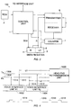
- Fig. 3 is a block diagram schematically showing the construction of an Extended Range Skew Controller 100 of the present invention.
- numeral 1 designates a control unit which handles communication with the other circuitry of the NIU and generates control signals to each of the other components of the Extended Range Skew Controller. Operation of the control unit may be governed by firmware which is stored in a Read Only Memory (ROM) 2 or it may be a state machine as a matter of design choice.
- Skew register 3 is a 12-bit register divided into a low-order 8-bit segment 5 and a high-order 4-bit segment 4.
- the control unit 1 can read data from both segments 4 and 5 of the register.
- the control unit 1 can also write data into high-order segment 4, but it cannot write into low-order segment 5 of the register.
- Counter 7 is an 8-bit counter which can count in a range of 0 to 255.
- Transmitter/receiver circuit 6 is for transmitting and receiving data packets over the network.
- Fig. 4 shows a pair of NIUs 1002 and 1004.
- the upstream frequency band on the broadband cable is shown schematically as a transmission line 1006, with the downstream frequency band being shown as a receiving line 1008. It should be understood however that this is a schematic representation only. In the network being described both upstream and downstream transmissions take place over a single coaxial cable with the upstream portion of the signal being carried on a carrier different from the downstream portion.
- Each of NIUs 1002 and 1004 transmits in the upstream band (line 1006) as shown by arrows 1010, 1012.
- each of NIUs 1002 and 1004 receives signals in a downstream frequency band (line 1008) as shown by arrows 1014, 1016.
- a series of timing marks 1018 which appear in the downstream frequency band are shown beneath line 1008 in Fig. 4.
- NIU 1002 is a distance L1 from HRU 1020
- NIU 1004 is a distance L2 from HRU 1020. If NIU 1002 attempted to transmit in a timeslot defined to begin N microseconds after a timing mark 1018 by actually starting the transmission N microseconds after the timing mark is detected, the transmission would actually be received by NIU 1002 at a time t(skew) later.
- Time t(skew) is (2*L1/C)+t0, where L1 is the distance to HRU 1020, C is the speed of the signal on the transmission medium and t0 is any delay incurred through the HRU.
- a transmission from NIU 1004, on the other hand, will be delayed by (2*L2/C)+t0. Accordingly, data transmitted by NIU 1002 will actually fall farther behind timing mark 1018 than data transmitted by NIU 1004.
- each NIU upon booting up, will determine its particular skew time by transmitting a series of skew signal packets (SSPs) and calculating the amount of time before it correctly receives back an SSP. This time then is designated as a skew time, and each data packet transmitted thereafter will be transmitted an amount of time equal to the skew time earlier than the time that the specified timeslot will be detected on receiving line 1008 at that particular NIU. For example, if a NIU determines a skew time of 38 microseconds, this represents a network of approximately 3 miles in radius (assuming a delay of 6.25 microseconds per mile for an electromagnetic wave in the coaxial medium).
- SSPs skew signal packets
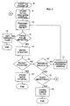
- Fig. 5 is a flowchart illustrating the operation of the Extended Range Skew Controller.
- the control unit initiates skew determination by storing an initial pre-skew interval (9) in high-order part 4 of Skew Register 3.
- the control unit reads this initial pre-skew interval from the NIU.
- the initial pre-skew interval may be set by the user through software controlling the NIU based on the user's estimation of the distance of network node from the head-unit of the network. If no such estimation has been entered by the user, the initial pre-skew interval that the control unit stores in the high-order byte is 0. In an alternative embodiment, no provision is made for the user to set an initial pre-skew interval and the control unit sets an pre-skew interval based on a value stored in ROM 2.
- Transmitting an SSP occurs as follows: After storing the pre-skew interval, the control unit causes transmitter/receiver 6 to transmit an SSP and signals counter 7 to begin counting when the next timing mark is detected. The transmitter/receiver uses the pre-skew value stored in skew register 3 to determine when to send the SSP. The SSP is sent at a time interval before the next timing mark. The resultant time interval, as measured, is the pre-skew value stored in the skew register.
- the transmitter/receiver waits for detection of timing pulse on the reception frequency of the network.
- counter 7 begins counting (12). If a timing pulse is not detected, an error flag is set (13) which can be read by the NIU.
- Counter 7 continues counting for the duration of the SP interval indicated in Fig. 2 or until the packet is received back at the transmitter/receiver after being retransmitted by the HRU (14). If the packet is received at the transmitter/receiver during the signal timing slot, the counter stops counting and stores its value in low-order part 5 of skew register 3 (15).
- control unit 7 stops counting, resets itself (to zero), and signals the control unit that the signal packet was not received.
- the control unit then reads the pre-skew interval stored in high-order segment 4 to determine if the value is 15, which is the largest possible value that the 4-bit segment can hold (16). If the value in part 4 is less than 15, the control unit increments the value in segment 4 by 1 (17), and then signals the transmitter/receiver to transmitter a signal packet with the new pre-skew interval (10). If the value is 15, then the controller waits a pseudo-random amount of time between 20 and 40 seconds and the entire operation is repeated, up to a total of 3 times. At the end of the third repetition, if no SSP has been correctly returned, the controller halts skew determination, removes the node from the network and an error is reported to the NIU (19).
Abstract
Description
- The present invention relates generally to data communications networks and more specifically to an enhancement to network interface units in a high speed data interface network.
- Modern data networks allow for the high speed transmission of digital data between multiple users. Such data might be digitized voice data in a private branch exchange (PBX) office telephone network, video data, or information data from digital information processing systems such as personal computers. Modern networks may allow for the transmissions of all three types of data over the same physical network cable.
- One configuration for such a network is described in International Patent Application PCT/US89/01806, published as WO90/13956. This network is illustrated in Fig. 1, which is a block diagram of a digital data network of the type for which the invention is intended. It is characterized by a
single network medium 12 connected to a plurality of network nodes, represented by Network Interface Units (NIUs) 20 each connected to a phone, computer, or other video, data or voice processing device (P) 22. The single medium is such that it can simultaneously carry a number of different signals, each in a different frequency band, thus allowing the network to have a number of frequency division multiplexed channels for carrying data. Each channel is further divided into two different frequency bands: a transmit frequency band and a receive frequency band. NIUs on the network transmit data on the transmit frequency and receive it on the receive frequency. A single head-end retransmission unit (HRU) 50 receives all data transmitted on the transmit frequency and retransmits it on the receive frequency for reception by all network nodes. - Fig. 2 is a diagram showing the time structure of signals on this network. Circuitry associated with the HRU provides a series of timing mark packets (TMs), transmitted simultaneously on all channels, at 1-ms intervals, thereby defining a series of 1-ms frames.
- In one configuration of the network for which the present invention is designed, each frame consists of a 10-byte TM, a 71-byte (60 data bytes) signalling packet (SP), and 28 19.5-byte (16 data bytes) voice/data timeslots (VTSs), each capable of containing a voice/data packet (VP).
- VPs are used to provide voice communication containing binary encoded (pulse code modulation - PCM) speech from a specific phone conversation or to provide data communication. They are transmitted every cycle during the course of a conversation. When transmitting voice, VPs contain no computer recognizable information. They are merely reconstructed into voice at the receiving node.
- SPs are used for communications between nodes and contain computer recognizable information pertinent to the control of the network. Among the functions of the SPs is the determination of skew intervals.
- Each node is characterized by a skew time related to its physical position on the bus. Skew time refers to the different propagation delays resulting from the fact that the different nodes are at different distances from
HRU 50. The nodes most remote from the HRU will receive the timing marks latest in time, and would, if they merely synchronized their transmissions to the timing mark, transmit relatively late compared to nodes nearer the HRU. - As a result of this skew time, there is a limit to the geographic range of the network. A typical maximum range in the prior art is about 5 km.
- According to the invention, apparatus and method are provided for correcting for the different propagation delays in a bidirectional digital data network, thereby allowing a network of the type described to operate at a range of up to 80 km. The present invention is directed to a method and means whereupon each node determines its own skew time relative to other nodes. Each node, on power-up, transmits a series of signalling packets (SPs) upon receiving a timing mark and counts the number of clock cycles up to the width of the SP time period (1/(5.018 MHz)) until it receives the same SP (as retransmitted by the HRU). The first SP is transmitted at a pre-set pre-skew interval before the timing mark. If the SP is not received within the SP time period, the node increases the pre-skew interval and transmits a new SP. Once an SP is correctly received back at the node, the timing delay between transmission and reception is retained. This defines twice that node's skew time, and subsequent transmissions will be advanced by the skew time.
- The invention will be understood upon reference to the following detailed description in connection with the remaining accompanying drawings, which are described by way of example, and in which:
- Fig. 3 is a schematic block diagram of an enhanced skew controller according to the invention;
- Fig. 4 is a schematic diagram illustrating the transmission time differences to the head-end retransmission unit;
- Fig. 5 is a flow chart showing the determination of skew time.
- Fig. 3 is a block diagram schematically showing the construction of an Extended
Range Skew Controller 100 of the present invention. In the figure,numeral 1 designates a control unit which handles communication with the other circuitry of the NIU and generates control signals to each of the other components of the Extended Range Skew Controller. Operation of the control unit may be governed by firmware which is stored in a Read Only Memory (ROM) 2 or it may be a state machine as a matter of design choice.Skew register 3 is a 12-bit register divided into a low-order 8-bit segment 5 and a high-order 4-bit segment 4. Thecontrol unit 1 can read data from bothsegments 4 and 5 of the register. Thecontrol unit 1 can also write data into high-order segment 4, but it cannot write into low-order segment 5 of the register.Counter 7 is an 8-bit counter which can count in a range of 0 to 255. Transmitter/receiver circuit 6 is for transmitting and receiving data packets over the network. - Fig. 4 shows a pair of NIUs 1002 and 1004. The upstream frequency band on the broadband cable is shown schematically as a
transmission line 1006, with the downstream frequency band being shown as areceiving line 1008. It should be understood however that this is a schematic representation only. In the network being described both upstream and downstream transmissions take place over a single coaxial cable with the upstream portion of the signal being carried on a carrier different from the downstream portion. Each of NIUs 1002 and 1004 transmits in the upstream band (line 1006) as shown byarrows arrows timing marks 1018 which appear in the downstream frequency band are shown beneathline 1008 in Fig. 4. - As can be seen, NIU 1002 is a distance L1 from HRU 1020, while NIU 1004 is a distance L2 from
HRU 1020. If NIU 1002 attempted to transmit in a timeslot defined to begin N microseconds after atiming mark 1018 by actually starting the transmission N microseconds after the timing mark is detected, the transmission would actually be received by NIU 1002 at a time t(skew) later. Time t(skew) is (2*L₁/C)+t₀, where L₁ is the distance toHRU 1020, C is the speed of the signal on the transmission medium and t₀ is any delay incurred through the HRU. A transmission from NIU 1004, on the other hand, will be delayed by (2*L2/C)+t₀. Accordingly, data transmitted by NIU 1002 will actually fall farther behindtiming mark 1018 than data transmitted by NIU 1004. - According to the present invention, each NIU, upon booting up, will determine its particular skew time by transmitting a series of skew signal packets (SSPs) and calculating the amount of time before it correctly receives back an SSP. This time then is designated as a skew time, and each data packet transmitted thereafter will be transmitted an amount of time equal to the skew time earlier than the time that the specified timeslot will be detected on receiving
line 1008 at that particular NIU. For example, if a NIU determines a skew time of 38 microseconds, this represents a network of approximately 3 miles in radius (assuming a delay of 6.25 microseconds per mile for an electromagnetic wave in the coaxial medium). - Fig. 5 is a flowchart illustrating the operation of the Extended Range Skew Controller. When a NIU begins operation on the network, either after a reset or on power-up (8), the control unit initiates skew determination by storing an initial pre-skew interval (9) in high-order part 4 of Skew
Register 3. The control unit reads this initial pre-skew interval from the NIU. The initial pre-skew interval may be set by the user through software controlling the NIU based on the user's estimation of the distance of network node from the head-unit of the network. If no such estimation has been entered by the user, the initial pre-skew interval that the control unit stores in the high-order byte is 0. In an alternative embodiment, no provision is made for the user to set an initial pre-skew interval and the control unit sets an pre-skew interval based on a value stored inROM 2. - Transmitting an SSP (10) occurs as follows: After storing the pre-skew interval, the control unit causes transmitter/
receiver 6 to transmit an SSP and signals counter 7 to begin counting when the next timing mark is detected. The transmitter/receiver uses the pre-skew value stored inskew register 3 to determine when to send the SSP. The SSP is sent at a time interval before the next timing mark. The resultant time interval, as measured, is the pre-skew value stored in the skew register. - Once the SSP is transmitted, the transmitter/receiver waits for detection of timing pulse on the reception frequency of the network. When a timing pulse is detected (11)
counter 7 begins counting (12). If a timing pulse is not detected, an error flag is set (13) which can be read by the NIU. -
Counter 7 continues counting for the duration of the SP interval indicated in Fig. 2 or until the packet is received back at the transmitter/receiver after being retransmitted by the HRU (14). If the packet is received at the transmitter/receiver during the signal timing slot, the counter stops counting and stores its value in low-order part 5 of skew register 3 (15). - If the packet is not received before the end of the signal timing slot,
counter 7 stops counting, resets itself (to zero), and signals the control unit that the signal packet was not received. The control unit then reads the pre-skew interval stored in high-order segment 4 to determine if the value is 15, which is the largest possible value that the 4-bit segment can hold (16). If the value in part 4 is less than 15, the control unit increments the value in segment 4 by 1 (17), and then signals the transmitter/receiver to transmitter a signal packet with the new pre-skew interval (10). If the value is 15, then the controller waits a pseudo-random amount of time between 20 and 40 seconds and the entire operation is repeated, up to a total of 3 times. At the end of the third repetition, if no SSP has been correctly returned, the controller halts skew determination, removes the node from the network and an error is reported to the NIU (19). - All publications and other references or patent documents cited herein are incorporated by reference. It is to be understood that the above description is intended to be illustrative and not restrictive. Many embodiments will be apparent to those skilled in the art upon reviewing the above description. The scope of the invention, therefore, should be determined with reference to the appended claims, along with the full scope of equivalents to which such claims are entitled.
Claims (5)
- A method for determining skew interval in a long range digital network comprising the steps of:
transmitting a signalling packet at a user-set pre-skew interval prior to a timing pulse;
counting the number of clock cycles after the timing pulse until the signalling packet is returned; and
storing the sum of said counted clock cycles and said user-set pre-skew interval as the skew interval. - A method for determining the skew interval in a long range digital network comprising the steps of:a) transmitting a signalling packet at a pre-skew interval prior to a timing clock; thereafterb) counting the number of clock cycles after the timing clock until the signalling packet is returned;c) if the packet is not returned within a predefined time period, increasing the pre-skew interval and then repeating steps a) and b) until the packet is returned during the predefined time period; andupon the packet being returned during the predefined time period, storing the resultant sum of said counted value and said pre-skew interval as the skew interval.
- An apparatus in a network interface unit for determining the skew interval in a long range digital network comprising:
means for storing a pre-skew interval based on geographical distance of said network interface unit from a headend unit of said digital network;
means coupled to said storing means for transmitting a signalling packet at said pre-skew interval prior to a timing clock signal;
receiving means for receiving said signalling packet;
counting means coupled to said receiving means for counting clock cycles following the timing clock signal until the signalling packet is returned;
controller means coupled to said counting means and said storing means for detecting if said counting means has detected a received packet prior to elapse of a preset time period and, if said preset time period has not elapsed, for iteratively increasing the pre-skew interval and directing said transmitting means to retransmit the signalling packet until the counting means detects a received signalling packet within said predefined time period; and
storage means for storing the counter value indicative of the time a packet is returned during the predefined time period. - The apparatus according to claim 3 where said pre-skew interval is set by a user.
- A circuit in a network interface unit for determining the skew interval in a long range digital network employing a central clock and central timing pulse signal comprising:
a skew register having a low-order part and a high-order part;
a network transmitter means coupled to said skew register for transmitting signal packets and data packets at a transmit time which is stored in said skew register, said transmit time being prior to said timing pulse;
a network receiver for receiving packets;
a counter coupled to said bus receiver and said skew register for counting the number of clock cycles which elapse between occurrence of timing pulse detection and receipt of a signalling packet by the network receiver and for storing said interval in said low-order part of said skew register; and
a controller coupled to said high-order part of said skew register, said transmitter and said counter for detecting when said counter has failed to detect a received packet in a predetermined time from said timing pulse, for increasing an interval stored in said high-order part of said skew register and for directing said transmitter to retransmit said signal packet at an increased pre-skew interval.
Applications Claiming Priority (2)
| Application Number | Priority Date | Filing Date | Title |
|---|---|---|---|
| US53994 | 1993-04-27 | ||
| US08/053,994 US5408507A (en) | 1993-04-27 | 1993-04-27 | Extended range enhanced skew controller |
Publications (2)
| Publication Number | Publication Date |
|---|---|
| EP0622926A2 true EP0622926A2 (en) | 1994-11-02 |
| EP0622926A3 EP0622926A3 (en) | 1996-03-27 |
Family
ID=21987993
Family Applications (1)
| Application Number | Title | Priority Date | Filing Date |
|---|---|---|---|
| EP94302990A Withdrawn EP0622926A3 (en) | 1993-04-27 | 1994-04-26 | Extended range enhanced skew controller. |
Country Status (4)
| Country | Link |
|---|---|
| US (1) | US5408507A (en) |
| EP (1) | EP0622926A3 (en) |
| CN (1) | CN1086089C (en) |
| PH (1) | PH31186A (en) |
Cited By (19)
| Publication number | Priority date | Publication date | Assignee | Title |
|---|---|---|---|---|
| WO1996017452A1 (en) * | 1994-11-30 | 1996-06-06 | Alcatel N.V. | Burst alignment procedure |
| EP0928077A2 (en) * | 1997-12-30 | 1999-07-07 | Alcatel | Method for increasing the range of a radiocommunications unit and unit for carrying out the method |
| WO2004023729A1 (en) * | 2002-09-04 | 2004-03-18 | Tiaris, Inc. | A home network device |
| US7697522B2 (en) | 2006-11-20 | 2010-04-13 | Broadcom Corporation | Systems and methods for aggregation of packets for transmission through a communications network |
| US7742495B2 (en) | 2006-11-20 | 2010-06-22 | Broadcom Corporation | System and method for retransmitting packets over a network of communication channels |
| US7782850B2 (en) | 2006-11-20 | 2010-08-24 | Broadcom Corporation | MAC to PHY interface apparatus and methods for transmission of packets through a communications network |
| US8090043B2 (en) | 2006-11-20 | 2012-01-03 | Broadcom Corporation | Apparatus and methods for compensating for signal imbalance in a receiver |
| US8098770B2 (en) | 2008-05-06 | 2012-01-17 | Broadcom Corporation | Unbiased signal-to-noise ratio estimation for receiver having channel estimation error |
| US8174999B2 (en) | 2000-08-30 | 2012-05-08 | Broadcom Corporation | Home network system and method |
| US8238227B2 (en) | 2008-12-22 | 2012-08-07 | Broadcom Corporation | Systems and methods for providing a MoCA improved performance for short burst packets |
| US8254413B2 (en) | 2008-12-22 | 2012-08-28 | Broadcom Corporation | Systems and methods for physical layer (“PHY”) concatenation in a multimedia over coax alliance network |
| US8611327B2 (en) | 2010-02-22 | 2013-12-17 | Broadcom Corporation | Method and apparatus for policing a QoS flow in a MoCA 2.0 network |
| US8737254B2 (en) | 2008-12-22 | 2014-05-27 | Broadcom Corporation | Systems and methods for reducing reservation request overhead in a communications network |
| US8953594B2 (en) | 2010-02-23 | 2015-02-10 | Broadcom Corporation | Systems and methods for increasing preambles |
| US9184984B2 (en) | 2000-08-30 | 2015-11-10 | Broadcom Corporation | Network module |
| US9531619B2 (en) | 2009-04-07 | 2016-12-27 | Broadcom Corporation | Channel assessment in an information network |
| US9554177B2 (en) | 2009-03-30 | 2017-01-24 | Broadcom Corporation | Systems and methods for retransmitting packets over a network of communication channels |
| US9641456B2 (en) | 2007-05-31 | 2017-05-02 | Avago Technologies General Ip (Singapore) Pte. Ltd. | Apparatus and methods for reduction of transmission delay in a communication network |
| US9807692B2 (en) | 2008-07-31 | 2017-10-31 | Avago Technologies General Ip (Singapore) Pte. Ltd. | Systems and methods for providing power management |
Families Citing this family (9)
| Publication number | Priority date | Publication date | Assignee | Title |
|---|---|---|---|---|
| JP3000911B2 (en) * | 1996-01-10 | 2000-01-17 | 日本電気株式会社 | Automatic setting of optimal number of frames waiting for retransmission of automatic retransmission protocol in mobile facsimile communication |
| US5870554A (en) * | 1996-04-01 | 1999-02-09 | Advanced Micro Devices, Inc. | Server selection method where a client selects a server according to address, operating system and found frame for remote booting |
| US5960175A (en) * | 1996-04-01 | 1999-09-28 | Advanced Micro Devices, Inc. | Identification and selection of a desired server from a plurality of servers of varying protocols on the same network via a single boot ROM |
| US5719862A (en) * | 1996-05-14 | 1998-02-17 | Pericom Semiconductor Corp. | Packet-based dynamic de-skewing for network switch with local or central clock |
| US6466626B1 (en) | 1999-02-23 | 2002-10-15 | International Business Machines Corporation | Driver with in-situ variable compensation for cable attenuation |
| US20070169152A1 (en) * | 2005-12-30 | 2007-07-19 | Daniel Roodnick | Data and wireless frame alignment for error reduction |
| US8730798B2 (en) | 2009-05-05 | 2014-05-20 | Broadcom Corporation | Transmitter channel throughput in an information network |
| US8867355B2 (en) | 2009-07-14 | 2014-10-21 | Broadcom Corporation | MoCA multicast handling |
| US8942250B2 (en) | 2009-10-07 | 2015-01-27 | Broadcom Corporation | Systems and methods for providing service (“SRV”) node selection |
Citations (1)
| Publication number | Priority date | Publication date | Assignee | Title |
|---|---|---|---|---|
| EP0334569A2 (en) * | 1988-03-21 | 1989-09-27 | First Pacific Networks, Inc. | Method of and system for transmitting information |
Family Cites Families (3)
| Publication number | Priority date | Publication date | Assignee | Title |
|---|---|---|---|---|
| US4411007A (en) * | 1981-04-29 | 1983-10-18 | The Manitoba Telephone System | Distributed network synchronization system |
| US4926446A (en) * | 1988-11-25 | 1990-05-15 | Alberta Telecommunications Research Centre | Method and apparatus for precision time distribution in telecommunication networks |
| US5095444A (en) * | 1989-12-21 | 1992-03-10 | Legent Corporation | System and method for measuring inter-nodal transmission delays in a communications network |
-
1993
- 1993-04-27 US US08/053,994 patent/US5408507A/en not_active Expired - Fee Related
-
1994
- 1994-04-25 PH PH48146A patent/PH31186A/en unknown
- 1994-04-26 EP EP94302990A patent/EP0622926A3/en not_active Withdrawn
- 1994-04-26 CN CN94104869A patent/CN1086089C/en not_active Expired - Fee Related
Patent Citations (1)
| Publication number | Priority date | Publication date | Assignee | Title |
|---|---|---|---|---|
| EP0334569A2 (en) * | 1988-03-21 | 1989-09-27 | First Pacific Networks, Inc. | Method of and system for transmitting information |
Cited By (31)
| Publication number | Priority date | Publication date | Assignee | Title |
|---|---|---|---|---|
| ES2103190A1 (en) * | 1994-11-30 | 1997-08-16 | Alcatel Standard Electrica | Burst alignment procedure |
| AU691380B2 (en) * | 1994-11-30 | 1998-05-14 | Alcatel N.V. | Burst alignment procedure |
| WO1996017452A1 (en) * | 1994-11-30 | 1996-06-06 | Alcatel N.V. | Burst alignment procedure |
| EP0928077A2 (en) * | 1997-12-30 | 1999-07-07 | Alcatel | Method for increasing the range of a radiocommunications unit and unit for carrying out the method |
| EP0928077A3 (en) * | 1997-12-30 | 2003-07-30 | Alcatel | Method for increasing the range of a radiocommunications unit and unit for carrying out the method |
| US8174999B2 (en) | 2000-08-30 | 2012-05-08 | Broadcom Corporation | Home network system and method |
| US9184984B2 (en) | 2000-08-30 | 2015-11-10 | Broadcom Corporation | Network module |
| US9160555B2 (en) | 2000-08-30 | 2015-10-13 | Broadcom Corporation | Home network system and method |
| US9094226B2 (en) | 2000-08-30 | 2015-07-28 | Broadcom Corporation | Home network system and method |
| US8761200B2 (en) | 2000-08-30 | 2014-06-24 | Broadcom Corporation | Home network system and method |
| WO2004023729A1 (en) * | 2002-09-04 | 2004-03-18 | Tiaris, Inc. | A home network device |
| US8358663B2 (en) | 2006-11-20 | 2013-01-22 | Broadcom Corporation | System and method for retransmitting packets over a network of communication channels |
| US7782850B2 (en) | 2006-11-20 | 2010-08-24 | Broadcom Corporation | MAC to PHY interface apparatus and methods for transmission of packets through a communications network |
| US7697522B2 (en) | 2006-11-20 | 2010-04-13 | Broadcom Corporation | Systems and methods for aggregation of packets for transmission through a communications network |
| US7742495B2 (en) | 2006-11-20 | 2010-06-22 | Broadcom Corporation | System and method for retransmitting packets over a network of communication channels |
| US9008086B2 (en) | 2006-11-20 | 2015-04-14 | Broadcom Corporation | MAC to PHY interface apparatus and methods for transmission of packets through a communications network |
| US8831028B2 (en) | 2006-11-20 | 2014-09-09 | Broadcom Corporation | System and method for retransmitting packets over a network of communication channels |
| US8090043B2 (en) | 2006-11-20 | 2012-01-03 | Broadcom Corporation | Apparatus and methods for compensating for signal imbalance in a receiver |
| US9641456B2 (en) | 2007-05-31 | 2017-05-02 | Avago Technologies General Ip (Singapore) Pte. Ltd. | Apparatus and methods for reduction of transmission delay in a communication network |
| US8098770B2 (en) | 2008-05-06 | 2012-01-17 | Broadcom Corporation | Unbiased signal-to-noise ratio estimation for receiver having channel estimation error |
| US9807692B2 (en) | 2008-07-31 | 2017-10-31 | Avago Technologies General Ip (Singapore) Pte. Ltd. | Systems and methods for providing power management |
| US8804480B2 (en) | 2008-12-22 | 2014-08-12 | Broadcom Corporation | Systems and methods for providing a MoCA improved performance for short burst packets |
| US8811403B2 (en) | 2008-12-22 | 2014-08-19 | Broadcom Corporation | Systems and methods for physical layer (“PHY”) concatenation in a multimedia over coax alliance network |
| US8737254B2 (en) | 2008-12-22 | 2014-05-27 | Broadcom Corporation | Systems and methods for reducing reservation request overhead in a communications network |
| US8238227B2 (en) | 2008-12-22 | 2012-08-07 | Broadcom Corporation | Systems and methods for providing a MoCA improved performance for short burst packets |
| US8254413B2 (en) | 2008-12-22 | 2012-08-28 | Broadcom Corporation | Systems and methods for physical layer (“PHY”) concatenation in a multimedia over coax alliance network |
| US9554177B2 (en) | 2009-03-30 | 2017-01-24 | Broadcom Corporation | Systems and methods for retransmitting packets over a network of communication channels |
| US9531619B2 (en) | 2009-04-07 | 2016-12-27 | Broadcom Corporation | Channel assessment in an information network |
| US8611327B2 (en) | 2010-02-22 | 2013-12-17 | Broadcom Corporation | Method and apparatus for policing a QoS flow in a MoCA 2.0 network |
| US8942220B2 (en) | 2010-02-22 | 2015-01-27 | Broadcom Corporation | Method and apparatus for policing a flow in a network |
| US8953594B2 (en) | 2010-02-23 | 2015-02-10 | Broadcom Corporation | Systems and methods for increasing preambles |
Also Published As
| Publication number | Publication date |
|---|---|
| CN1102025A (en) | 1995-04-26 |
| US5408507A (en) | 1995-04-18 |
| EP0622926A3 (en) | 1996-03-27 |
| CN1086089C (en) | 2002-06-05 |
| PH31186A (en) | 1998-04-24 |
Similar Documents
| Publication | Publication Date | Title |
|---|---|---|
| US5408507A (en) | Extended range enhanced skew controller | |
| US4536875A (en) | Retransmission control system | |
| US4506361A (en) | Retransmission control system | |
| US8005072B2 (en) | Synchronization of multiple base stations in a wireless communication system | |
| JP2821715B2 (en) | Method and apparatus for transmission path delay measurement using adaptive demodulation | |
| US5710765A (en) | Method and apparatus for increasing the system efficiency of a TDMA system by reducing time slot guard time | |
| CA2185831C (en) | Method and apparatus for supporting tdma operation over hybrid fiber coaxial (hfc) or other channels | |
| US4757460A (en) | Communications network with individualized access delays | |
| WO1995001022A1 (en) | Arrangement for defining a transmission delay in a subscriber network | |
| CN102932278A (en) | Estimating wireless processing device queue length and estimating signal reception quality in a wireless network | |
| WO1997015129A1 (en) | Method and apparatus for network access control with implicit ranging and dynamically assigned time slots | |
| EP1161805B1 (en) | Synchronization of voice packet generation to unsolicited grants in a docsis cable modem voice over packet telephone | |
| US4797878A (en) | Multiple virtual multipoint modem using TDM/token throwing technique | |
| US4573045A (en) | Collision detection method using CRC code | |
| JPS63100838A (en) | Method and apparatus for ensuring bit synchronization of data block | |
| JPH0666795B2 (en) | Data transmission with improved message format | |
| JP2002026941A (en) | Wireless network provided with capability measurement device | |
| US4432090A (en) | Automatic error correction system for teleprinter traffic with bunched repetition | |
| US5808766A (en) | Method for measuring a signal transmission delay time, central station, terminal station and network to perform this method | |
| JPH0738631B2 (en) | Frame synchronization establishment method | |
| EP0334569B1 (en) | Method of and system for transmitting information | |
| CA1288835C (en) | Line delay compensation for digital transmission systems utilizing low power line drivers | |
| EA005608B1 (en) | Synchronisation method for the uplink channel in a point-to-multipoint communication with ofdm modulation | |
| HU220211B (en) | Burst aligment procedure and cordless terminal | |
| CA2575724A1 (en) | Master electronics card with adaptive bandwidth circuit |
Legal Events
| Date | Code | Title | Description |
|---|---|---|---|
| PUAI | Public reference made under article 153(3) epc to a published international application that has entered the european phase |
Free format text: ORIGINAL CODE: 0009012 |
|
| AK | Designated contracting states |
Kind code of ref document: A2 Designated state(s): AT BE CH DE DK ES FR GB GR IE IT LI LU MC NL PT SE |
|
| RAX | Requested extension states of the european patent have changed |
Free format text: SI |
|
| 17P | Request for examination filed |
Effective date: 19950425 |
|
| PUAL | Search report despatched |
Free format text: ORIGINAL CODE: 0009013 |
|
| AK | Designated contracting states |
Kind code of ref document: A3 Designated state(s): AT BE CH DE DK ES FR GB GR IE IT LI LU MC NL PT SE |
|
| 17Q | First examination report despatched |
Effective date: 20021121 |
|
| RTI1 | Title (correction) |
Free format text: EXTENDED RANGE ENHANCED SKEW CONTROLLING METHOD AND CONTROLLER |
|
| GRAP | Despatch of communication of intention to grant a patent |
Free format text: ORIGINAL CODE: EPIDOSNIGR1 |
|
| STAA | Information on the status of an ep patent application or granted ep patent |
Free format text: STATUS: THE APPLICATION IS DEEMED TO BE WITHDRAWN |
|
| 18D | Application deemed to be withdrawn |
Effective date: 20031101 |