EP0625331B1 - Combined steam and vacuum cleaner - Google Patents
Combined steam and vacuum cleaner Download PDFInfo
- Publication number
- EP0625331B1 EP0625331B1 EP94303595A EP94303595A EP0625331B1 EP 0625331 B1 EP0625331 B1 EP 0625331B1 EP 94303595 A EP94303595 A EP 94303595A EP 94303595 A EP94303595 A EP 94303595A EP 0625331 B1 EP0625331 B1 EP 0625331B1
- Authority
- EP
- European Patent Office
- Prior art keywords
- steam
- vacuum cleaner
- water
- cleaning fluid
- cleaner according
- Prior art date
- Legal status (The legal status is an assumption and is not a legal conclusion. Google has not performed a legal analysis and makes no representation as to the accuracy of the status listed.)
- Expired - Lifetime
Links
Images


Classifications
-
- A—HUMAN NECESSITIES
- A47—FURNITURE; DOMESTIC ARTICLES OR APPLIANCES; COFFEE MILLS; SPICE MILLS; SUCTION CLEANERS IN GENERAL
- A47L—DOMESTIC WASHING OR CLEANING; SUCTION CLEANERS IN GENERAL
- A47L11/00—Machines for cleaning floors, carpets, furniture, walls, or wall coverings
- A47L11/40—Parts or details of machines not provided for in groups A47L11/02 - A47L11/38, or not restricted to one of these groups, e.g. handles, arrangements of switches, skirts, buffers, levers
- A47L11/4036—Parts or details of the surface treating tools
- A47L11/4041—Roll shaped surface treating tools
-
- A—HUMAN NECESSITIES
- A47—FURNITURE; DOMESTIC ARTICLES OR APPLIANCES; COFFEE MILLS; SPICE MILLS; SUCTION CLEANERS IN GENERAL
- A47L—DOMESTIC WASHING OR CLEANING; SUCTION CLEANERS IN GENERAL
- A47L11/00—Machines for cleaning floors, carpets, furniture, walls, or wall coverings
- A47L11/34—Machines for treating carpets in position by liquid, foam, or vapour, e.g. by steam
-
- A—HUMAN NECESSITIES
- A47—FURNITURE; DOMESTIC ARTICLES OR APPLIANCES; COFFEE MILLS; SPICE MILLS; SUCTION CLEANERS IN GENERAL
- A47L—DOMESTIC WASHING OR CLEANING; SUCTION CLEANERS IN GENERAL
- A47L11/00—Machines for cleaning floors, carpets, furniture, walls, or wall coverings
- A47L11/40—Parts or details of machines not provided for in groups A47L11/02 - A47L11/38, or not restricted to one of these groups, e.g. handles, arrangements of switches, skirts, buffers, levers
- A47L11/408—Means for supplying cleaning or surface treating agents
- A47L11/4086—Arrangements for steam generation
Definitions
- the present invention relates to a vacuum cleaner having means for vaporizing cleaning fluid.
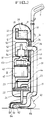
- a conventional up-right electric vacuum cleaner as illustrated in Figure 1, comprises: a fan motor 2 disposed on a lower side of the body 1 for generating suction force according to operation of the cleaner 1; a dust collecting pouch 4 disposed on an upper side of the fan motor 2 for collecting dust sucked in through a suction hose 3; a brush 5 disposed on the lower side of the body of the cleaner 1 for being rotated according to operation of the fan motor 2; and a suction head 6 disposed on the lower side of the body of the cleaner 1 for sucking dust into a suction port 6a to dispatch the same to the suction hose 3.
- a cover 7 is fitted to a front of the body 1 of the cleaner, so that the same can be opened and closed for change of the dust collecting pouch 4, and a plurality of exhaust holes 8 are formed on a lower side of the cover 7 in order to discharge sucked air to an outside of the body 1.
- the dust, waste or the like can be collected by the conventional technique to a degree.
- stains absorbed into a floor, old stains or the like cannot be removed, decreasing the cleaning effectiveness markedly and causing inconvenience to users by requiring separate wiping with a damp cloth or the like.
- the above-identified cleaner can achieve the effect of wet-mop cleaning to a degree but it is difficult to remove stains absorbed into the floor or old stains. Besides, there is a problem in that the cleaning effectiveness is reduced due to excess water delivery thereby leaving behind stains after the cleaning. Furthermore, the excess water is unhygienic and can lead to the spread of harmful germs.
- DE-U-9216531 discloses a vacuum cleaner including driving means for generation a suction force, a source of cleaning fluid and delivery means for delivering cleaning fluid from said source to a floor to be cleaned, including a heater for vaporizing the cleaning fluid before delivery to said floor.
- US-A-4353145 discloses a vacuum cleaner including a source of cleaning fluid, delivery means for delivering cleaning fluid from said source to a floor to be cleaned.
- the disclosed cleaner requires the fluid to be preheated.
- a vacuum cleaner including driving means for generation a suction force, a source of cleaning fluid, mopping means for removing liquid from said floor, a heater for vaporizing the cleaning fluid delivery means, for delivering cleaning fluid from said source to a floor to be cleaned or the mopping means, wherein the delivery means includes a conduit conveying exhaust from the driving means to the heater and an atomizing means for atomizing said cleaning fluid and ejecting it into said conduit.
- Figure 2 is a sectional view for illustrating an electric vacuum cleaner according to the first embodiment of the present invention, where reference numeral 10 represents a body of the cleaner having a handle 11 coupled to one side thereof and a cover 12 detachably coupled to a front thereof.
- the body 10 is coupled thereunder with a steam generating means 20 for generating steam according to operation of the cleaner, and is coupled thereupon with a water supply means 30 for supplying water W into the steam generating means 20.
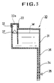
- the water supply means 30, as illustrated in Figure 3, is disposed with a water storage 31 for storing a predetermined quantity of water W therein, upon which there is formed a water filling port 32 for water refilling.
- the water filling port 32 is screwed at an approximate central area thereof to a lid 33 formed with an orifice 33a for air circulation.
- a water pipe 36 is connected at a lower side of the water storage 31 to a check valve 34 for prevention of water W counterflow and to a flow control valve 35 for controlling discharge quantity of water W that is supplied.
- a floater 37 is disposed within the water storage 31 in order to prevent the water W from overflowing according to the quantity of the water W.
- a dust collecting means 50 is disposed under the water supply means 30, which collects the dust and the like sucked in by suction force generated by activation of a driving means 40.
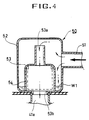
- the dust collecting means separates the dust and the waste water sucked in by the suction head 60 connected to the lower side of the body 10 and by a suction pipe 51 connected there between to thereafter store the same separately.
- the waste water W1 sucked in from the suction pipe 51 can be stored in a waster water storage tank 52, detachably connected to an upper side of the driving means 40 because filter box 53 is integrally formed therewith.
- the filter box 53 is formed thereon with a suction port 5a for sucking in the air and the dust infused into the waste water storage tank 52.
- the filter box 53 is detachably disposed therein with a filter 54 for storing the sucked-in dust and the filter box is formed thereunder with a discharge port 53b for discharging the air which has passed the filter 54.
- the filter should be formed with a mesh pouch, through which the air can pass but the dust cannot pass.
- the mesh pouch is filled with the dust, the dust can be taken out through the discharge port 53b formed under the filter box 53.
- the driving means 40 disposed under the dust collecting means 50 is housed in a housing 41 connected to the waste water storage tank 52 and is rotatively disposed with an impellor 43 for generating suction force by being rotated according to the activation of a driving motor 42 installed under the housing 41.
- a suction port 41a connected to the discharge port 5b is formed on an upper side of the housing 41 for air circulation and at the same time, an exhaust port 41b is formed at one side thereof in order to discharge part of the purified air sucked in from the suction port 41a.
- a discharge pipe 44 is connected to the other side of the housing 41 in order to supply the purified air into the steam generating means 20.
- An exhaust valve 45 is disposed in the discharge pipe 44 in order to discharge the purified air within the housing 41 according to the opening and closing operation.
- a pressure sensor 46 is disposed above the valve 45 in order to control an opening degree of the exhaust valve according to pressure within the housing 41.
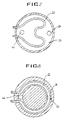
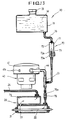
- the steam generating means 20 disposed under the driving means 40 for generating steam by being supplied of the water W from the water supply means 30, as illustrated in Figures 6 and 7, is disposed with a heater 22 in a steam chamber 21 for generating heat according to supply of the electric source, and an exhaust pipe 44 is connected to one side thereof in order to enable the purified air to be infused.
- the exhaust pipe 44 connected at one side thereof to a water supply pipe 36 is formed with an ejection nozzle 23 of a small diameter for ejecting water W discharged by pressure of the purified air in an atomization state.
- a steam exhaust pipe 24 is connected to the other side of the steam chamber 221 in order to discharge the air changed into the atomization state according to the activation of the heater 22 toward the suction head 60.
- the water W in the ejection nozzle 3 supplied through the supply pipe 36 is ejected into the steam chamber 21 in the atomization state by the pressure of the air discharged from the exhaust pipe 44 to thereby shorten heating time and facilitate the steam to be generated easily as well.
- shapes of the steam chamber 21 and the heater 22 are not limited to the present embodiment.
- the steam chamber 21 can be made in a ring shape with the same shape of heater 22 installed therein to thereby improve heat efficiency of the heater 22 and further facilitate the generation of the steam.
- the steam generating means 20 is not limited to the present embodiment, and by way of example, as illustrated in Figure 9, the water supply pipe 36 can be disposed with an ultrasonic wave humidifying means 25 having a trembler 25a to thereby atomize the water W supply the same along with the purified air into the steam chamber 21.
- the water supply pipe 36 and the exhaust pipe 44 are connected to the steam chamber 21 respectively, and according to the closing and opening of respective valves 26a and 26b installed within the exhaust pipe 44 and steam exhaust pipe 24, the steam generated from the steam chamber 21 can be discharged into the steam exhaust pipe 24.
- the steam within the steam chamber 21 cannot realize infuse of the air from the steam exhaust pipe 24 when the valves 26a and 26b are closed to thereby curve the discharge of the steam, and when the valves 26a and 26b are opened, the steam is discharged into the suction head 60 through the steam exhaust pipe 24 by pressure of the air discharged from the exhaust pipe 24 according to the activation of the driving means 40.
- valves 26a and 26b are systematically operated with a flow control valve 35 disposed a the water supply pipe 36 in the water supply means 30, thereby enabling discharged quantity of the water, air and the steam to be controlled.
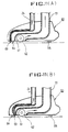
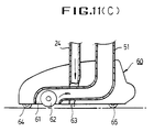
- the suction head 60 installed under the body 10 of the cleaner, as illustrated in Figure 11, is disposed with the suction pipe 51 connected to the dust collecting means 50 at the other end thereof, and one end of which is formed with a suction prot 61 facing the floor in order to absorb the dust, foreign objects and the waste water.
- a revolving cloth 62 is rotatively disposed in order to enable a wet cloth cleaning.
- a steam ejection port 63 for ejecting steam generated from the steam generating means 20 is connectedly formed with the steam exhaust pipe 24.
- Contrivance of the steam ejection port 63 facing the floor at a front of the suction port 61 is not limited to the present invention, and, by way of example, as illustrated in Figure 11b, the steam ejection prot 63 can be positioned to face the suction port 61 to thereby eject the steam directly to a periphery of the revolving cloth 62, or the same can be positioned at a rear of the suction port 61 as illustrated in Figure 11c.
- Unexplained reference numerals 64 and 65 in the drawing represent a front wheel and rear wheel rotatively connected to the lower side of the suction head 60.
- the water W stored in the storage 31 of the water supply means 30 is dispatched to the steam chamber 21 through the water supply pipe 44.
- the water W is then atomized at the ejection nozzle 23 by pressure supplied according to the suction force of the impellor 43 to thereby be sent to the steam chamber 21.
- the exhaust pipe 44 and water supply pipe 36 are joined at the ejection nozzle 23.
- the check valve 34 prevents the water W from flowing backward.
- the lid 33 is screwed to the upper side of the storage 31, the water W can be refilled.
- the lid 33 is formed with an orifice 33a for air circulation, so that pressure of the water W discharged through water supply pipe 36 can maintained at a predetermined level.
- the floater 37 disposed therein prevents the water W in the storage 31 from overflowing or undulating.
- the atomized water W dispatched to the steam chamber 21 is therefore heated by the heater 22 and is ejected to the steam ejection port 63 formed at the suction head 60 through the steam exhaust pipe 24.
- the steam ejected into the steam ejection port 63 is now ejected to the to-be-cleaned floor in a high temperature state to thereby perform sterilization and at the same time, to make it possible to perform separate cleaning of the stains, old dirts and the like by way of operation of the revolving wet cloth 62.
- the collected waste water W1 is sucked into the waste water storage tank 52 along with the dust.
- the cloth 62 when the steam is supplied to the periphery of the cloth 62 though the steam ejection port 63, the cloth 62 is rotatively operated to and fro to thereby perform the wet cloth cleaning, and at the same time, the foreign objects smeared into the floor can be removed to thereafter be sucked into the suction port 61 along with the dust and waste water.
- the waste water W1 sucked into the waste water storage tank 52 is dropped to an inner floor thereof to thereby be stored, and the air inclusive of the dust is sucked into the tank through a filer entrance 53a formed at an upper side of the filter box 53.
- the purified air which has passed the filter 54 is sucked into the housing 41 though a filter exit 53b by pressure according to the operation of the impellor 42.
- Part of the air sucked into the housing 41 is discharged to an outside of the body 10 of the cleaner through the exhaust port 41b formed at one side thereof and balance of the air is discharged to the steam generating means 20 through the exhaust pipe 44.
- the steam generated by the steam generating means 20 is ejected through the steam ejection port 63 formed under the suction head 60, the steam is ejected to the periphery of the revolving wet cloth 62, to thereby enable the wet cloth cleaning.
- Quantity of steam discharged through the steam ejection port 63 can be controlled by a proper control of the flow control valve 35 disposed within the water supply pipe 36 and the exhaust valve 45 disposed within the exhaust pipe 44.
- the dust and the like sucked into the suction pipe 51 are sorted within the filter 54 and the air is discharged through the exhaust port 41b formed at the housing 41 to thereby enable dry cleaning, and if the steam generating means 20 is operated to thereby eject the steam to the periphery of the cloth 62 and the suction port 61, wet cloth cleaning of the stains, old dirts and the like can be possible, in addition to prevention of static electricity phenomenon according to maintenance of proper humidity and at the same time, dry cleaning for performing the sterilization function.
- the water supply pipe 36 connected to the exhaust pipe 44 at a tip thereof is connect the storage 31 at one side thereunder where the water W is stored therein, and a water supply control means 700 for controlling the quantity of supplied water W is disposed a the water supply pipe 36.
- the water supply control means 70 is connected at an upper side thereof to a small pipe 71 for supplying quantity of water W evenly into the storage 31, and a storage chamber 72 is formed under the small pipe 71 for temporary storage of water W and for constant maintenance of inner pressure thereof.
- a control valve 73 is disposed at a passage 72a formed under the storage chamber 72 in order to control the quantity of water W passing through the inner parts of the passage 72a.
- An orifice is formed with the control valve 73 for controlling the quantity of water W supplied by the way of opening and closing of the passage 72a connected to the storage chamber 72 according to operation thereof.
- the water supply control means 70 is integrally formed with the passage 72a connected to a lower side of the storage chamber 72, which is not to be taken as limiting.
- the storage chamber 72 and the passage 72a can be separately formed, between which a connecting pipe 74 can be disposed to thereby control the quantity of water W supplied from the storage 31.
- a steam pressure buffering chamber 75 is formed a the upper side of the steam chamber 21, as illustrated Figure 15, in order to temporarily store the steam generated according to the heating by the heater 22 and the same time, to evenly maintain pressure of steam discharged from the exhaust pipe 24.
- a nonreturn valve 76 is disposed a the exhaust pipe 44 in order to prevent the steam in the steam chamber 21 from flowing backward thorough the exhaust pipe 44.
- the nonreturn valve 76 prevents the counterflow of the steam by closing down the exhaust pipe 44 according as the steam in the steam chamber 21 flows backward to thereby raise a valve member 76a by way of the pressure of the steam.
- Unexplained reference numeral 77 in the drawing represents connecting pipe connecting the steam chamber 21 and the steam pressure buffering chamber 75.
- the water W supplied though the water supply pipe 36 is ejected by the air discharged from the exhaust pipe 44 to thereby be atomized for supply to the steam chamber 21.
- the atomized water W supplied to the steam chamber 21 id evaporated by heating of the heater 22 to thereby be infused into the steam pressure buffering chamber 75.
- the steam discharged to the steam pressure buffering chamber 75 is ejected under a constant pressure into the steam ejection port 63 formed under the suction head 60 through the steam pressure buffering chamber 75 and condensed therein is re-heated by the heat conducted through the steam chamber 21 and the steam pressure buffering chamber 75 according to the heating by the heater 22, and then is evaporated again, so that genuine steam not mixed with the water W can be supplied to the steam ejection port 63.
- the orifice 73a becomes opened when connected to the passage 72a according to the operation of the control valve 73a and when the orifice 73a is orthogonally positioned with the passage 72a, the orifice 73a becomes closed to thereby facilitate the control of the quantity of water W supplied to the steam generating means 20.
- the nonreturn valve 76 disposed at the exhaust pipe 44 closes the exhaust pipe 44 when the steam within the steam chamber 21 is flowed backward by inner pressure therein to thereby raise the valve member 76a insertedly disposed at the inner side thereof, so that the counter flow of the steam can be prevented.
- the water W supplied from the storage 31 is heated by the steam generating means 20 to thereafter be evaporated, and when the steam is infused again into the steam pressure buffering chamber 75, the steam is temporarily stored therein to thereby be ejected port 63 of the suction head 60, so that the quantity of steam supplied to the periphery of the cloth member 62 can be uniformly maintained at all times for easy and even wet cloth cleaning.
- the steam heated to high temperature in the steam generating means 20 is ejected into the steam ejection port 63 to thereby perform not only the sterilization but also maintenance of appropriate humidity, and prevention of static electricity phenomenon as well.
- the electric vacuum cleaner according to the present invention can eject high temperature steam to the revolving cloth and a periphery of the suction port to thereby perform sterilization and prevent static electricity phenomenon.
- the electric vacuum cleaner according to the present invention also enables a wet cloth cleaning to thereby facilitate cleaning of stains, old dirts and the like.
- the electric vacuum cleaner according to the present invention further improves the cleaning effectiveness, and according to the selection of supply or stoppage of water, dry cleaning or wet cleaning can be selectively performed to thereby make it possible to use the cleaner in a most convenient way.
Description
- The present invention relates to a vacuum cleaner having means for vaporizing cleaning fluid.
- A conventional up-right electric vacuum cleaner, as illustrated in Figure 1, comprises: a
fan motor 2 disposed on a lower side of the body 1 for generating suction force according to operation of the cleaner 1; adust collecting pouch 4 disposed on an upper side of thefan motor 2 for collecting dust sucked in through a suction hose 3; abrush 5 disposed on the lower side of the body of the cleaner 1 for being rotated according to operation of thefan motor 2; and asuction head 6 disposed on the lower side of the body of the cleaner 1 for sucking dust into asuction port 6a to dispatch the same to the suction hose 3. - Furthermore, a
cover 7 is fitted to a front of the body 1 of the cleaner, so that the same can be opened and closed for change of thedust collecting pouch 4, and a plurality of exhaust holes 8 are formed on a lower side of thecover 7 in order to discharge sucked air to an outside of the body 1. - Accordingly, when a strong suction force is generated within the body 1 of the cleaner according to the operation of the
fan motor 2, the air along with the dust, sucked into thesuction port 6a by operation of thebrush 5, is dispatched to thedust collecting pouch 4 through the suction hose 3, and only the air purified by passing through thedust collecting pouch 4 is discharged to the atmosphere through an exhaust port 8 while the dust is collected inside thedust collecting pouch 4 because the same cannot pass through thepouch 4. - As seen from the foregoing, the dust, waste or the like can be collected by the conventional technique to a degree. However there has been a problem in that stains absorbed into a floor, old stains or the like cannot be removed, decreasing the cleaning effectiveness markedly and causing inconvenience to users by requiring separate wiping with a damp cloth or the like.
- The above-identified cleaner can achieve the effect of wet-mop cleaning to a degree but it is difficult to remove stains absorbed into the floor or old stains. Besides, there is a problem in that the cleaning effectiveness is reduced due to excess water delivery thereby leaving behind stains after the cleaning. Furthermore, the excess water is unhygienic and can lead to the spread of harmful germs.
- DE-U-9216531 discloses a vacuum cleaner including driving means for generation a suction force, a source of cleaning fluid and delivery means for delivering cleaning fluid from said source to a floor to be cleaned, including a heater for vaporizing the cleaning fluid before delivery to said floor.
- US-A-4353145 discloses a vacuum cleaner including a source of cleaning fluid, delivery means for delivering cleaning fluid from said source to a floor to be cleaned. The disclosed cleaner requires the fluid to be preheated.
- According to the present invention, there is provided a vacuum cleaner including driving means for generation a suction force, a source of cleaning fluid, mopping means for removing liquid from said floor, a heater for vaporizing the cleaning fluid delivery means, for delivering cleaning fluid from said source to a floor to be cleaned or the mopping means, wherein the delivery means includes a conduit conveying exhaust from the driving means to the heater and an atomizing means for atomizing said cleaning fluid and ejecting it into said conduit.
- Preferred features are defined in
claims 2 to 11 appended hereto. - Embodiments of the present invention will now be described, by way of example, with reference to Figures 2 to 11 of the accompanying drawings, in which:
- Figure 1 is an overall longitudinal sectional view for illustrating a conventional upright electric vacuum cleaner;
- Figure 2 is an overall longitudinal sectional view for illustrating an electric vacuum cleaner according to the first embodiment of the present invention;
- Figure 3 is a sectional view for illustrating a partially enlarged water supply means in Figure 2;
- Figure 4 is a sectional view for illustrating a partially enlarged dust collecting means in Figure 2;
- Figure 5 is a sectional view for illustrating a partially enlarged driving means in Figure 2;
- Figure 6 is a sectional view for illustrating a partially enlarged first embodiment of the steam generating means in Figure 2;
- Figure 7 is a transverse cross sectional view along an "A-A" line in Figure 6;
- Figure 8 is a transverse cross sectional view for illustrating a changed example of a heater in Figure 6;
- Figure 9 is a sectional view for illustrating a partially enlarged second embodiment of the steam generating means;
- Figure 10 is a sectional view for illustrating a partially enlarged third embodiment of the steam generating means;
- Figures 11a, 11b and 11c are sectional views for respectively illustrating changed examples of a suction head;
- Figure 12 is an overall longitudinal sectional view for illustrating an electric vacuum cleaner according to the second embodiment of the present invention;
- Figure 13 is a sectional view for illustrating a partially enlarged important part in Figure 12;
- Figure 14 is a partially enlarged sectional view for illustrating another changed example of a water control means according to the present invention; and
- Figure 15 is an enlarged sectional view for illustrating the steam generating means according to the present invention.
- Hereinafter, the first embodiment of the present invention will be described in detail with reference to the accompanying drawings from Figures 2 to 13.
- Figure 2 is a sectional view for illustrating an electric vacuum cleaner according to the first embodiment of the present invention, where
reference numeral 10 represents a body of the cleaner having ahandle 11 coupled to one side thereof and acover 12 detachably coupled to a front thereof. - The
body 10 is coupled thereunder with a steam generating means 20 for generating steam according to operation of the cleaner, and is coupled thereupon with a water supply means 30 for supplying water W into the steam generating means 20. - The water supply means 30, as illustrated in Figure 3, is disposed with a
water storage 31 for storing a predetermined quantity of water W therein, upon which there is formed awater filling port 32 for water refilling. - The
water filling port 32 is screwed at an approximate central area thereof to alid 33 formed with an orifice 33a for air circulation. - A
water pipe 36 is connected at a lower side of thewater storage 31 to acheck valve 34 for prevention of water W counterflow and to aflow control valve 35 for controlling discharge quantity of water W that is supplied. - A
floater 37 is disposed within thewater storage 31 in order to prevent the water W from overflowing according to the quantity of the water W. - Meanwhile, a dust collecting means 50 is disposed under the water supply means 30, which collects the dust and the like sucked in by suction force generated by activation of a driving means 40.
- The dust collecting means, as illustrated in Figure 4, separates the dust and the waste water sucked in by the
suction head 60 connected to the lower side of thebody 10 and by asuction pipe 51 connected there between to thereafter store the same separately. - The waste water W1 sucked in from the
suction pipe 51 can be stored in a wasterwater storage tank 52, detachably connected to an upper side of the driving means 40 becausefilter box 53 is integrally formed therewith. - The
filter box 53 is formed thereon with a suction port 5a for sucking in the air and the dust infused into the wastewater storage tank 52. - The
filter box 53 is detachably disposed therein with afilter 54 for storing the sucked-in dust and the filter box is formed thereunder with adischarge port 53b for discharging the air which has passed thefilter 54. - It is advisable that the filter should be formed with a mesh pouch, through which the air can pass but the dust cannot pass. When the mesh pouch is filled with the dust, the dust can be taken out through the
discharge port 53b formed under thefilter box 53. - Meanwhile, the driving means 40 disposed under the dust collecting means 50, as illustrated in figure 5, is housed in a
housing 41 connected to the wastewater storage tank 52 and is rotatively disposed with animpellor 43 for generating suction force by being rotated according to the activation of a drivingmotor 42 installed under thehousing 41. - A
suction port 41a connected to the discharge port 5b is formed on an upper side of thehousing 41 for air circulation and at the same time, anexhaust port 41b is formed at one side thereof in order to discharge part of the purified air sucked in from thesuction port 41a. - A
discharge pipe 44 is connected to the other side of thehousing 41 in order to supply the purified air into the steam generating means 20. - An
exhaust valve 45 is disposed in thedischarge pipe 44 in order to discharge the purified air within thehousing 41 according to the opening and closing operation. - a
pressure sensor 46 is disposed above thevalve 45 in order to control an opening degree of the exhaust valve according to pressure within thehousing 41. - Meanwhile, the steam generating means 20 disposed under the driving means 40 for generating steam by being supplied of the water W from the water supply means 30, as illustrated in Figures 6 and 7, is disposed with a
heater 22 in asteam chamber 21 for generating heat according to supply of the electric source, and anexhaust pipe 44 is connected to one side thereof in order to enable the purified air to be infused. - The
exhaust pipe 44 connected at one side thereof to awater supply pipe 36 is formed with anejection nozzle 23 of a small diameter for ejecting water W discharged by pressure of the purified air in an atomization state. Asteam exhaust pipe 24 is connected to the other side of the steam chamber 221 in order to discharge the air changed into the atomization state according to the activation of theheater 22 toward thesuction head 60. - The water W in the ejection nozzle 3 supplied through the
supply pipe 36 is ejected into thesteam chamber 21 in the atomization state by the pressure of the air discharged from theexhaust pipe 44 to thereby shorten heating time and facilitate the steam to be generated easily as well. - Here, shapes of the
steam chamber 21 and theheater 22 are not limited to the present embodiment. As illustrated in Figure 8 , thesteam chamber 21 can be made in a ring shape with the same shape ofheater 22 installed therein to thereby improve heat efficiency of theheater 22 and further facilitate the generation of the steam. - Meanwhile, the steam generating means 20 is not limited to the present embodiment, and by way of example, as illustrated in Figure 9, the
water supply pipe 36 can be disposed with an ultrasonic wave humidifyingmeans 25 having atrembler 25a to thereby atomize the water W supply the same along with the purified air into thesteam chamber 21. - Furthermore, in the steam generating means 20, as illustrated in Figure 10, the
water supply pipe 36 and theexhaust pipe 44 are connected to thesteam chamber 21 respectively, and according to the closing and opening ofrespective valves exhaust pipe 44 andsteam exhaust pipe 24, the steam generated from thesteam chamber 21 can be discharged into thesteam exhaust pipe 24. - In other words, the steam within the
steam chamber 21 cannot realize infuse of the air from thesteam exhaust pipe 24 when thevalves valves suction head 60 through thesteam exhaust pipe 24 by pressure of the air discharged from theexhaust pipe 24 according to the activation of the driving means 40. - At this time, because the
valves flow control valve 35 disposed a thewater supply pipe 36 in the water supply means 30, thereby enabling discharged quantity of the water, air and the steam to be controlled. - Meanwhile, the
suction head 60 installed under thebody 10 of the cleaner, as illustrated in Figure 11, is disposed with thesuction pipe 51 connected to the dust collecting means 50 at the other end thereof, and one end of which is formed with asuction prot 61 facing the floor in order to absorb the dust, foreign objects and the waste water. - Within the
suction port 61, a revolvingcloth 62 is rotatively disposed in order to enable a wet cloth cleaning. Asteam ejection port 63 for ejecting steam generated from the steam generating means 20 is connectedly formed with thesteam exhaust pipe 24. - Contrivance of the
steam ejection port 63 facing the floor at a front of thesuction port 61 is not limited to the present invention, and, by way of example, as illustrated in Figure 11b, thesteam ejection prot 63 can be positioned to face thesuction port 61 to thereby eject the steam directly to a periphery of the revolvingcloth 62, or the same can be positioned at a rear of thesuction port 61 as illustrated in Figure 11c. -
Unexplained reference numerals suction head 60. - Hereinafter, operation and effect of the first embodiment according to the present invention thus constructed will be described in detail.
- First of all, when the suction force is generated within the dust collecting means 50 according to the activation of the driving means 40, foreign objects such as the dust and the like are sucked in through the
suction port 61 formed at thesuction head 60, and at the same time, the water W supplied from the water supply means 30 is evaporated at the steam generating means 20 to thereafter be ejected toward the to-be-cleaned floor through thesteam ejection port 63. - In other words, when the
impellor 43 is rotated according to activation of the drivingmotor 42, a strong suction force is generated in the dust collecting means 50 and the foreign objects such as the dust and the like absorbed into thesuction port 61 are sucked into the wastewater storage tank 52 through thesuction pipe 51. - The water W stored in the
storage 31 of the water supply means 30 is dispatched to thesteam chamber 21 through thewater supply pipe 44. - The water W is then atomized at the
ejection nozzle 23 by pressure supplied according to the suction force of theimpellor 43 to thereby be sent to thesteam chamber 21. Theexhaust pipe 44 andwater supply pipe 36 are joined at theejection nozzle 23. - At this time, the
check valve 34 prevents the water W from flowing backward. - Furthermore, because the
lid 33 is screwed to the upper side of thestorage 31, the water W can be refilled. thelid 33 is formed with an orifice 33a for air circulation, so that pressure of the water W discharged throughwater supply pipe 36 can maintained at a predetermined level. Thefloater 37 disposed therein prevents the water W in thestorage 31 from overflowing or undulating. - At this time, when an ultrasonic humidifying means 25 for generating ultrasonic waves according to operation of the
trembler 25a is installed to thewater supply pipe 36, the atomization is further smoothened. When the opening degrees of therespective valves steam chamber 21 is respectively connected by theexhaust pipe 44 and thewater supply pipe 36, supply of water W and discharge of the steam can be managed. - The atomized water W dispatched to the
steam chamber 21 is therefore heated by theheater 22 and is ejected to thesteam ejection port 63 formed at thesuction head 60 through thesteam exhaust pipe 24. - Accordingly, the steam ejected into the
steam ejection port 63 is now ejected to the to-be-cleaned floor in a high temperature state to thereby perform sterilization and at the same time, to make it possible to perform separate cleaning of the stains, old dirts and the like by way of operation of the revolvingwet cloth 62. - At this time, according to the operation of the revolving
wet cloth 62, the collected waste water W1 is sucked into the wastewater storage tank 52 along with the dust. - In other words, when the steam is supplied to the periphery of the
cloth 62 though thesteam ejection port 63, thecloth 62 is rotatively operated to and fro to thereby perform the wet cloth cleaning, and at the same time, the foreign objects smeared into the floor can be removed to thereafter be sucked into thesuction port 61 along with the dust and waste water. - The waste water W1 sucked into the waste
water storage tank 52 is dropped to an inner floor thereof to thereby be stored, and the air inclusive of the dust is sucked into the tank through afiler entrance 53a formed at an upper side of thefilter box 53. - Subsequently, because the foreign objects such as the dust and the like sucked in to the
filter box 53 cannot pass through he filter 54 to thereby be stored therein, the purified air which has passed thefilter 54 is sucked into thehousing 41 though afilter exit 53b by pressure according to the operation of theimpellor 42. - Part of the air sucked into the
housing 41 is discharged to an outside of thebody 10 of the cleaner through theexhaust port 41b formed at one side thereof and balance of the air is discharged to the steam generating means 20 through theexhaust pipe 44. - At this time, because an
exhaust valve 45 is controlled by detection of apressure sensor 46, an even pressure of air is constantly supplied into theexhaust pipe 44. - Meanwhile, when the steam generated by the steam generating means 20 is ejected through the
steam ejection port 63 formed under thesuction head 60, the steam is ejected to the periphery of the revolvingwet cloth 62, to thereby enable the wet cloth cleaning. - Quantity of steam discharged through the
steam ejection port 63 can be controlled by a proper control of theflow control valve 35 disposed within thewater supply pipe 36 and theexhaust valve 45 disposed within theexhaust pipe 44. - Accordingly, if only the driving means 40 is activated without operation of the steam generating means 20, the dust and the like sucked into the
suction pipe 51 are sorted within thefilter 54 and the air is discharged through theexhaust port 41b formed at thehousing 41 to thereby enable dry cleaning, and if the steam generating means 20 is operated to thereby eject the steam to the periphery of thecloth 62 and thesuction port 61, wet cloth cleaning of the stains, old dirts and the like can be possible, in addition to prevention of static electricity phenomenon according to maintenance of proper humidity and at the same time, dry cleaning for performing the sterilization function. - When the water W supply is stopped with the
flow control valve 35 closed before the finish of the cleaning, the floor can be fried by the heat generated theheater 22 to thereby obtain an effect of much improved cleaning condition. - A second embodiment of the electric vacuum cleaner according to the present invention will be described in detail with reference to Figures 12, 13, 14 and 15.
- In the drawings, the same reference numerals and same nomenclatures are used in the same construction as in the first embodiment, so detailed explanations will be omitted.
- In Figures 12 and 13, the
water supply pipe 36 connected to theexhaust pipe 44 at a tip thereof is connect thestorage 31 at one side thereunder where the water W is stored therein, and a water supply control means 700 for controlling the quantity of supplied water W is disposed a thewater supply pipe 36. - The water supply control means 70 is connected at an upper side thereof to a
small pipe 71 for supplying quantity of water W evenly into thestorage 31, and astorage chamber 72 is formed under thesmall pipe 71 for temporary storage of water W and for constant maintenance of inner pressure thereof. - A
control valve 73 is disposed at apassage 72a formed under thestorage chamber 72 in order to control the quantity of water W passing through the inner parts of thepassage 72a. - An orifice is formed with the
control valve 73 for controlling the quantity of water W supplied by the way of opening and closing of thepassage 72a connected to thestorage chamber 72 according to operation thereof. - The water supply control means 70 is integrally formed with the
passage 72a connected to a lower side of thestorage chamber 72, which is not to be taken as limiting. By way of example, as illustrated in Figure 14, thestorage chamber 72 and thepassage 72a can be separately formed, between which a connectingpipe 74 can be disposed to thereby control the quantity of water W supplied from thestorage 31. - Meanwhile, a steam
pressure buffering chamber 75 is formed a the upper side of thesteam chamber 21, as illustrated Figure 15, in order to temporarily store the steam generated according to the heating by theheater 22 and the same time, to evenly maintain pressure of steam discharged from theexhaust pipe 24. - A
nonreturn valve 76 is disposed a theexhaust pipe 44 in order to prevent the steam in thesteam chamber 21 from flowing backward thorough theexhaust pipe 44. - The
nonreturn valve 76 prevents the counterflow of the steam by closing down theexhaust pipe 44 according as the steam in thesteam chamber 21 flows backward to thereby raise avalve member 76a by way of the pressure of the steam. -
Unexplained reference numeral 77 in the drawing represents connecting pipe connecting thesteam chamber 21 and the steampressure buffering chamber 75. - Accordingly, when the suction force is activated according to the operation of the driving means 40, the water W supplied though the
water supply pipe 36 is ejected by the air discharged from theexhaust pipe 44 to thereby be atomized for supply to thesteam chamber 21. The atomized water W supplied to thesteam chamber 21 id evaporated by heating of theheater 22 to thereby be infused into the steampressure buffering chamber 75. - At this time, the steam discharged to the steam
pressure buffering chamber 75 is ejected under a constant pressure into thesteam ejection port 63 formed under thesuction head 60 through the steampressure buffering chamber 75 and condensed therein is re-heated by the heat conducted through thesteam chamber 21 and the steampressure buffering chamber 75 according to the heating by theheater 22, and then is evaporated again, so that genuine steam not mixed with the water W can be supplied to thesteam ejection port 63. - Because a small quantity of water W is evenly supplied through the
small pipe 71 into thestorage chamber 72 at the water supply control means 70, the pressure of water is not only uniformly maintained, but the quantity of water W supplied through theorifice 73a of thecontrol valve 73 can be evenly maintained. - Furthermore, the
orifice 73a becomes opened when connected to thepassage 72a according to the operation of thecontrol valve 73a and when theorifice 73a is orthogonally positioned with thepassage 72a, theorifice 73a becomes closed to thereby facilitate the control of the quantity of water W supplied to the steam generating means 20. - The
nonreturn valve 76 disposed at theexhaust pipe 44 closes theexhaust pipe 44 when the steam within thesteam chamber 21 is flowed backward by inner pressure therein to thereby raise thevalve member 76a insertedly disposed at the inner side thereof, so that the counter flow of the steam can be prevented. - Accordingly, the water W supplied from the
storage 31 is heated by the steam generating means 20 to thereafter be evaporated, and when the steam is infused again into the steampressure buffering chamber 75, the steam is temporarily stored therein to thereby be ejectedport 63 of thesuction head 60, so that the quantity of steam supplied to the periphery of thecloth member 62 can be uniformly maintained at all times for easy and even wet cloth cleaning. - Furthermore, the steam heated to high temperature in the steam generating means 20 is ejected into the
steam ejection port 63 to thereby perform not only the sterilization but also maintenance of appropriate humidity, and prevention of static electricity phenomenon as well. - As seen from the foregoing, the electric vacuum cleaner according to the present invention can eject high temperature steam to the revolving cloth and a periphery of the suction port to thereby perform sterilization and prevent static electricity phenomenon.
- The electric vacuum cleaner according to the present invention also enables a wet cloth cleaning to thereby facilitate cleaning of stains, old dirts and the like.
- Accordingly, the electric vacuum cleaner according to the present invention further improves the cleaning effectiveness, and according to the selection of supply or stoppage of water, dry cleaning or wet cleaning can be selectively performed to thereby make it possible to use the cleaner in a most convenient way.
- Furthermore, because the supply quantity of the water and ejection amount of steam are evenly realized, steam can be easily generated and the wet cloth cleaning can be further facilitated as well.
Claims (11)
- A vacuum cleaner including driving means (40, 43) for generation a suction force (40), a source (30) of cleaning fluid (W), mopping means (62) for removing liquid from said floor, a heater (22) for vaporizing the cleaning fluid (W), delivery means (24,36), for delivering cleaning fluid (W) from said source (30) to a floor to be cleaned or the mopping means, wherein the delivery means (24,36) includes a conduit conveying exhaust (44) from the driving means (43) to the heater and an atomizing means (23) for atomizing said cleaning fluid and ejecting it into said conduit.
- A vacuum cleaner according to claim 1, wherein the source of cleaning fluid comprises a reservoir (31), mounted to the cleaner, for storing a predetermined quantity of liquid.
- A vacuum cleaner according to claim 1 or 2, including dust collecting means (50) for separating dust from waste water drawn through the suction head.
- A vacuum cleaner according to claim 1, 2 or 3, wherein the suction head has a suction port (61) and a steam ejection port (63) for ejecting steam generated in the heater onto the periphery of the mopping means (62).
- A vacuum cleaner according to any preceding claim, wherein the delivery means includes a flow control valve between the source of cleaning fluid and the atomizing means.
- A vacuum cleaner according to any preceding claim, wherein the delivery means includes a check valve between the atomizing means and the heater.
- A vacuum cleaner according to any preceding claim, wherein atomizer includes an ultrasonic wave humidifying means (25) having a trembler.
- A vacuum cleaner according to any preceding claim, wherein the conduit is provided with a valve (45) responsive a pressure sensor (46) for maintaining the exhaust pressure in the conduit at a predetermined level.
- A vacuum cleaner aaccording to claim 3, wherein the dust collecting means comprises a waste water storage tank (52) for storing waster water drawn through the suction head, and a filter box (53) within the storage tank for removing dirt from the air drawn through the suction head.
- A vacuum cleaner according to any preceding claim, wherein the delivery means means comprises a pipe (36) connected to the source of cleaning fluid, a buffer chamber (72) for temporarily storing liquid supplied from the pipe and a control valve (73) for controlling the outflow of liquid from the buffer chamber, wherein the pipe is restricted at its outflow (71) into the buffer chamber.
- A vacuum cleaner aaccording to any preceding claim, wherein the delivery means includes a steam pressure buffering chamber (75) for receiving steam from the heater and discharging it at a uniform pressure.
Applications Claiming Priority (4)
| Application Number | Priority Date | Filing Date | Title |
|---|---|---|---|
| KR1019930008570A KR960014569B1 (en) | 1993-05-19 | 1993-05-19 | Vacuum cleaner |
| KR9308570 | 1993-05-19 | ||
| KR9309815U | 1993-06-07 | ||
| KR2019930009815U KR970000330Y1 (en) | 1993-06-07 | 1993-06-07 | Electric vacuum cleaner |
Publications (2)
| Publication Number | Publication Date |
|---|---|
| EP0625331A1 EP0625331A1 (en) | 1994-11-23 |
| EP0625331B1 true EP0625331B1 (en) | 1997-08-06 |
Family
ID=26629659
Family Applications (1)
| Application Number | Title | Priority Date | Filing Date |
|---|---|---|---|
| EP94303595A Expired - Lifetime EP0625331B1 (en) | 1993-05-19 | 1994-05-19 | Combined steam and vacuum cleaner |
Country Status (7)
| Country | Link |
|---|---|
| US (1) | US5502872A (en) |
| EP (1) | EP0625331B1 (en) |
| JP (1) | JP2650851B2 (en) |
| CN (1) | CN1116851C (en) |
| CA (1) | CA2123740C (en) |
| DE (1) | DE69404746T2 (en) |
| TW (1) | TW240164B (en) |
Cited By (5)
| Publication number | Priority date | Publication date | Assignee | Title |
|---|---|---|---|---|
| US6311353B1 (en) | 1997-07-11 | 2001-11-06 | Brian H. Phillipson | Submerged surface pool cleaning device |
| US6751822B2 (en) | 1997-07-11 | 2004-06-22 | Pavelssebor Family Trust | Submerged surface pool cleaning device |
| US7137169B2 (en) | 2003-01-10 | 2006-11-21 | Royal Appliance Mfg. Co. | Vacuum cleaner with cleaning pad |
| US7293322B2 (en) | 2003-10-09 | 2007-11-13 | Royal Appliance Mfg. Co. | Cleaning attachment for vacuum cleaner |
| EP3488755B1 (en) | 2017-11-24 | 2022-01-26 | Carl Freudenberg KG | Cleaning device |
Families Citing this family (66)
| Publication number | Priority date | Publication date | Assignee | Title |
|---|---|---|---|---|
| KR100194379B1 (en) * | 1994-05-25 | 1999-06-15 | 최진호 | Electric steam cleaner |
| US6167587B1 (en) * | 1997-07-09 | 2001-01-02 | Bissell Homecare, Inc. | Upright extraction cleaning machine |
| ITGE960041U1 (en) * | 1996-11-13 | 1998-05-13 | Ariete Srl | STEAM CLEANER. |
| US7862623B1 (en) * | 1997-07-09 | 2011-01-04 | Bissell Homecare, Inc. | Extraction cleaning with oxidizing agent |
| US6131237A (en) * | 1997-07-09 | 2000-10-17 | Bissell Homecare, Inc. | Upright extraction cleaning machine |
| US7752705B2 (en) | 1997-08-13 | 2010-07-13 | Bissell Homecare, Inc. | Extraction cleaning with heating |
| IT1296721B1 (en) * | 1997-11-26 | 1999-07-15 | Vetrella Spa | STEAM CLEANING APPARATUS |
| KR20000011440A (en) | 1998-07-06 | 2000-02-25 | 마츠시타 덴끼 산교 가부시키가이샤 | Vacuum cleaner |
| EP1023866A1 (en) * | 1999-01-27 | 2000-08-02 | Euroflex S.r.l. | Easily portable linear-shaped steam generating unit |
| JP2000216120A (en) * | 1999-01-27 | 2000-08-04 | Mitsubishi Electric Corp | Polisher and manufacturing semiconductor device using the same |
| USD430961S (en) * | 1999-03-22 | 2000-09-12 | White Consolidated Industries, Inc. | Cordless upright vacuum cleaner |
| GB2360201A (en) * | 2000-03-17 | 2001-09-19 | Duplex Cleaning Machines | Steam cleaning for surfaces |
| KR100360252B1 (en) * | 2000-04-06 | 2002-11-13 | 엘지전자 주식회사 | Air flow system of vacuum cleaner |
| US6571421B1 (en) * | 2000-10-03 | 2003-06-03 | John Chun Kuen Sham | Vacuum cleaner and steamer apparatus |
| US6584990B2 (en) * | 2001-01-19 | 2003-07-01 | Dervin International Pty. Ltd. | Steam mop |
| KR200241590Y1 (en) * | 2001-05-17 | 2001-10-15 | 김영권 | potable car polishing device |
| CN2498978Y (en) * | 2001-07-17 | 2002-07-10 | 王冬雷 | Water absorption drying type vacuum cleaner |
| US6490753B1 (en) * | 2001-08-28 | 2002-12-10 | Fong Yen Electrical Co., Ltd. | Steam cleaner |
| GB2385775A (en) * | 2001-11-01 | 2003-09-03 | Samson Tsen | Steam/vacuum cleaning apparatus |
| ITGE20010101A1 (en) * | 2001-12-21 | 2003-06-21 | Ariete Spa | STEAM CLEANER. |
| ITBS20020037U1 (en) * | 2002-03-15 | 2003-09-15 | Capitani Srl | STEAM SWEEPER WITH ASPIRATION |
| EP1491129A1 (en) * | 2003-06-26 | 2004-12-29 | WALSER & Co. AG | Method and apparatus for producing a mixture of steam and cleaning solution |
| JP2005080973A (en) * | 2003-09-10 | 2005-03-31 | Kumazaki Aim Corp | Cleaner |
| JP4152291B2 (en) * | 2003-09-30 | 2008-09-17 | 三洋電機株式会社 | Vacuum cleaner |
| EP1652460A1 (en) * | 2004-10-28 | 2006-05-03 | Matic di Capitani Emilio | Multifunctional cleaning machine |
| US20060150363A1 (en) * | 2005-01-11 | 2006-07-13 | Goodway Electrical Company, Ltd. | Floor cleaning apparatus and method |
| KR100661339B1 (en) * | 2005-02-24 | 2006-12-27 | 삼성광주전자 주식회사 | Automatic cleaning apparatus |
| US20060288495A1 (en) * | 2005-06-28 | 2006-12-28 | Sawalski Michael M | System for and method of soft surface remediation |
| US7103270B1 (en) * | 2005-08-26 | 2006-09-05 | Chung-Ming Chen | Steam cleaner with multiple protections |
| TWM291498U (en) * | 2005-12-09 | 2006-06-01 | Ind Tech Res Inst | Gas circulating and recovering device |
| KR100813537B1 (en) * | 2007-04-02 | 2008-03-17 | 한경희 | Steam and vacuum cleaner |
| US8549697B1 (en) | 2008-05-29 | 2013-10-08 | Bissell Homecare, Inc. | Unattended spot cleaning with surface sanitization |
| US8534301B2 (en) | 2008-06-02 | 2013-09-17 | Innovation Direct Llc | Steam mop |
| IT1395943B1 (en) * | 2009-08-04 | 2012-11-02 | T P A Impex Spa | DIFFUSER DEVICE AND APPLIANCES FOR THE CONDITIONING OF ENVIRONMENTS " |
| GB201003750D0 (en) * | 2010-03-08 | 2010-04-21 | Hoover Ltd | Vacuum cleaner |
| US8869349B2 (en) * | 2010-10-15 | 2014-10-28 | Techtronic Floor Care Technology Limited | Steering assembly for surface cleaning device |
| US9010017B2 (en) * | 2010-10-19 | 2015-04-21 | Michael Southard | Apparatus and method for controlling bedbugs |
| EP2455540A1 (en) * | 2010-11-18 | 2012-05-23 | Koninklijke Philips Electronics N.V. | A steamer head for a garment steamer |
| AU2011265435B2 (en) | 2010-12-29 | 2014-04-24 | Bissell Inc. | Cleaning implement with mist generating system |
| GB201103604D0 (en) * | 2011-03-01 | 2011-04-13 | Stanley Black & Decker Inc | Steam cleaning apparatus |
| US8790467B2 (en) | 2011-10-27 | 2014-07-29 | The Boeing Company | Vacuum steam cleaning apparatus and method |
| US9420933B2 (en) | 2011-12-12 | 2016-08-23 | Bissell Homecare, Inc. | Surface cleaning apparatus |
| JP6193881B2 (en) * | 2011-12-30 | 2017-09-06 | ピーティーシー セラピューティクス, インコーポレイテッド | Compounds for treating spinal muscular atrophy |
| CN102743135B (en) * | 2012-07-30 | 2015-02-04 | 苏州诚河清洁设备有限公司 | Steam cleaning machine |
| US20140053364A1 (en) * | 2012-08-22 | 2014-02-27 | Bug Elimination And Prevention Corporation | Dry steaming apparatus for pest control and cleaning |
| CN102860793B (en) * | 2012-09-18 | 2014-10-08 | 苏州诚河清洁设备有限公司 | Steam cleaning machine |
| CN102860794B (en) * | 2012-09-18 | 2014-10-22 | 苏州诚河清洁设备有限公司 | Integrated machine for absorbing dust and cleaning steam |
| US9155440B2 (en) | 2013-03-15 | 2015-10-13 | Electrolux Home Care Products, Inc. | Steam distribution apparatus and methods for steam cleaning devices |
| US9743819B2 (en) | 2013-09-24 | 2017-08-29 | Midea America, Corp. | Floor mop with concentrated cleaning feature |
| US9554686B2 (en) | 2013-09-24 | 2017-01-31 | Electrolux Home Care Products, Inc. | Flexible scrubbing head for a floor mop |
| US9179815B2 (en) | 2013-10-01 | 2015-11-10 | Electrolux Home Care Products, Inc. | Floor mop with removable base plate |
| KR102280194B1 (en) * | 2013-11-25 | 2021-07-22 | 삼성전자주식회사 | Robot cleaner |
| US10130233B2 (en) | 2013-11-25 | 2018-11-20 | Samsung Electronics Co., Ltd. | Robot cleaner |
| US10343193B2 (en) | 2014-02-24 | 2019-07-09 | The Boeing Company | System and method for surface cleaning |
| CN104665711A (en) * | 2015-02-02 | 2015-06-03 | 梁金水 | Rotary disk type spiral-structure cleaning device |
| US10092155B2 (en) | 2015-10-28 | 2018-10-09 | Bissell Homecare, Inc. | Surface cleaning apparatus |
| CN114963368A (en) * | 2015-10-30 | 2022-08-30 | Lg电子株式会社 | Humidifying and purifying device |
| US10231592B1 (en) | 2016-03-02 | 2019-03-19 | AI Incorporated | Robotic floor cleaning device |
| FR3054457B1 (en) * | 2016-07-29 | 2018-08-10 | Alain HILAIRE | LAUNCHES FOR CLEANING, DISINFECTING AND SANITIZING, ALL TYPES OF OBJECTS, INTEGRATING A STEAM GENERATOR, METHODS OF OPERATION THEREOF |
| CN107307804A (en) * | 2017-08-24 | 2017-11-03 | 苏州腾普电气科技有限公司 | Vacuum cleaner with cleaning function |
| CN107296565A (en) * | 2017-08-24 | 2017-10-27 | 苏州腾普电气科技有限公司 | The cleaning attachment of vacuum cleaner |
| CN109528108B (en) * | 2019-01-17 | 2021-02-02 | 杨舜尧 | Cleaning tool used in kitchen |
| CN109695864A (en) * | 2019-01-30 | 2019-04-30 | 宁波三格日用品有限公司 | A kind of wireless steam boiler of energy conservation and environmental protection |
| CN111973087B (en) * | 2020-08-19 | 2021-11-30 | 浙江明鹏新能源科技有限公司 | Cleaning system and cleaning robot |
| GB2613552A (en) * | 2021-12-03 | 2023-06-14 | Techtronic Cordless Gp | Surface cleaning device |
| CN115381334A (en) * | 2022-08-25 | 2022-11-25 | 安克创新科技股份有限公司 | Cleaning device and steam control method thereof |
Family Cites Families (15)
| Publication number | Priority date | Publication date | Assignee | Title |
|---|---|---|---|---|
| US1801135A (en) * | 1927-06-20 | 1931-04-14 | Fred H Blogg | Floor-scrubbing machine |
| US1803693A (en) * | 1929-04-24 | 1931-05-05 | Herbert A Cutting | Cleaning means |
| US3711891A (en) * | 1970-08-03 | 1973-01-23 | J Conway | Jet-vibrator-vacuum system and method |
| US3755850A (en) * | 1972-02-15 | 1973-09-04 | V Porter | Steam cleaning machine |
| US3896521A (en) * | 1973-03-27 | 1975-07-29 | Parise & Sons Inc | Home cleaning system |
| US4009728A (en) * | 1976-03-09 | 1977-03-01 | Parise & Sons, Inc. | Water valve assembly |
| IT1154703B (en) * | 1980-01-14 | 1987-01-21 | Novum Novita Elettrodomestica | MACHINE FOR WASHING SURFACES |
| US4327459A (en) * | 1980-04-14 | 1982-05-04 | Metropolitan Vacuum Cleaner Co., Inc. | Combined steam and vacuum cleaner |
| US4353145A (en) * | 1981-01-29 | 1982-10-12 | Woodford Frank W | Rug cleaning apparatus |
| US4577364A (en) * | 1984-07-06 | 1986-03-25 | Demetriades Peter G | Floor cleaning machine |
| IT8423851V0 (en) * | 1984-11-21 | 1984-11-21 | Cavalli Alfredo | MULTI-PURPOSE HOUSEHOLD APPLIANCE PARTICULARLY FOR CLEANING FLOORS, CARPETS AND CARPETS ON THE WORK AND SIMILAR. |
| CH682801A5 (en) * | 1990-11-16 | 1993-11-30 | Radwulf Sa | Appliance appliances. |
| DE69312782T2 (en) * | 1992-04-23 | 1998-03-12 | T P A Impex Spa | Multi-purpose household appliance |
| US5341541A (en) * | 1992-09-09 | 1994-08-30 | Sham John C K | Portable steam vacuum cleaner |
| DE9216531U1 (en) * | 1992-12-04 | 1993-03-25 | Siprotech Ag, Henau, Ch |
-
1994
- 1994-05-17 CA CA002123740A patent/CA2123740C/en not_active Expired - Fee Related
- 1994-05-18 TW TW083104506A patent/TW240164B/zh active
- 1994-05-19 EP EP94303595A patent/EP0625331B1/en not_active Expired - Lifetime
- 1994-05-19 US US08/246,292 patent/US5502872A/en not_active Expired - Lifetime
- 1994-05-19 JP JP6105745A patent/JP2650851B2/en not_active Expired - Fee Related
- 1994-05-19 DE DE69404746T patent/DE69404746T2/en not_active Expired - Lifetime
- 1994-05-19 CN CN94107734A patent/CN1116851C/en not_active Expired - Fee Related
Cited By (5)
| Publication number | Priority date | Publication date | Assignee | Title |
|---|---|---|---|---|
| US6311353B1 (en) | 1997-07-11 | 2001-11-06 | Brian H. Phillipson | Submerged surface pool cleaning device |
| US6751822B2 (en) | 1997-07-11 | 2004-06-22 | Pavelssebor Family Trust | Submerged surface pool cleaning device |
| US7137169B2 (en) | 2003-01-10 | 2006-11-21 | Royal Appliance Mfg. Co. | Vacuum cleaner with cleaning pad |
| US7293322B2 (en) | 2003-10-09 | 2007-11-13 | Royal Appliance Mfg. Co. | Cleaning attachment for vacuum cleaner |
| EP3488755B1 (en) | 2017-11-24 | 2022-01-26 | Carl Freudenberg KG | Cleaning device |
Also Published As
| Publication number | Publication date |
|---|---|
| DE69404746D1 (en) | 1997-09-11 |
| CA2123740C (en) | 2002-12-17 |
| EP0625331A1 (en) | 1994-11-23 |
| CA2123740A1 (en) | 1994-11-20 |
| JPH07317A (en) | 1995-01-06 |
| DE69404746T2 (en) | 1998-01-08 |
| CN1103281A (en) | 1995-06-07 |
| US5502872A (en) | 1996-04-02 |
| JP2650851B2 (en) | 1997-09-10 |
| CN1116851C (en) | 2003-08-06 |
| TW240164B (en) | 1995-02-11 |
Similar Documents
| Publication | Publication Date | Title |
|---|---|---|
| EP0625331B1 (en) | Combined steam and vacuum cleaner | |
| CN209463915U (en) | Surface cleaning apparatus | |
| US11930974B2 (en) | Handheld extraction cleaner | |
| US10653284B2 (en) | Cleaning implement with mist generating system | |
| US3663984A (en) | Portable vacuum carpet and upholstery cleaning apparatus | |
| CA1192359A (en) | Wet carpet cleaning apparatus | |
| US5613271A (en) | Vacuum cleaner | |
| RU2091053C1 (en) | Vacuum cleaner with steam-jet apparatus | |
| US8056181B2 (en) | Vacuum cleaner and intake port unit thereof | |
| CN209252673U (en) | Vacuum cleaner | |
| US20010039684A1 (en) | Extraction cleaning with heating | |
| KR101566204B1 (en) | Wet separating type dust collector for vacuum cleaner | |
| US7240394B2 (en) | Cleaning machine for cleaning a surface | |
| CN110338719A (en) | Cleaning substructure and steam appliance | |
| GB2419515A (en) | Vacuum cleaner with liquid supply and suction means | |
| EP1652461A2 (en) | Multifunctional cleaning device | |
| KR100728501B1 (en) | Steam and vacuum cleaner | |
| US20220183518A1 (en) | Multifunction machine for cleaning and sanitizing surfaces and environments | |
| US7356875B2 (en) | Air exhaust system for a cleaning machine | |
| EP1652460A1 (en) | Multifunctional cleaning machine | |
| KR970000330Y1 (en) | Electric vacuum cleaner | |
| KR100408070B1 (en) | Central dust collection vacuum cleaner capable of cleaning with steam | |
| KR960014569B1 (en) | Vacuum cleaner | |
| KR970000317Y1 (en) | Electric vacuum cleaner for humid-dry type | |
| KR0132983Y1 (en) | Generation apparatus of vacuum cleaner |
Legal Events
| Date | Code | Title | Description |
|---|---|---|---|
| PUAI | Public reference made under article 153(3) epc to a published international application that has entered the european phase |
Free format text: ORIGINAL CODE: 0009012 |
|
| AK | Designated contracting states |
Kind code of ref document: A1 Designated state(s): DE FR GB IT NL |
|
| 17P | Request for examination filed |
Effective date: 19950411 |
|
| 17Q | First examination report despatched |
Effective date: 19960327 |
|
| GRAG | Despatch of communication of intention to grant |
Free format text: ORIGINAL CODE: EPIDOS AGRA |
|
| GRAH | Despatch of communication of intention to grant a patent |
Free format text: ORIGINAL CODE: EPIDOS IGRA |
|
| GRAH | Despatch of communication of intention to grant a patent |
Free format text: ORIGINAL CODE: EPIDOS IGRA |
|
| GRAA | (expected) grant |
Free format text: ORIGINAL CODE: 0009210 |
|
| AK | Designated contracting states |
Kind code of ref document: B1 Designated state(s): DE FR GB IT NL |
|
| REF | Corresponds to: |
Ref document number: 69404746 Country of ref document: DE Date of ref document: 19970911 |
|
| ET | Fr: translation filed | ||
| ITF | It: translation for a ep patent filed |
Owner name: STUDIO TORTA S.R.L. |
|
| PLBE | No opposition filed within time limit |
Free format text: ORIGINAL CODE: 0009261 |
|
| STAA | Information on the status of an ep patent application or granted ep patent |
Free format text: STATUS: NO OPPOSITION FILED WITHIN TIME LIMIT |
|
| 26N | No opposition filed | ||
| REG | Reference to a national code |
Ref country code: GB Ref legal event code: IF02 |
|
| PGFP | Annual fee paid to national office [announced via postgrant information from national office to epo] |
Ref country code: GB Payment date: 20100329 Year of fee payment: 17 |
|
| PGFP | Annual fee paid to national office [announced via postgrant information from national office to epo] |
Ref country code: FR Payment date: 20100525 Year of fee payment: 17 |
|
| PGFP | Annual fee paid to national office [announced via postgrant information from national office to epo] |
Ref country code: NL Payment date: 20100501 Year of fee payment: 17 Ref country code: IT Payment date: 20100522 Year of fee payment: 17 Ref country code: DE Payment date: 20100512 Year of fee payment: 17 |
|
| REG | Reference to a national code |
Ref country code: DE Ref legal event code: R119 Ref document number: 69404746 Country of ref document: DE |
|
| REG | Reference to a national code |
Ref country code: DE Ref legal event code: R119 Ref document number: 69404746 Country of ref document: DE |
|
| REG | Reference to a national code |
Ref country code: NL Ref legal event code: V1 Effective date: 20111201 |
|
| GBPC | Gb: european patent ceased through non-payment of renewal fee |
Effective date: 20110519 |
|
| PG25 | Lapsed in a contracting state [announced via postgrant information from national office to epo] |
Ref country code: NL Free format text: LAPSE BECAUSE OF NON-PAYMENT OF DUE FEES Effective date: 20111201 |
|
| REG | Reference to a national code |
Ref country code: FR Ref legal event code: ST Effective date: 20120131 |
|
| PG25 | Lapsed in a contracting state [announced via postgrant information from national office to epo] |
Ref country code: IT Free format text: LAPSE BECAUSE OF NON-PAYMENT OF DUE FEES Effective date: 20110519 |
|
| PG25 | Lapsed in a contracting state [announced via postgrant information from national office to epo] |
Ref country code: FR Free format text: LAPSE BECAUSE OF NON-PAYMENT OF DUE FEES Effective date: 20110531 |
|
| PG25 | Lapsed in a contracting state [announced via postgrant information from national office to epo] |
Ref country code: GB Free format text: LAPSE BECAUSE OF NON-PAYMENT OF DUE FEES Effective date: 20110519 |
|
| PG25 | Lapsed in a contracting state [announced via postgrant information from national office to epo] |
Ref country code: DE Free format text: LAPSE BECAUSE OF NON-PAYMENT OF DUE FEES Effective date: 20111130 |