EP0626268A2 - Printer with detachably mounted print unit - Google Patents
Printer with detachably mounted print unit Download PDFInfo
- Publication number
- EP0626268A2 EP0626268A2 EP94303801A EP94303801A EP0626268A2 EP 0626268 A2 EP0626268 A2 EP 0626268A2 EP 94303801 A EP94303801 A EP 94303801A EP 94303801 A EP94303801 A EP 94303801A EP 0626268 A2 EP0626268 A2 EP 0626268A2
- Authority
- EP
- European Patent Office
- Prior art keywords
- unit
- print unit
- printer
- thermal
- Prior art date
- Legal status (The legal status is an assumption and is not a legal conclusion. Google has not performed a legal analysis and makes no representation as to the accuracy of the status listed.)
- Withdrawn
Links
Images

Classifications
-
- B—PERFORMING OPERATIONS; TRANSPORTING
- B41—PRINTING; LINING MACHINES; TYPEWRITERS; STAMPS
- B41J—TYPEWRITERS; SELECTIVE PRINTING MECHANISMS, i.e. MECHANISMS PRINTING OTHERWISE THAN FROM A FORME; CORRECTION OF TYPOGRAPHICAL ERRORS
- B41J2/00—Typewriters or selective printing mechanisms characterised by the printing or marking process for which they are designed
- B41J2/315—Typewriters or selective printing mechanisms characterised by the printing or marking process for which they are designed characterised by selective application of heat to a heat sensitive printing or impression-transfer material
- B41J2/32—Typewriters or selective printing mechanisms characterised by the printing or marking process for which they are designed characterised by selective application of heat to a heat sensitive printing or impression-transfer material using thermal heads
- B41J2/35—Typewriters or selective printing mechanisms characterised by the printing or marking process for which they are designed characterised by selective application of heat to a heat sensitive printing or impression-transfer material using thermal heads providing current or voltage to the thermal head
- B41J2/355—Control circuits for heating-element selection
-
- B—PERFORMING OPERATIONS; TRANSPORTING
- B41—PRINTING; LINING MACHINES; TYPEWRITERS; STAMPS
- B41J—TYPEWRITERS; SELECTIVE PRINTING MECHANISMS, i.e. MECHANISMS PRINTING OTHERWISE THAN FROM A FORME; CORRECTION OF TYPOGRAPHICAL ERRORS
- B41J2/00—Typewriters or selective printing mechanisms characterised by the printing or marking process for which they are designed
- B41J2/005—Typewriters or selective printing mechanisms characterised by the printing or marking process for which they are designed characterised by bringing liquid or particles selectively into contact with a printing material
- B41J2/01—Ink jet
- B41J2/17—Ink jet characterised by ink handling
- B41J2/175—Ink supply systems ; Circuit parts therefor
- B41J2/17566—Ink level or ink residue control
-
- B—PERFORMING OPERATIONS; TRANSPORTING
- B41—PRINTING; LINING MACHINES; TYPEWRITERS; STAMPS
- B41J—TYPEWRITERS; SELECTIVE PRINTING MECHANISMS, i.e. MECHANISMS PRINTING OTHERWISE THAN FROM A FORME; CORRECTION OF TYPOGRAPHICAL ERRORS
- B41J25/00—Actions or mechanisms not otherwise provided for
- B41J25/34—Bodily-changeable print heads or carriages
-
- B—PERFORMING OPERATIONS; TRANSPORTING
- B41—PRINTING; LINING MACHINES; TYPEWRITERS; STAMPS
- B41J—TYPEWRITERS; SELECTIVE PRINTING MECHANISMS, i.e. MECHANISMS PRINTING OTHERWISE THAN FROM A FORME; CORRECTION OF TYPOGRAPHICAL ERRORS
- B41J29/00—Details of, or accessories for, typewriters or selective printing mechanisms not otherwise provided for
- B41J29/38—Drives, motors, controls or automatic cut-off devices for the entire printing mechanism
- B41J29/387—Automatic cut-off devices
Definitions
- the present invention relates to a replaceable print unit to be detachably mounted on the main unit of a printer, and a printer having a main unit and a replaceable print unit detachably mounted on the main unit.
- a printer such as a thermal printer, is provided with a print unit provided with a replaceable print head, such as a replaceable thermal print head, and detachably mounted on a main unit, because the print head is expendable.
- the thermal printer 1 is assembled by detachably mounting a print unit 30 having a replaceable thermal print head 2, i.e., a driven unit, on a main unit 3.
- the thermal print head 2 of the thermal printer 1 has a plurality of linearly arranged heating elements 4, a driving IC (integrated circuit) 5 connected to the heating elements 4, and a connector 6 connected to the driving IC 5 and to an internal connector 11 for electrically connecting the print unit 30 to a main controller 10 included in the main unit 3 of the thermal printer 1.
- a driving IC integrated circuit
- the main controller 10 comprises a ROM (read-only memory) 7 initially and permanently storing pieces of information including control programs, a RAM (random-access memory) 8 temporarily storing printing data and such and allowing the retrieval of the stored data therefrom, and a CPU (central processing unit) 9 for processing data, connected to the ROM 7 and the RAM 8.
- the internal connector 11, a driving mechanism 12 including a feed motor and such, not shown, a display 13 for displaying pieces of information including the condition of the power source, failure in feeding a recording sheet and the like, and an external connector 14 through which to receive printing data from an external apparatus are connected to the main controller 10.
- the main controller 10, the driving mechanism 12 and the associated components of the thermal printer 1 form a printing system that drives the replaceable thermal print head 2 to print an image on a recording sheet, not shown.
- a communication cable 16 connected to an external apparatus 15, such as a personal computer, that provides printing data is detachably connected to the external connector 14 of the thermal printer 1.
- the thermal printer 1 receives printing data from the external apparatus 15 through the communication cable 16 and stores the same in the RAM 8 of the main controller 10.
- the CPU 9 drives the thermal print head 2 and the driving mechanism 12 according to the printing data stored in the RAM 8 and the control programs stored beforehand in the ROM 7 to print images with the thermal print head 2 on recording sheets successively fed by the driving mechanism 12.
- the print unit 30 is fabricated by mounting the thermal print head 2, the connector 6 and the driving IC 5 on a printed wiring board, not shown.
- the print unit 30 Since the thermal print head 2 of the thermal printer 1 is expendable, the print unit 30 must be replaced periodically with a new one. Usually, the number or the total length of recording sheets fed to the print unit 30 is counted by a mechanical counter, not shown, included in the driving mechanism 12 or by an electronic counter, not shown, comprised of the RAM 8 or the CPU 9 and included in the main controller 10, and a warning requesting the change of the print unit 30 is displayed on the display 13 when the count registered by the mechanical or electronic counter exceeds a predetermined limit value stored in the ROM 7 or a serviceman checks the count registered by the mechanical or electronic counter during maintenance work.
- This conventional thermal printer 1 has the following problems. If the print unit 30 is replaced with a new one before the warning is provided and the counter is not reset, or the counter is reset by mistake while the thermal print head 2 is in operation, a false count is registered by the counter.
- the thermal printer 1 needs statistical data about the life of the thermal print head 2 and other components for quality control purposes.
- a recording label not shown, for recording the count when replacing the print unit 30 is attached to the print unit 30 and the count is entered in the recording label when the print unit 30 is replaced.
- the serviceman collects periodically replaced print units 30 carrying the recording labels recording the counts.
- a second object of the present invention is to provide a printer capable of readily and surly collecting data useful for the quality control of the printer and the print unit and of storing the collected data in its print unit.
- a third object of the present invention is to provide a printer capable of providing accurate information about the life of its print unit.
- the present invention provides a print unit capable of being detachably mounted on the main unit of a printer, comprising a driven unit to be driven by the main unit, and an erasable programmable data storage unit for storing data representing the operating experiences of the print unit to enable the print unit to hold data useful for the quality control of the printer and the print unit. After removing the print unit from the main unit of the printer, data stored in the data storage unit can be read.
- the present invention provides also a printer detachably provided with a print unit comprising a driven unit and an erasable programmable data storage unit for storing data representing the operating experiences of the print unit, and capable of driving the driven unit of the print unit to print an image on a recording sheet.
- the printer detects the operating experiences of the print unit, stores data representing the detected operating experiences of the print unit in the data storage unit to enable the print unit to hold data useful for the quality control of the printer and the print unit.
- the data useful for the quality control of the print unit can be readily and surely stored in the data storage unit, and the data can be read from the data storage unit and processed after removing the print unit from the main unit.
- FIG. 1 A thermal printer in a preferred embodiment according to the present invention will be described hereinafter with reference to Figs. 1 and 2, in which parts like or corresponding to those previously described with reference to Fig. 1 are denoted by the same reference characters and the description thereof will be omitted.
- a thermal printer 17 has a print unit 30 detachably mounted on a main unit 19.
- the print unit 30 is formed by mounting a thermal print head 18, i.e., a driven unit, formed by linearly arranging a plurality of heating elements 4 and connecting a driving IC 5 to the heating elements 4, an EEPROM (electrically erasable programmable read-only memory) 20, i.e., a data storage unit, for storing data, and a connector 6 connected to the driving IC 5 and the EEPROM 20 on a printed wiring board, not shown.
- a thermal print head 18 i.e., a driven unit, formed by linearly arranging a plurality of heating elements 4 and connecting a driving IC 5 to the heating elements 4, an EEPROM (electrically erasable programmable read-only memory) 20, i.e., a data storage unit, for storing data, and a connector 6 connected to the driving IC 5 and the EEPROM 20 on a printed wiring board, not shown.
- EEPROM electrically erasable programmable read-only memory
- the main unit 19 comprises a main controller 24 comprising a ROM 21, a RAM 22 and a CPU 23 connected to the ROM 21 and the RAM 22, an internal connector 11, a driving mechanism 12, a display 13 and an external connector 14. the internal connector 11, the driving mechanism 12, the display 13 and the external connector 14 are connected to the main controller 24.
- the printer mechanism for driving the detachable thermal head 18 so as to perform image printing on a recording sheet comprises the main controller 24 and the driving mechanism 12.
- the thermal printer 17 includes a work measuring means for measuring the amount of work done by the print unit 30 including the thermal print head 18, and a data writing means for writing data representing the amount of work measured by the work measuring means in the EEPROM 20.
- the work measuring means and the data writing means are such constituted as to be controlled by the CPU 23 of the main controller 24. More concretely, the work measuring means counts pulses representing printing data applied to the thermal print head 18, and the progressively increasing number of the pulses counted by the work measuring means is stored in the EEPROM 20. The number of the pulses stored in the EEPROM 20 is incremented by one every time one pulse is counted.
- a limit value i.e., a maximum allowable count
- a comparator included in the CPU 23 of the main controller 24 compares the count stored in the EEPROM 20 of the print unit 30 and the limit value stored in the ROM 21.
- the CPU 23 executes a warning information output procedure to read warning information expressing that the count has exceeded the limit value from the ROM 21 and gives the warning information to the display 13 and an external apparatus 15, such as a personal computer.
- the CPU 23 drives the thermal print head 18 and the driving mechanism 12 including a feed motor according to printing data received through the communication cable 16 from the external apparatus 15 and stored in the RAM 22, and a control program stored beforehand in the ROM 21. Then, the driving mechanism 12 feeds recording sheets successively and the thermal print head 18 prints images on the recording sheets.
- the pulses representing printing data are counted by a counter, not shown, consisting of the CPU 23, the ROM 21 and the RAM 22.
- the count stored in the EEPROM 20 is incremented by one every time one pulse representing printing data is counted by the counter to update the count stored in the EEPROM 20.
- the CPU 23 of the main unit 19 After updating the count stored in the EEPROM 20, the CPU 23 of the main unit 19 compares the limit value stored beforehand in the ROM 21 and the count stored in the EEPROM 20. If the count stored in the EEPROM 20 is smaller than the limit value stored in the ROM 21, the printing operation is continued.
- the CPU 23 Upon the detection of the increase of the count beyond the limit value while the thermal printer 17 is in printing operation, the CPU 23 reads the warning information requesting the replacement of the print unit 30 from the ROM 21, and gives the warning information to the display 13 to make the display 13 display the warning information, to the external apparatus 15 or to the thermal print head 18 to make the thermal print head 18 print the warning information on the recording sheet.
- the thermal printer 17 continues the printing operation even if the warning information is provided.
- the warning information prompts the operator of the thermal printer 17 to replace the print unit 30.
- the time when the expendable print unit 30 must be replaced with a new one can be accurately determined and it is possible to prompt the operator to replace the print unit 30 with a new one after the print unit 30 has done an appropriate amount of work.
- the operator need not perform troublesome work for resetting the counter, not shown. Since the thermal printer 17 need not be provided in its driving mechanism 12 with any counter for counting the number or the total length of recording sheets fed to the print unit 30, the thermal printer 17 can be formed in a compact, lightweight construction, and the productivity of the production line for manufacturing the thermal printer 17 can be enhanced.
- the statistical data of the life of the thermal print head 18 can be readily and surely obtained by reading the counts stored in the EEPROMs 20 of used print units 30 collected from the users.
- the present invention has been described as applied to the print unit 30 including the thermal print head 18 of the thermal printer 17, the present invention is not limited thereto in its practical application; the present invention is applicable also to other printers and other print units, such as end face light emission type electroluminescence printers (EL printers), end face light emission type electroluminescence print heads (EL heads), electrophotographic printers and organic photoconductive conductor drums (OPC drums) for electrophotography.
- EL printers end face light emission type electroluminescence printers
- EL heads end face light emission type electroluminescence print heads
- OPC drums organic photoconductive conductor drums
- the EEPROM 20 included in the print unit 30 in this embodiment as a data storage device may be substituted by a nonvolatile storage, such as a flash memory.
- the thermal printer 17 in this embodiment uses the number of pulses of printing data as the amount of work of the thermal print head 18, the work measuring means measures the amount of work and the data writing means writes the data representing the amount of work measured by the work measuring means in the EEPROM 20, the amount of work done by the thermal print head 18 may be represented by the number of electric driving pulses applied to the driving mechanism 12 by the main controller 10 or the total operating time of the thermal print head 18 measured by the main controller 10.
- the printer unit 30 in this embodiment stores only the number of pulses representing the printing data is stored as an amount of work done by the thermal print head 18 in the EEPROM 20, it is possible to store various kinds of information, other than the number of pulses representing the amount of work done by the thermal print head 18, useful for the quality control of the thermal print head 18 and the thermal printer 17, such as the date and time of operation of the thermal print head 18, the number of replaced print units and the frequency of jamming may be stored in the EEPROM 20.
- the EEPROM 20 for storing various kinds of information is incorporated into the thermal print head 18 and the data writing means incorporated into the main controller 24 included in the main unit 19 writes the amount of work done by the thermal print head 18 in the EEPROM 20 incorporated into the printer unit 30 to facilitate the collection of various kinds of information.
- the present invention is not limited in its practical application to the foregoing embodiment specifically described herein; the data writing means may be incorporated, for instance, into the thermal print head to enable the thermal print head to record the amount of work when the same is used on a conventional printer.
- the thermal printer in this embodiment continues its printing operation even after the CPU 23 has decided that the count stored in the EEPROM 20 has exceeded the limit value and the warning information has been provided, the printing operation of the thermal printer 17 may be interrupted when the warning information is provided.
Abstract
Description
- The present invention relates to a replaceable print unit to be detachably mounted on the main unit of a printer, and a printer having a main unit and a replaceable print unit detachably mounted on the main unit.
- A printer, such as a thermal printer, is provided with a print unit provided with a replaceable print head, such as a replaceable thermal print head, and detachably mounted on a main unit, because the print head is expendable.
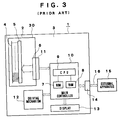
- Referring to Fig. 3 showing a conventional
thermal printer 1 by way of example, thethermal printer 1 is assembled by detachably mounting aprint unit 30 having a replaceablethermal print head 2, i.e., a driven unit, on amain unit 3. - The
thermal print head 2 of thethermal printer 1 has a plurality of linearly arrangedheating elements 4, a driving IC (integrated circuit) 5 connected to theheating elements 4, and aconnector 6 connected to the drivingIC 5 and to aninternal connector 11 for electrically connecting theprint unit 30 to amain controller 10 included in themain unit 3 of thethermal printer 1. - The
main controller 10 comprises a ROM (read-only memory) 7 initially and permanently storing pieces of information including control programs, a RAM (random-access memory) 8 temporarily storing printing data and such and allowing the retrieval of the stored data therefrom, and a CPU (central processing unit) 9 for processing data, connected to theROM 7 and theRAM 8. Theinternal connector 11, adriving mechanism 12 including a feed motor and such, not shown, adisplay 13 for displaying pieces of information including the condition of the power source, failure in feeding a recording sheet and the like, and anexternal connector 14 through which to receive printing data from an external apparatus are connected to themain controller 10. - The
main controller 10, thedriving mechanism 12 and the associated components of thethermal printer 1 form a printing system that drives the replaceablethermal print head 2 to print an image on a recording sheet, not shown. Acommunication cable 16 connected to anexternal apparatus 15, such as a personal computer, that provides printing data is detachably connected to theexternal connector 14 of thethermal printer 1. - The
thermal printer 1 receives printing data from theexternal apparatus 15 through thecommunication cable 16 and stores the same in theRAM 8 of themain controller 10. TheCPU 9 drives thethermal print head 2 and thedriving mechanism 12 according to the printing data stored in theRAM 8 and the control programs stored beforehand in theROM 7 to print images with thethermal print head 2 on recording sheets successively fed by thedriving mechanism 12. Theprint unit 30 is fabricated by mounting thethermal print head 2, theconnector 6 and the drivingIC 5 on a printed wiring board, not shown. - Since the
thermal print head 2 of thethermal printer 1 is expendable, theprint unit 30 must be replaced periodically with a new one. Usually, the number or the total length of recording sheets fed to theprint unit 30 is counted by a mechanical counter, not shown, included in thedriving mechanism 12 or by an electronic counter, not shown, comprised of theRAM 8 or theCPU 9 and included in themain controller 10, and a warning requesting the change of theprint unit 30 is displayed on thedisplay 13 when the count registered by the mechanical or electronic counter exceeds a predetermined limit value stored in theROM 7 or a serviceman checks the count registered by the mechanical or electronic counter during maintenance work. - This conventional
thermal printer 1 has the following problems. If theprint unit 30 is replaced with a new one before the warning is provided and the counter is not reset, or the counter is reset by mistake while thethermal print head 2 is in operation, a false count is registered by the counter. - In some cases, the
thermal printer 1 needs statistical data about the life of thethermal print head 2 and other components for quality control purposes. In such a case, a recording label, not shown, for recording the count when replacing theprint unit 30 is attached to theprint unit 30 and the count is entered in the recording label when theprint unit 30 is replaced. The serviceman collects periodically replacedprint units 30 carrying the recording labels recording the counts. - However, it is undesirable to put the operator under an obligation to enter the count in the recording label because recording the count is troublesome. Furthermore, the count entered in the recording label by the operator is not highly reliable because the operator is liable to fail in entering the count correctly, and collecting the recording labels with the count entered and processing the counts recorded on the thus collected recording labels by a personal computer or the like require very troublesome operations.
- Accordingly, it is a first object of the present invention to provide a print unit capable of holding data useful for the quality control of the printer and the print unit.
- A second object of the present invention is to provide a printer capable of readily and surly collecting data useful for the quality control of the printer and the print unit and of storing the collected data in its print unit.
- A third object of the present invention is to provide a printer capable of providing accurate information about the life of its print unit.
- The present invention provides a print unit capable of being detachably mounted on the main unit of a printer, comprising a driven unit to be driven by the main unit, and an erasable programmable data storage unit for storing data representing the operating experiences of the print unit to enable the print unit to hold data useful for the quality control of the printer and the print unit. After removing the print unit from the main unit of the printer, data stored in the data storage unit can be read.
- The present invention provides also a printer detachably provided with a print unit comprising a driven unit and an erasable programmable data storage unit for storing data representing the operating experiences of the print unit, and capable of driving the driven unit of the print unit to print an image on a recording sheet. The printer detects the operating experiences of the print unit, stores data representing the detected operating experiences of the print unit in the data storage unit to enable the print unit to hold data useful for the quality control of the printer and the print unit. Thus, the data useful for the quality control of the print unit can be readily and surely stored in the data storage unit, and the data can be read from the data storage unit and processed after removing the print unit from the main unit.
-
- Fig. 1 is a block diagram of the electric circuit of a thermal printer in a preferred embodiment according to the present invention;
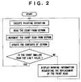
- Fig. 2 is a flow chart of control processes to be carried out by the thermal printer of Fig. 1; and
- Fig. 3 is a block diagram of the electric circuit of a conventional thermal printer.
- A thermal printer in a preferred embodiment according to the present invention will be described hereinafter with reference to Figs. 1 and 2, in which parts like or corresponding to those previously described with reference to Fig. 1 are denoted by the same reference characters and the description thereof will be omitted.
- Referring to Figs. 1 and 2, a
thermal printer 17 has aprint unit 30 detachably mounted on amain unit 19. - The
print unit 30 is formed by mounting athermal print head 18, i.e., a driven unit, formed by linearly arranging a plurality ofheating elements 4 and connecting a drivingIC 5 to theheating elements 4, an EEPROM (electrically erasable programmable read-only memory) 20, i.e., a data storage unit, for storing data, and aconnector 6 connected to the drivingIC 5 and the EEPROM 20 on a printed wiring board, not shown. - The
main unit 19 comprises amain controller 24 comprising aROM 21, aRAM 22 and aCPU 23 connected to theROM 21 and theRAM 22, aninternal connector 11, adriving mechanism 12, adisplay 13 and anexternal connector 14. theinternal connector 11, thedriving mechanism 12, thedisplay 13 and theexternal connector 14 are connected to themain controller 24. - In the
thermal printer 17, the printer mechanism for driving the detachablethermal head 18 so as to perform image printing on a recording sheet, not shown, comprises themain controller 24 and thedriving mechanism 12. Thethermal printer 17 includes a work measuring means for measuring the amount of work done by theprint unit 30 including thethermal print head 18, and a data writing means for writing data representing the amount of work measured by the work measuring means in theEEPROM 20. The work measuring means and the data writing means are such constituted as to be controlled by theCPU 23 of themain controller 24. More concretely, the work measuring means counts pulses representing printing data applied to thethermal print head 18, and the progressively increasing number of the pulses counted by the work measuring means is stored in theEEPROM 20. The number of the pulses stored in the EEPROM 20 is incremented by one every time one pulse is counted. - A limit value, i.e., a maximum allowable count, is stored beforehand in the
ROM 21 of themain unit 19 to limit the progressively increasing count stored in theEEPROM 20. A comparator included in theCPU 23 of themain controller 24 compares the count stored in theEEPROM 20 of theprint unit 30 and the limit value stored in theROM 21. Upon the detection of the increase of the count stored in theEEPROM 20 beyond the limit value, theCPU 23 executes a warning information output procedure to read warning information expressing that the count has exceeded the limit value from theROM 21 and gives the warning information to thedisplay 13 and anexternal apparatus 15, such as a personal computer. - The
CPU 23 drives thethermal print head 18 and thedriving mechanism 12 including a feed motor according to printing data received through thecommunication cable 16 from theexternal apparatus 15 and stored in theRAM 22, and a control program stored beforehand in theROM 21. Then, thedriving mechanism 12 feeds recording sheets successively and thethermal print head 18 prints images on the recording sheets. - The pulses representing printing data are counted by a counter, not shown, consisting of the
CPU 23, theROM 21 and theRAM 22. The count stored in the EEPROM 20 is incremented by one every time one pulse representing printing data is counted by the counter to update the count stored in theEEPROM 20. - After updating the count stored in the EEPROM 20, the
CPU 23 of themain unit 19 compares the limit value stored beforehand in theROM 21 and the count stored in theEEPROM 20. If the count stored in the EEPROM 20 is smaller than the limit value stored in theROM 21, the printing operation is continued. - Upon the detection of the increase of the count beyond the limit value while the
thermal printer 17 is in printing operation, theCPU 23 reads the warning information requesting the replacement of theprint unit 30 from theROM 21, and gives the warning information to thedisplay 13 to make thedisplay 13 display the warning information, to theexternal apparatus 15 or to thethermal print head 18 to make thethermal print head 18 print the warning information on the recording sheet. Thethermal printer 17 continues the printing operation even if the warning information is provided. - The warning information prompts the operator of the
thermal printer 17 to replace theprint unit 30. Thus, the time when theexpendable print unit 30 must be replaced with a new one can be accurately determined and it is possible to prompt the operator to replace theprint unit 30 with a new one after theprint unit 30 has done an appropriate amount of work. The operator need not perform troublesome work for resetting the counter, not shown. Since thethermal printer 17 need not be provided in itsdriving mechanism 12 with any counter for counting the number or the total length of recording sheets fed to theprint unit 30, thethermal printer 17 can be formed in a compact, lightweight construction, and the productivity of the production line for manufacturing thethermal printer 17 can be enhanced. - Since the count is stored in the
EEPROM 20 included in theprint unit 30 removed from themain unit 19, the statistical data of the life of thethermal print head 18 can be readily and surely obtained by reading the counts stored in theEEPROMs 20 of usedprint units 30 collected from the users. - Although the present invention has been described as applied to the
print unit 30 including thethermal print head 18 of thethermal printer 17, the present invention is not limited thereto in its practical application; the present invention is applicable also to other printers and other print units, such as end face light emission type electroluminescence printers (EL printers), end face light emission type electroluminescence print heads (EL heads), electrophotographic printers and organic photoconductive conductor drums (OPC drums) for electrophotography. - The EEPROM 20 included in the
print unit 30 in this embodiment as a data storage device may be substituted by a nonvolatile storage, such as a flash memory. - Although the
thermal printer 17 in this embodiment uses the number of pulses of printing data as the amount of work of thethermal print head 18, the work measuring means measures the amount of work and the data writing means writes the data representing the amount of work measured by the work measuring means in theEEPROM 20, the amount of work done by thethermal print head 18 may be represented by the number of electric driving pulses applied to thedriving mechanism 12 by themain controller 10 or the total operating time of thethermal print head 18 measured by themain controller 10. - Although the
printer unit 30 in this embodiment stores only the number of pulses representing the printing data is stored as an amount of work done by thethermal print head 18 in theEEPROM 20, it is possible to store various kinds of information, other than the number of pulses representing the amount of work done by thethermal print head 18, useful for the quality control of thethermal print head 18 and thethermal printer 17, such as the date and time of operation of thethermal print head 18, the number of replaced print units and the frequency of jamming may be stored in theEEPROM 20. - In the
thermal printer 17 in this embodiment, theEEPROM 20 for storing various kinds of information is incorporated into thethermal print head 18 and the data writing means incorporated into themain controller 24 included in themain unit 19 writes the amount of work done by thethermal print head 18 in theEEPROM 20 incorporated into theprinter unit 30 to facilitate the collection of various kinds of information. However, the present invention is not limited in its practical application to the foregoing embodiment specifically described herein; the data writing means may be incorporated, for instance, into the thermal print head to enable the thermal print head to record the amount of work when the same is used on a conventional printer. - Although the thermal printer in this embodiment continues its printing operation even after the
CPU 23 has decided that the count stored in theEEPROM 20 has exceeded the limit value and the warning information has been provided, the printing operation of thethermal printer 17 may be interrupted when the warning information is provided.
Claims (10)
- A print unit to be detachably mounted on the main unit of a printer, said print unit comprising;
a driven unit which is driven by said main unit; and
a data storage device capable of storing various kinds of information representing the condition of operation of said print unit provided by said main unit and allowing the updation of its contents. - A print unit according to claim 1, wherein said driven unit is a thermal print head.
- A print unit according to claim 1, wherein said data storage device is a nonvolatile memory.
- A print unit according to claim 3, wherein said nonvolatile memory is an EEPROM.
- A printer having a main unit; a print unit detachably mounted on said main unit; and a driven unit incorporated into said print unit and to be driven for printing an image on a recording sheet comprising:
work measuring means for detecting the condition of operation of said print unit;
a data storage device included in said print unit to store various kinds of information and allowing the updation of its contents; and
a data writing means incorporated into either said main unit or said print unit to write the data measured by the work measuring means in said data storage device. - A printer according to claim 5, wherein said driven unit is a thermal print head.
- A printer according to claim 5, wherein said data storage device is a nonvolatile memory.
- A printer according to claim 5, wherein said data storage device is an EEPROM.
- A printer according to claim 5, wherein said driven unit includes a thermal print head, and said work measuring means measures the number of pulses applied to said thermal print head.
- A printer according to claim 9, further comprising:
a comparing means for comparing the number of pulses applied to said thermal print head and measured by said work measuring means and a limit value corresponding to a maximum allowable number of pulses; and
a warning information output means for providing a warning information upon the increase of the number of pulses beyond the limit value.
Applications Claiming Priority (2)
| Application Number | Priority Date | Filing Date | Title |
|---|---|---|---|
| JP125563/93 | 1993-05-27 | ||
| JP5125563A JPH06336070A (en) | 1993-05-27 | 1993-05-27 | Printer unit and printer apparatus |
Publications (2)
| Publication Number | Publication Date |
|---|---|
| EP0626268A2 true EP0626268A2 (en) | 1994-11-30 |
| EP0626268A3 EP0626268A3 (en) | 1995-07-26 |
Family
ID=14913295
Family Applications (1)
| Application Number | Title | Priority Date | Filing Date |
|---|---|---|---|
| EP94303801A Withdrawn EP0626268A3 (en) | 1993-05-27 | 1994-05-26 | Printer with detachably mounted print unit. |
Country Status (3)
| Country | Link |
|---|---|
| US (1) | US5786828A (en) |
| EP (1) | EP0626268A3 (en) |
| JP (1) | JPH06336070A (en) |
Cited By (5)
| Publication number | Priority date | Publication date | Assignee | Title |
|---|---|---|---|---|
| EP0836947A2 (en) * | 1996-10-15 | 1998-04-22 | Hewlett-Packard Company | Method and apparatus for drop weight encoding |
| WO1998031548A1 (en) * | 1997-01-21 | 1998-07-23 | Hewlett-Packard Company | Ink container having electronic and mechanical features enabling plug compatibility between multiple supply sizes |
| EP0873873A2 (en) * | 1997-04-25 | 1998-10-28 | Hewlett-Packard Company | Image forming and office automation device consumable with memory |
| EP0882595A2 (en) * | 1997-06-04 | 1998-12-09 | Hewlett-Packard Company | Ink level estimation using drop count and ink level sense |
| CN1088012C (en) * | 1997-01-30 | 2002-07-24 | 惠普公司 | Ink container configured for use with compact supply station |
Families Citing this family (21)
| Publication number | Priority date | Publication date | Assignee | Title |
|---|---|---|---|---|
| US6040670A (en) * | 1998-02-05 | 2000-03-21 | Canon Kabushiki Kaisha | Controller for printer carriage motor |
| MY138350A (en) * | 1998-11-02 | 2009-05-29 | Seiko Epson Corp | Ink cartridge and printer using the same |
| CN101015996A (en) * | 1998-11-02 | 2007-08-15 | 精工爱普生株式会社 | Ink cartridge and printer using the same |
| AU2003268576B2 (en) * | 1998-11-02 | 2006-10-19 | Seiko Epson Corporation | Ink Cartridge and Printer Using the Same |
| JP2000218818A (en) * | 1998-11-26 | 2000-08-08 | Seiko Epson Corp | Ink container and printer using the same |
| JP2001187457A (en) * | 1998-11-26 | 2001-07-10 | Seiko Epson Corp | Printing device and cartridge |
| JP4314702B2 (en) | 1998-11-26 | 2009-08-19 | セイコーエプソン株式会社 | Printing apparatus, writing method, and printer |
| JP2000301738A (en) * | 1998-11-26 | 2000-10-31 | Seiko Epson Corp | Method for judging suitability of ink container and printing apparatus judging suitability of ink container |
| JP4395943B2 (en) | 1998-11-26 | 2010-01-13 | セイコーエプソン株式会社 | Printing apparatus and information management method thereof |
| DE19958946B4 (en) * | 1999-11-26 | 2006-11-09 | Francotyp-Postalia Gmbh | Procedure for piracy protection of a device |
| JP4433578B2 (en) * | 2000-06-29 | 2010-03-17 | ソニー株式会社 | CONNECTION DEVICE, CONNECTION METHOD, AND COMPUTER-READABLE PROGRAM STORAGE MEDIUM CONTAINING PROGRAM WITH CONNECTION FUNCTION |
| JP4023145B2 (en) † | 2000-12-05 | 2007-12-19 | セイコーエプソン株式会社 | Printing device, ink cartridge |
| US6467888B2 (en) | 2001-02-21 | 2002-10-22 | Illinois Tool Works Inc. | Intelligent fluid delivery system for a fluid jet printing system |
| CA2379725C (en) * | 2001-04-03 | 2007-06-12 | Seiko Epson Corporation | Ink cartridge |
| KR100437377B1 (en) * | 2002-02-15 | 2004-06-25 | 삼성전자주식회사 | An inkjet printer capable of checking as to whether nozzle is normal or not and method for informing about abnormal nozzle |
| US9296214B2 (en) | 2004-07-02 | 2016-03-29 | Zih Corp. | Thermal print head usage monitor and method for using the monitor |
| US8721203B2 (en) | 2005-10-06 | 2014-05-13 | Zih Corp. | Memory system and method for consumables of a printer |
| EP2133209A3 (en) * | 2008-06-12 | 2010-02-24 | Toshiba TEC Kabushiki Kaisha | Printing apparatus |
| JP2009297997A (en) * | 2008-06-12 | 2009-12-24 | Toshiba Tec Corp | Printer and control method of printer |
| JP2010058357A (en) * | 2008-09-03 | 2010-03-18 | Dainippon Printing Co Ltd | Thermal printer |
| JP2010221599A (en) * | 2009-03-24 | 2010-10-07 | Fujitsu Component Ltd | Printer |
Citations (7)
| Publication number | Priority date | Publication date | Assignee | Title |
|---|---|---|---|---|
| WO1990000974A1 (en) * | 1988-07-25 | 1990-02-08 | Siemens Aktiengesellschaft | Arrangement for printing devices for monitoring printing medium containers |
| EP0421806A2 (en) * | 1989-10-05 | 1991-04-10 | Canon Kabushiki Kaisha | An image forming apparatus |
| US5049898A (en) * | 1989-03-20 | 1991-09-17 | Hewlett-Packard Company | Printhead having memory element |
| US5068806A (en) * | 1988-12-02 | 1991-11-26 | Spectra-Physics, Inc. | Method of determining useful life of cartridge for an ink jet printer |
| JPH04275156A (en) * | 1991-03-01 | 1992-09-30 | Tokyo Electric Co Ltd | Ink jet printer and ink jet cartridge therefor |
| EP0541064A2 (en) * | 1991-11-04 | 1993-05-12 | Eastman Kodak Company | Thermal print head unit |
| EP0556011A2 (en) * | 1992-02-10 | 1993-08-18 | Canon Kabushiki Kaisha | Ink jet recording apparatus |
Family Cites Families (4)
| Publication number | Priority date | Publication date | Assignee | Title |
|---|---|---|---|---|
| US4345262A (en) * | 1979-02-19 | 1982-08-17 | Canon Kabushiki Kaisha | Ink jet recording method |
| JPS6469376A (en) * | 1987-09-10 | 1989-03-15 | Nec Corp | Printing history data storing circuit |
| JPH02231148A (en) * | 1988-11-04 | 1990-09-13 | Canon Inc | Driving method for recording head and recorder using the same method |
| US5276461A (en) * | 1989-04-18 | 1994-01-04 | Tokyo Electric Co., Ltd. | Electrophotographic printing device |
-
1993
- 1993-05-27 JP JP5125563A patent/JPH06336070A/en active Pending
-
1994
- 1994-05-26 EP EP94303801A patent/EP0626268A3/en not_active Withdrawn
-
1996
- 1996-04-02 US US08/626,756 patent/US5786828A/en not_active Expired - Lifetime
Patent Citations (7)
| Publication number | Priority date | Publication date | Assignee | Title |
|---|---|---|---|---|
| WO1990000974A1 (en) * | 1988-07-25 | 1990-02-08 | Siemens Aktiengesellschaft | Arrangement for printing devices for monitoring printing medium containers |
| US5068806A (en) * | 1988-12-02 | 1991-11-26 | Spectra-Physics, Inc. | Method of determining useful life of cartridge for an ink jet printer |
| US5049898A (en) * | 1989-03-20 | 1991-09-17 | Hewlett-Packard Company | Printhead having memory element |
| EP0421806A2 (en) * | 1989-10-05 | 1991-04-10 | Canon Kabushiki Kaisha | An image forming apparatus |
| JPH04275156A (en) * | 1991-03-01 | 1992-09-30 | Tokyo Electric Co Ltd | Ink jet printer and ink jet cartridge therefor |
| EP0541064A2 (en) * | 1991-11-04 | 1993-05-12 | Eastman Kodak Company | Thermal print head unit |
| EP0556011A2 (en) * | 1992-02-10 | 1993-08-18 | Canon Kabushiki Kaisha | Ink jet recording apparatus |
Non-Patent Citations (1)
| Title |
|---|
| PATENT ABSTRACTS OF JAPAN vol. 017 no. 074 (M-1366) ,15 February 1993 & JP-A-04 275156 (TOKYO ELECTRIC CO LTD) 30 September 1992, * |
Cited By (12)
| Publication number | Priority date | Publication date | Assignee | Title |
|---|---|---|---|---|
| US6305795B2 (en) | 1994-12-22 | 2001-10-23 | Winthrop D. Childers | Ink container having electronic and mechanical features enabling plug compatibility between multiple supply sizes |
| US5956057A (en) * | 1996-08-30 | 1999-09-21 | Hewlett-Packard Company | Ink container having electronic and mechanical features enabling plug compatibility between multiple supply sizes |
| EP0836947A2 (en) * | 1996-10-15 | 1998-04-22 | Hewlett-Packard Company | Method and apparatus for drop weight encoding |
| EP0836947A3 (en) * | 1996-10-15 | 1999-09-01 | Hewlett-Packard Company | Method and apparatus for drop weight encoding |
| US6655775B1 (en) | 1996-10-15 | 2003-12-02 | Hewlett-Packard Development Company, L.P. | Method and apparatus for drop weight encoding |
| WO1998031548A1 (en) * | 1997-01-21 | 1998-07-23 | Hewlett-Packard Company | Ink container having electronic and mechanical features enabling plug compatibility between multiple supply sizes |
| CN1088012C (en) * | 1997-01-30 | 2002-07-24 | 惠普公司 | Ink container configured for use with compact supply station |
| EP0873873A2 (en) * | 1997-04-25 | 1998-10-28 | Hewlett-Packard Company | Image forming and office automation device consumable with memory |
| EP0873873A3 (en) * | 1997-04-25 | 1999-10-13 | Hewlett-Packard Company | Image forming and office automation device consumable with memory |
| EP0882595A2 (en) * | 1997-06-04 | 1998-12-09 | Hewlett-Packard Company | Ink level estimation using drop count and ink level sense |
| EP0882595A3 (en) * | 1997-06-04 | 2000-03-29 | Hewlett-Packard Company | Ink level estimation using drop count and ink level sense |
| US6151039A (en) * | 1997-06-04 | 2000-11-21 | Hewlett-Packard Company | Ink level estimation using drop count and ink level sense |
Also Published As
| Publication number | Publication date |
|---|---|
| EP0626268A3 (en) | 1995-07-26 |
| JPH06336070A (en) | 1994-12-06 |
| US5786828A (en) | 1998-07-28 |
Similar Documents
| Publication | Publication Date | Title |
|---|---|---|
| US5786828A (en) | Detachable print unit having updatable condition memory and printer using the same | |
| EP1232868B1 (en) | Image forming apparatus having life information | |
| EP0873873B1 (en) | Image forming and office automation device consumable with memory | |
| US5489971A (en) | Method and apparatus for detecting an exchange period for parts within an electrophotographic printing apparatus | |
| DE60017650T2 (en) | Processing system for replaceable modules in a digital printer | |
| EP1080930B1 (en) | Printer, method of controlling it and data storage medium | |
| US4855754A (en) | Control device for an image recorder | |
| US4974238A (en) | Counter arrangement for determining the life of consumables in office equipment | |
| EP0919392B1 (en) | Printing apparatus, method of controlling it and storage medium | |
| CN1744991A (en) | Printer consumable product having data storage for static and dynamic calibration data, and methods | |
| US20180183974A1 (en) | Printer error checking with nfc technology | |
| CN111516397A (en) | Label paper identification method, device, equipment and readable storage medium | |
| US7430053B2 (en) | Tracking component usage in a printing device | |
| JP2002370378A (en) | Detection of printing recording material container | |
| US6798434B2 (en) | Printing device | |
| JP2007021787A (en) | Information processor having function of maintenance counter | |
| US6370340B1 (en) | Method and apparatus for monitoring parameters corresponding to operation of an electrophotographic marking machine | |
| US20070063013A1 (en) | Systems and methods for maintaining warranty claim information | |
| JP2008152541A (en) | Printer and log data management method | |
| JP2003191583A (en) | Printer | |
| JPS6280081A (en) | Recorder | |
| JP5619564B2 (en) | Verification device | |
| JP4307770B2 (en) | Label printer | |
| JPH0667483A (en) | Communication error preventing device for drum peripheral unit | |
| KR960008764B1 (en) | Printer head operating length detecting method |
Legal Events
| Date | Code | Title | Description |
|---|---|---|---|
| PUAI | Public reference made under article 153(3) epc to a published international application that has entered the european phase |
Free format text: ORIGINAL CODE: 0009012 |
|
| 17P | Request for examination filed |
Effective date: 19940603 |
|
| AK | Designated contracting states |
Kind code of ref document: A2 Designated state(s): BE DE ES FR GB |
|
| PUAL | Search report despatched |
Free format text: ORIGINAL CODE: 0009013 |
|
| AK | Designated contracting states |
Kind code of ref document: A3 Designated state(s): BE DE ES FR GB |
|
| RAP1 | Party data changed (applicant data changed or rights of an application transferred) |
Owner name: KABUSHIKI KAISHA TEC |
|
| 17Q | First examination report despatched |
Effective date: 19960701 |
|
| STAA | Information on the status of an ep patent application or granted ep patent |
Free format text: STATUS: THE APPLICATION IS DEEMED TO BE WITHDRAWN |
|
| 18D | Application deemed to be withdrawn |
Effective date: 19961112 |