EP0630128A2 - Autorate method for simultaneous transmission of voice and data - Google Patents
Autorate method for simultaneous transmission of voice and data Download PDFInfo
- Publication number
- EP0630128A2 EP0630128A2 EP94304180A EP94304180A EP0630128A2 EP 0630128 A2 EP0630128 A2 EP 0630128A2 EP 94304180 A EP94304180 A EP 94304180A EP 94304180 A EP94304180 A EP 94304180A EP 0630128 A2 EP0630128 A2 EP 0630128A2
- Authority
- EP
- European Patent Office
- Prior art keywords
- signal
- error
- threshold
- data
- predetermined
- Prior art date
- Legal status (The legal status is an assumption and is not a legal conclusion. Google has not performed a legal analysis and makes no representation as to the accuracy of the status listed.)
- Withdrawn
Links
Images


Classifications
-
- H—ELECTRICITY
- H04—ELECTRIC COMMUNICATION TECHNIQUE
- H04L—TRANSMISSION OF DIGITAL INFORMATION, e.g. TELEGRAPHIC COMMUNICATION
- H04L1/00—Arrangements for detecting or preventing errors in the information received
- H04L1/0001—Systems modifying transmission characteristics according to link quality, e.g. power backoff
- H04L1/0002—Systems modifying transmission characteristics according to link quality, e.g. power backoff by adapting the transmission rate
-
- H—ELECTRICITY
- H03—ELECTRONIC CIRCUITRY
- H03M—CODING; DECODING; CODE CONVERSION IN GENERAL
- H03M13/00—Coding, decoding or code conversion, for error detection or error correction; Coding theory basic assumptions; Coding bounds; Error probability evaluation methods; Channel models; Simulation or testing of codes
- H03M13/35—Unequal or adaptive error protection, e.g. by providing a different level of protection according to significance of source information or by adapting the coding according to the change of transmission channel characteristics
-
- H—ELECTRICITY
- H04—ELECTRIC COMMUNICATION TECHNIQUE
- H04L—TRANSMISSION OF DIGITAL INFORMATION, e.g. TELEGRAPHIC COMMUNICATION
- H04L1/00—Arrangements for detecting or preventing errors in the information received
- H04L1/20—Arrangements for detecting or preventing errors in the information received using signal quality detector
-
- H—ELECTRICITY
- H04—ELECTRIC COMMUNICATION TECHNIQUE
- H04M—TELEPHONIC COMMUNICATION
- H04M11/00—Telephonic communication systems specially adapted for combination with other electrical systems
- H04M11/06—Simultaneous speech and data transmission, e.g. telegraphic transmission over the same conductors
-
- Y—GENERAL TAGGING OF NEW TECHNOLOGICAL DEVELOPMENTS; GENERAL TAGGING OF CROSS-SECTIONAL TECHNOLOGIES SPANNING OVER SEVERAL SECTIONS OF THE IPC; TECHNICAL SUBJECTS COVERED BY FORMER USPC CROSS-REFERENCE ART COLLECTIONS [XRACs] AND DIGESTS
- Y02—TECHNOLOGIES OR APPLICATIONS FOR MITIGATION OR ADAPTATION AGAINST CLIMATE CHANGE
- Y02D—CLIMATE CHANGE MITIGATION TECHNOLOGIES IN INFORMATION AND COMMUNICATION TECHNOLOGIES [ICT], I.E. INFORMATION AND COMMUNICATION TECHNOLOGIES AIMING AT THE REDUCTION OF THEIR OWN ENERGY USE
- Y02D30/00—Reducing energy consumption in communication networks
- Y02D30/50—Reducing energy consumption in communication networks in wire-line communication networks, e.g. low power modes or reduced link rate
Definitions
- the present invention relates to data communications equipment, e.g., modems.
- this invention relates to the transmission of both voice and data signals over the same communications facility at the same time.
- each modem of a data connection continually tests the quality of the communications channel to adjust the data transmission rate, i.e., the bit rate, between the modems. For example, if the data signal begins to experience an increase in errors, i.e., a higher error rate, then the modems will negotiate a lower data rate between themselves. Conversely, if over a period of time the error rate is lower than a predetermined threshold, the modems will negotiate a higher data rate between themselves.
- the prior-art method of autorating results in the receiving modem erroneously computing an error signal that is proportional to the transmitted voice signal and not the ambient noise of the communications channel. Consequently, the prior-art method of auto-rating is ineffective in a simultaneous voice and data communications system.
- an autorating method and apparatus in which the evaluation of ambient noise on a communications channel only occurs during silent periods of the voice signal. When a silent period is detected, noise statistics of the communications channel are then collected.
- an autorate feature is implemented in one illustrative embodiment by adding a silence detector to the receiver circuitry of at least one of the modems.
- the silence detector provides an enabling signal in such a way that noise statistics are only accumulated during intervals of silence. If the resulting noise statistics exceed a predetermined threshold, e.g., the communications channel is too noisy, the receiving modem negotiates a lower data rate with the transmitting modem. Conversely, if the resulting noise statistics are lower than a predetermined threshold, the receiving modem negotiates a higher data rate with the transmitting modem.
- a transmitting modem provides the enabling signal to the receiving modem during periods of silence.
- the enabling signal is a control message passed to the receiving modem on a secondary communications channel.
- the receiving modem then accumulates error statistics in order to determine whether to change the data rate over the communications channel.
- FIG. 1 An embodiment of the inventive concept is shown in FIG. 1.
- a modulated simultaneous voice and data input signal is received from a communications channel and applied to demodulator 210 which develops the in-phase and quadrature components. Those are applied to slicer 220, which identifies the symbols, i.e., maps the received signal point to the closest data symbol from the currently selected symbol constellation (not shown). It is assumed that slicer 220 stores a number, or set, of symbol constellations, of which one symbol constellation is the currently selected constellation, which is controlled by CPU 290 (discussed below). Slicer 220 provides the identified symbols to 2-to-1 de-mapper 230.
- FIG. 1 An embodiment of the inventive concept is shown in FIG. 1.
- FIG. 1 As disclosed in the above-mentioned co-pending patent application a modulated simultaneous voice and data input signal is received from a communications channel and applied to demodulator 210 which develops the in-phase and quadrature components. Those are applied to slicer 220, which identifies the symbols,
- 1 includes 1-to-2 mapper 240 that is responsive to the symbols developed by slicer 220.
- the output of mapper 240 is a set of in-phase and quadrature components for the identified symbols.
- the outputs of mapper 240 are subtracted from the outputs of demodulator 210 in subtractors 250 and 260 to provide a pair of analog samples on lines 251 and 261. These outputs are applied to 2-to-1 de-mapper 270, which recombines the analog samples to form the original analog signal, e.g., a voice signal, on line 271.
- slicer 220 provides an error signal on line 221 to autorate element 280.
- This error signal represents the error distance between each received signal point and the closest symbol of the currently selected constellation.
- FIG. 2 a more detailed block diagram of autorate element 280 is shown.
- the error signal from slicer 220 is applied to filter 110, which both squares and averages the error signal to generate a signal on line 111 that is proportional to the mean-squared-error (MSE).
- MSE mean-squared-error
- threshold detector 115 when operating in accordance with the invention (described below), compares the MSE signal to a predetermined low threshold and a predetermined high threshold.
- Threshold detector 115 provides two output signals to counter 120, the signal on line 117 representing when the MSE signal is above the high threshold, and the signal on line 118 representing when the MSE signal is below the low threshold.
- Counter 120 counts the number of times that either the MSE signal is above or below these predetermined thresholds and provides two rate change signals on lines 281 and 282, respectively.
- the current count stored in counter 120 exceeds a predetermined high error number
- counter 120 signals CPU 290 via line 281 to change the data bit rate in the "down" direction.
- counter 120 signals CPU 290 via line 281 to change the data bit rate in the "up" direction.
- CPU 290 In response to either of these rate change signals, resets counter 120 via a signal on line 291, and initiates a negotiation with a far modem (not shown) in accordance with CCITT standards to change the data bit rate in the appropriate direction. In addition, once the data bit rate is changed, CPU 290 provides a signal to slicer 220 to change the selected constellation to one that provides the new data bit rate, i.e., of bits/symbol.
- CPU 290 occasionally resets counter 120, via a signal on line 291, even if there is no signal, via line 281, to change the data rate. This occasional resetting of counter 120 is necessary otherwise counter 120 will continue to accumulate noise statistics and eventually signal a data rate change even though the quality of the communications channel is acceptable. For example, it can be a priori determined that noise statistics are accumulated over a one second time interval during which an enabling signal on line 46 is active (discussed below). If CPU 290 receives no data rate change signal after one second, CPU 290 then resets counter 120. On the other hand, if CPU 290 receives a data rate change signal before the one second expires, CPU 290 then restarts the measurement of the one second time interval.
- CPU 290 only measures this one second time interval when the enabling signal on line 146 is active.
- counter 120 can be incremented or decremented in a "leaky" fashion. In particular, when the MSE signal is above a predetermined threshold, counter 120 is incremented by an amount K . However, when the MSE signal is below the predetermined amount, counter 120 is decremented by an amount J , where J ⁇ K . This ensures that over a long period of time counter 120 will decrement notwithstanding the presence of burst noise on the communications channel.
- threshold detector 115 only compares the MSE signal to a predetermined low threshold and a predetermined high threshold during a particular time interval.
- the particular time interval, in which threshold detector 115 operates, is under the control of voice energy detector 145.
- the latter receives the output of de-mapper 270 and estimates whether or not a voice signal is being received.
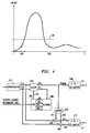
- a typical frequency spectrum of a voice signal is shown in FIG. 3.
- voice energy detector 145 comprises a simple band pass filter, which provides a signal on line 146 if the energy of the voice signal in the 200 to 500 Hz frequency range is below a predetermined amount of energy, represented by line 148 from FIG. 3.
- threshold detector 115 only functions when the energy of the received voice signal is low, e.g., during periods of silence.
- autorate element 280 estimates the amount of noise present on the communications channel only when the received voice signal comprises a small amount of energy. Consequently, any errors in the received signal are then attributed to the result of a noise signal rather than a person talking.
- FIG. 4 Another embodiment of the invention is shown in FIG. 4.
- no voice signal is applied to autorate element 380.
- CPU 390 receives control channel information as is known in the prior art from the far modem (not shown) via a signal on line 289.
- a control channel, or secondary channel provides control and signaling information between the two modems.
- This secondary channel can be time division multiplexed with the data stream or use a part of the frequency spectrum.
- the secondary channel allows the transmitting modem to signal the receiving modem when no voice is being transmitted simultaneously with the data signal (discussed below).
- CPU 390 when CPU 390 receives a message, or enabling signal, from the transmitting modem that no voice signal is being transmitted, CPU 390 enables autorate element 380 via a signal on line 294.
- Autorate element 380 is shown in more detail in FIG. 5 and functions in a similar fashion to autorate element 280 described above, except that the operation of threshold detector 315 is controlled by CPU 390, which is responsive to the above-mentioned enabling signal from the far modem. Otherwise, CPU 390 functions as described above.
- FIG. 6 An illustrative method for use in conjunction with the embodiment of FIG. 4 is shown in FIG. 6.
- the method shown in FIG. 6 assumes a data connection between a far-end modem, which is transmitting a simultaneous voice and data signal, and a near-end modem, which is receiving the simultaneous voice and data signal. It is also assumed that a secondary channel exists as is known in the prior art for communication of signaling and control information between the far-end modem and the near-end modem. As disclosed in the above-mentioned co-pending patent application of Gordon Bremer and Kenneth D. Ko, the far-end, or transmitting, modem has access to all the information in order to make a determination of whether or not a voice signal is being communicated to the near-end, or receiving, modem.
- step 605 the far-end modem monitors its transmission to detect a silence interval. If a silence interval is detected, the farend modem transmits a "silence indicator" message to the near-end modem in step 610 on a secondary channel. However, if a silence interval is not detected, the far-end modem does not transmit the silence indicator message in step 615.
- CPU 390 monitors the secondary channel for the silence indicator message in step 640. If no silence indicator message is received, CPU 390 disables autorate element 380 in step 645. However, if a silence indicator message is received, CPU 390 enables autorate element 380 in step 650. In other words, the silence indicator message enables and disables the operation of any apparatus or method that estimates the ambient noise of the communications channel.
- the invention is illustrated herein as being implemented with discrete functional building blocks, e.g., autorate element 280, etc., the functions of any one or more of those building blocks can be carried out using one or more appropriate programmed processors.
- the threshold values and error numbers can vary as a function of the selected constellation, i.e., data rate, and it is not limited to the use of MSE estimation.
- other forms of voice signal detectors can be used, e.g., looking for pitch periods in the voice signal.
- other forms of secondary channels are also possible, e.g., dithering a signal point constellation by adding a signal point to the constellation.
Abstract
In a simultaneous voice and data communications system comprising two modems, an autorate feature is implemented in one illustrative method by adding a silence detector to the receiver circuitry of at least one of the modems in such a way that noise statistics for the communications channel are only accumulated during intervals of silence. If the resulting noise statistics exceed a predetermined threshold, i.e., the communications channel is too noisy, the receiving modem negotiates a lower data rate with the transmitting modem. In another illustrative method, the transmitting modem provides a signal, which represents an interval of silence, to the receiving modem. Upon receipt of the signal, the receiving modem accumulates error statistics in order to determine if the communications channel is too noisy.
Description
- The present invention relates to data communications equipment, e.g., modems. In particular, this invention relates to the transmission of both voice and data signals over the same communications facility at the same time.
- A standard feature in most modems today is the "autorate" feature. In particular, each modem of a data connection continually tests the quality of the communications channel to adjust the data transmission rate, i.e., the bit rate, between the modems. For example, if the data signal begins to experience an increase in errors, i.e., a higher error rate, then the modems will negotiate a lower data rate between themselves. Conversely, if over a period of time the error rate is lower than a predetermined threshold, the modems will negotiate a higher data rate between themselves.
- A number of prior art autorating techniques are illustrated in U.S. Patent No. 4,756,007 issued July 5, 1988 to Qureshi et al.; U.S. Patent No. 4,991,184 issued February 5, 1991 to Hashimoto; and U.S. Patent No. 5,007,047 issued April 9, 1991 to Sridhar et al. Generally speaking, the prior art approach operates in the following manner. The receiving modem performs a "slicing" operation on each received signal point. This slicing operation simply estimates the closest symbol to the received signal point from a known constellation of symbols. This is known also as a "hard decision." The magnitude of the deviation of the received signal point from the closest symbol is assumed to be proportional to the ambient noise condition of the communications channel. When the ambient noise condition of the channel exceeds in either direction a set of predetermined limits, the modems negotiate between themselves a change in the data rate to accommodate the estimated ambient noise of the communications channel.
- The co-pending, commonly assigned, U.S. Patent application of Gordon Bremer and Kenneth D. Ko, entitled "Simultaneous Analog and Digital Communication," serial No. 08/076505, filed on June 14, 1993, which is hereby incorporated by reference, discloses a simultaneous voice and data communication system in which a voice signal is simultaneously added to a data signal for transmission over a communications channel to a receiving modem. Generally, in each signaling interval, T, the data signal is represented by a data symbol, which is a reference signal point value. To this data symbol is added a voice signal vector, which represents the voice signal. The addition of the voice signal vector to the data symbol results in a signal point being selected that is a function of both the data signal and the voice signal in each signaling interval T.
- Unfortunately, since the selected signal point is different from the selected data symbol, the prior-art method of autorating results in the receiving modem erroneously computing an error signal that is proportional to the transmitted voice signal and not the ambient noise of the communications channel. Consequently, the prior-art method of auto-rating is ineffective in a simultaneous voice and data communications system.
- In accordance with the invention, an autorating method and apparatus is disclosed in which the evaluation of ambient noise on a communications channel only occurs during silent periods of the voice signal. When a silent period is detected, noise statistics of the communications channel are then collected.
- In a simultaneous voice and data communications system comprising two modems, an autorate feature is implemented in one illustrative embodiment by adding a silence detector to the receiver circuitry of at least one of the modems. The silence detector provides an enabling signal in such a way that noise statistics are only accumulated during intervals of silence. If the resulting noise statistics exceed a predetermined threshold, e.g., the communications channel is too noisy, the receiving modem negotiates a lower data rate with the transmitting modem. Conversely, if the resulting noise statistics are lower than a predetermined threshold, the receiving modem negotiates a higher data rate with the transmitting modem.
- In another embodiment of the invention, a transmitting modem provides the enabling signal to the receiving modem during periods of silence. In particular, the enabling signal is a control message passed to the receiving modem on a secondary communications channel. In response to receiving the enabling signal, the receiving modem then accumulates error statistics in order to determine whether to change the data rate over the communications channel.
-
- FIG. 1 shows a receiver embodying the principles of the invention;
- FIG. 2 shows a block diagram of
autorate block 280 shown in FIG. 1; - FIG. 3 illustrates a voice signal's frequency spectrum;
- FIG. 4 shows another receiver embodying the principles of the invention;
- FIG. 5 shows a block diagram of
autorate block 380 shown in FIG. 4; and - FIG. 6 illustrates a method for use in the embodiment of FIG. 4.
- An embodiment of the inventive concept is shown in FIG. 1. As disclosed in the above-mentioned co-pending patent application a modulated simultaneous voice and data input signal is received from a communications channel and applied to
demodulator 210 which develops the in-phase and quadrature components. Those are applied toslicer 220, which identifies the symbols, i.e., maps the received signal point to the closest data symbol from the currently selected symbol constellation (not shown). It is assumed that slicer 220 stores a number, or set, of symbol constellations, of which one symbol constellation is the currently selected constellation, which is controlled by CPU 290 (discussed below).Slicer 220 provides the identified symbols to 2-to-1de-mapper 230. In addition, FIG. 1 includes 1-to-2mapper 240 that is responsive to the symbols developed byslicer 220. The output ofmapper 240 is a set of in-phase and quadrature components for the identified symbols. The outputs ofmapper 240 are subtracted from the outputs ofdemodulator 210 insubtractors lines 251 and 261. These outputs are applied to 2-to-1de-mapper 270, which recombines the analog samples to form the original analog signal, e.g., a voice signal, online 271. - As shown in FIG. 1,
slicer 220 provides an error signal online 221 toautorate element 280. This error signal represents the error distance between each received signal point and the closest symbol of the currently selected constellation. Turning now to FIG. 2, a more detailed block diagram ofautorate element 280 is shown. The error signal fromslicer 220 is applied tofilter 110, which both squares and averages the error signal to generate a signal online 111 that is proportional to the mean-squared-error (MSE). This MSE signal is applied tothreshold detector 115. The latter, when operating in accordance with the invention (described below), compares the MSE signal to a predetermined low threshold and a predetermined high threshold.Threshold detector 115 provides two output signals to counter 120, the signal online 117 representing when the MSE signal is above the high threshold, and the signal on line 118 representing when the MSE signal is below the low threshold.Counter 120 counts the number of times that either the MSE signal is above or below these predetermined thresholds and provides two rate change signals onlines counter 120 exceeds a predetermined high error number, counter 120signals CPU 290 vialine 281 to change the data bit rate in the "down" direction. On the other hand, when the current count stored incounter 120 exceeds a predetermined low error number, counter 120signals CPU 290 vialine 281 to change the data bit rate in the "up" direction. In response to either of these rate change signals,CPU 290 resetscounter 120 via a signal online 291, and initiates a negotiation with a far modem (not shown) in accordance with CCITT standards to change the data bit rate in the appropriate direction. In addition, once the data bit rate is changed,CPU 290 provides a signal to slicer 220 to change the selected constellation to one that provides the new data bit rate, i.e., of bits/symbol. - In addition,
CPU 290 occasionally resetscounter 120, via a signal online 291, even if there is no signal, vialine 281, to change the data rate. This occasional resetting ofcounter 120 is necessary otherwisecounter 120 will continue to accumulate noise statistics and eventually signal a data rate change even though the quality of the communications channel is acceptable. For example, it can be a priori determined that noise statistics are accumulated over a one second time interval during which an enabling signal on line 46 is active (discussed below). IfCPU 290 receives no data rate change signal after one second,CPU 290 then resetscounter 120. On the other hand, ifCPU 290 receives a data rate change signal before the one second expires,CPU 290 then restarts the measurement of the one second time interval. As mentioned above,CPU 290 only measures this one second time interval when the enabling signal online 146 is active. Alternatively,counter 120 can be incremented or decremented in a "leaky" fashion. In particular, when the MSE signal is above a predetermined threshold,counter 120 is incremented by an amount K. However, when the MSE signal is below the predetermined amount,counter 120 is decremented by an amount J, where J<K. This ensures that over a long period oftime counter 120 will decrement notwithstanding the presence of burst noise on the communications channel. - As noted above, and in accordance with the invention,
threshold detector 115 only compares the MSE signal to a predetermined low threshold and a predetermined high threshold during a particular time interval. The particular time interval, in whichthreshold detector 115 operates, is under the control ofvoice energy detector 145. The latter receives the output ofde-mapper 270 and estimates whether or not a voice signal is being received. A typical frequency spectrum of a voice signal is shown in FIG. 3. Illustratively,voice energy detector 145 comprises a simple band pass filter, which provides a signal online 146 if the energy of the voice signal in the 200 to 500 Hz frequency range is below a predetermined amount of energy, represented byline 148 from FIG. 3. In other words,threshold detector 115 only functions when the energy of the received voice signal is low, e.g., during periods of silence. As a result,autorate element 280 estimates the amount of noise present on the communications channel only when the received voice signal comprises a small amount of energy. Consequently, any errors in the received signal are then attributed to the result of a noise signal rather than a person talking. - Another embodiment of the invention is shown in FIG. 4. In this embodiment, no voice signal is applied to
autorate element 380. Instead,CPU 390 receives control channel information as is known in the prior art from the far modem (not shown) via a signal online 289. In particular, a control channel, or secondary channel, provides control and signaling information between the two modems. This secondary channel can be time division multiplexed with the data stream or use a part of the frequency spectrum. In the context of this invention, the secondary channel allows the transmitting modem to signal the receiving modem when no voice is being transmitted simultaneously with the data signal (discussed below). - In particular, when
CPU 390 receives a message, or enabling signal, from the transmitting modem that no voice signal is being transmitted,CPU 390 enablesautorate element 380 via a signal online 294.Autorate element 380 is shown in more detail in FIG. 5 and functions in a similar fashion toautorate element 280 described above, except that the operation ofthreshold detector 315 is controlled byCPU 390, which is responsive to the above-mentioned enabling signal from the far modem. Otherwise,CPU 390 functions as described above. - An illustrative method for use in conjunction with the embodiment of FIG. 4 is shown in FIG. 6. The method shown in FIG. 6 assumes a data connection between a far-end modem, which is transmitting a simultaneous voice and data signal, and a near-end modem, which is receiving the simultaneous voice and data signal. It is also assumed that a secondary channel exists as is known in the prior art for communication of signaling and control information between the far-end modem and the near-end modem. As disclosed in the above-mentioned co-pending patent application of Gordon Bremer and Kenneth D. Ko, the far-end, or transmitting, modem has access to all the information in order to make a determination of whether or not a voice signal is being communicated to the near-end, or receiving, modem. For example, in the above-mentioned co-pending patent application of Gordon Bremer and Kenneth D. Ko, a voice signal is added to the signal point coordinates of a selected data symbol. Therefore, if only the signal points corresponding to selected data symbols are being transmitted, the transmitting modem knows that no voice signal is present.
- In
step 605, the far-end modem monitors its transmission to detect a silence interval. If a silence interval is detected, the farend modem transmits a "silence indicator" message to the near-end modem in step 610 on a secondary channel. However, if a silence interval is not detected, the far-end modem does not transmit the silence indicator message instep 615. - In the near-end modem,
CPU 390 monitors the secondary channel for the silence indicator message in step 640. If no silence indicator message is received,CPU 390 disablesautorate element 380 instep 645. However, if a silence indicator message is received,CPU 390 enablesautorate element 380 instep 650. In other words, the silence indicator message enables and disables the operation of any apparatus or method that estimates the ambient noise of the communications channel. - The foregoing merely illustrates the principles of the invention and it will thus be appreciated that those skilled in the art will be able to devise numerous alternative arrangements which, although not explicitly described herein, embody the principles of the invention and are within its spirit and scope.
- For example, although the invention is illustrated herein as being implemented with discrete functional building blocks, e.g.,
autorate element 280, etc., the functions of any one or more of those building blocks can be carried out using one or more appropriate programmed processors. In addition, the threshold values and error numbers can vary as a function of the selected constellation, i.e., data rate, and it is not limited to the use of MSE estimation. Also, other forms of voice signal detectors can be used, e.g., looking for pitch periods in the voice signal. Finally, other forms of secondary channels are also possible, e.g., dithering a signal point constellation by adding a signal point to the constellation.
Claims (14)
- A method for autorating for use in data communications equipment, where the data communications equipment is coupled to a distant endpoint through a communications channel, the method comprising the steps of:
receiving a signal from the communications channel, where the signal represents a sequence of signal points;
generating an error signal that is a function of the difference between each one of the received sequence of signal points and a respective one of a number of signal points from a signal space;
evaluating the error signal during at least one time interval to provide an estimate of the ambient noise of the communications channel, where the occurrence of the at least one time interval is a function of an enabling signal; and
changing the data bit rate over the communications channel as a function of said ambient noise estimate. - The method of claim 1 wherein the evaluating step includes the steps of:
comparing the error signal to a first threshold;
counting the number of times the error signal exceeds the first threshold; and
providing the estimate of the ambient noise when the number of times the error signal exceeds the first threshold is greater than a predetermined second threshold. - The method of claim 2 wherein the step of counting includes the step of resetting the count if a predetermined time interval expires before the predetermined second threshold is exceeded.
- The method of claim 2 wherein the step of counting is performed so that over a long period of time said count of the number of times the error signal exceeds the first threshold is occasionally decremented before the count exceeds the predetermined second threshold.
- The method of claim 2 wherein the received signal includes portions of a data signal and at least one other signal, and the enabling signal is an estimate of the presence of the at least one other signal in any time interval in such a way that the error signal is evaluated only when the enabling signal provides an estimate that the at least one other signal is not present.
- The method of claim 5 wherein the enabling signal provides an estimate of the presence of the at least one other signal by comparing the energy level of the at least one other signal to a predetermined threshold.
- The method of claim 6 wherein the at least one other signal is a voice signal and the enabling signal is representative of the occurrence of silent intervals in the voice signal.
- The method of claim 6 further comprising the steps of:
filtering the at least one other signal to estimate the energy distribution of the at least one other signal in a first frequency range; and
generating the enabling signal when the energy distribution in the first frequency range is below a predetermined threshold. - The method of claim 8 wherein the first frequency range is within the frequency spectrum of a voice signal.
- The method of claim 1 wherein the enabling signal is the result of a message received from the distant endpoint.
- Apparatus for use in data communications equipment comprising:
means for demodulating a received signal from a communications channel to provide a sequence of signal points;
means for processing the sequence of signal points to provide a data signal, a second signal, and an error signal, where the error signal represents an estimation of the deviation of each signal point of the sequence from one of a number of data symbols, where each data symbol represents a respective one of a number of reference signal points;
means for processing the error signal to provide an autorate signal; and
means responsive to the autorate signal for changing the data bit rate communicated over the communications channel;
where the means for processing is enabled in at least one of a number of time intervals, K , as a function of the second signal. - The apparatus of claim 15 wherein the means for processing the error signal includes:
means for filtering the error signal to provide a signal representative of the mean-squared-error of said deviation;
means for comparing the signal representative of the mean-squared-error to a threshold in such a way that the autorate signal represents when the mean-squared-error exceeds the threshold a predetermined number of times within a predetermined interval; and
means responsive to the second signal for controlling the means for time comparing. - The apparatus of claim 12 wherein the second signal is a voice signal and the means responsive enables the means for comparing during intervals of silence in the voice signal.
- The apparatus of claim 13 wherein the means responsive enables the means for comparing whenever the energy of the voice signal is below a predetermined amount over a predefined frequency range.
Applications Claiming Priority (2)
| Application Number | Priority Date | Filing Date | Title |
|---|---|---|---|
| US7652593A | 1993-06-14 | 1993-06-14 | |
| US76525 | 1993-06-14 |
Publications (2)
| Publication Number | Publication Date |
|---|---|
| EP0630128A2 true EP0630128A2 (en) | 1994-12-21 |
| EP0630128A3 EP0630128A3 (en) | 1997-05-02 |
Family
ID=22132570
Family Applications (1)
| Application Number | Title | Priority Date | Filing Date |
|---|---|---|---|
| EP94304180A Withdrawn EP0630128A3 (en) | 1993-06-14 | 1994-06-10 | Autorate method for simultaneous transmission of voice and data. |
Country Status (8)
| Country | Link |
|---|---|
| US (1) | US5671250A (en) |
| EP (1) | EP0630128A3 (en) |
| JP (1) | JPH0750653A (en) |
| KR (1) | KR950002306A (en) |
| CN (1) | CN1111861A (en) |
| CA (1) | CA2125511A1 (en) |
| IL (1) | IL110004A (en) |
| TW (1) | TW245869B (en) |
Families Citing this family (32)
| Publication number | Priority date | Publication date | Assignee | Title |
|---|---|---|---|---|
| US5684834A (en) * | 1993-06-14 | 1997-11-04 | Paradyne Corporation | Simultaneous analog and digital communication using fractional rate encoding |
| US6064693A (en) * | 1997-02-28 | 2000-05-16 | Data Race, Inc. | System and method for handling underrun of compressed speech frames due to unsynchronized receive and transmit clock rates |
| US6647058B1 (en) * | 1997-06-23 | 2003-11-11 | Paradyne Corporation | Performance customization system and process for optimizing XDSL performance |
| US7248626B2 (en) | 1997-12-05 | 2007-07-24 | Paradyne Corporation | System and method of communication via embedded modulation |
| US9432172B2 (en) | 1997-12-05 | 2016-08-30 | Rembrandt Wireless Technologies, Lp | System and method of communication using at least two modulation methods |
| US7076003B1 (en) * | 1999-03-03 | 2006-07-11 | Agere Systems Inc. | Constellation design for modem receiver |
| US6553518B1 (en) | 1999-03-08 | 2003-04-22 | International Business Machines Corporation | Severe error detectors, methods and computer program products that use constellation specific error event thresholds to detect severe error events during demodulation of a signal comprising symbols from a plurality of symbol constellations |
| US6661847B1 (en) | 1999-05-20 | 2003-12-09 | International Business Machines Corporation | Systems methods and computer program products for generating and optimizing signal constellations |
| US6839382B1 (en) | 1999-10-29 | 2005-01-04 | International Business Machines Corporation | System, methods and computer program products for identifying digital impairments in modem signals using signature analysis and signal level comparison analysis |
| US6754258B1 (en) | 1999-10-29 | 2004-06-22 | International Business Machines Corporation | Systems, methods and computer program products for averaging learned levels in the presence of digital impairments based on patterns |
| US6792040B1 (en) | 1999-10-29 | 2004-09-14 | International Business Machines Corporation | Modems having a dual power mode capability and methods of operating same |
| US6823017B1 (en) | 1999-10-29 | 2004-11-23 | International Business Machines Corporation | Systems, methods and computer program products for filtering glitches from measured values in a sequence of code points |
| US6765955B1 (en) | 1999-10-29 | 2004-07-20 | International Business Machines Corporation | Methods, systems and computer program products establishing a communication configuration for a modem connection to compensate for echo noise |
| US6816545B1 (en) | 1999-10-29 | 2004-11-09 | International Business Machines Corporation | Systems, methods and computer program products for identifying digital impairments in modems based on clusters and/or skips in pulse code modulation signal levels |
| US6662322B1 (en) | 1999-10-29 | 2003-12-09 | International Business Machines Corporation | Systems, methods, and computer program products for controlling the error rate in a communication device by adjusting the distance between signal constellation points |
| US6650657B1 (en) | 1999-10-29 | 2003-11-18 | International Business Machines Corporation | Systems, methods and computer program products for identifying digital impairments in modem signals |
| US6826157B1 (en) | 1999-10-29 | 2004-11-30 | International Business Machines Corporation | Systems, methods, and computer program products for controlling data rate reductions in a communication device by using a plurality of filters to detect short-term bursts of errors and long-term sustainable errors |
| US6823004B1 (en) | 1999-10-29 | 2004-11-23 | International Business Machines Corporation | Methods, systems and computer program products for monitoring performance of a modem during a connection |
| US6792004B1 (en) | 1999-10-29 | 2004-09-14 | International Business Machines Corporation | Systems, methods and computer program products for averaging learned levels in the presence of robbed-bit signaling based on proximity |
| US6505222B1 (en) | 1999-10-29 | 2003-01-07 | International Business Machines Corporation | Systems methods and computer program products for controlling undesirable bias in an equalizer |
| US6967995B1 (en) | 1999-10-29 | 2005-11-22 | International Business Machines Corporation | Methods, systems and computer program products for carrier drop detection using a variable threshold |
| US6611563B1 (en) | 1999-10-29 | 2003-08-26 | International Business Machines Corporation | Systems, methods and computer program products for data mode refinement of modem constellation points |
| US6418160B1 (en) | 2000-03-29 | 2002-07-09 | Sbc Technology Resources, Inc. | Method for testing a communication channel |
| US20020114382A1 (en) * | 2000-11-29 | 2002-08-22 | Dan Goren | Parallel optimal data rate setting in a modem pool environment |
| DE10121912C2 (en) * | 2001-05-05 | 2003-05-22 | Phoenix Contact Gmbh & Co | Method for central data rate setting in a data transmission system and device for central data rate setting |
| US20030003905A1 (en) * | 2001-06-20 | 2003-01-02 | Shvodian William M. | System and method for providing signal quality feedback in a wireless network |
| US8149904B2 (en) * | 2002-01-24 | 2012-04-03 | Broadcom Corporation | Asymmetric digital subscriber line modem apparatus and methods therefor |
| US7620154B2 (en) | 2002-12-23 | 2009-11-17 | Cambron G Keith | Equivalent working length determinative system for digital subscriber line circuits |
| WO2005015814A1 (en) * | 2003-08-06 | 2005-02-17 | Aelis Photonics (Israel) Ltd. | Signal quality monitoring method with signal averaging |
| US7453967B2 (en) * | 2004-05-05 | 2008-11-18 | Cisco Technology, Inc. | Serial self-adaptable transmission line |
| KR100620382B1 (en) * | 2005-01-10 | 2006-09-11 | 삼성전자주식회사 | Communication apparatus and communication method |
| TWI322945B (en) * | 2006-09-18 | 2010-04-01 | Quanta Comp Inc | Audio data transmission system and audio data transmission method |
Citations (8)
| Publication number | Priority date | Publication date | Assignee | Title |
|---|---|---|---|---|
| US4630287A (en) * | 1983-12-28 | 1986-12-16 | Paradyne Corporation | Secondary channel signalling in a QAM data point constellation |
| US4756007A (en) * | 1984-03-08 | 1988-07-05 | Codex Corporation | Adaptive communication rate modem |
| US4891806A (en) * | 1987-09-18 | 1990-01-02 | Racal Data Communications Inc. | Constellation multiplexed inband secondary channel for voiceband modem |
| US4991184A (en) * | 1988-12-16 | 1991-02-05 | Nec Corporation | Data communication system having a speed setting variable with transmission quality factors |
| US5007047A (en) * | 1988-12-02 | 1991-04-09 | Codex Corporation | Adaptive rate control for echo cancelling modem |
| US5081647A (en) * | 1989-01-06 | 1992-01-14 | American Telephone & Telegraph Company | Communication of a voice signal via continuous quadrature amplitude modulator |
| EP0552034A2 (en) * | 1992-01-14 | 1993-07-21 | Fujitsu Limited | Simultaneous transmission of data and analog voice-band signals |
| US5297186A (en) * | 1991-07-29 | 1994-03-22 | Codex Corporation | Device and method for on-line adaptive selection of baud rate and carrier frequency |
Family Cites Families (8)
| Publication number | Priority date | Publication date | Assignee | Title |
|---|---|---|---|---|
| US4512013A (en) * | 1983-04-11 | 1985-04-16 | At&T Bell Laboratories | Simultaneous transmission of speech and data over an analog channel |
| US4757495A (en) * | 1986-03-05 | 1988-07-12 | Telebit Corporation | Speech and data multiplexor optimized for use over impaired and bandwidth restricted analog channels |
| US4989221A (en) * | 1987-03-30 | 1991-01-29 | Codex Corporation | Sample rate converter |
| DE3854231D1 (en) * | 1988-04-29 | 1995-08-31 | Ibm | Bit rate adaptation system for digital transmission systems. |
| US4956851A (en) * | 1988-05-25 | 1990-09-11 | Case Communications Inc. | Modem with remote speed-change capability |
| US5199046A (en) * | 1991-09-09 | 1993-03-30 | Codex Corporation | First and second digital rate converter synchronization device and method |
| US5410599A (en) * | 1992-05-15 | 1995-04-25 | Tecsec, Incorporated | Voice and data encryption device |
| US5475691A (en) * | 1993-11-15 | 1995-12-12 | At&T Corp. | Voice activated date rate change in simultaneous voice and data transmission |
-
1994
- 1994-06-09 CA CA002125511A patent/CA2125511A1/en not_active Abandoned
- 1994-06-10 EP EP94304180A patent/EP0630128A3/en not_active Withdrawn
- 1994-06-13 IL IL110004A patent/IL110004A/en not_active IP Right Cessation
- 1994-06-13 CN CN94108870A patent/CN1111861A/en active Pending
- 1994-06-14 JP JP6154297A patent/JPH0750653A/en active Pending
- 1994-06-14 KR KR1019940013330A patent/KR950002306A/en not_active Application Discontinuation
- 1994-08-04 TW TW083107167A patent/TW245869B/zh active
- 1994-12-08 US US08/352,297 patent/US5671250A/en not_active Expired - Fee Related
Patent Citations (8)
| Publication number | Priority date | Publication date | Assignee | Title |
|---|---|---|---|---|
| US4630287A (en) * | 1983-12-28 | 1986-12-16 | Paradyne Corporation | Secondary channel signalling in a QAM data point constellation |
| US4756007A (en) * | 1984-03-08 | 1988-07-05 | Codex Corporation | Adaptive communication rate modem |
| US4891806A (en) * | 1987-09-18 | 1990-01-02 | Racal Data Communications Inc. | Constellation multiplexed inband secondary channel for voiceband modem |
| US5007047A (en) * | 1988-12-02 | 1991-04-09 | Codex Corporation | Adaptive rate control for echo cancelling modem |
| US4991184A (en) * | 1988-12-16 | 1991-02-05 | Nec Corporation | Data communication system having a speed setting variable with transmission quality factors |
| US5081647A (en) * | 1989-01-06 | 1992-01-14 | American Telephone & Telegraph Company | Communication of a voice signal via continuous quadrature amplitude modulator |
| US5297186A (en) * | 1991-07-29 | 1994-03-22 | Codex Corporation | Device and method for on-line adaptive selection of baud rate and carrier frequency |
| EP0552034A2 (en) * | 1992-01-14 | 1993-07-21 | Fujitsu Limited | Simultaneous transmission of data and analog voice-band signals |
Also Published As
| Publication number | Publication date |
|---|---|
| IL110004A0 (en) | 1994-10-07 |
| CN1111861A (en) | 1995-11-15 |
| JPH0750653A (en) | 1995-02-21 |
| EP0630128A3 (en) | 1997-05-02 |
| TW245869B (en) | 1995-04-21 |
| US5671250A (en) | 1997-09-23 |
| KR950002306A (en) | 1995-01-04 |
| CA2125511A1 (en) | 1994-12-15 |
| IL110004A (en) | 1997-11-20 |
Similar Documents
| Publication | Publication Date | Title |
|---|---|---|
| US5671250A (en) | Autorate method for simultaneous transmission of voice data | |
| US5321722A (en) | Multipoint connected communication system having function of retraining modems provided therein and method of retraining the modems | |
| EP0446276B1 (en) | Adaptive rate control for echo cancelling modem | |
| US5563908A (en) | Modulator and demodulator apparatus | |
| US5812594A (en) | Method and apparatus for implementing carrierless amplitude/phase encoding in a network | |
| EP0211995B1 (en) | Method and arrangement for detecting the presence of a training signal in a modem receiver | |
| EP0701752B1 (en) | A method and apparatus for determining signal usability | |
| JPH07170307A (en) | Device and method for deciding signal arrangement dimension of quadrature amplitude modulation signal at communication receiver | |
| US5815534A (en) | Detector of carrier loss in a fax modem | |
| WO1998010554A3 (en) | Improvements in, or relating to, multi-carrier transmission systems | |
| EP0776119A2 (en) | Method and apparatus for simultaneous voice/data transmission | |
| US5719907A (en) | Phase jitter extraction circuit and phase jitter cancellation circuit | |
| US5799242A (en) | Communication control unit for mobile communication systems and the like, including a channel quality detection unit, a quality decision unit and a control unit | |
| JP2927220B2 (en) | Detector for the presence of a sequence of FSK modulated signals coming from a modem | |
| JPH03173228A (en) | Modem equipment | |
| US5764708A (en) | Device for identifying a predetermined sequence of signals in a modem | |
| JP2826031B2 (en) | Modulation / demodulation method | |
| JPH06244891A (en) | Modem corresponding to frequency offset | |
| US6668032B1 (en) | Device and method for signal sampling at multiple clock rates | |
| EP0584918A1 (en) | Method of detecting the disconnection of a transmission line | |
| JPH04348621A (en) | Training detector | |
| US4752943A (en) | Frequency of occurrence retraining decision circuit | |
| KR20010026267A (en) | Adaptive Frequency Shift Keying Demodulation System | |
| Yang | A digital microwave radio based on 81-QPR modulation | |
| AU4037393A (en) | Optimum estimation of data and parameters for communication systems |
Legal Events
| Date | Code | Title | Description |
|---|---|---|---|
| PUAI | Public reference made under article 153(3) epc to a published international application that has entered the european phase |
Free format text: ORIGINAL CODE: 0009012 |
|
| AK | Designated contracting states |
Kind code of ref document: A2 Designated state(s): DE ES FR GB IT |
|
| PUAL | Search report despatched |
Free format text: ORIGINAL CODE: 0009013 |
|
| AK | Designated contracting states |
Kind code of ref document: A3 Designated state(s): DE ES FR GB IT |
|
| 17P | Request for examination filed |
Effective date: 19970407 |
|
| STAA | Information on the status of an ep patent application or granted ep patent |
Free format text: STATUS: THE APPLICATION HAS BEEN WITHDRAWN |
|
| 18W | Application withdrawn |
Withdrawal date: 19980414 |