EP0631399B1 - Method and apparatus for interference cancellation and adaptive equalisation in diversity reception - Google Patents
Method and apparatus for interference cancellation and adaptive equalisation in diversity reception Download PDFInfo
- Publication number
- EP0631399B1 EP0631399B1 EP94304600A EP94304600A EP0631399B1 EP 0631399 B1 EP0631399 B1 EP 0631399B1 EP 94304600 A EP94304600 A EP 94304600A EP 94304600 A EP94304600 A EP 94304600A EP 0631399 B1 EP0631399 B1 EP 0631399B1
- Authority
- EP
- European Patent Office
- Prior art keywords
- signal
- decision
- diversity
- transversal
- produce
- Prior art date
- Legal status (The legal status is an assumption and is not a legal conclusion. Google has not performed a legal analysis and makes no representation as to the accuracy of the status listed.)
- Expired - Lifetime
Links
Images

Classifications
-
- H—ELECTRICITY
- H04—ELECTRIC COMMUNICATION TECHNIQUE
- H04L—TRANSMISSION OF DIGITAL INFORMATION, e.g. TELEGRAPHIC COMMUNICATION
- H04L1/00—Arrangements for detecting or preventing errors in the information received
- H04L1/02—Arrangements for detecting or preventing errors in the information received by diversity reception
- H04L1/06—Arrangements for detecting or preventing errors in the information received by diversity reception using space diversity
-
- H—ELECTRICITY
- H04—ELECTRIC COMMUNICATION TECHNIQUE
- H04B—TRANSMISSION
- H04B7/00—Radio transmission systems, i.e. using radiation field
- H04B7/02—Diversity systems; Multi-antenna system, i.e. transmission or reception using multiple antennas
- H04B7/04—Diversity systems; Multi-antenna system, i.e. transmission or reception using multiple antennas using two or more spaced independent antennas
- H04B7/08—Diversity systems; Multi-antenna system, i.e. transmission or reception using multiple antennas using two or more spaced independent antennas at the receiving station
- H04B7/0837—Diversity systems; Multi-antenna system, i.e. transmission or reception using multiple antennas using two or more spaced independent antennas at the receiving station using pre-detection combining
- H04B7/0842—Weighted combining
- H04B7/0845—Weighted combining per branch equalization, e.g. by an FIR-filter or RAKE receiver per antenna branch
-
- H—ELECTRICITY
- H04—ELECTRIC COMMUNICATION TECHNIQUE
- H04L—TRANSMISSION OF DIGITAL INFORMATION, e.g. TELEGRAPHIC COMMUNICATION
- H04L25/00—Baseband systems
- H04L25/02—Details ; arrangements for supplying electrical power along data transmission lines
- H04L25/03—Shaping networks in transmitter or receiver, e.g. adaptive shaping networks
- H04L25/03006—Arrangements for removing intersymbol interference
- H04L25/03012—Arrangements for removing intersymbol interference operating in the time domain
- H04L25/03019—Arrangements for removing intersymbol interference operating in the time domain adaptive, i.e. capable of adjustment during data reception
- H04L25/03057—Arrangements for removing intersymbol interference operating in the time domain adaptive, i.e. capable of adjustment during data reception with a recursive structure
-
- H—ELECTRICITY
- H04—ELECTRIC COMMUNICATION TECHNIQUE
- H04B—TRANSMISSION
- H04B7/00—Radio transmission systems, i.e. using radiation field
- H04B7/02—Diversity systems; Multi-antenna system, i.e. transmission or reception using multiple antennas
- H04B7/04—Diversity systems; Multi-antenna system, i.e. transmission or reception using multiple antennas using two or more spaced independent antennas
- H04B7/08—Diversity systems; Multi-antenna system, i.e. transmission or reception using multiple antennas using two or more spaced independent antennas at the receiving station
- H04B7/0837—Diversity systems; Multi-antenna system, i.e. transmission or reception using multiple antennas using two or more spaced independent antennas at the receiving station using pre-detection combining
- H04B7/0842—Weighted combining
- H04B7/0848—Joint weighting
- H04B7/0851—Joint weighting using training sequences or error signal
-
- H—ELECTRICITY
- H04—ELECTRIC COMMUNICATION TECHNIQUE
- H04B—TRANSMISSION
- H04B7/00—Radio transmission systems, i.e. using radiation field
- H04B7/02—Diversity systems; Multi-antenna system, i.e. transmission or reception using multiple antennas
- H04B7/04—Diversity systems; Multi-antenna system, i.e. transmission or reception using multiple antennas using two or more spaced independent antennas
- H04B7/08—Diversity systems; Multi-antenna system, i.e. transmission or reception using multiple antennas using two or more spaced independent antennas at the receiving station
- H04B7/0837—Diversity systems; Multi-antenna system, i.e. transmission or reception using multiple antennas using two or more spaced independent antennas at the receiving station using pre-detection combining
- H04B7/0842—Weighted combining
- H04B7/0848—Joint weighting
- H04B7/0854—Joint weighting using error minimizing algorithms, e.g. minimum mean squared error [MMSE], "cross-correlation" or matrix inversion
-
- H—ELECTRICITY
- H04—ELECTRIC COMMUNICATION TECHNIQUE
- H04B—TRANSMISSION
- H04B7/00—Radio transmission systems, i.e. using radiation field
- H04B7/02—Diversity systems; Multi-antenna system, i.e. transmission or reception using multiple antennas
- H04B7/04—Diversity systems; Multi-antenna system, i.e. transmission or reception using multiple antennas using two or more spaced independent antennas
- H04B7/08—Diversity systems; Multi-antenna system, i.e. transmission or reception using multiple antennas using two or more spaced independent antennas at the receiving station
- H04B7/0837—Diversity systems; Multi-antenna system, i.e. transmission or reception using multiple antennas using two or more spaced independent antennas at the receiving station using pre-detection combining
- H04B7/0842—Weighted combining
- H04B7/0848—Joint weighting
- H04B7/0857—Joint weighting using maximum ratio combining techniques, e.g. signal-to- interference ratio [SIR], received signal strenght indication [RSS]
Definitions
- This invention relates to an interference cancellation apparatus, particularly to an interference cancellation apparatus for use in cancelling interfering waves and adaptively equalizing multi-path distortion, when subjected to broad-band interfering waves on fading diversity channels.
- such an interference cancellation apparatus is for use in combination with a diversity receiving system which has a plurality of diversity routes.
- the apparatus is operable as a decision feedback equalizer (DFE) which is supplied with diversity reception signals corresponding to the diversity routes to produce an equalized signal.
- DFE decision feedback equalizer
- a conventional interference cancellation apparatus comprises first and second transversal filters each of which has a plurality of controllable taps and which filter the first and the second diversity reception signals into first and second transversal filtered signals in accordance with first and second controllable tap gains, respectively, first and second tap gain controllers for controlling the first and the second controllable tap gains with reference to an error signal and a distributed signal distributed in each one of the taps in accordance with a predetermined adaptive algorithm, third transversal filter which has a plurality of taps and which filters a decision signal into a third transversal filtered signal in accordance with third controllable tap gains, third tap gain controller for controlling the third controllable tap gains with reference to the error signal and a distributed signal distributed in each tap in accordance with the predetermined adaptive algorithm, a decision unit for detecting a level of the equalized signal to decide a decision level for the equalized signal and to produce a decision signal representative of the decision level to supply the decision signal to the third transversal filter, an error producing unit for producing the error signal which is
- the conventional interference cancellation apparatus has defects with respect to an algorithm and a speed of the adaptive equalization.
- the conventional interference cancellation apparatus is subjected to disturbing or jamming waves sent from a flying object in addition to the interference from adjacent channels.
- LMS Least Mean Squares
- an interference cancellation apparatus is for use in combination with a diversity receiving system which has first and second diversity routes, the apparatus being supplied with first and second diversity reception signals corresponding to the first and the second diversity routes and being operable as a decision feedback equalizer to produce an equalized signal.
- the invention provides an interference cancellation apparatus for use in combination with a diversity receiving system, said apparatus being supplied with first and second diversity reception signals and being operable as a decision feedback equalizer to produce an equalized signal, said apparatus comprising:
- Fig. 1 illustration is made about a conventional interference cancellation apparatus which is for use in combination with a diversity receiving system which has two diversity routes.
- the illustrated conventional interference cancellation apparatus is applied to dual diversity receiving systems.
- the apparatus is operable as a decision feedback equalizer (DFE) which is supplied with first and second diversity reception signals 1 and 2 corresponding to the diversity routes to produce an equalized signal.
- DFE decision feedback equalizer
- the conventional interference cancellation apparatus comprises first and second transversal filters (will be called hereinunder first and second forward transversal filters) 301 and 302 each of which has a plurality of controllable taps and which filter the first and the second diversity reception signals 1 and 2 into first and second transversal filtered signals Sf1 and Sf2 in accordance with first and second controllable tap gains, respectively, first and second tap gain controllers 303 and 304 for controlling the first and the second controllable tap gains with reference to an error signal ⁇ L and a distributed signal distributed in each one of the taps in accordance with a predetermined adaptive algorithm, such as minimum means square error (MMSE) algorithm, third transversal filter (hereinunder called backward transversal filter) 305 which has a plurality of taps and which filters a decision signal S d into a third transversal filtered signal S b in accordance with third controllable tap gains, third tap gain controller 306 for controlling the third controllable tap gains with reference to the error signal ⁇
- MMSE minimum
- the first and the second forward transversal filters 301 and 302 are connected to respective analog to digital (A/D) converters, demodulators, and the like corresponding to respective diversity routes, although they are not shown in Fig. 1.
- A/D analog to digital
- a pre-cursor distortion is removed by the first or the second forward transversal filter 301 or 302 while a backward cursor distortion is removed by the backward transversal filter 305.
- the first diversity reception signal 1 is deprived of its pre-cursor distortion by the first forward transversal filter 301 to produce the first transversal filtered signal S f1 while the second diversity reception signal 2 is deprived of its pre-cursor distortion by the second forward transversal filter 302 to produce the second transversal filtered signal S f2 .
- the first and the second transversal filtered signals S f1 and S f2 are combined by the adder 308 to produce the combined signal S p .
- the decision signal S d is supplied to the backward transversal filter 305.
- a backward cursor distortion remaining in the diversity combined signal S p is assumed by the backward transversal filter 305.
- the diversity combined signal S p is deprived of the assumed post-cursor distortion by the second subtractor 310 to produce a diversity combined and subtracted signal Sr.
- an adaptive equalization means an operation for removing multi-path intersymbol interference against variable impulse responses.
- each tap gain is controlled by the first and the second tap gain controllers 303 and 304 and by the third tap gain controller 306 in accordance with a predetermined algorithm by the use of the error signal ⁇ L and distributed signals distributed in each tap of the first and the second forward transversal filters 301 and 302, and the backward transversal filter 305.
- the error signal ⁇ L is indicative of a difference between an input and an output of the decision unit 307.
- such a conventional interference cancellation apparatus is included in a diversity receiver which is for use in a fast digital transmission (10M bps) on such multi-path fading channels as represented by tropospheric scatter propagation.
- a changing speed of the fading is very small when compared with the above-referred transmission speed.
- control of the tap gain is generally carried out in accordance with Least Mean Squares (LMS) algorithm.
- LMS Least Mean Squares
- a tap gain at a certain sampling time n is C n
- a tap gain at a sampling time n+1 is adjusted by the equation (1):
- C n+1 C n - ⁇ n u n
- ⁇ represents an adjusting factor
- ⁇ n represents the first error signal at the sampling time n while u n represents the distributed signal distributed in each tap.
- interference cancellation is effectively carried out, when broad-band interfering waves are present independent from desired signal waves on multi-path fading environments, as described in the above-mentioned reference.
- This is based on that such a diversity system is operable as a kind of power inversion adaptive array and so that diversity signals are combined to countervail the interfering waves each other between the diversity routes.
- the diversity system is operable not as a signal reinforcing system originally expected thereto but as an interference cancellation system, explicit diversity effect cannot be achieved.
- the conventional interference cancellation apparatus has defects with respect to an algorithm and a speed of the adaptive equalization.
- the conventional interference cancellation apparatus is subjected to disturbing or jamming waves sent from a flying object in addition to the interference from adjacent channels.
- a changing speed of the interference waves becomes larger than that of the fading.
- it becomes difficult that removal of the interference and multipath distortion should be followed in accordance with the above-mentioned LMS algorithm.
- each eigenvalue in the correlated matrix becomes far uneven when the interfering waves are supplied to the conventional interference cancellation apparatus in addition that the convergence speed of the conventional adaptive interference cancellation apparatus is small. In this case, it becomes more serious that the adaptive convergence speed is small.
- Peter Monsen refers to in the above-mentioned reference an application of Kalman algorithm as one of the adaptive algorithms.
- Kalman algorithm causes another problem of too much time of computing to apply the Kalman algorithm, since it requires complicated processing. Accordingly, it is at present difficult for the Kalman algorithm to be applied to fast transmission system.
- the illustrated interference cancellation apparatus comprises similar parts which are operable with likewise named signals.
- Figs. 2 and 3 illustration is made about the interference cancellation apparatus which is for use in combination with a diversity receiving system which has two diversity routes.
- the illustrated interference cancellation apparatus is applied to dual diversity receiving system, as is similar to the conventional one illustrated in Fig. 1.
- the apparatus is operable as a decision feedback equalizer (DFE) which is supplied with first and second diversity reception signals 1 and 2 corresponding to the diversity routes to produce an equalized signal.
- DFE decision feedback equalizer
- the interference cancellation apparatus comprises first and second forward transversal filters 101 and 102 which have a plurality of first and second taps, the first and the second forward transversal filters 101 and 102 filtering the first and the second diversity reception signals 1 and 2 into first and second transversal filtered signals Sf 1 and Sf 2 in accordance with first and second controllable tap gains, respectively; first and second tap gain controllers 103 and 104 for controlling the first and the second controllable tap gains with reference to a first error signal ⁇ 1 and a distributed signal distributed in each one of the first and the second taps in accordance with a predetermined adaptive algorithm, such as minimum mean square error (MMSE) algorithm; a backward transversal filter 105 which has a plurality of third taps and which filters a decision signal S d into a third transversal filtered signal S b in accordance with third controllable tap gains; third tap gain controller 106 for controlling the third controllable tap gains with reference to the first error signal 1 and a third distributed signal distributed
- MMSE minimum
- the diversity combining section 158 comprises an adder 108 for calculating a total sum of a first complex multiplied signal Sc 1 and a second complex multiplied signal Sc 2 to produce a total sum signal S p representative of the total sum; first and second complex multipliers 112 and 113 for complexly multiplying the first and the second transversal filtered signals Sf 1 and Sf 2 by the first and the second correlated values ⁇ and ⁇ to produce first and second complex multiplied signals Sc 1 and Sc 2 , respectively; first and second correlators 114 and 115 for correlating the first and the second transversal filtered signals Sf 1 and Sf 2 with a second error signal ⁇ 2 in each of the first and the second diversity routes to produce first and second correlation signals indicative of the first and the second correlated values ⁇ and ⁇ , respectively; and a second error producing unit, such as a subtractor (hereinunder called a third subtractor) 111 for producing the second error signal ⁇ 2 indicative of a difference between the total sum signal S p and the decision
- the above-mentioned equalized signal is a multilevel signal having a plurality of levels greater than two.
- the decision unit 107 detects which one of the levels the multilevel signal has as a decision level to produce a decision signal representative of the decision level.
- the first and the second forward transversal filters 101 and 102 are connected to respective analog to digital (A/D) converters, demodulators, and the like corresponding to respective diversity routes, although they are not shown in Fig. 2.
- A/D analog to digital
- the first and the second forward transversal filters 101 and 102 produces the first and the second transversal filtered signals S f1 and S f2 which are deprived of each pre-cursor distortion thereby, respectively.
- the first and the second transversal filtered signals S f1 and S f2 are diversity combined by the diversity combining section 158 to produce a diversity combined signal Sp.
- the backward transversal filter 105 produces a third transversal filtered signal S b which is deprived of its post-cursor distortion thereby in response to a decision signal S d from the decision unit 107.
- the third transversal filtered signal S b is subtracted by the second subtractor 110 to produce the subtracted signal S r .
- the decision unit 107 produces the decision signal S d and supplies the decision signal S d to the backward transversal filter 105 as an input signal.
- the first subtractor 109 calculates a difference between input and output signals of the decision unit 107, namely, the difference between the subtracted signal S r and the decision signal S d , to produce the first error signal ⁇ 1 .
- the first and the second tap gain controllers 103 and 104 adjust each tap factor of the first and the second transversal filtered signals S f1 and S f2 .
- the third tap gain controller 106 adjusts a tap factor of the third transversal filtered signal S b in response to the first error signal ⁇ 1 .
- the first and the second complex multipliers 112 and 113 carry out each complex multiply to produce first and second complex multiplied signals Sc 1 and Sc 2 .
- the third subtractors 111 calculates a difference between the diversity combined signal S p and the decision signal S d to produce the second error signal ⁇ 2 .
- the first and the second correlators 114 and 115 correlate the second error signal ⁇ 2 and the first and the second transversal filtered signals S f1 and S f2 through each diversity route to produce first and second correlation signals indicative of the first and the second correlated values ⁇ and ⁇ .
- the first and the second correlation signals are supplied to the first and the second complex multipliers 112 and 113 through each diversity route.
- the first and the second complex multipliers 112 and 113 carry out each complex multiply between the first and the second correlated values ⁇ and ⁇ and the first and the second transversal filtered signals S f1 and S f2 to produce the first and the second complex multiplied signals Sc 1 and S c2 .
- desired signal wave source 201 having a sampling value S n
- an interference wave source 202 having a sampling value J n
- an impulse response h 2 in the transmission system responsive to the second diversity reception signal 2 at the sampling value S n an impulse response g 1 in the transmission system responsive to the first diversity reception signal 1 at the sampling value J n
- threefold shift registers 211 and 212 each of which has T/2 interval (T: symbolic cycle)
- first and second multiplier groups 213 and 214 each of which consists of three multipliers
- a twofold shift register 215 which has T interval
- a third multiplier group 216 which consists of two multipliers, first and second adders 217 and 218, a decision unit 107, first, second, and third subtractors 109, 110, and 111.
- tap factor vectors produced by the first and the second tap gain controllers 103 and 104 are depicted by C' and W', respectively.
- the first diversity reception signal 1 is defined as a first input signal r 1 in Fig. 2.
- the r 1 is multiplied with the tap factor vector C' by the convolution processing on the first forward transversal filter 101.
- the first transversal filtered signal S f1 comes to be representative of r 1 *C'.
- the first transversal filtered signal S f1 is then multiplied with the tap factor ⁇ on the first complex multiplier 112. Consequently, the first complex multiplied signal Sc 1 comes to be representative of r 1 * ⁇ C'.
- the second diversity reception signal 2 is defined as a second input signal r 2 in Fig. 2.
- the r 2 is multiplied with the tap factor vector W' by the convolution processing on the second forward transversal filter 102.
- the second transversal filtered signal S f2 comes to be representative of r 2 *W'.
- the second transversal filtered signal S f2 is then multiplied with the tap factor ⁇ on the second complex multiplier 113 Consequently, the second complex multiplied signal Sc 2 comes to be representative of r 2 * ⁇ W'.
- the desired wave signals 201(S n ) and 202(J n ) are broad-band modulated signals independent from each other, and that mutual correlation between symbols which are spaced from each other by more than one symbol is null. It is also assumed that Rayleigh fadings which are independent from each other are added to the impulse responses h 1 , h 2 , g 1 , and g 2 .
- C, W, D represent tap factor vectors of the first and the second forward transversal filters 101 and 102, and the backward transversal filter 105, respectively.
- Each of C, W, D is represented by the following equation (9).
- h 1 and h 2 represent sampling value vectors of impulse responses h 1 and h 2 , respectively.
- Each of h 1 and h 2 is represented by the following equation (10).
- the left-side of the normal equation is a correlated matrix of the Monsen's DFE.
- the correlated matrix of the Monsen's DFE is 8 x 8 in size, when applied to the system illustrated in Fig. 3.
- a performance function ⁇ at the time n based on mean square value of the first error signal is represented by the following equation (11).
- ⁇ min represents a critical minimum value of the performance function
- ⁇ 0 represents an error vector between an initial value and an ideal solution concerning all the taps
- q i represents an intrinsic vector concerning the tap of i turn
- ⁇ i represents an eigenvalue in the correlated matrix of 8 x 8
- ⁇ represents a tap adjusting factor in the LMS algorithm.
- the second error signal 2 produced by the third subtractor 111 there is introduced the second error signal 2 produced by the third subtractor 111, as illustrated in Fig. 2. Consequently, there is introduced a secondary MMSE correlated loop which comprises the first and the second correlators 114 and 115, and the first and the second complex multipliers 112 and 113 in addition to the primary MMSE correlated loop.
- tap factors ⁇ and ⁇ multiplied by the first and the second complex multipliers 112 and 113 are sequentially renewed so that mean square value of the second error signal ⁇ 2 may be minimized.
- the secondary MMSE correlated loop is equal to an LMS correlated loop which is often used in an adaptive array.
- the secondary MMSE correlated loop is similar in operation to a nulling in an antenna pattern against undesired interfering and disturbing waves. Namely, in the secondary MMSE correlated loop, the tap factors ⁇ and ⁇ are controlled so that interfering waves in diversity routes may be cancelled each other at a reciprocal condition.
- the LMS array provides a fast convergence characteristic under such severe circumstances that desired to undesired signals ratio (D/U) comes to be negative.
- D/U desired to undesired signals ratio
- the secondary MMSE correlated loop responses more sensitively to the interfering and disturbing waves than to the multipath distortion.
- first and the second complex multipliers 112 and 113 are not transversal filters and so that operations of the first and the second complex multipliers 112 and 113 are restricted to a control of amplitudes and phases of the diversity input signals.
- the first and the second complex multipliers 112 and 113 are not capable of such a transversal filtering adaptive equalization.
- the first and the second complex multipliers 112 and 113 are absorbed in an anti-phase combination of the interfering and disturbing waves.
- the primary MMSE correlated loop with the first error signal ⁇ 1 there is carried out an adjustment of the tap factors of the first and the second forward transversal filters 101 and 102, and the backward transversal filter 105 so that multipath distortion due to variable elements h 1 and g 2 in the propagation paths may be removed.
- the secondary MMSE correlated loop with the second error signal ⁇ 2 there is carried out an anti-phase cancellation of received interfering waves which is due to variable elements h 2 and g 1 in the propagation paths.
- the first MMSE control system is for use in the adaptive equalization while the second MMSE control system is for use in the interference cancellation.
- the adaptive equalization and the interference cancellation can be parallely processed at the same time. Consequently, both the adaptive equalization and the interference cancellation can be carried out at a high speed in the interference cancellation apparatus of the present invention, as compared with the conventional one.
- the interference cancellation apparatus may be subjected to an environment in which the above-mentioned interfering waves are more fastly variable than the multipath waves.
- the response speed of the second MMSE control system should be predetermined to be larger than that of the first MMSE control system.
- the adjusting factor of the second MMSE control system should be made larger than that of the first MMSE control system, with respect to algorithms, such as the aforesaid LMS algorithm, for adjusting the tap factors.
- algorithms such as the aforesaid LMS algorithm
- a component indicating such electric power in a correlated matrix is generally called a "trace".
- the "trace” is defined by the equation (12).
- an MMSE control system with an LMS algorithm must comply with the following inequality (13) so as to be converged. 0 ⁇ ⁇ ⁇ (2/tr[R])
- the eigenvalue is decreased by the quantity of the electric power of the interfering waves. Consequently, it is possible that the value of the right part, (2/tr[R]) in the inequality (13) becomes large. It is therefore not necessary that the adjusting factor ⁇ in the first MMSE control system is made too small. Accordingly, the convergence performance of the first MMSE control system is not so deteriorated.
- the adaptive equalization and the interference cancellation are processed in parallel by the first and the second MMSE control systems, so that the control of the adaptive equalization and the interference cancellation can be converged at a high speed.
- an excellent performance of both the adaptive equalization and the interference cancellation is achieved with respect not only to interferring waves which are variable faster than those of multipath fading but also to interfering waves by which the aforesaid D/U ratio becomes negative.
- the equalized signal may be a binary signal specified by a binary level.
- the decision unit 107 detects whether or not the binary level of the equalized signal exceeds a predetermined threshold level to decide a detected binary level for the equalized signal and to produce a decision signal representative of the judged binary level.
Description
- This invention relates to an interference cancellation apparatus, particularly to an interference cancellation apparatus for use in cancelling interfering waves and adaptively equalizing multi-path distortion, when subjected to broad-band interfering waves on fading diversity channels.
- In general, such an interference cancellation apparatus is for use in combination with a diversity receiving system which has a plurality of diversity routes. The apparatus is operable as a decision feedback equalizer (DFE) which is supplied with diversity reception signals corresponding to the diversity routes to produce an equalized signal.
- A conventional interference cancellation apparatus comprises first and second transversal filters each of which has a plurality of controllable taps and which filter the first and the second diversity reception signals into first and second transversal filtered signals in accordance with first and second controllable tap gains, respectively, first and second tap gain controllers for controlling the first and the second controllable tap gains with reference to an error signal and a distributed signal distributed in each one of the taps in accordance with a predetermined adaptive algorithm, third transversal filter which has a plurality of taps and which filters a decision signal into a third transversal filtered signal in accordance with third controllable tap gains, third tap gain controller for controlling the third controllable tap gains with reference to the error signal and a distributed signal distributed in each tap in accordance with the predetermined adaptive algorithm, a decision unit for detecting a level of the equalized signal to decide a decision level for the equalized signal and to produce a decision signal representative of the decision level to supply the decision signal to the third transversal filter, an error producing unit for producing the error signal which is indicative of a difference between a subtracted signal and the decision signal and which is supplied to the first, the second, and the third tap gain controllers, a subtractor for subtracting the third transversal filtered signal from a combined signal to supply the subtracted signal to the decision unit and the error producing unit, and a diversity combination unit for combining the first and the second transversal filtered signals to produce the combined signal.
- Such a conventional interference cancellation apparatus is disclosed in "MMSE Equalization of Interference on Fading Diversity Channels", Peter Monsen, IEEE Transactions on Communications, VOL. COM-32, No. 1, January 1984.
- However, it still remains as an unsolved problem that the conventional interference cancellation apparatus has defects with respect to an algorithm and a speed of the adaptive equalization. In fact, the conventional interference cancellation apparatus is subjected to disturbing or jamming waves sent from a flying object in addition to the interference from adjacent channels.
- In such a case, a changing speed of the interference waves becomes larger than that of the fading. As a result, it becomes difficult that removal of the interference and multipath distortion should be followed in accordance with Least Mean Squares (LMS) algorithm.
- It is pointed out by Kojiro Watanabe in a reference ICCC Session No. 46.2.1 "Adaptive Matched Filter and its Significance to Anti-Multipath Fading" that the conventional interference cancellation apparatus proposed by Peter Monsen cannot be operable at a high convergence speed.
- It is therefore an object of this invention to provide an interference cancellation apparatus which can be operable at a high convergence speed.
- Other objects of this invention will become clear as the description proceeds.
- On describing the gist of the present invention, it should at first be understood that an interference cancellation apparatus is for use in combination with a diversity receiving system which has first and second diversity routes, the apparatus being supplied with first and second diversity reception signals corresponding to the first and the second diversity routes and being operable as a decision feedback equalizer to produce an equalized signal.
- The article "Interference Cancelling Characteristics of Diversity Reception with Least - Squares combining - MMSE characteristics and BER performance " by Hiroshi Suzuki, published in "Electronics and Communications in Japan", Part 1: Communications, Vol. 75, No. 6, June 1992, New York, US, pages 107-117 discusses several characteristics of diversity reception with least - squares combining. Complex multiples and minimum mean square error algorithms are used in interference cancelling for diversity reception.
- Accordingly, the invention provides an interference cancellation apparatus for use in combination with a diversity receiving system, said apparatus being supplied with first and second diversity reception signals and being operable as a decision feedback equalizer to produce an equalized signal, said apparatus comprising:
- first and second transversal filter means for filtering said first and said second diversity reception signals into first and second transversal filtered signals (Sf1 and Sf2) in accordance with first and second controllable tap gains, respectively;
- first and second control means for controlling said first and said second controllable tap gains with reference to a first error signal in accordance with a predetermined adaptive algorithm;
- third transversal filter means for filtering a decision signal into a third transversal filtered signal in accordance with third controllable tap gains;
- third control means for controlling said third controllable tap gains with reference to said first error signal in accordance with said predetermined adaptive algorithm;
- decision means for detecting a level of said equalized signal as a decision level to produce a decision signal representative of said decision level to supply said decision signal to said third transversal filter means;
- first subtractor means for producing said first error signal indicative of a difference between a subtracted signal and said decision signal, said first error signal being supplied to said first, said second, and said third control means;
- second subtractor means for subtracting said third transversal filtered signal from a combined signal to supply said subtracted signal to said decision means and said first subtractor means; and
- diversity combining means for combining said first and said second transversal filtered signals to produce said combined signal;
- said first and said second transversal filter means, first and second control means,
third transversal filter means, third control means, decision means, first subtractor means,
and second subtractor means being operable as a first control loop for controlling said first
and said second controllable tap gains and said third controllable tap gains with reference to
said first error signal; characterised in that:
- said diversity combining means is operable as a second control loop and comprises
- adder means for calculating a total sum of a first complex multiplied signal and a second complex multiplied signal to produce a total sum signal as said combined signal representative of said total sum;
- first and second complex multiplying means for complexly multiplying said first and said second transversal filtered signals by first and second correlated values α and β to produce said first and said second complex multiplied signals, respectively;
- first and second correlation means for correlating said first and said second transversal filtered signals with a second error signal in each of said first and said second diversity routes to produce first and second correlation signals indicative of said first and said second correlated values α and β, respectively; and
- third subtractor means for producing said second error signal indicative of a difference between said total sum signal and said decision signal, said second error signal being supplied to said first and said second correlation means, respectively.
-
- Preferred features are as set out in the subordinate claims.
- The invention will now be described by way of example with reference to the accompanying drawings, in which:-
- Fig. 1 is a block diagram of a conventional interference cancellation apparatus;
- Fig. 2 is a block diagram of an interference cancellation apparatus according to an embodiment of this invention; and
- Fig. 3 is a block diagram for use in describing an operation of the interference cancellation apparatus illustrated in Fig. 2.
-
- Referring to Fig. 1, description will first be made as regards a conventional interference cancellation apparatus for a better understanding of this invention.
- In Fig. 1, illustration is made about a conventional interference cancellation apparatus which is for use in combination with a diversity receiving system which has two diversity routes. Namely, the illustrated conventional interference cancellation apparatus is applied to dual diversity receiving systems. The apparatus is operable as a decision feedback equalizer (DFE) which is supplied with first and second diversity reception signals 1 and 2 corresponding to the diversity routes to produce an equalized signal.
- As illustrated in Fig. 1, the conventional interference cancellation apparatus comprises first and second transversal filters (will be called hereinunder first and second forward transversal filters) 301 and 302 each of which has a plurality of controllable taps and which filter the first and the second diversity reception signals 1 and 2 into first and second transversal filtered signals Sf1 and Sf2 in accordance with first and second controllable tap gains, respectively, first and second tap gain controllers 303 and 304 for controlling the first and the second controllable tap gains with reference to an error signal εL and a distributed signal distributed in each one of the taps in accordance with a predetermined adaptive algorithm, such as minimum means square error (MMSE) algorithm, third transversal filter (hereinunder called backward transversal filter) 305 which has a plurality of taps and which filters a decision signal Sd into a third transversal filtered signal Sb in accordance with third controllable tap gains, third tap gain controller 306 for controlling the third controllable tap gains with reference to the error signal εL and a distributed signal distributed in each tap in accordance with the predetermined adaptive algorithm, a decision unit 307 for detecting a level of the equalized signal to decide a decision level for the equalized signal and to produce the decision signal Sd representative of the decision level to supply the decision signal Sd to the backward transversal filter 305, an error producing unit, such as a subtractor (hereinunder called a first subtractor) 309 for producing the error signal εL which is indicative of a difference between a subtracted signal Sr and the decision signal Sd and which is supplied to the first, the second, and the third tap gain controllers 303, 304, and 306, a subtractor (hereinunder called a second subtractor) 310 for subtracting the third transversal filtered signal Sb from a combined signal Sp to supply the subtracted signal Sr to the decision unit 307 and the first subtractor 309, and a diversity combination unit, such as an adder (hereinunder called an adder) 308 for combining the first and the second transversal filtered signals Sf1 and Sf2 to produce the combined signal Sp.
- The first and the second forward transversal filters 301 and 302 are connected to respective analog to digital (A/D) converters, demodulators, and the like corresponding to respective diversity routes, although they are not shown in Fig. 1.
- Description will hereinunder proceed to an operation of the interference cancellation apparatus illustrated in Fig. 1.
- Like a general decision feedback equalizer, in the interference cancellation apparatus, a pre-cursor distortion is removed by the first or the second forward transversal filter 301 or 302 while a backward cursor distortion is removed by the backward transversal filter 305. Namely, the first diversity reception signal 1 is deprived of its pre-cursor distortion by the first forward transversal filter 301 to produce the first transversal filtered signal Sf1 while the second diversity reception signal 2 is deprived of its pre-cursor distortion by the second forward transversal filter 302 to produce the second transversal filtered signal Sf2. The first and the second transversal filtered signals Sf1 and Sf2 are combined by the adder 308 to produce the combined signal Sp.
- The decision signal Sd is supplied to the backward transversal filter 305. In the backward transversal filter 305, a backward cursor distortion remaining in the diversity combined signal Sp is assumed by the backward transversal filter 305. The diversity combined signal Sp is deprived of the assumed post-cursor distortion by the second subtractor 310 to produce a diversity combined and subtracted signal Sr. Thus, an adaptive equalization means an operation for removing multi-path intersymbol interference against variable impulse responses. On the other hand, each tap gain is controlled by the first and the second tap gain controllers 303 and 304 and by the third tap gain controller 306 in accordance with a predetermined algorithm by the use of the error signal εL and distributed signals distributed in each tap of the first and the second forward transversal filters 301 and 302, and the backward transversal filter 305.
- The error signal εL is indicative of a difference between an input and an output of the decision unit 307.
- In the interim, such a conventional interference cancellation apparatus is included in a diversity receiver which is for use in a fast digital transmission (10M bps) on such multi-path fading channels as represented by tropospheric scatter propagation. Under such circumstances, a changing speed of the fading is very small when compared with the above-referred transmission speed. In the conventional interference cancellation apparatus used in such circumstances, control of the tap gain is generally carried out in accordance with Least Mean Squares (LMS) algorithm. With this LMS algorithm, provided that a tap gain at a certain sampling time n is Cn, a tap gain at a sampling time n+1 is adjusted by the equation (1):
- In the conventional interference cancellation apparatus as illustrated in Fig. 1, interference cancellation is effectively carried out, when broad-band interfering waves are present independent from desired signal waves on multi-path fading environments, as described in the above-mentioned reference. This is based on that such a diversity system is operable as a kind of power inversion adaptive array and so that diversity signals are combined to countervail the interfering waves each other between the diversity routes. In this case, since the diversity system is operable not as a signal reinforcing system originally expected thereto but as an interference cancellation system, explicit diversity effect cannot be achieved. On the other hand, since signal components delayed and dispersed through multipath dispersion are converged with maximum ratio combination at time domain by the first and the second forward transversal filters 301 and 302, implicit diversity effect can be reserved. By controlling the first and the second forward transversal filters 301 and 302, and the backward transversal filter 305 in accordance with minimum means square error (MMSE) algorithm for minimizing an average of square of the above-mentioned error signals, the power inversion interference cancellation as well as the matching filter adaptive equalization can be comprehensively carried out in the signal processing.
- However, as mentioned in the preamble of the instant specification, it still remains as an unsolved problem that the conventional interference cancellation apparatus has defects with respect to an algorithm and a speed of the adaptive equalization. In fact, the conventional interference cancellation apparatus is subjected to disturbing or jamming waves sent from a flying object in addition to the interference from adjacent channels. In such a case, a changing speed of the interference waves becomes larger than that of the fading. As a result, it becomes difficult that removal of the interference and multipath distortion should be followed in accordance with the above-mentioned LMS algorithm.
- It is pointed out by Kojiro Watanabe in a reference ICCC Session No. 46.2.1 "Adaptive Matched Filter and its Significance to Anti-Multipath Fading" that the conventional interference cancellation apparatus proposed by Peter Monsen is not operable at a high convergence speed. The reason is that the LMS algorithm with a use of the first error signal is applied to all the taps of the first and the second forward transversal filters 301 and 302, and the backward transversal filter 305 and so that the correlated matrix becomes large in size.
- Furthermore, each eigenvalue in the correlated matrix becomes far uneven when the interfering waves are supplied to the conventional interference cancellation apparatus in addition that the convergence speed of the conventional adaptive interference cancellation apparatus is small. In this case, it becomes more serious that the adaptive convergence speed is small.
- In order to solve this problem, Peter Monsen refers to in the above-mentioned reference an application of Kalman algorithm as one of the adaptive algorithms. However, it causes another problem of too much time of computing to apply the Kalman algorithm, since it requires complicated processing. Accordingly, it is at present difficult for the Kalman algorithm to be applied to fast transmission system.
- Referring to Figs. 2 and 3, description will proceed to an interference cancellation apparatus according to a preferred embodiment of this invention.
- The illustrated interference cancellation apparatus comprises similar parts which are operable with likewise named signals.
- In Figs. 2 and 3, illustration is made about the interference cancellation apparatus which is for use in combination with a diversity receiving system which has two diversity routes. Namely, the illustrated interference cancellation apparatus is applied to dual diversity receiving system, as is similar to the conventional one illustrated in Fig. 1. Like the conventional one, the apparatus is operable as a decision feedback equalizer (DFE) which is supplied with first and second diversity reception signals 1 and 2 corresponding to the diversity routes to produce an equalized signal.
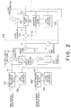
- As illustrated in Fig. 2, the interference cancellation apparatus comprises first and second forward transversal filters 101 and 102 which have a plurality of first and second taps, the first and the second forward transversal filters 101 and 102 filtering the first and the second diversity reception signals 1 and 2 into first and second transversal filtered signals Sf1 and Sf2 in accordance with first and second controllable tap gains, respectively; first and second tap gain controllers 103 and 104 for controlling the first and the second controllable tap gains with reference to a first error signal ε1 and a distributed signal distributed in each one of the first and the second taps in accordance with a predetermined adaptive algorithm, such as minimum mean square error (MMSE) algorithm; a backward transversal filter 105 which has a plurality of third taps and which filters a decision signal Sd into a third transversal filtered signal Sb in accordance with third controllable tap gains; third tap gain controller 106 for controlling the third controllable tap gains with reference to the first error signal 1 and a third distributed signal distributed in each of the third taps in accordance with the predetermined adaptive algorithm; a decision unit 107 for detecting a level of the equalized signal to decide a decision level for the equalized signal and to produce a decision signal Sd representative of the decision level to supply the decision signal Sd to the backward transversal filter 105; a first error producing unit, such as a subtractor (hereinunder called a first subtractor) 109 for producing the first error signal ε1 indicative of a difference between the subtracted signal Sr and the decision signal Sd, the first error signal ε1 being supplied to the first, the second, and the third tap gain controllers 103, 104, and 106; a second subtractor 110 for subtracting the third transversal filtered signal Sb from the combined signal Sp to supply the subtracted signal Sr to the decision unit 107 and the first subtractor 109; and a diversity combining section 158 for combining the first and the second transversal filtered signals Sf1 and Sf2 to produce a combined signal Sp.
- The diversity combining section 158 comprises an adder 108 for calculating a total sum of a first complex multiplied signal Sc1 and a second complex multiplied signal Sc2 to produce a total sum signal Sp representative of the total sum; first and second complex multipliers 112 and 113 for complexly multiplying the first and the second transversal filtered signals Sf1 and Sf2 by the first and the second correlated values α and β to produce first and second complex multiplied signals Sc1 and Sc2, respectively; first and second correlators 114 and 115 for correlating the first and the second transversal filtered signals Sf1 and Sf2 with a second error signal ε2 in each of the first and the second diversity routes to produce first and second correlation signals indicative of the first and the second correlated values α and β, respectively; and a second error producing unit, such as a subtractor (hereinunder called a third subtractor) 111 for producing the second error signal ε2 indicative of a difference between the total sum signal Sp and the decision signal Sd, the second error signal ε2 being supplied to the first and the second correlators 114 and 115, respectively.
- In this preferred embodiment, the above-mentioned equalized signal is a multilevel signal having a plurality of levels greater than two. The decision unit 107 detects which one of the levels the multilevel signal has as a decision level to produce a decision signal representative of the decision level.
- The first and the second forward transversal filters 101 and 102 are connected to respective analog to digital (A/D) converters, demodulators, and the like corresponding to respective diversity routes, although they are not shown in Fig. 2.
- Description will hereinunder proceed to an operation of the interference cancellation apparatus illustrated in Fig. 2.
- Supplied with the first and the second diversity reception signals 1 and 2, the first and the second forward transversal filters 101 and 102 produces the first and the second transversal filtered signals Sf1 and Sf2 which are deprived of each pre-cursor distortion thereby, respectively. The first and the second transversal filtered signals Sf1 and Sf2 are diversity combined by the diversity combining section 158 to produce a diversity combined signal Sp. The backward transversal filter 105 produces a third transversal filtered signal Sb which is deprived of its post-cursor distortion thereby in response to a decision signal Sd from the decision unit 107. From the diversity combined signal Sp, the third transversal filtered signal Sb is subtracted by the second subtractor 110 to produce the subtracted signal Sr. In response to the subtracted signal Sr, the decision unit 107 produces the decision signal Sd and supplies the decision signal Sd to the backward transversal filter 105 as an input signal. The first subtractor 109 calculates a difference between input and output signals of the decision unit 107, namely, the difference between the subtracted signal Sr and the decision signal Sd, to produce the first error signal ε1. In response to the first error signal ε1' the first and the second tap gain controllers 103 and 104 adjust each tap factor of the first and the second transversal filtered signals Sf1 and Sf2. The third tap gain controller 106 adjusts a tap factor of the third transversal filtered signal Sb in response to the first error signal ε1. Supplied with the first and the second transversal filtered signals Sf1 and Sf2 through each diversity route, the first and the second complex multipliers 112 and 113 carry out each complex multiply to produce first and second complex multiplied signals Sc1 and Sc2. The third subtractors 111 calculates a difference between the diversity combined signal Sp and the decision signal Sd to produce the second error signal ε2. The first and the second correlators 114 and 115 correlate the second error signal ε2 and the first and the second transversal filtered signals Sf1 and Sf2 through each diversity route to produce first and second correlation signals indicative of the first and the second correlated values α and β. The first and the second correlation signals are supplied to the first and the second complex multipliers 112 and 113 through each diversity route. The first and the second complex multipliers 112 and 113 carry out each complex multiply between the first and the second correlated values α and β and the first and the second transversal filtered signals Sf1 and Sf2 to produce the first and the second complex multiplied signals Sc1 and Sc2.
- Referring to Fig. 3, description will proceed to an operation of the interference cancellation apparatus illustrated in Fig. 2.
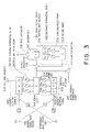
- In Fig. 3, illustrated are desired signal wave source 201 having a sampling value Sn, an interference wave source 202 having a sampling value Jn, an impulse response h1 in the transmission system responsive to the first diversity reception signal 1 at the sampling value Sn, an impulse response h2 in the transmission system responsive to the second diversity reception signal 2 at the sampling value Sn, an impulse response g1 in the transmission system responsive to the first diversity reception signal 1 at the sampling value Jn, an impulse response g2 in the transmission system responsive to the second diversity reception signal 2 at the sampling value Jn, threefold shift registers 211 and 212 each of which has T/2 interval (T: symbolic cycle), first and second multiplier groups 213 and 214 each of which consists of three multipliers, a twofold shift register 215 which has T interval, a third multiplier group 216 which consists of two multipliers, first and second adders 217 and 218, a decision unit 107, first, second, and third subtractors 109, 110, and 111. Besides, first, second, and third tap gain controllers 103, 104, and 106 are present, like in Fig. 2, although they are not shown in Fig. 3.
- Herein, it is assumed that tap factor vectors produced by the first and the second tap gain controllers 103 and 104 are depicted by C' and W', respectively.
- The first diversity reception signal 1 is defined as a first input signal r1 in Fig. 2. The r1 is multiplied with the tap factor vector C' by the convolution processing on the first forward transversal filter 101. As a result, the first transversal filtered signal Sf1 comes to be representative of r1*C'. The first transversal filtered signal Sf1 is then multiplied with the tap factor α on the first complex multiplier 112. Consequently, the first complex multiplied signal Sc1 comes to be representative of r1*αC'. On the other hand, the second diversity reception signal 2 is defined as a second input signal r2 in Fig. 2. The r2 is multiplied with the tap factor vector W' by the convolution processing on the second forward transversal filter 102. As a result, the second transversal filtered signal Sf2 comes to be representative of r2*W'. The second transversal filtered signal Sf2 is then multiplied with the tap factor β on the second complex multiplier 113 Consequently, the second complex multiplied signal Sc2 comes to be representative of r2*βW'. This means that the first and the second complex multipliers 112 and 113 can be omitted, provided that the tap factor vectors C' and W' are multiplied with the tap factors α and β, respectively.
- With this block diagram illustrated in Fig. 3, the following equations (2) and (3) are concluded.
- In Fig. 3, it is assumed that the desired wave signals 201(Sn) and 202(Jn) are broad-band modulated signals independent from each other, and that mutual correlation between symbols which are spaced from each other by more than one symbol is null. It is also assumed that Rayleigh fadings which are independent from each other are added to the impulse responses h1, h2, g1, and g2.
- In the interim, according to the above-mentioned conventional interference cancellation apparatus, i.e., Monsen's system, all tap factors of the DFE illustrated in Fig. 3 are controlled so that the means square error of the first error signal ε1 may be minimized. In such a case, a normal (wiener hopf) equalizations in which each tap factor is an unknown quantity are represented by the following equations (4), (5), (6), (7), and (8).where T represents transposition while * represents complex conjugate, and where I represents a unit matrix of 2 x 2.

 where h1 n represents a sampling value of the impulse response h1 (1 = 1, 2) at the time n.


- In the above-depicted equation (4), C, W, D represent tap factor vectors of the first and the second forward transversal filters 101 and 102, and the backward transversal filter 105, respectively. Each of C, W, D is represented by the following equation (9). On the other hand, h1 and h2 represent sampling value vectors of impulse responses h1 and h2, respectively. Each of h1 and h2 is represented by the following equation (10).
- In the above-depicted equation (4), the left-side of the normal equation is a correlated matrix of the Monsen's DFE. The correlated matrix of the Monsen's DFE is 8 x 8 in size, when applied to the system illustrated in Fig. 3. When the tap gain control is carried out in accordance with a maximum dividing method or the LMS algorithm, a performance function ξ at the time n based on mean square value of the first error signal is represented by the following equation (11).where ξmin represents a critical minimum value of the performance function, ▵0 represents an error vector between an initial value and an ideal solution concerning all the taps, qi represents an intrinsic vector concerning the tap of i turn, λi represents an eigenvalue in the correlated matrix of 8 x 8, and µ represents a tap adjusting factor in the LMS algorithm. As clearly understood from the equation (10), the correlated matrix becomes larger in size, as the degrees of the diversity routes or numbers of the filter taps are increased. Consequently, the convergence time until mean square error is minimized becomes longer. Particularly, the convergence time is deteriorated, when the eigenvalue λi becomes uneven.

- On the contrary, according to the preferred embodiment of the present invention, there is introduced the second error signal 2 produced by the third subtractor 111, as illustrated in Fig. 2. Consequently, there is introduced a secondary MMSE correlated loop which comprises the first and the second correlators 114 and 115, and the first and the second complex multipliers 112 and 113 in addition to the primary MMSE correlated loop. In other words, tap factors α and β multiplied by the first and the second complex multipliers 112 and 113 are sequentially renewed so that mean square value of the second error signal ε2 may be minimized. The secondary MMSE correlated loop is equal to an LMS correlated loop which is often used in an adaptive array. The secondary MMSE correlated loop is similar in operation to a nulling in an antenna pattern against undesired interfering and disturbing waves. Namely, in the secondary MMSE correlated loop, the tap factors α and β are controlled so that interfering waves in diversity routes may be cancelled each other at a reciprocal condition. In particular, the LMS array provides a fast convergence characteristic under such severe circumstances that desired to undesired signals ratio (D/U) comes to be negative. Further, in the presence of interfering and disturbing waves as well as multipath distortion, the secondary MMSE correlated loop responses more sensitively to the interfering and disturbing waves than to the multipath distortion. The reason is that the first and the second complex multipliers 112 and 113 are not transversal filters and so that operations of the first and the second complex multipliers 112 and 113 are restricted to a control of amplitudes and phases of the diversity input signals. In other words, the first and the second complex multipliers 112 and 113 are not capable of such a transversal filtering adaptive equalization. The first and the second complex multipliers 112 and 113 are absorbed in an anti-phase combination of the interfering and disturbing waves.
- Therefore, in the primary MMSE correlated loop with the first error signal ε1, there is carried out an adjustment of the tap factors of the first and the second forward transversal filters 101 and 102, and the backward transversal filter 105 so that multipath distortion due to variable elements h1 and g2 in the propagation paths may be removed. On the other hand, in the secondary MMSE correlated loop with the second error signal ε2, there is carried out an anti-phase cancellation of received interfering waves which is due to variable elements h2 and g1 in the propagation paths. Thus, the first MMSE control system is for use in the adaptive equalization while the second MMSE control system is for use in the interference cancellation. By assigning each part to the first and the second MMSE control systems, respectively, the adaptive equalization and the interference cancellation can be parallely processed at the same time. Consequently, both the adaptive equalization and the interference cancellation can be carried out at a high speed in the interference cancellation apparatus of the present invention, as compared with the conventional one.
- Such an operation of the interference cancellation apparatus of the present invention will be described more in detail.
- Generally, when a system has a plurality of control loops, a conflicting problem between the control loops is sometimes caused to happen. In order to solve this problem, the difference of response speed (time constant) should be made between the control loops. For example, the interference cancellation apparatus may be subjected to an environment in which the above-mentioned interfering waves are more fastly variable than the multipath waves. When the interference cancellation apparatus is subjected to such an environment, the response speed of the second MMSE control system should be predetermined to be larger than that of the first MMSE control system. Namely, the adjusting factor of the second MMSE control system should be made larger than that of the first MMSE control system, with respect to algorithms, such as the aforesaid LMS algorithm, for adjusting the tap factors. Thereby, it becomes possible that cancellation of the interfering waves is set up faster than the adaptive equalization and that the control of the adaptive equalization is converged after the cancellation of the interfering waves is finished. In this event, it becomes sufficient that the above-mentioned tap factors C' and W' are converged in a solution for the removal of the multipath distortion. In other words, it becomes possible that the correlated factors gl n gm* n-k due to the interfering waves are deleted from the above-depicted correlated matrixes in the equations (5) and (6). This means that the electric power of the interfering waves can be deleted from the electric power in the correlated matrix Rlm and so that an eigenvalue corresponding to the electric power in the correlated matrix Rlm becomes small.
- A component indicating such electric power in a correlated matrix is generally called a "trace". The "trace" is defined by the equation (12).

- As clearly understood from the above equation (12), reception power is reduced, as the eigenvalue becomes small.
- On the other hand, an MMSE control system with an LMS algorithm must comply with the following inequality (13) so as to be converged.
- In a case that a value of the above-mentioned adjusting factors exceeds the right part, (2/tr[R]), in the above inequality (13), the MMSE control is not converged but diverged. The reason is physically explained as follows.
- When the eigenvalue in the correlated matrix Rlm becomes large due to large electric power of the interfering waves, a value of the right part, (2/tr[R]) in the inequality (13) becomes small. Under such circumstances, a value of the adjusting factor µ must be kept small so that the MMSE control system may comply with the inequality (13) to be converged. However, the adaptive equalization becomes slow, when the adjusting factor µ is kept small. As a result, a convergence performance of the MMSE control system is deteriorated.
- Since the interfering waves are cancelled by the second MMSE control loop in the preferred embodiment of the present invention, it is possible that the eigenvalue is decreased by the quantity of the electric power of the interfering waves. Consequently, it is possible that the value of the right part, (2/tr[R]) in the inequality (13) becomes large. It is therefore not necessary that the adjusting factor µ in the first MMSE control system is made too small. Accordingly, the convergence performance of the first MMSE control system is not so deteriorated.
- As explained above, the adaptive equalization and the interference cancellation are processed in parallel by the first and the second MMSE control systems, so that the control of the adaptive equalization and the interference cancellation can be converged at a high speed. As a result, an excellent performance of both the adaptive equalization and the interference cancellation is achieved with respect not only to interferring waves which are variable faster than those of multipath fading but also to interfering waves by which the aforesaid D/U ratio becomes negative.
- While this invention has thus far been described in conjunction with a preferred embodiment thereof, it will readily be possible for those skilled in the art to put this invention into practice in various other manners. For example, the equalized signal may be a binary signal specified by a binary level. In this case, the decision unit 107 detects whether or not the binary level of the equalized signal exceeds a predetermined threshold level to decide a detected binary level for the equalized signal and to produce a decision signal representative of the judged binary level.
Claims (5)
- An interference cancellation apparatus for use in combination with a diversity receiving system, said apparatus being supplied with first and second diversity reception signals (1 and 2) and being operable as a decision feedback equalizer to produce an equalized signal, said apparatus comprising:first and second transversal filter means (101 and 102) for filtering said first and said second diversity reception signals (1 and 2) into first and second transversal filtered signals (Sf1 and Sf2) in accordance with first and second controllable tap gains, respectively;first and second control means (103 and 104) for controlling said first and said second controllable tap gains with reference to a first error signal (∈1) in accordance with a predetermined adaptive algorithm;third transversal filter means (105) for filtering a decision signal (Sd) into a third transversal filtered signal (Sb) in accordance with third controllable tap gains;third control means (106) for controlling said third controllable tap gains with reference to said first error signal (∈1) in accordance with said predetermined adaptive algorithm;decision means (107) for detecting a level of said equalized signal as a decision level to produce a decision signal (Sd) representative of said decision level and to supply said decision signal (Sd) to said third transversal filter means (105);first subtractor means (109) for producing said first error signal (∈1) indicative of a difference between a subtracted signal (Sr) and said decision signal (Sd), said first error signal (∈1) being supplied to said first, said second, and said third control means (103, 104 and 106);diversity combining means (158) for combining said first and said second transversal filtered signals (Sf1) and (Sf2) to produce a combined signal (Sp) and;second subtractor means (110) for subtracting said third transversal filtered signal (Sb) from said combined signal (Sp) to supply said subtracted signal (Sr) to said decision means (107) and said first subtractor means (109);said first and said second transversal filter means (101 and 102), first and second control means (103 and 104), third transversal filter means (105), third control means (106), decision means (107), first subtractor means (109), and second subtractor means (110) being operable as a first control loop for controlling said first and said second controllable tap gains and said third controllable tap gains with reference to said first error signal (∈1); characterised in that:said diversity combining means (158) is operable as a second control loop and comprisesadder means (108) for calculating a total sum of a first complex multiplied signal (Sc1) and a second complex multiplied signal (Sc2) to produce a total sum signal as said combined signal (Sp) representative of said total sum;first and second complex multiplying means (112 and 113) for complexly multiplying said first and said second transversal filtered signals (Sf1 and Sf2) by first and second correlated values α and β to produce said first and said second complex multiplied signals (Sc1 and Sc2), respectively;first and second correlation means (114 and 115) for correlating said first and said second transversal filtered signals (Sf1 and Sf2) with a second error signal (∈2) in each of first and second diversity routes to produce first and second correlation signals indicative of said first and said second correlated values α and β, respectively; andthird subtractor means (111) for producing said second error signal (∈2) indicative of a difference between said total sum signal (Sp) and said decision signal (Sd), said second error signal (∈2) being supplied to said first and said second correlation means (114 and 115), respectively.
- An interference cancellation apparatus as claimed in Claim 1, characterised in that said predetermined adaptive algorithm is a minimum mean square error algorithm, said second control loop being operated in accordance with an additional predetermined adaptive algorithm of the minimum mean square error algorithm.
- Apparatus as claimed in any preceding claim, characterised in that said diversity receiving system has first and second diversity routes, said first and second diversity reception signals (1) and (2) corresponding to said first and said second diversity routes,said first and second transversal filter means (101 and 102) having a plurality of first and second taps,said first and second control means (103 and 104) controlling said first and said second controllable tap gains with reference to said first error signal (∈1) and further with reference to a distributed signal distributed in each one of said first and said second taps in accordance with a predetermined adaptive algorithm;said third transversal filter means (105) having a plurality of third taps, andsaid third control means (106) controlling said third controllable tap gains with reference to said first error signal (∈1) and further with reference to a third distributed signal distributed in each of said third taps in accordance with said predetermined adaptive algorithm.
- An interference cancellation apparatus as claimed in any preceding claim, characterised in that said equalized signal is a binary signal specified by a binary level, said decision means detecting whether or not the binary level of said equalized signal exceeds a predetermined threshold level to decide a detected binary level for said equalized signal and to produce a decision signal representative of said detected binary level.
- An interference cancellation apparatus as claimed in any of claims 1 to 3, characterised in that said equalized signal is a multilevel signal having a plurality of levels greater than two, said decision means detecting one of said levels of said multilevel signal as a decision level to produce a decision signal representative of said decision level.
Applications Claiming Priority (3)
| Application Number | Priority Date | Filing Date | Title |
|---|---|---|---|
| JP5155439A JP2885612B2 (en) | 1993-06-25 | 1993-06-25 | Interference wave canceller |
| JP155439/93 | 1993-06-25 | ||
| JP15543993 | 1993-06-25 |
Publications (2)
| Publication Number | Publication Date |
|---|---|
| EP0631399A1 EP0631399A1 (en) | 1994-12-28 |
| EP0631399B1 true EP0631399B1 (en) | 2002-03-13 |
Family
ID=15606063
Family Applications (1)
| Application Number | Title | Priority Date | Filing Date |
|---|---|---|---|
| EP94304600A Expired - Lifetime EP0631399B1 (en) | 1993-06-25 | 1994-06-24 | Method and apparatus for interference cancellation and adaptive equalisation in diversity reception |
Country Status (3)
| Country | Link |
|---|---|
| US (1) | US5524125A (en) |
| EP (1) | EP0631399B1 (en) |
| JP (1) | JP2885612B2 (en) |
Cited By (5)
| Publication number | Priority date | Publication date | Assignee | Title |
|---|---|---|---|---|
| EP2015468A1 (en) * | 2007-07-10 | 2009-01-14 | SIAE Microelettronica S.p.A. | Baseband combiner for digital radio links |
| US7720443B2 (en) | 2003-06-02 | 2010-05-18 | Kyocera Wireless Corp. | System and method for filtering time division multiple access telephone communications |
| US7746292B2 (en) | 2001-04-11 | 2010-06-29 | Kyocera Wireless Corp. | Reconfigurable radiation desensitivity bracket systems and methods |
| US7916806B2 (en) | 1997-09-16 | 2011-03-29 | At&T Mobility Ii Llc | Transmitter diversity technique for wireless communications |
| US8351545B2 (en) | 1997-10-31 | 2013-01-08 | At&T Mobility Ii Llc | Low complexity maximum likelihood detection of concatenated space codes for wireless applications |
Families Citing this family (45)
| Publication number | Priority date | Publication date | Assignee | Title |
|---|---|---|---|---|
| DE4434723C1 (en) * | 1994-09-28 | 1995-06-14 | Siemens Ag | Adaptive network for digital transmission system |
| JP3325735B2 (en) * | 1995-01-31 | 2002-09-17 | 松下電器産業株式会社 | Data receiving device |
| JP3287971B2 (en) * | 1995-01-31 | 2002-06-04 | 松下電器産業株式会社 | Data receiving device |
| JP3270289B2 (en) * | 1995-03-15 | 2002-04-02 | 日本電気株式会社 | Decision feedback equalizer |
| JPH08315511A (en) * | 1995-05-18 | 1996-11-29 | Fujitsu Ltd | Judging feedback equalizer and two input judgement slice setting method |
| EP0813301A1 (en) * | 1996-06-10 | 1997-12-17 | TOSHIBA Electronics Europe GmbH | Adaptive digital filter |
| FR2750270B1 (en) * | 1996-06-21 | 1998-08-07 | Alcatel Telspace | EQUALIZER-COMBINER FOR DIVERSITY RECEIVER, RECEIVER INCORPORATING SUCH AN EQUALIZER-COMBINER, AND METHOD FOR RECEIVING DIVERSITY THEREOF |
| US6067319A (en) * | 1996-09-04 | 2000-05-23 | Integrated Device Technology, Inc. | Method for equalization of a quadrature amplitude modulated signal |
| DE69731455T2 (en) * | 1996-09-18 | 2005-12-15 | Koninklijke Philips Electronics N.V. | INTERFERENCE DETECTION CIRCUIT WITH DISCRIMINATION BY AMPLITUDE FREQUENCY DOMAIN DEFINITION |
| KR100226698B1 (en) * | 1996-12-28 | 1999-10-15 | 전주범 | Channel equalizer for use in ofdm receiving system |
| JP2980053B2 (en) * | 1997-03-28 | 1999-11-22 | 日本電気株式会社 | Interference wave canceller |
| US6075823A (en) * | 1997-04-09 | 2000-06-13 | Nec Corporation | Apparatus and method of achieving improved diversity reception in a digital radio communications system |
| US5901343A (en) * | 1997-05-09 | 1999-05-04 | Lockheed Martin Corporation | Adaptive cross polarization Interference canceler for use at intermediate frequencies |
| US6101228A (en) * | 1997-05-22 | 2000-08-08 | Conexant Systems, Inc. | Receiver of wideband digital signal in the presence of a narrow band interfering signal |
| CA2248345C (en) * | 1997-06-03 | 2001-08-21 | Ntt Mobile Communications Network Inc. | Adaptive array transmitter-receiver |
| US6144697A (en) * | 1998-02-02 | 2000-11-07 | Purdue Research Foundation | Equalization techniques to reduce intersymbol interference |
| US6327302B1 (en) * | 1998-08-28 | 2001-12-04 | Ericsson Inc. | Fast adaptive equalizer for wireless communication systems |
| US6320919B1 (en) * | 1998-11-30 | 2001-11-20 | Ericsson Inc. | Adaptive channel characterization using decoded symbols |
| JP2002539666A (en) * | 1999-03-10 | 2002-11-19 | ノキア モービル フォーンズ リミティド | Unsupervised adaptive chip separation filter for CDMA terminals |
| JP2001203619A (en) | 2000-01-19 | 2001-07-27 | Matsushita Electric Ind Co Ltd | Wireless base station device and wireless communication method |
| JP4581288B2 (en) * | 2000-05-09 | 2010-11-17 | パナソニック株式会社 | Demodulator |
| US7116730B2 (en) * | 2000-05-09 | 2006-10-03 | Matsushita Electric Industrial Co., Ltd. | Demodulation apparatus |
| AU2001264906A1 (en) * | 2000-05-22 | 2001-12-03 | Sarnoff Corporation | Method and apparatus for reducing multipath distortion in a wireless lan system |
| US20020106040A1 (en) * | 2001-02-02 | 2002-08-08 | Sarnoff Corporation | Method and apparatus for reducing multipath distortion in a wireless ian system |
| US6480151B2 (en) | 2000-12-29 | 2002-11-12 | Lockheed Martin Corporation | GPS receiver interference nuller with no satellite signal distortion |
| US6819911B2 (en) | 2001-04-02 | 2004-11-16 | General Dynamics Decision Systems, Inc. | Active interference suppressor utilizing recombinant transmultiplexing |
| US6990137B2 (en) * | 2001-05-17 | 2006-01-24 | Qualcomm, Incorporated | System and method for received signal prediction in wireless communications systems |
| US7170924B2 (en) | 2001-05-17 | 2007-01-30 | Qualcomm, Inc. | System and method for adjusting combiner weights using an adaptive algorithm in wireless communications system |
| US7133477B2 (en) | 2002-01-02 | 2006-11-07 | Intel Corporation | Robust low complexity multi-antenna adaptive minimum mean square error equalizer |
| US6993311B2 (en) * | 2002-02-20 | 2006-01-31 | Freescale Semiconductor, Inc. | Radio receiver having an adaptive equalizer and method therefor |
| AU2003273829A1 (en) * | 2002-06-11 | 2003-12-22 | Worcester Polytechnic Institute | Reconfigurable geolocation system |
| US6697424B1 (en) * | 2003-05-06 | 2004-02-24 | Industrial Technology Research Institute | Fast convergent pipelined adaptive decision feedback equalizer using post-cursor processing filter |
| JP4213023B2 (en) * | 2003-05-29 | 2009-01-21 | 富士通株式会社 | Adaptive control apparatus and adaptive control method |
| US7369607B2 (en) * | 2004-02-26 | 2008-05-06 | 2Wire, Inc. | Multicarrier communication using a time domain equalizing filter |
| CA2582957C (en) * | 2004-10-11 | 2013-09-03 | 2Wire Inc. | Periodic impulse noise mitigation in a dsl system |
| US7953163B2 (en) * | 2004-11-30 | 2011-05-31 | Broadcom Corporation | Block linear equalization in a multicarrier communication system |
| US7852950B2 (en) * | 2005-02-25 | 2010-12-14 | Broadcom Corporation | Methods and apparatuses for canceling correlated noise in a multi-carrier communication system |
| US9374257B2 (en) * | 2005-03-18 | 2016-06-21 | Broadcom Corporation | Methods and apparatuses of measuring impulse noise parameters in multi-carrier communication systems |
| JP4693462B2 (en) * | 2005-03-31 | 2011-06-01 | 富士通テン株式会社 | Diversity receiving apparatus and method |
| US7813439B2 (en) * | 2006-02-06 | 2010-10-12 | Broadcom Corporation | Various methods and apparatuses for impulse noise detection |
| JP5353878B2 (en) * | 2008-03-11 | 2013-11-27 | 日本電気株式会社 | Waveform equalization circuit and waveform equalization method |
| US8605837B2 (en) * | 2008-10-10 | 2013-12-10 | Broadcom Corporation | Adaptive frequency-domain reference noise canceller for multicarrier communications systems |
| IT1393478B1 (en) * | 2009-04-02 | 2012-04-27 | Siae Microelettronica Spa | PROTECTION SYSTEM FOR DIGITAL RADIO BRIDGES ADAPTIVE MODULATION OPERATING IN DIVERSITY |
| PL226101B1 (en) * | 2015-02-10 | 2017-06-30 | Sławomir Szechniuk | Method for reduction of interference and noise in the circuits with two signal lines and the phrase filter |
| CN110146848B (en) * | 2019-05-22 | 2023-06-23 | 西安电子科技大学 | Frequency modulation continuous wave radar self-interference elimination method based on fractional order least mean square |
Family Cites Families (5)
| Publication number | Priority date | Publication date | Assignee | Title |
|---|---|---|---|---|
| JPS5927133B2 (en) * | 1979-02-21 | 1984-07-03 | 日本電気株式会社 | adaptive receiver |
| US4281411A (en) * | 1979-06-25 | 1981-07-28 | Signatron, Inc. | High speed digital communication receiver |
| JP2503715B2 (en) * | 1990-03-30 | 1996-06-05 | 日本電気株式会社 | Adaptive receiver |
| JP2982504B2 (en) * | 1992-07-31 | 1999-11-22 | 日本電気株式会社 | Adaptive receiver |
| JP2780576B2 (en) * | 1992-08-05 | 1998-07-30 | 日本電気株式会社 | Interference wave canceller |
-
1993
- 1993-06-25 JP JP5155439A patent/JP2885612B2/en not_active Expired - Fee Related
-
1994
- 1994-06-24 EP EP94304600A patent/EP0631399B1/en not_active Expired - Lifetime
- 1994-06-27 US US08/265,754 patent/US5524125A/en not_active Expired - Fee Related
Cited By (11)
| Publication number | Priority date | Publication date | Assignee | Title |
|---|---|---|---|---|
| US7916806B2 (en) | 1997-09-16 | 2011-03-29 | At&T Mobility Ii Llc | Transmitter diversity technique for wireless communications |
| US8355475B2 (en) | 1997-09-16 | 2013-01-15 | At&T Mobility Ii Llc | Diversity technique for wireless communications |
| US9203499B2 (en) | 1997-09-16 | 2015-12-01 | At&T Mobility Ii Llc | Transmitter diversity technique for wireless communications |
| US8351545B2 (en) | 1997-10-31 | 2013-01-08 | At&T Mobility Ii Llc | Low complexity maximum likelihood detection of concatenated space codes for wireless applications |
| US8731107B2 (en) | 1997-10-31 | 2014-05-20 | At&T Mobility Ii Llc | Low complexity maximum likelihood detection of concatenated space codes for wireless applications |
| US9065516B2 (en) | 1997-10-31 | 2015-06-23 | At&T Mobility Ii, Llc | Low complexity maximum likelihood detection of concatenated space codes for wireless applications |
| US7746292B2 (en) | 2001-04-11 | 2010-06-29 | Kyocera Wireless Corp. | Reconfigurable radiation desensitivity bracket systems and methods |
| US8237620B2 (en) | 2001-04-11 | 2012-08-07 | Kyocera Corporation | Reconfigurable radiation densensitivity bracket systems and methods |
| US7720443B2 (en) | 2003-06-02 | 2010-05-18 | Kyocera Wireless Corp. | System and method for filtering time division multiple access telephone communications |
| US8478205B2 (en) | 2003-06-02 | 2013-07-02 | Kyocera Corporation | System and method for filtering time division multiple access telephone communications |
| EP2015468A1 (en) * | 2007-07-10 | 2009-01-14 | SIAE Microelettronica S.p.A. | Baseband combiner for digital radio links |
Also Published As
| Publication number | Publication date |
|---|---|
| JPH0715381A (en) | 1995-01-17 |
| US5524125A (en) | 1996-06-04 |
| JP2885612B2 (en) | 1999-04-26 |
| EP0631399A1 (en) | 1994-12-28 |
Similar Documents
| Publication | Publication Date | Title |
|---|---|---|
| EP0631399B1 (en) | Method and apparatus for interference cancellation and adaptive equalisation in diversity reception | |
| US5119401A (en) | Decision feedback equalizer including forward part whose signal reference point is shiftable depending on channel response | |
| EP0720334B1 (en) | Decision feedback equalizer for cancelling short- and long-multipath components using correspondingly delayed decision symbols | |
| EP0680154B1 (en) | Interference cancellation using power-inversion adaptive array and LMS adaptive equalizer | |
| US6144697A (en) | Equalization techniques to reduce intersymbol interference | |
| US4328585A (en) | Fast adapting fading channel equalizer | |
| Hsu | Square root Kalman filtering for high-speed data received over fading dispersive HF channels | |
| EP0684706B1 (en) | Replica producing adaptive demodulating method and demodulator using the same | |
| JP2669393B2 (en) | Interference wave canceller | |
| EP1624634A2 (en) | Method and apparatus for receiving signals in MIMO system | |
| EP1413106B1 (en) | Software definable block adaptive decision feedback equalizer | |
| KR19990076683A (en) | Method and apparatus for reducing intersymbol interference using array processing of diversity signals | |
| US20050232347A1 (en) | Apparatus and method for noise enhancement reduction in an adaptive equalizer | |
| EP0757456B1 (en) | Diversity receivers | |
| EP1530300B1 (en) | Method and apparatus for equalisation in a receiver of a cdma communications system | |
| EP1563657B1 (en) | Transform-domain sample-by-sample decision feedback equalizer | |
| JP2503715B2 (en) | Adaptive receiver | |
| US20040101075A1 (en) | Method and apparatus for performing channel equalization in communication systems | |
| US6650702B1 (en) | Blind initialization of decision feedback equalizer using an antenna array | |
| JPH03284014A (en) | Decision feedback type equalizer | |
| Schirtzinger et al. | Designing adaptive equalizers based on the constant modulus error criterion | |
| US20070260659A1 (en) | Computing Filter Coefficients for an Equalizer in a Communication Receiver | |
| JP2745900B2 (en) | Interference wave canceller | |
| Tidestav | Designing equalizers based on explicit channel models of DS-CDMA systems | |
| JPH07226704A (en) | Adaptive equalizer |
Legal Events
| Date | Code | Title | Description |
|---|---|---|---|
| PUAI | Public reference made under article 153(3) epc to a published international application that has entered the european phase |
Free format text: ORIGINAL CODE: 0009012 |
|
| AK | Designated contracting states |
Kind code of ref document: A1 Designated state(s): FR GB IT |
|
| 17P | Request for examination filed |
Effective date: 19941018 |
|
| 17Q | First examination report despatched |
Effective date: 19980310 |
|
| GRAG | Despatch of communication of intention to grant |
Free format text: ORIGINAL CODE: EPIDOS AGRA |
|
| GRAG | Despatch of communication of intention to grant |
Free format text: ORIGINAL CODE: EPIDOS AGRA |
|
| GRAG | Despatch of communication of intention to grant |
Free format text: ORIGINAL CODE: EPIDOS AGRA |
|
| GRAH | Despatch of communication of intention to grant a patent |
Free format text: ORIGINAL CODE: EPIDOS IGRA |
|
| GRAH | Despatch of communication of intention to grant a patent |
Free format text: ORIGINAL CODE: EPIDOS IGRA |
|
| REG | Reference to a national code |
Ref country code: GB Ref legal event code: IF02 |
|
| GRAA | (expected) grant |
Free format text: ORIGINAL CODE: 0009210 |
|
| AK | Designated contracting states |
Kind code of ref document: B1 Designated state(s): FR GB IT |
|
| ET | Fr: translation filed | ||
| PLBE | No opposition filed within time limit |
Free format text: ORIGINAL CODE: 0009261 |
|
| STAA | Information on the status of an ep patent application or granted ep patent |
Free format text: STATUS: NO OPPOSITION FILED WITHIN TIME LIMIT |
|
| 26N | No opposition filed |
Effective date: 20021216 |
|
| PGFP | Annual fee paid to national office [announced via postgrant information from national office to epo] |
Ref country code: FR Payment date: 20030610 Year of fee payment: 10 |
|
| PGFP | Annual fee paid to national office [announced via postgrant information from national office to epo] |
Ref country code: GB Payment date: 20030618 Year of fee payment: 10 |
|
| PG25 | Lapsed in a contracting state [announced via postgrant information from national office to epo] |
Ref country code: GB Free format text: LAPSE BECAUSE OF NON-PAYMENT OF DUE FEES Effective date: 20040624 |
|
| GBPC | Gb: european patent ceased through non-payment of renewal fee |
Effective date: 20040624 |
|
| PG25 | Lapsed in a contracting state [announced via postgrant information from national office to epo] |
Ref country code: FR Free format text: LAPSE BECAUSE OF NON-PAYMENT OF DUE FEES Effective date: 20050228 |
|
| REG | Reference to a national code |
Ref country code: FR Ref legal event code: ST |
|
| PG25 | Lapsed in a contracting state [announced via postgrant information from national office to epo] |
Ref country code: IT Free format text: LAPSE BECAUSE OF NON-PAYMENT OF DUE FEES Effective date: 20050624 |