EP0631444B1 - Time-varying image encoder - Google Patents
Time-varying image encoder Download PDFInfo
- Publication number
- EP0631444B1 EP0631444B1 EP93905614A EP93905614A EP0631444B1 EP 0631444 B1 EP0631444 B1 EP 0631444B1 EP 93905614 A EP93905614 A EP 93905614A EP 93905614 A EP93905614 A EP 93905614A EP 0631444 B1 EP0631444 B1 EP 0631444B1
- Authority
- EP
- European Patent Office
- Prior art keywords
- signal
- resolution
- low
- picture
- coding
- Prior art date
- Legal status (The legal status is an assumption and is not a legal conclusion. Google has not performed a legal analysis and makes no representation as to the accuracy of the status listed.)
- Expired - Lifetime
Links
- 238000005070 sampling Methods 0.000 claims description 116
- 238000006243 chemical reaction Methods 0.000 claims description 5
- 238000011156 evaluation Methods 0.000 claims description 3
- 230000000295 complement effect Effects 0.000 claims description 2
- 239000013598 vector Substances 0.000 description 154
- 238000010586 diagram Methods 0.000 description 37
- 238000000034 method Methods 0.000 description 24
- 230000008569 process Effects 0.000 description 12
- 230000006870 function Effects 0.000 description 8
- 230000003044 adaptive effect Effects 0.000 description 6
- 101000969688 Homo sapiens Macrophage-expressed gene 1 protein Proteins 0.000 description 5
- 102100021285 Macrophage-expressed gene 1 protein Human genes 0.000 description 5
- 230000005540 biological transmission Effects 0.000 description 5
- 230000008901 benefit Effects 0.000 description 4
- 230000002457 bidirectional effect Effects 0.000 description 4
- 238000001514 detection method Methods 0.000 description 3
- 238000012545 processing Methods 0.000 description 3
- 238000004891 communication Methods 0.000 description 2
- 230000002542 deteriorative effect Effects 0.000 description 2
- 238000001914 filtration Methods 0.000 description 2
- 230000006872 improvement Effects 0.000 description 2
- 238000012935 Averaging Methods 0.000 description 1
- 238000012986 modification Methods 0.000 description 1
- 230000004048 modification Effects 0.000 description 1
- 230000003287 optical effect Effects 0.000 description 1
- 230000011218 segmentation Effects 0.000 description 1
Images


Classifications
-
- H—ELECTRICITY
- H04—ELECTRIC COMMUNICATION TECHNIQUE
- H04N—PICTORIAL COMMUNICATION, e.g. TELEVISION
- H04N19/00—Methods or arrangements for coding, decoding, compressing or decompressing digital video signals
- H04N19/50—Methods or arrangements for coding, decoding, compressing or decompressing digital video signals using predictive coding
- H04N19/503—Methods or arrangements for coding, decoding, compressing or decompressing digital video signals using predictive coding involving temporal prediction
- H04N19/51—Motion estimation or motion compensation
- H04N19/577—Motion compensation with bidirectional frame interpolation, i.e. using B-pictures
-
- H—ELECTRICITY
- H04—ELECTRIC COMMUNICATION TECHNIQUE
- H04N—PICTORIAL COMMUNICATION, e.g. TELEVISION
- H04N19/00—Methods or arrangements for coding, decoding, compressing or decompressing digital video signals
- H04N19/10—Methods or arrangements for coding, decoding, compressing or decompressing digital video signals using adaptive coding
- H04N19/102—Methods or arrangements for coding, decoding, compressing or decompressing digital video signals using adaptive coding characterised by the element, parameter or selection affected or controlled by the adaptive coding
- H04N19/103—Selection of coding mode or of prediction mode
- H04N19/105—Selection of the reference unit for prediction within a chosen coding or prediction mode, e.g. adaptive choice of position and number of pixels used for prediction
-
- H—ELECTRICITY
- H04—ELECTRIC COMMUNICATION TECHNIQUE
- H04N—PICTORIAL COMMUNICATION, e.g. TELEVISION
- H04N19/00—Methods or arrangements for coding, decoding, compressing or decompressing digital video signals
- H04N19/10—Methods or arrangements for coding, decoding, compressing or decompressing digital video signals using adaptive coding
- H04N19/102—Methods or arrangements for coding, decoding, compressing or decompressing digital video signals using adaptive coding characterised by the element, parameter or selection affected or controlled by the adaptive coding
- H04N19/117—Filters, e.g. for pre-processing or post-processing
-
- H—ELECTRICITY
- H04—ELECTRIC COMMUNICATION TECHNIQUE
- H04N—PICTORIAL COMMUNICATION, e.g. TELEVISION
- H04N19/00—Methods or arrangements for coding, decoding, compressing or decompressing digital video signals
- H04N19/10—Methods or arrangements for coding, decoding, compressing or decompressing digital video signals using adaptive coding
- H04N19/134—Methods or arrangements for coding, decoding, compressing or decompressing digital video signals using adaptive coding characterised by the element, parameter or criterion affecting or controlling the adaptive coding
- H04N19/136—Incoming video signal characteristics or properties
- H04N19/137—Motion inside a coding unit, e.g. average field, frame or block difference
- H04N19/139—Analysis of motion vectors, e.g. their magnitude, direction, variance or reliability
-
- H—ELECTRICITY
- H04—ELECTRIC COMMUNICATION TECHNIQUE
- H04N—PICTORIAL COMMUNICATION, e.g. TELEVISION
- H04N19/00—Methods or arrangements for coding, decoding, compressing or decompressing digital video signals
- H04N19/10—Methods or arrangements for coding, decoding, compressing or decompressing digital video signals using adaptive coding
- H04N19/134—Methods or arrangements for coding, decoding, compressing or decompressing digital video signals using adaptive coding characterised by the element, parameter or criterion affecting or controlling the adaptive coding
- H04N19/154—Measured or subjectively estimated visual quality after decoding, e.g. measurement of distortion
-
- H—ELECTRICITY
- H04—ELECTRIC COMMUNICATION TECHNIQUE
- H04N—PICTORIAL COMMUNICATION, e.g. TELEVISION
- H04N19/00—Methods or arrangements for coding, decoding, compressing or decompressing digital video signals
- H04N19/10—Methods or arrangements for coding, decoding, compressing or decompressing digital video signals using adaptive coding
- H04N19/134—Methods or arrangements for coding, decoding, compressing or decompressing digital video signals using adaptive coding characterised by the element, parameter or criterion affecting or controlling the adaptive coding
- H04N19/157—Assigned coding mode, i.e. the coding mode being predefined or preselected to be further used for selection of another element or parameter
- H04N19/16—Assigned coding mode, i.e. the coding mode being predefined or preselected to be further used for selection of another element or parameter for a given display mode, e.g. for interlaced or progressive display mode
-
- H—ELECTRICITY
- H04—ELECTRIC COMMUNICATION TECHNIQUE
- H04N—PICTORIAL COMMUNICATION, e.g. TELEVISION
- H04N19/00—Methods or arrangements for coding, decoding, compressing or decompressing digital video signals
- H04N19/10—Methods or arrangements for coding, decoding, compressing or decompressing digital video signals using adaptive coding
- H04N19/169—Methods or arrangements for coding, decoding, compressing or decompressing digital video signals using adaptive coding characterised by the coding unit, i.e. the structural portion or semantic portion of the video signal being the object or the subject of the adaptive coding
- H04N19/17—Methods or arrangements for coding, decoding, compressing or decompressing digital video signals using adaptive coding characterised by the coding unit, i.e. the structural portion or semantic portion of the video signal being the object or the subject of the adaptive coding the unit being an image region, e.g. an object
- H04N19/172—Methods or arrangements for coding, decoding, compressing or decompressing digital video signals using adaptive coding characterised by the coding unit, i.e. the structural portion or semantic portion of the video signal being the object or the subject of the adaptive coding the unit being an image region, e.g. an object the region being a picture, frame or field
-
- H—ELECTRICITY
- H04—ELECTRIC COMMUNICATION TECHNIQUE
- H04N—PICTORIAL COMMUNICATION, e.g. TELEVISION
- H04N19/00—Methods or arrangements for coding, decoding, compressing or decompressing digital video signals
- H04N19/30—Methods or arrangements for coding, decoding, compressing or decompressing digital video signals using hierarchical techniques, e.g. scalability
-
- H—ELECTRICITY
- H04—ELECTRIC COMMUNICATION TECHNIQUE
- H04N—PICTORIAL COMMUNICATION, e.g. TELEVISION
- H04N19/00—Methods or arrangements for coding, decoding, compressing or decompressing digital video signals
- H04N19/50—Methods or arrangements for coding, decoding, compressing or decompressing digital video signals using predictive coding
- H04N19/503—Methods or arrangements for coding, decoding, compressing or decompressing digital video signals using predictive coding involving temporal prediction
- H04N19/51—Motion estimation or motion compensation
-
- H—ELECTRICITY
- H04—ELECTRIC COMMUNICATION TECHNIQUE
- H04N—PICTORIAL COMMUNICATION, e.g. TELEVISION
- H04N19/00—Methods or arrangements for coding, decoding, compressing or decompressing digital video signals
- H04N19/50—Methods or arrangements for coding, decoding, compressing or decompressing digital video signals using predictive coding
- H04N19/587—Methods or arrangements for coding, decoding, compressing or decompressing digital video signals using predictive coding involving temporal sub-sampling or interpolation, e.g. decimation or subsequent interpolation of pictures in a video sequence
-
- H—ELECTRICITY
- H04—ELECTRIC COMMUNICATION TECHNIQUE
- H04N—PICTORIAL COMMUNICATION, e.g. TELEVISION
- H04N19/00—Methods or arrangements for coding, decoding, compressing or decompressing digital video signals
- H04N19/50—Methods or arrangements for coding, decoding, compressing or decompressing digital video signals using predictive coding
- H04N19/59—Methods or arrangements for coding, decoding, compressing or decompressing digital video signals using predictive coding involving spatial sub-sampling or interpolation, e.g. alteration of picture size or resolution
-
- H—ELECTRICITY
- H04—ELECTRIC COMMUNICATION TECHNIQUE
- H04N—PICTORIAL COMMUNICATION, e.g. TELEVISION
- H04N19/00—Methods or arrangements for coding, decoding, compressing or decompressing digital video signals
- H04N19/60—Methods or arrangements for coding, decoding, compressing or decompressing digital video signals using transform coding
- H04N19/61—Methods or arrangements for coding, decoding, compressing or decompressing digital video signals using transform coding in combination with predictive coding
-
- H—ELECTRICITY
- H04—ELECTRIC COMMUNICATION TECHNIQUE
- H04N—PICTORIAL COMMUNICATION, e.g. TELEVISION
- H04N19/00—Methods or arrangements for coding, decoding, compressing or decompressing digital video signals
- H04N19/60—Methods or arrangements for coding, decoding, compressing or decompressing digital video signals using transform coding
Definitions
- the present invention relates to a motion picture coding apparatus, and, more particularly, to a motion picture coding apparatus for use in a system, which transmits motion pictures over a line, such as a TV conference or a TV telephone, a system for storing motion pictures on a storage medium, such as an optical disk or a video tape, and digital television broadcasting.
- H. 261 and MPEG1 which are standard systems for motion picture coding whose targets are lower picture quality and lower bit rate.
- the supply of hardware for those standardizations has started. Therefore, one of issues is that a new standard system to achieve higher picture quality should have mutual connectability (compatibility) with those existing standard systems.
- compatibility There are two types of compatibility: forward compatibility which permits a decoder of the new system to decode a bit stream prepared by an encoder of an existing system and backward compatibility which permits a decoder of the existing system to decode a part of a bit stream prepared by an encoder of the new system.
- forward compatibility which permits a decoder of the new system to decode a bit stream prepared by an encoder of an existing system
- backward compatibility which permits a decoder of the existing system to decode a part of a bit stream prepared by an encoder of the new system.
- image picture
- MPEG1 MPEG1
- prediction using a local decoded signal by the existing system is added as an option, and this prediction is selected only when it is better than the prediction originated from a local decoded signal by the new system.
- a better one of a local decoded signal from a local decoder of the new system and a local decoded signal that is input via an up-sampling circuit from a local decoder of the existing system is selectively used as a predictive signal in a coding section. It is therefore considered that the coding efficiency will not be deteriorated by the inclusion of the latter prediction from the local decoded signal by the existing system.
- the prediction by the existing system is effective and will be selected accordingly, whereas for the P picture and B picture, the prediction originating from a local decoded signal for the coding result by the existing system is not so effective and the chance of its being selected becomes very low. It is known that one cause for this depends on the way of preparing a picture to be coded by the existing system.
- the prediction by the existing system is effective and will be selected accordingly, whereas for the P picture and B picture, the prediction originating from a local decoded signal by the existing system is not so effective and the chance of its being selected becomes very low.
- motion picture coding apparatus comprising:
- a predictive signal is attained by a weighted sum of said low-resolution predictive signal and said high-resolution predictive signal.
- the apparatus may comprise prediction-signal selecting means for selecting a predictive signal used by said first coding means from said high-resolution predictive signal and said low-resolution predictive signal under a determination criterion where prediction error power in cases when said high-resolution predictive signal and said low-resolution predictive signal are used in predictive coding in said first coding means, and an amount of additional information generated by said first coding means are considered.
- means for shifting a low-resolution local decoded signal and means for determining the shift amount based on the motion vector of the high-resolution picture signal are used.
- the use of a low-resolution local decoded signal by the existing system becomes effective as a predictive signal not only for an I picture but also for a P picture and a B picture, thus improving the entire coding efficiency.
- a predictive signal obtained by using a low-resolution local decoded signal based on the existing system is more effectively selected, by taking an amount of additional information such as motion vector information as well as a prediction error power in consideration.
- the coding efficiency can be improved by further performing predictive coding on a high-resolution prediction error signal, which has remained because sufficient matching has not been done by the motion compensation of the low-resolution by the new system alone, by using prediction error by the existing system.
- the first up-sampling means may comprise (a) intra-field interpolation-signal producing means for producing an intra-field interpolation signal consisting only of one field of a signal of the low-resolution local decoded signal, (b) intra-frame interpolation-signal producing means for producing an intra-frame interpolation signal formed of consecutive two fields of signals of the low-resolution local decoded signal, and (c) selecting means for selecting, as the output signal of the up-sampling means, that one signal among the intra-field interpolation signal, the intra-frame interpolation signal and signals obtained by weighting and adding the interpolation signals, which is adaptively determined based on at least one of the high-resolution picture signal and other information necessary for coding.
- adaptive up-sampling according to the motion of a picture can be performed by selectively using one of either the intra-field interpolation signal or intra-frame interpolation signal of the low-resolution local decoded signal, and a signal obtained by weighting and adding those signals, which is adaptively determined based on at least one of the high-resolution picture signal and the other information necessary for coding.
- the up-sampling means may, alternatively comprise (a) first and second motion-compensation up-sampling means for performing motion-compensation up-sampling on consecutive two fields of the low-resolution local decoded signal, and (b) vector computing means for computing a motion vector used in the first and second motion-compensation up-sampling means, based on at least one of a motion vector used in predictive coding of the low-resolution picture signal and a motion vector used in predictive coding of the high-resolution picture signal.
- the motion vector may be obtained by searching around the computed motion vector as a reference.
- the motion vector for motion-compensation up-sampling is determined with a high-resolution picture signal as a reference picture signal, the optimal motion vector for predictive coding of the high-resolution picture signal will be determined, thus improving the coding efficiency.
- the up-sampling of a low-resolution local decoded signal is subjected to motion-compensation up-sampling, it is not particularly necessary to send the motion vector necessary to the motion-compensation up-sampling by performing computation using the motion vector that is used in the predictive coding of the low-resolution picture signal or the predictive coding of the high-resolution picture signal.
- the searching range for the motion vector can be narrowed as compared with the case where the motion vector for motion-compensation up-sampling is directly obtained and send out. Therefore, the amount of motion vector information as well as hardware will be reduced.
- the apparatus may further comprise weighting-coefficient determining means for determining a weighting coefficient used in the weighting and adding, using at least one of (a) a motion vector used in predictive coding of the low-resolution picture signal, (b) a motion vector used in predictive coding of the high-resolution picture signal, and (c) a motion vector used in motion-compensation up-sampling when the up-sampling means performs the motion-compensation up-sampling, and (d) an amount of shift in a case of predicting a signal obtained by shifting a picture resulting from up-sampling of a low-resolution local decoded signal by an amount corresponding to motion within a field period.
- weighting-coefficient determining means for determining a weighting coefficient used in the weighting and adding, using at least one of (a) a motion vector used in predictive coding of the low-resolution picture signal, (b) a motion vector used in predictive coding of the high-resolution picture signal, and (c) a
- a picture to be coded by a new system is an interlaced picture
- a picture to be coded by the existing system is a non-interlaced picture prepared by dropping one field from the interlaced picture
- an interlaced picture is coded with frame multiplexing.
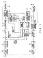
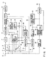
- a terminal 10 where an input picture signal is to be input is connected to a dividing circuit 101 via a field merge circuit 100.
- the field merge circuit 100 performs field merging of a field picture to treat the field picture of an input picture signal as a frame picture, and the dividing circuit 101 is provided to divide the frame picture into a plurality of blocks.
- the output of the dividing circuit 101 is connected to one input terminal of a subtracter 12 and a predictor and prediction-mode decision unit 104.
- the other input terminal of the subtracter 12 is connected to the output terminal of the predictor and prediction-mode decision unit 104.
- the output terminal of the subtracter 12 is connected to the input terminal of a discrete cosine transform (DCT) circuit 17.
- DCT discrete cosine transform
- the output terminal of the DCT circuit 17 is connected to the input terminal of a variable-length coder 19 via a quantizer 18 which quantizes DCT coefficient data from the DCT circuit 17.
- the output terminal of the variable-length coder 19 is connected to the input terminal of a buffer memory 20.
- This buffer memory 20 is connected to the quantizer and an output terminal 21.
- the output terminal of the quantizer 18 is connected to one input terminal of an adder 24 via an inverse quantizer 22 and an inverse discrete cosine transform (inverse DCT) circuit 23.
- the adder 24 adds inverse DCT data and a predictive signal together to produce a high-resolution local decoded signal.
- the other input terminal of the adder 24 is connected to the output terminal of the predictor and prediction-mode decision unit 104, and the output terminal of the adder 24 is connected to a prediction circuit 134 (Fig. 4) of the predictor and prediction-mode decision unit 104 via a frame memory 27 for storing a high-resolution local decoded signal.
- a prediction-mode decision unit 135 (Fig. 4) of the predictor and prediction-mode decision unit 104 has its prediction-mode output terminal and a motion-vector output terminal connected to the variable-length coder 19.
- the input terminal 10 is connected to the input terminal of a coding section 30 of the existing system via a field skip circuit 102, a down-sampling circuit 29 and a dividing circuit 103 in a serial manner.
- the output terminal of the coding section 30 is connected to an output terminal 32 via a buffer memory 31 and to the input terminal of a local decoder 33 of the existing system.
- the output terminal of the local decoder 33 is connected to a low-resolution prediction selector 132 (Fig. 4) of the predictor and prediction-mode decision unit 104 via an up-sampling circuit 35.
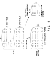
- Fig. 2 shows the relationship between to-be-coded pictures of various sizes.
- Figs. 3A and 3B show selectable candidates for low-resolution prediction in this embodiment.
- a field picture signal of an input picture signal input from the input terminal 10 is subjected to field merging in the field merge circuit 100 to be treated as a signal of a frame picture as shown in Fig. 2.
- the frame picture signal from the field merge circuit 100 is divided into a plurality of picture blocks by the dividing circuit 101 for coding.
- Image data subjected to block segmentation after merged to a frame picture is such data that data of an odd field (Odd field) and data of an even field (Even field) appear alternately line by line as indicated on the left end in Figs. 3A and 3B.
- data of 4 ⁇ 4 blocks is shown for descriptive simplification, and o indicates data of an odd field and ⁇ indicates data of an even field.
- signals for various types of inter-frame prediction (by referring a picture in the frame memory 27) from a high-resolution picture, intra-frame prediction, or prediction from a low-resolution picture (by referring a picture obtained by up-sampling a picture in the frame memory in the local decoder 33 of the existing system by the up-sampling circuit 35) considered as prediction candidates are produced, and differences between these signals and the input signal are obtained.
- a prediction mode to minimize the difference is selected based on a certain evaluation criterion. For the prediction from the high-resolution picture whose detailed description will be omitted because it is not concerned with the subject matter of this invention, but, for example, a system currently considered in MPEG2.
- the predictor and prediction-mode decision unit 104 separates the input signal to odd lines and even lines, and obtains an optimal signal (double triangle in Fig. 3B) from all available signals as a high-resolution predictive signal for each line.
- pixels at a position corresponding to the current coding block in the frame memory in the local decoder 33 of the existing system are read out, and up-sampled by the up-sampling circuit 35. Finally, those pixels are alternately merged line by line to be a predictive signal.
- a predictive signal only from a low-resolution picture is produced by up-sampling a picture in the frame memory of the existing system.
- matching is separately performed on the pixels o and ⁇ of the input picture while shifting pixels in the picture obtained by up-sampling a low-resolution picture to find the optimal amounts of shift.
- a signal merged line by line alternately with those pixels and a signal merged line by line with the predictive signal of a high-resolution picture are produced in a similar manner.
- three candidates are produced for a low-resolution predictive signal ((1) odd: low resolution, even: high resolution; (2) odd: high resolution, even: low resolution; (3) low resolution for both odd and even).
- the predictor and prediction-mode decision unit 104 selects a candidate, which optimizes the prediction error, from among those three candidates from the low-resolution predictive signal and candidates from the high-resolution predictive signal, gives the optimal candidate as a predictive signal to the subtracter 12 and sends a prediction mode to the variable-length coder 19.
- the prediction mode is subjected to variable-length coding as type information and multiplexed for each prediction unit (e.g., a macroblock for MPEG). In this embodiment, different type information are assigned to all the candidates for the predictive signal.
- Another embodiment is to indicate by 1-bit flag whether or not prediction from a low-resolution picture is to be included.
- Fig. 4 is a block diagram showing an example of the structure of the predictor and prediction-mode decision unit 104 in Fig. 1, and its operation will be described in association with the description of Figs. 3A and 3B.
- an input block is separated to lines of pixels o and ⁇ by an even/odd numbered line separator 130, an optimal predictive signal (double triangle) is obtained from a high-resolution picture for each field by a high-resolution prediction selector 131, and a motion vector corresponding to the optimal predictive signal is sent to prediction-mode decision unit 135.
- an optimal predictive signal ⁇ is obtained from a low-resolution picture for each field by the low-resolution prediction selector 132, and a motion vector corresponding to the optimal predictive signal is sent, when necessary, to prediction-mode decision unit 135.
- An even/odd numbered line merge circuit 133 executes three types of merging from a combination of the above, yielding a predictive signal corresponding to Figs. 3A and 3B, and this signal is sent to the prediction-mode decision unit 135.
- the high-resolution prediction circuit 134 prepares a high-resolution predictive signal other than the sent predictive signal (e.g., a signal corresponding to prediction that is currently under consideration in MPEG2), and it is sent together with a corresponding motion vector to the prediction-mode decision unit 135.
- the prediction-mode decision unit 135 selects a predictive signal, which minimizes the prediction error, from among all the received predictive signals, and sends it to the subtracter 12.
- the prediction-mode decision unit 135 also selects a motion vector, which minimizes the prediction error, from among all the received motion vectors, and sends it to the variable-length coder 19.
- the optimal shift amount detected for a low-resolution picture may be subjected as motion vector information to variable-length coding in the variable-length coder 19 as separate from the motion vector information of the high-resolution picture, and may be multiplexed before transmission.
- this mode may be eliminated from selective targets in this embodiment.
- the shifting may be restricted to the prediction of only the field dropped out by the field skipping.
- Fig. 5 is a diagram showing the structure of the predictor and prediction-mode decision circuit in this embodiment; same reference numerals as used in Fig. 4 are used for same portions.
- candidates for a high-resolution predictive signal are produced by the high-resolution prediction circuit 134 as in the embodiment shown in Fig. 4. They include the detection of forward and backward motion vectors. An input is separated into even and odd lines by the even/odd line separator 130, and an optimal high-resolution picture in the case where prediction is performed with a high-resolution picture for each field is selected by the high-resolution prediction selector 131.
- This embodiment differs from the above-described embodiment in the way of producing a low-resolution predictive signal, which is selected by the low-resolution prediction selector 132 and used for prediction of that field dropped out by the field skipping.
- Motion vector detection is performed and a low-resolution predictive signal is prepared using motion compensation in the above-described embodiment, whereas a low-resolution predictive signal is prepared using a motion vector which is derived by scaling the motion vector obtained for a candidate for high-resolution prediction down to that corresponding to one field time interval.
- a motion vector given as a candidate for high-resolution prediction for the prediction of an even field for example, a vector V1 in the diagram (indicated by a broken line in the diagram)
- the vector of a motion vector V1' for low-resolution prediction (indicated by a thick line in the diagram) will be obtained.
- V1' V1/n
- search is conducted in the determined search area around this motion vector to obtain an optimal motion vector again for low-resolution prediction.
- the optimal motion vector is a vector V1
- the difference between this vector V1" and the reference vector V1' ⁇ V V1" - V1'
- the candidate for the predictive signal prepared on the low-resolution side and the candidate for the predictive signal on the high-resolution side are averaged by an averaging circuit 140, and are merged by the even/odd line merge circuit 133 to be candidates for a low-resolution predictive signal. From among those candidates and the candidates from the high-resolution predictive signal, a predictive signal candidate which minimizes the prediction error is selected by the prediction-mode decision unit 135.
- the vector V1' is used on the low-resolution side when a candidate for which the vector V1, for example, in Fig. 6 is used is selected
- the vector V2' is used on the low-resolution side when a candidate for which the vector V2 is used is selected.
- forward direction forward direction
- backward direction bidirectional.
- a motion vector on the field side closer to a to-be-predicted field has only to be used.
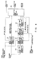
- Fig. 7 is a block diagram of a motion picture coding apparatus according to the second embodiment of this invention. This embodiment will be described with reference to the case where a picture to be coded by the new system is an interlaced picture, a picture to be coded by the existing system is a non-interlaced picture prepared by dropping one field from the interlaced picture.
- a high-resolution picture signal is input as an input picture signal 11 to a terminal 10.
- This input picture signal 11 is input to a subtracter 12 where the difference between this signal and a high-resolution predictive signal 13 is obtained, yielding a high-resolution prediction error signal 14.
- a first selector switch 15 selects one of the input picture signal 11, the high-resolution prediction error signal 14 and a low-resolution predictive signal 16 under the control of a prediction-mode decision circuit 37.
- the signal selected by the selector switch 15 is subjected to DCT coding in a DCT (Discrete Cosine Transform) circuit 17.
- DCT coefficient data obtained by the DCT circuit 17 is quantized by an quantizer 18.
- the signal quantized by the quantizer 18 is sent to two ways; one is subjected to variable-length coding in a variable-length coder 19 and is then sent via a buffer 20 to a transmission system or a storage system at a predetermined bit rate from an output terminal 21.
- the subtracter 12, DCT circuit 17, quantizer 18 and variable-length coder 19 constitute the first coding means.
- the other one of the signal quantized by the quantizer 18 and branched to two ways is sequentially subjected to opposite processes to those of the quantizer 18 and DCT circuit 17 in an inverse quantizer 22 and an inverse DCT circuit 23, and is then added to a signal selected by a second selector switch 25 in an adder 24, yielding a high-resolution local decoded signal 26.
- the inverse quantizer 22, inverse DCT circuit 23 and adder 24 constitute the first local decoding means.
- the selector switch 25 is controlled, interlocked with the selector switch 15, by the prediction-mode decision circuit 37, and selects "0" when the selector switch 15 selects the input picture signal 11, the high-resolution predictive signal 13 when the switch 15 selects the high-resolution prediction error signal 14, and selects the low-resolution predictive signal 16 when the switch 15 selects the low-resolution predictive signal 16.
- the high-resolution local decoded signal 26 output from the adder 24 is written in a frame memory 27 having a memory capacity for a plurality of frames.
- the output of the frame memory 27 is input to a predictor 28 and is used to prepare the high-resolution predictive signal 13.
- the predictor 28 detects a motion vector between the input picture signal 11, which is a high-resolution picture signal, and the high-resolution local decoded signal from the frame memory 27, and performs motion compensation inter-frame (inter-field) prediction using this motion vector to produce the high-resolution predictive signal 13 and outputs motion vector information 38.
- the predictive signal thus obtained includes three ways of prediction, namely the forward prediction, the backward prediction and the bidirectional prediction, as described in the aforementioned document, and optimal prediction among those will be selected.
- the input picture signal 11 is also input to a down-sampling circuit 29, which is means for converting a high-resolution picture signal to a low-resolution picture signal, and is down-sampled there to be converted into a low-resolution picture signal of a format, such as CIF or SIF.
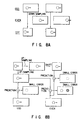
- An example of the process in the down-sampling circuit 29 is down-sampling by dropping one field off as shown in Fig. 8A.
- a low-resolution picture signal indicated by a small rectangle is prepared by dropping off an even field of a high-resolution picture signal indicated by an elongated, large rectangle and subsampling an odd field in the horizontal direction after putting it through a low pass filter for removing horizontal turn-around.
- the low-resolution picture signal of the CIF or SIF format obtained by the down-sampling circuit 29 is coded by a coding section 30 based on the existing system (e.g., H. 261 or MPEG1), which is the second coding means, and is then sent via a buffer 31 to the transmission system or storage system at a predetermined bit rate from an output terminal 32.
- the coded output from the coding section 30 is subjected to local decoding by a local decoder 33 based on the existing system (H261 or MPEG1), which is the second local decoding means.
- a low-resolution local decoded signal 34 output from the local decoder 33 is input to the coding section 30 to prepare a predictive signal which is used in predictive coding in the coding section 30, and is up-sampled by an up-sampling circuit 35 to be also used to prepare the low-resolution predictive signal 16 in a second predictor 36.
- the predictor 36 detects a motion vector between the input picture signal 11, which is a high-resolution picture signal, and a signal obtained by up-sampling a low-resolution local decoded signal in the up-sampling circuit 35, and performs motion compensation on the up-sampled signal of the low-resolution local decoded signal using this motion vector to produce the low-resolution predictive signal 16, and outputs motion vector information 39.
- Fig. 8B a description will now be given of the advantage of performing motion compensation on the low-resolution local decoded signal in the predictor 36.
- the low-resolution picture signal prepared by down-sampling the picture signal as shown in Fig. 8A is put through the coding section 30 and the local decoder 33 to produce the low-resolution local decoded signal 34 and this signal 34 is up-sampled in the up-sampling circuit 35, when used to predict an odd field, it ensures good prediction because it positionally matches with the original odd field. When it is used to predict an even field, however, good prediction is not possible for an area where there is motion due to a mutual time shift.
- the motion compensation by the predictor 36 basically need to be performed only at the time of predicting an even field. As the execution of motion compensation reduces a prediction error in an odd field, however, the motion compensation may be performed with respect to both fields.
- the prediction-mode decision circuit 37 determines a prediction mode at the time of coding the input picture signal 11, and controls the selector switches 15 and 25 in accordance with the decision result.
- the prediction-mode decision circuit 37 outputs a prediction mode signal 40 that indicates which prediction mode has been selected.
- the prediction mode signal 40 is input to the variable-length coder 19 to be subjected to variable-length coding together with the quantized signal from the quantizer 18 and motion vector information 38 and 39 output from the predictors 28 and 36.
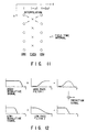
- Fig. 9 shows a function for determining which one is to be selected in the prediction-mode decision circuit 37, the high-resolution predictive signal 13 from the predictor 28 or the low-resolution predictive signal 16 from the predictor 36.
- the high-resolution predictive signal 13 in use, information of one or two motion vectors should be sent as the motion vector information 38.
- the low-resolution predictive signal 16 in use however, information of zero or one motion vector (one or two in the case where motion compensation from a low-resolution picture signal is to be also performed with respect to an odd field) has only to be sent as the motion vector information 39.
- the motion vector information 38 and 39 are transmitted after being subjected to variable-length coding in the variable-length coder 19.
- the numbers of bits (the bit amounts of variable-length codes) used in sending those motion vector information 38 and 39 is estimated and the difference therebetween is denoted by MV bitdiff .
- MSE pred1 indicates the prediction error power of the predictive signal 14 when the high-resolution predictive signal 13 from the predictor 28 is used
- MSE pred2 indicates the prediction error power of the predictive signal 14 when the low-resolution predictive signal 16 from the predictor 36 is used
- MSE pred1 and MSE pred2 ⁇ 2 -2MVbitdiff is compared.
- MSE pred1 ⁇ MSE pred2 ⁇ 2 -2MVbitdiff the high-resolution predictive signal 13 is selected by the selector switches 15 and 25, and when MSE pred1 > MSE pred2 ⁇ 2 -2MVbitdiff the low-resolution predictive signal 16 is selected by the selector switches 15 and 25.
- the optimal predictive coding of the input picture signal 11 becomes possible while suppressing the amount of information to be sent. This is particularly effective in the case where it is unnecessary to send motion vector with respect to the low-resolution predictive signal 16, e.g., when the low-resolution predictive signal 16 is prepared from a frame formed with merged fields.
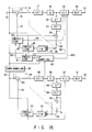
- Fig. 10 is a block diagram showing a specific example of the structure of the prediction-mode decision circuit 37 shown in Fig. 7 based on the above-described principle.
- the input picture signal (high-resolution picture signal) 11 and the high-resolution predictive signals 13 from the predictor 28 are input to a high-resolution prediction-mode decision circuit 41 where one of the high-resolution predictive signals 13 is selected.
- the difference between the selected high-resolution predictive signal and the input picture signal 11 is obtained by a subtracter 44, yielding a high-resolution prediction error signal.
- the low-resolution predictive signal 16 from the predictor 36 is input to a subtracter 45, which obtains the difference between this signal and the input picture signal 11, yielding a low-resolution prediction error signal.
- the motion vector information 38 and 39 from the predictors 28 and 36 are input to motion-vector information amount estimating circuits 42 and 43 to estimate the amounts of motion-vector information or the amounts of generated information from the variable-length coder 19 which correspond to the motion vector 38 and 39.
- a subtracter 46 obtains the difference between the estimated amounts of motion-vector information or the aforementioned MVbitdiff.
- An operation/decision circuit 47 obtains prediction error powers MSE pred1 and MSE pred2 of the high-resolution predictive signal and low-resolution predictive signal, and performs decision given by the equations (3) and (4) from the difference MV bittdiff between the two amounts of motion-vector information, using the decision function shown in Fig. 9. In accordance with the decision result, the circuit 47 controls the selector switches 15 and 25 in Fig. 7 and outputs the prediction mode signal 40.
- the predictive signal to be used in predictive coding of the high-resolution input picture signal is selected, thus advantageously improving the coding efficiency.
- a motion picture coding apparatus will now be described referring to Fig. 13.
- the prediction-mode decision circuit 37 may have the structure as shown in Fig. 10, or may have the same structure as the prior art.
- the selector switch 51 selects either an input picture signal 11 or a high-resolution low-resolution 14 output from a subtracter 12.
- the selector switch 54 selects either a signal 52 selected by the selector switch 51 or a low-resolution prediction error signal from a subtracter 53 (a difference signal between the signal 52 and a low-resolution predictive signal 16).
- the signal selected by this selector switch 54 is input to a DCT circuit 17.
- the selector switch 55 is controlled, interlocked with the selector switch 51, by the prediction-mode decision circuit 37, and selects "0" when the selector switch 51 selects the input picture signal 11, and the high-resolution predictive signal 13 when the switch 51 selects the high-resolution prediction error signal 14.
- the selector switch 56 is controlled, interlocked with the selector switch 54, by the prediction-mode decision circuit 37, and selects "0" when the selector switch 54 selects the signal from the selector switch 51, and the low-resolution predictive signal 16 when the switch 54 selects the low-resolution prediction error signal.
- the signal selected by the selector switch 55 is added to a signal from an inverse DCT circuit 23 in an adder 24a, and the signal selected by the selector switch 56 is added to a signal output from the adder 24a in an adder 24b, thus producing a local decoded signal 26.
- a predictor 28 detects a motion vector between the input picture signal 11, which is a high-resolution picture signal, and the high-resolution local decoded signal from a frame memory 27, and performs motion compensation inter-frame (inter-field) prediction using this motion vector to produce the high-resolution predictive signal 13 and outputs motion vector information 38.
- the predictive signal thus obtained includes three ways of prediction, namely the forward prediction, the backward prediction and the bidirectional prediction, and optimal prediction among those will be selected.
- the motion vector information 38 obtained by the predictor 28 is sent to a predictor 36 as well as to a variable-length coder 19.
- the predictor 36 accesses a frame memory 57, which stores plural frames of low-resolution local decoded signals from a local decoder 33, performs motion compensation on a signal input via an up-sampling circuit 35 from the frame memory 57 based on the motion vector information sent from the predictor 28, using the same method as the predictive signal preparing method selected by the predictor 28, and outputs the motion-compensated low-resolution predictive signal 16.
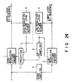
- Fig. 14 is a diagram showing how predictive coding of a high-resolution picture signal is carried out in this embodiment.
- This low-resolution predictive signal 16 is supplied to the subtracter 53 as a predictive signal for inter-frame (or inter-field) predictive coding on the high-resolution prediction error signal 14.
- a high-resolution picture signal e.g., an HDTV signal
- This input high-resolution picture signal 11 is input to a subtracter 12 where the difference between this signal and a predictive signal 13 is obtained, yielding a prediction error signal 14.
- a first selector switch 15 selects either the input high-resolution picture signal 11 or the prediction error signal 14.
- the signal selected by the selector switch 15 is subjected to DCT in a DCT (Discrete Cosine Transform) circuit 17.
- DCT coefficient data obtained by the DCT circuit 17 is quantized by an quantizer 18.
- the signal quantized by the quantizer 18 is sent to two ways; one is subjected to variable-length coding in a variable-length coder 19 and is then sent via a buffer 20 to a transmission system or a storage system (not shown) at a predetermined bit rate from an output terminal 21.
- the subtracter 12, selector switch 15, DCT circuit 17, quantizer 18 and variable-length coder 19 constitute a high-resolution picture coding circuit based on a motion-compensation adaptive predictive coding system.
- the other one of the signal quantized by the quantizer 18 and branched to two ways is sequentially subjected to opposite processes to those of the quantizer 18 and DCT circuit 17 in an inverse quantizer 22 and an inverse DCT circuit 23, and is then added to the predictive signal 13 in an adder 24.
- the second selector switch 25 is controlled, interlocked with the selector switch 15, and selects the output of the inverse DCT circuit 23 when the first selector switch 15 selects the input high-resolution picture signal 11, and the output of the adder 24 when the first selector switch 15 selects the prediction error signal 14, thereby producing a high-resolution local decoded signal 26.
- the inverse quantizer 22, inverse DCT circuit 23, adder 24 and second selector switch 25 constitute a high-resolution local decoding circuit.
- the high-resolution local decoded signal 26 is written in a frame memory 27.
- the output of the frame memory 27 is input to a first predictor 28 and is used to prepare a high-resolution predictive signal 40.
- the first predictor 28 detects a motion vector between the input high-resolution picture signal 11, which is a high-resolution picture signal, and the high-resolution local decoded signal from the frame memory 27, and performs motion compensation inter-frame (or inter-field) prediction using this motion vector to produce the high-resolution predictive signal 40 and outputs motion vector information 38.
- the prediction system in the first predictor 28 may be a method for adaptively switching between inter-frame prediction and inter-field prediction, or may be a system as described in the document "One Method of Adaptive Motion Compensation prediction for Interlaced Image” by Otaka, Yamakage and Yamaguchi, Picture Coding Symposium 1992 (PCSJ92), 5-13.
- the input high-resolution picture signal 11 is also input to a down-sampling circuit 29, which is means for converting a high-resolution picture signal to a low-resolution picture signal, and is down-sampled there to be converted into a low-resolution picture signal of a format defined by, for example, CCIR. Rec. 601.
- This low-resolution picture signal is a signal which, like the high-resolution picture signal, has been subjected to interlace scanning.
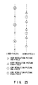
- the vertical pixel positions of the high-resolution picture signal and low-resolution picture signal have a relationship as shown in Fig. 25.
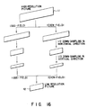
- the down-sampling circuit 29 performs processing shown in Fig. 16 or Fig. 17, for example.
- Fig. 16 illustrates a process of executing down-sampling in a field.
- the high-resolution picture signal is down-sampled in the horizontal direction and vertical direction every field, yielding a low-resolution picture signal.
- the relationship between the vertical pixel positions of the high-resolution picture signal and low-resolution picture signal differs between odd fields and even fields, so that the vertical down-sampling to be executed for odd fields would differ from that for even fields.
- down-sampling for odd fields is performed by executing filtering of odd taps using filter coefficients for odd fields, such as -29, 0, 88, 138, 88, 0, and -29/256
- down-sampling for even fields is performed by executing filtering of even taps using filter coefficients for even fields, such as -4, 23, 109, 109, 23, and -4/256.
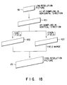
- Fig. 17 illustrates a process in a system of executing down-sampling after an interlaced picture is converted to a non-interlaced picture.
- a process or time spatial process adapted to motion is performed, as described in, for example, a document (1): C.L. Lee, S. Chang, C.W. Jen, "Motion Detection and Motion Adaptive Pro-scan Conversion", 1991 IEEE International Symposium on Circuits and Systems. Vol. 1, pp. 666-9, (June 1991), a document (2): A.
- a low-resolution picture signal 42 obtained by the down-sampling circuit 29 is coded by a low-resolution picture coding circuit of a motion-compensation adaptive predictive coding system, which comprises a subtracter 43, a selector switch 44, a DCT circuit 45, a quantizer 46 and a variable-length coder 47.
- the output of this low-resolution picture coding circuit is sent via a buffer 31 to a transmission system or a storage system from an output terminal 32 at a predetermined bit rate.
- the output of the quantizer 46 is subjected to local decoding by a low-resolution local decoding circuit, which comprises an inverse quantizer 48, an inverse DCT circuit 49, an adder 50 and a selector switch 51.
- This low-resolution local decoding circuit (the output of the selector switch 51), 56, is sent to two ways; one is written in a frame memory 52.
- the output of the frame memory 52 is input to a predictor 53 and is used to prepare a predictive signal 55 for coding a low-resolution picture signal.
- low-resolution local decoding circuit Since the operations of the above-described low-resolution picture coding circuit, low-resolution local decoding circuit, buffer 31, frame memory 52 and predictor 53 are the same as those of the aforementioned high-resolution picture coding circuit, high-resolution local decoding circuit, buffer 20, frame memory 27 and predictor 28, except for the difference in resolution of signals to be treated, their detailed descriptions will be omitted.
- the other part of the branched output 56 of the low-resolution local decoding circuit is input to an up-sampling circuit 60 to be up-sampled, yielding an up-sampling picture signal 65 which is a high-resolution picture signal.
- This up-sampling picture signal 65 is used to prepare a low-resolution predictive signal 62 in a second predictor 61.
- a third predictor 63 produces a predictive signal 13 based on the high-resolution predictive signal 40 and the low-resolution predictive signal 62.
- the third predictor 63 may perform its processing to select either the high-resolution predictive signal 40 or the low-resolution predictive signal 62 as the predictive signal 13, or may produce a signal, obtained by weighting and adding those signals, as the predictive signal 13.
- the selection between the high-resolution predictive signal 40 and the low-resolution predictive signal 62, or the determination of the weighting coefficient has only to be performed by selecting the one which makes the square errors of the predictive signal 13 and the input high-resolution picture signal 11.
- the third predictor 63 outputs information, which indicates which signal, the high-resolution predictive signal 40 or the low-resolution predictive signal 62, has been selected as the predictive signal 13, or information 64 indicating the weighting coefficient used in prediction. This information is multiplexed with the output of the high-resolution picture coding circuit in the variable-length coder 19 before being sent out from an output terminal 21.
- the up-sampling circuit 60 which characterizes this invention, will be described in detail below.
- Fig. 18 is for explaining the process of the up-sampling circuit 60.
- the low-resolution local decoded signal 56 which is the output of the low-resolution local decoding circuit, is up-sampled to be doubled in the horizontal direction, and is then subjected to vertical up-sampling, thus yielding the up-sampling picture signal 65, which is a high-resolution picture signal.
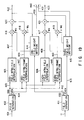
- Fig. 19 is a block diagram showing a vertical up-sampling circuit portion of the up-sampling circuit 60, which performs vertical up-sampling in Fig. 18.
- this vertical up-sampling circuit portion an intra-field up-sampling signal and an intra-frame up-sampling signal are adaptively weighted and added.
- a signal 401 obtained by horizontal up-sampling of the low-resolution local decoded signal 56, which is input from a horizontal up-sampling circuit portion in the up-sampling circuit 60, which performs horizontal up-sampling in Fig. 18, is separated into an odd-field signal 403 and an even-field 404 in a first field separator 402.
- the odd-field signal 403 and even-field signal 404 are subjected to vertical interpolation in an odd-numbered field intra-field interpolation circuit 405 and an even-numbered field intra-field interpolation circuit 406, respectively, using the signals in the individual fields, thus producing an odd-field intra-field interpolation signal 407 and even-field intra-field interpolation signal 408.
- the odd-field intra-field interpolation circuit 405 and the even-field intra-field interpolation circuit 406 perform processes to prepare a signal marked by "X" from a signal marked by "o” and interpolate a signal marked by " ⁇ ” with a signal marked by " ⁇ ” in Fig. 25, and, more specifically, perform the computations to execute linear interpolation of, for example, upper and lower lines in accordance with the distance, which are expressed by the following equations.
- An odd-numbered field intra-frame interpolation circuit 447 and an even-numbered field intra-frame interpolation circuit 448 perform field-overlapped vertical interpolation using signals of two fields to produce an odd-field intra-frame interpolation signal 409 and an even-field intra-frame interpolation signal 410.
- This process is to interpolate a signal marked by "X” and a signal marked by " ⁇ ” using both of a signal marked by "o” and a signal marked by " ⁇ ”, and performs computations expressed by, for example, the following equations.
- the odd (even)-field intra-field interpolation signal 407 (408) and the odd (even)-field intra-frame interpolation signal 409 (410) are respectively multiplied by weighting coefficients Wo(We) and 1-Wo(1-We) in multipliers 416 (417) and 418 (419), and are then added by an adder 420 (421), yielding an odd (even)-field up-sampling picture signal 422 (423).
- the weighting coefficients Wo and We (0 ⁇ Wo, We ⁇ 1) are determined with the input high-resolution picture signal 11 taken as a reference signal. More specifically, the input high-resolution picture signal 11 is separated, by a second field separator 411, into a high-resolution odd-field signal 412 and a high-resolution even-field signal 413, which are in turn input to an odd-numbered field weighting decision circuit 414 and an even-numbered field weighting decision circuit 415, respectively. For instance, of several candidates for the weighting coefficients, those which minimize the square mean values or the sums of the absolute values of the differences between the up-sampling picture signals 422 and 423 and the input signals 412 and 413, have only to be selected. Alternatively, coding may be tried to select that weighting coefficient which minimizes the amount of codes. Selective information 430 and 431 of the weighting coefficients are sent as side information 440.
- the candidates for the weighting coefficients Wo and We may only be 0 and 1.
- either the intra-field up-sampling or the intra-frame up-sampling is used, so that the multipliers 416 to 419 and the adders 420 and 421 are unnecessary, and instead, a switch should be provided which selects either the intra-frame up-sampling signal or the intra-field up-sampling signal for each field in accordance with motion decision information.
- the weighting coefficients may be shared with the other selective information necessary for coding, thus eliminating the need for the side information. For instance, in the case of the coding system for switching between frame DCT and field DCT for each given area of a picture, the weighting coefficients may be determined based on this switching information. Conversely, the weighting coefficients may be determined in the previously described manner, and whether to use the frame DCT or field DCT may be determined based on the coefficients. In the case of the system of switching prediction methods, such as motion compensation, for each given area of a picture, the weighting coefficients may be determined based on this switching information or the motion vector.
- the weighting coefficients may be determined based on the already-encoded information, such as the coding mode, the motion vector the size of an inter-frame difference of a local decoded picture for an already-coded area around an area to be coded, the coding mode, the motion vector and the size of an inter-frame difference of a local decoded picture for an already-coded frame, and the local decoded picture, thereby reducing the amount of the weighting coefficient information.
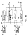
- Fig. 20 is a block diagram showing the second example of the vertical up-sampling circuit portion of the up-sampling circuit 60.
- first and second field separators 502 and 511 perform the same processes as the first and second field separators 402 and 411 in Fig. 19.
- An odd-numbered field motion-compensation up-sampling circuit 505 and even-numbered field motion-compensation up-sampling circuit 506 perform up-sampling motion-compensated from an odd-field signal 503 and an even-field signal 504 based on motion vectors 509 and 510 detected by first and second motion-vector detectors 507 and 508, yielding an odd-field up-sampling picture signal 422 and an even-field up-sampling picture signal 423, respectively.
- the first motion-vector detector 507 detects the motion vector from the even-field signal 504 to a high-resolution odd-field signal 512.
- the motion vector will not be detected and the low-resolution signal at the same position at the up-sampling time is used directly.
- the signal which is not spatially located at the same position as the low-resolution odd-field signal (signal marked by "X” and not overlapping the mark "o” in Figs.
- the motion vector from the low-resolution even-field signal 504 (signal marked by " ⁇ ") with the square mean value or the sum of the absolute values of the differences, etc., taken as an evaluation reference for every given unit area, or in such a way as to minimize the amount of codes originating from some temporary coding, and a signal obtained by subjecting the low-resolution even-field signal to motion compensation based on this motion vector.
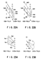
- the second motion-vector detector 507 detects the motion vector from the odd-field signal 503 to a high-resolution even-field signal 513. At this time, either one of Figs. 22A and 22B is fixed, or motion compensation which provides a smaller square error with, for example, the input high-resolution picture signal 11 is selected, based on the motion vector 509 obtained by the first motion-vector detector 508.
- a signal 652 which is obtained by subjecting a low-resolution odd-field signal to motion compensation using a vector 651, attained by reversing the motion vector 509 from the low-resolution even field to the high-resolution odd field in both the horizontal and vertical directions and shifting it downward by + 1/2, is used as an up-sampling signal for odd lines
- a signal 654 which is obtained by subjecting a low-resolution odd-field signal to motion compensation using a vector 653, attained by reversing the motion vector 509 in both the horizontal and vertical directions is used directly or an interpolation signal with a low-resolution even-field signal 655 thereabove by one line is used as an up-sampling signal for even lines.
- a signal 662 which is obtained by subjecting a low-resolution odd-field signal to motion compensation using a vector 661, attained by reversing the motion vector 509 in both the horizontal and vertical directions and shifting it upward by + 1/2, is used as an up-sampling signal for even lines
- a signal 664 which is obtained by subjecting a low-resolution odd-field signal to motion compensation using a vector 663, attained by reversing the motion vector 509 in both the horizontal and vertical directions is used directly or an interpolation signal with a low-resolution even-field signal 665 thereunder by one line is used as an up-sampling signal for odd lines.
- Information 520 indicating which one of the motion vector 509 and Figs. 22A and 22B has been selected is sent as side information 440.
- the motion vector may be detected by conducting a search around a vector obtained by compensating the motion vector of a low-resolution picture or a high-resolution picture in accordance with the field time. Accordingly, even if the search range for the motion vector is made narrower than the case of the direct searching, nearly the same advantage will be obtained.
- this motion vector information can also be obtained on the decoder side, so that the motion vectors obtained by the motion-vector detectors 507 and 508 and information about the difference between those motion vectors may be transmitted. This will reduce the amount of the motion vector information.
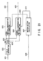
- Fig. 21 is a block diagram showing the third example of the vertical up-sampling circuit portion of the up-sampling circuit 60.
- a field separator 602 performs the same processing as the field separator 402 in Fig. 19.
- An odd-numbered field motion-compensation up-sampling circuit 605 and an even-numbered field motion-compensation up-sampling circuit 606 perform up-sampling of an odd-field signal 603 and an even-field signal 604, which has undergone motion compensation based on the motion vectors 609 and 610 computed by a motion-vector computing circuit 607, thus yielding an odd-field up-sampling picture signal 422 and an even-field up-sampling picture signal 423.
- the motion-vector computing circuit 607 computes the motion vector which is obtained by compensating the motion vector 608, used in the prediction of the low-resolution signal coding, in accordance with the field distance.
- vectors 762 and 763 attained by rounding a vector 761, obtained by compensating the low-resolution motion vector in accordance with the field distance as shown in, for example, Fig. 23A, for each line of the low-resolution, or a vector 764 obtained by performing the rounding for every 1/2 line, odd-field signal may be used, and when the motion vector is rounded every 1/2 line, the signal of a non-integer line may be prepared by interpolation of the mentioned line.
- a vector 752 attained by rounding a vector 751, obtained by compensating the low-resolution motion vector in accordance with the field distance as shown in, for example, Fig. 23B, for each line of the low-resolution, or a vector 753 obtained by performing the rounding for every 1/2 line, odd-field signal may be used.
- odd fields if there is a line located at spatially the same position in the low-resolution picture odd-field, the signal of that line is used, and motion compensation will be performed only on those lines which are not located at spatially the same positions.
- a signal motion-compensated from the opposite field to the low-resolution local decoded signal may be used directly as an up-sampling signal for both the odd and even fields, or a signal weighted with the low-resolution local decoded signal of the same field may be used as an up-sampling signal.
- the weighting coefficient may be fixed or may be determined based on the magnitude of the motion vector, or the size of the vector dropped off when the motion vector is rounded.
- the weighting coefficient used in this weighting and addition may be selected in such a way as to minimize the square error with the high-resolution input signal and may be sent as side information, or may be determined in accordance with the magnitude of the high-resolution motion vector.
- the weighting coefficient in use may be different for each field. In this case, since the high-resolution motion vector information can be obtained on the decoder side, the motion vector in use may be computed based on the high-resolution motion vector compensated in accordance with the field time.
- the up-sampling circuit having the vertical up-sampling circuit portion shown in Fig. 20 is used, the difference between the motion vectors used in coding a high-resolution picture may be obtained and sent as the motion vector information.
- this invention will provide a motion picture coding apparatus, which has a higher coding efficiency than the prior art, has a scalability to ensure simultaneous coding of a plurality of picture signals of different resolutions, subjected to interlace scanning, like an HDTV signal and the current TV signal, and which performs improved up-sampling at the time of performing prediction for the coding of an interlace-scanned high-resolution picture signal, obtained by up-sampling an interlace-scanned low-resolution local decoded signal, thus improving the prediction efficiency.
Description
- fo :
- odd-
field signal 403, - fe :
- even-
field signal 404, - fso:
- odd-field
intra-field interpolation signal 407, - fse:
- even-field
intra-field interpolation signal 408, and - i :
- line number.
Claims (8)
- Motion picture coding apparatus comprising:first coding means for prediction-coding of a high-resolution interlaced picture as a frame picture;first local decoding means for decoding a coding result from said first coding means to obtain a high-resolution local decoded signal;first prediction means for attaining a high-resolution predictive signal from said high-resolution local decoded signal;converting means for converting said high-resolution interlaced picture to a low-resolution picture signal;second coding means for coding said low-resolution picture signal;second local decoding means for decoding a coding result from said second coding means to obtain a low-resolution local decoded signal;up-sampling means for up-sampling said low-resolution local decoded signal; andsecond predicting means for attaining a low-resolution predictive signal from a signal up-sampled by said up-sampling means,whereby a predictive signal is produced from said low-resolution predictive signal and said high-resolution predictive signal.
- Motion picture coding apparatus according to claim 1, wherein said converting means converts said high-resolution interlaced picture to a low-resolution non-interlaced picture, the apparatus further comprising means for selecting, for each of even and odd fields, an optimal one of said low-resolution predictive signal and said high-resolution predictive signal, which are used when performing predictive coding as said frame picture.
- Motion picture coding apparatus according to claim 1, wherein said second predicting means supplies a signal obtained by shifting said signal up-sampled by said up-sampling means by an amount corresponding to motion within a field period, to candidates for said low-resolution predictive signal.
- Motion picture coding apparatus according to claim 1,whereby as a prediction mode used when prediction-coding said high-resolution interlaced picture, a predictive signal is attained by a weighted sum of said low-resolution predictive signal and said high-resolution predictive signal.
- Motion picture coding apparatus according to claim 3, wherein an amount of shift corresponding to motion in said field period is obtained by dividing a shift amount necessary to prepare said high-resolution predictive signal by an inter-field distance, and a signal produced from a low-resolution predictive signal obtained by said amount of shift and said high-resolution predictive signal is added to candidates for said predictive signal.
- Motion picture coding apparatus according to claim 3, wherein an amount of shift corresponding to motion in said field period is obtained as an optimal shift amount to optimise an evaluation function attained by searching around a reference shift amount, obtained by dividing a shift amount necessary to prepare said high-resolution predictive signal by an inter-field distance, and a difference between said optimal shift amount and said reference shift amount is transmitted.
- Motion picture coding apparatus according to claim 3 or 6, wherein said first predicting means has means for outputting, as said high-resolution predictive signal, a signal obtained by adding signals, undergone conversion having a mutually complementary characteristic with respect to both of said high-resolution local decoded signal and said low-resolution local decoded signal.
- Motion picture coding apparatus according to claim 1, the apparatus further comprises:prediction-signal selecting means for selecting a predictive signal used by said first coding means from said high-resolution predictive signal and said low-resolution predictive signal on the basis of a determination criterion where a prediction error power and an amount of additional information generated by said first coding means are considered in cases when said high-resolution predictive signal and said low-resolution predictive signal are used in predictive coding in said first coding means.
Applications Claiming Priority (7)
| Application Number | Priority Date | Filing Date | Title |
|---|---|---|---|
| JP4567892 | 1992-03-03 | ||
| JP45678/92 | 1992-03-03 | ||
| JP253466/92 | 1992-08-31 | ||
| JP25346692A JP3032088B2 (en) | 1992-03-03 | 1992-08-31 | Video encoding device |
| JP349536/92 | 1992-12-28 | ||
| JP34953692A JPH06205397A (en) | 1992-12-28 | 1992-12-28 | Dynamic image coding device |
| PCT/JP1993/000275 WO1993018618A1 (en) | 1992-03-03 | 1993-03-03 | Time-varying image encoder |
Publications (3)
| Publication Number | Publication Date |
|---|---|
| EP0631444A1 EP0631444A1 (en) | 1994-12-28 |
| EP0631444A4 EP0631444A4 (en) | 1995-01-11 |
| EP0631444B1 true EP0631444B1 (en) | 1998-12-23 |
Family
ID=27292340
Family Applications (1)
| Application Number | Title | Priority Date | Filing Date |
|---|---|---|---|
| EP93905614A Expired - Lifetime EP0631444B1 (en) | 1992-03-03 | 1993-03-03 | Time-varying image encoder |
Country Status (4)
| Country | Link |
|---|---|
| US (2) | US5418570A (en) |
| EP (1) | EP0631444B1 (en) |
| DE (1) | DE69322769T2 (en) |
| WO (1) | WO1993018618A1 (en) |
Families Citing this family (88)
| Publication number | Priority date | Publication date | Assignee | Title |
|---|---|---|---|---|
| DE69322769T2 (en) * | 1992-03-03 | 1999-07-22 | Toshiba Kawasaki Kk | CODE FOR CHANGEABLE IMAGES |
| US5614952A (en) * | 1994-10-11 | 1997-03-25 | Hitachi America, Ltd. | Digital video decoder for decoding digital high definition and/or digital standard definition television signals |
| JP3374989B2 (en) * | 1993-03-26 | 2003-02-10 | ソニー株式会社 | Image signal encoding method and image signal encoding device, image signal decoding method and image signal decoding device |
| KR970000683B1 (en) * | 1993-05-31 | 1997-01-16 | 삼성전자 주식회사 | Resolution adaptive video compression/decompression method and apparatus |
| BE1007681A3 (en) * | 1993-10-29 | 1995-09-12 | Philips Electronics Nv | Device for transfer of television images and device for receiving it. |
| US6137835A (en) * | 1993-11-16 | 2000-10-24 | Canon Kabushiki Kaisha | Picture coding apparatus using orthogonal transforms |
| EP0701763A1 (en) * | 1994-03-30 | 1996-03-20 | Apple Computer, Inc. | Video image sampling lattice for vhs format magnetic tape applications |
| EP0720383B1 (en) * | 1994-12-30 | 2000-09-13 | Daewoo Electronics Co., Ltd | Method and apparatus for detecting motion vectors in a frame decimating video encoder |
| US5943096A (en) * | 1995-03-24 | 1999-08-24 | National Semiconductor Corporation | Motion vector based frame insertion process for increasing the frame rate of moving images |
| JPH09121358A (en) * | 1995-10-25 | 1997-05-06 | Matsushita Electric Ind Co Ltd | Picture coding/decoding device and its method |
| US5825927A (en) * | 1996-01-16 | 1998-10-20 | Hitachi America, Ltd. | Methods and apparatus for encoding video data in a manner that is well suited for decoding by regular or downconverting decoders |
| US5768537A (en) * | 1996-02-22 | 1998-06-16 | International Business Machines Corporation | Scalable MPEG2 compliant video encoder |
| US6031575A (en) * | 1996-03-22 | 2000-02-29 | Sony Corporation | Method and apparatus for encoding an image signal, method and apparatus for decoding an image signal, and recording medium |
| JPH1023425A (en) * | 1996-07-01 | 1998-01-23 | Sony Corp | Device and method for encoding picture, device and method for decoding picture and picture recording medium |
| JP3224514B2 (en) * | 1996-08-21 | 2001-10-29 | シャープ株式会社 | Video encoding device and video decoding device |
| JP4034380B2 (en) * | 1996-10-31 | 2008-01-16 | 株式会社東芝 | Image encoding / decoding method and apparatus |
| US6259738B1 (en) * | 1996-10-31 | 2001-07-10 | Kabushiki Kaisha Toshiba | Video encoding apparatus and video decoding apparatus |
| CN1243635A (en) | 1997-01-10 | 2000-02-02 | 松下电器产业株式会社 | Image processing method, image processing device, and data recording medium |
| JPH10304381A (en) * | 1997-05-01 | 1998-11-13 | Fujitsu Ltd | Moving image encoding device/method |
| JPH10327415A (en) * | 1997-05-22 | 1998-12-08 | Mitsubishi Electric Corp | Motion vector detector |
| JP3844844B2 (en) * | 1997-06-06 | 2006-11-15 | 富士通株式会社 | Moving picture coding apparatus and moving picture coding method |
| JPH1169345A (en) * | 1997-06-11 | 1999-03-09 | Fujitsu Ltd | Inter-frame predictive dynamic image encoding device and decoding device, inter-frame predictive dynamic image encoding method and decoding method |
| AU731906B2 (en) | 1997-07-18 | 2001-04-05 | Sony Corporation | Image signal multiplexing apparatus and methods, image signal demultiplexing apparatus and methods, and transmission media |
| JP3813320B2 (en) * | 1997-08-27 | 2006-08-23 | 株式会社東芝 | Motion vector detection method and apparatus |
| JP3099809B2 (en) * | 1998-06-04 | 2000-10-16 | 日本電気株式会社 | Frame display method and apparatus using single field data |
| JP2000023162A (en) | 1998-06-29 | 2000-01-21 | Sony Corp | Device and method for encoding |
| GB9817765D0 (en) * | 1998-08-17 | 1998-10-14 | James Dilip D | Fixed length coding for digital image compression |
| US6628714B1 (en) * | 1998-12-18 | 2003-09-30 | Zenith Electronics Corporation | Down converting MPEG encoded high definition sequences to lower resolution with reduced memory in decoder loop |
| JP2000244921A (en) * | 1999-02-24 | 2000-09-08 | Matsushita Electric Ind Co Ltd | Method and device for coding video image |
| GB2348064A (en) * | 1999-03-16 | 2000-09-20 | Mitsubishi Electric Inf Tech | Motion vector field encoding |
| US6907073B2 (en) * | 1999-12-20 | 2005-06-14 | Sarnoff Corporation | Tweening-based codec for scaleable encoders and decoders with varying motion computation capability |
| CN100481955C (en) * | 2000-12-06 | 2009-04-22 | 真实网络公司 | Method and apparatus for intra coding video data |
| US6765964B1 (en) | 2000-12-06 | 2004-07-20 | Realnetworks, Inc. | System and method for intracoding video data |
| US20020126759A1 (en) * | 2001-01-10 | 2002-09-12 | Wen-Hsiao Peng | Method and apparatus for providing prediction mode fine granularity scalability |
| US7113223B2 (en) * | 2001-04-20 | 2006-09-26 | Mti Film Llc | High resolution color conforming |
| PT1978747E (en) | 2001-11-29 | 2014-07-24 | Panasonic Ip Corp America | Coding distortion removal method |
| DE60230666D1 (en) | 2001-11-29 | 2009-02-12 | Panasonic Corp | PROCESS FOR ELIMINATING CODING FORCED AND METHOD FOR VIDEO CODING AND DECODING |
| US7003035B2 (en) | 2002-01-25 | 2006-02-21 | Microsoft Corporation | Video coding methods and apparatuses |
| JP3840129B2 (en) * | 2002-03-15 | 2006-11-01 | 株式会社東芝 | Motion vector detection method and apparatus, interpolation image generation method and apparatus, and image display system |
| US7305034B2 (en) * | 2002-04-10 | 2007-12-04 | Microsoft Corporation | Rounding control for multi-stage interpolation |
| US7170937B2 (en) * | 2002-05-01 | 2007-01-30 | Texas Instruments Incorporated | Complexity-scalable intra-frame prediction technique |
| JP3839353B2 (en) * | 2002-05-27 | 2006-11-01 | 株式会社モノリス | Image encoding method and apparatus, and image decoding method and apparatus |
| US7386048B2 (en) * | 2002-05-28 | 2008-06-10 | Sharp Laboratories Of America, Inc. | Methods and systems for image intra-prediction mode organization |
| US20040001546A1 (en) | 2002-06-03 | 2004-01-01 | Alexandros Tourapis | Spatiotemporal prediction for bidirectionally predictive (B) pictures and motion vector prediction for multi-picture reference motion compensation |
| US7154952B2 (en) | 2002-07-19 | 2006-12-26 | Microsoft Corporation | Timestamp-independent motion vector prediction for predictive (P) and bidirectionally predictive (B) pictures |
| JP2004179953A (en) * | 2002-11-27 | 2004-06-24 | Matsushita Electric Ind Co Ltd | Image server, image server system, and network transmission and display method of camera image |
| US7720151B2 (en) * | 2003-02-11 | 2010-05-18 | Texas Instruments Incorporated | Motion estimation using early decision for goodness of estimation with quick convergence feedback |
| US8761252B2 (en) | 2003-03-27 | 2014-06-24 | Lg Electronics Inc. | Method and apparatus for scalably encoding and decoding video signal |
| KR20060105409A (en) * | 2005-04-01 | 2006-10-11 | 엘지전자 주식회사 | Method for scalably encoding and decoding video signal |
| US7580460B2 (en) * | 2003-03-28 | 2009-08-25 | Sony Corporation | Video encoder with multiple outputs having different attributes |
| US7609763B2 (en) | 2003-07-18 | 2009-10-27 | Microsoft Corporation | Advanced bi-directional predictive coding of video frames |
| US8064520B2 (en) | 2003-09-07 | 2011-11-22 | Microsoft Corporation | Advanced bi-directional predictive coding of interlaced video |
| KR101193698B1 (en) * | 2004-06-03 | 2012-10-22 | 힐크레스트 래보래토리스, 인크. | Client-server architectures and methods for zoomable user interface |
| JP2006174415A (en) * | 2004-11-19 | 2006-06-29 | Ntt Docomo Inc | Image decoding apparatus, image decoding program, image decoding method, image encoding apparatus, image encoding program, and image encoding method |
| WO2006104366A1 (en) * | 2005-04-01 | 2006-10-05 | Lg Electronics Inc. | Method for scalably encoding and decoding video signal |
| US8660180B2 (en) * | 2005-04-01 | 2014-02-25 | Lg Electronics Inc. | Method and apparatus for scalably encoding and decoding video signal |
| EP1878249B1 (en) * | 2005-04-01 | 2020-03-04 | LG Electronics, Inc. | Method for scalably decoding a video signal |
| KR100883604B1 (en) * | 2005-04-01 | 2009-02-13 | 엘지전자 주식회사 | Method for scalably encoding and decoding video signal |
| KR100878825B1 (en) * | 2005-04-01 | 2009-01-14 | 엘지전자 주식회사 | Method for scalably encoding and decoding video signal |
| US7636480B2 (en) * | 2005-06-10 | 2009-12-22 | Xerox Corporation | Super resolution encoding |
| US8755434B2 (en) * | 2005-07-22 | 2014-06-17 | Lg Electronics Inc. | Method and apparatus for scalably encoding and decoding video signal |
| FR2889778A1 (en) * | 2005-08-12 | 2007-02-16 | Thomson Licensing Sas | METHOD FOR ENCODING AND DECODING VIDEO IMAGES WITH SPACE SCALABILITY |
| FR2896371B1 (en) * | 2006-01-19 | 2008-11-07 | Canon Kk | METHOD AND DEVICE FOR PROCESSING A SEQUENCE OF DIGITAL IMAGES WITH AN EXTENDABLE FORMAT |
| KR101330630B1 (en) | 2006-03-13 | 2013-11-22 | 삼성전자주식회사 | Method and apparatus for encoding moving picture, method and apparatus for decoding moving picture, applying adaptively an optimal prediction mode |
| US7817184B1 (en) | 2006-03-15 | 2010-10-19 | The Directv Group, Inc. | Methods and apparatus to test receivers |
| CN101606385B (en) * | 2006-08-21 | 2011-06-01 | 三叉微系统(远东)有限公司 | Motion-compensated processing of image signals |
| FR2906433B1 (en) * | 2006-09-22 | 2009-02-27 | Canon Kk | METHODS AND DEVICES FOR ENCODING AND DECODING IMAGES, COMPUTER PROGRAM USING THEM AND INFORMATION SUPPORT FOR IMPLEMENTING THEM |
| US8254455B2 (en) | 2007-06-30 | 2012-08-28 | Microsoft Corporation | Computing collocated macroblock information for direct mode macroblocks |
| JP5286805B2 (en) * | 2008-01-31 | 2013-09-11 | 沖電気工業株式会社 | Motion vector detection apparatus and method, moving picture encoding apparatus and method, and moving picture decoding apparatus and method |
| BRPI0915971A2 (en) * | 2008-07-25 | 2019-02-26 | Sony Corp | device and image processing method |
| US8254467B2 (en) * | 2008-10-30 | 2012-08-28 | Sensio Technologies Inc. | Method and system for scaling compressed image frames |
| US8605782B2 (en) | 2008-12-25 | 2013-12-10 | Dolby Laboratories Licensing Corporation | Reconstruction of de-interleaved views, using adaptive interpolation based on disparity between the views for up-sampling |
| US8311115B2 (en) * | 2009-01-29 | 2012-11-13 | Microsoft Corporation | Video encoding using previously calculated motion information |
| US8396114B2 (en) * | 2009-01-29 | 2013-03-12 | Microsoft Corporation | Multiple bit rate video encoding using variable bit rate and dynamic resolution for adaptive video streaming |
| US8189666B2 (en) | 2009-02-02 | 2012-05-29 | Microsoft Corporation | Local picture identifier and computation of co-located information |
| US8270473B2 (en) * | 2009-06-12 | 2012-09-18 | Microsoft Corporation | Motion based dynamic resolution multiple bit rate video encoding |
| US9654792B2 (en) | 2009-07-03 | 2017-05-16 | Intel Corporation | Methods and systems for motion vector derivation at a video decoder |
| US8675137B2 (en) * | 2010-04-13 | 2014-03-18 | Newport Media, Inc. | Apparatus and method for adaptive filtering |
| US8705616B2 (en) | 2010-06-11 | 2014-04-22 | Microsoft Corporation | Parallel multiple bitrate video encoding to reduce latency and dependences between groups of pictures |
| US8548062B2 (en) * | 2010-07-16 | 2013-10-01 | Sharp Laboratories Of America, Inc. | System for low resolution power reduction with deblocking flag |
| US9602819B2 (en) * | 2011-01-31 | 2017-03-21 | Apple Inc. | Display quality in a variable resolution video coder/decoder system |
| US9066110B2 (en) | 2011-03-08 | 2015-06-23 | Texas Instruments Incorporated | Parsing friendly and error resilient merge flag coding in video coding |
| US9591318B2 (en) | 2011-09-16 | 2017-03-07 | Microsoft Technology Licensing, Llc | Multi-layer encoding and decoding |
| US11089343B2 (en) | 2012-01-11 | 2021-08-10 | Microsoft Technology Licensing, Llc | Capability advertisement, configuration and control for video coding and decoding |
| GB2496015B (en) | 2012-09-05 | 2013-09-11 | Imagination Tech Ltd | Pixel buffering |
| JP2017011458A (en) * | 2015-06-19 | 2017-01-12 | 富士通株式会社 | Encoded data generation program, encoded data generation method and encoded data generation device |
| US10187655B2 (en) * | 2015-09-30 | 2019-01-22 | Apple Inc. | Memory-to-memory low resolution motion estimation systems and methods |
| CN113228675A (en) * | 2018-12-21 | 2021-08-06 | 北京字节跳动网络技术有限公司 | Motion vector bit depth in video processing |
Family Cites Families (18)
| Publication number | Priority date | Publication date | Assignee | Title |
|---|---|---|---|---|
| JPS56143776A (en) * | 1980-04-09 | 1981-11-09 | Nec Corp | Interframe encoder |
| JPS58191586A (en) * | 1982-05-01 | 1983-11-08 | Nippon Hoso Kyokai <Nhk> | Picture signal inserting system |
| JPS58210777A (en) * | 1982-06-02 | 1983-12-08 | Hitachi Ltd | Picture transmitter |
| JPS6156587A (en) * | 1984-07-27 | 1986-03-22 | Fujitsu Ltd | Optimum block detector circuit |
| JPS6232787A (en) * | 1985-08-05 | 1987-02-12 | Fujitsu Ltd | Subsampling type vector quantization system |
| US4858026A (en) * | 1986-04-14 | 1989-08-15 | U.S. Philips Corporation | Image display |
| DE3851786T2 (en) * | 1987-06-09 | 1995-03-09 | Sony Corp | Selection of a motion vector in television pictures. |
| GB2231745B (en) * | 1989-04-27 | 1993-07-07 | Sony Corp | Motion dependent video signal processing |
| AU612543B2 (en) * | 1989-05-11 | 1991-07-11 | Panasonic Corporation | Moving image signal encoding apparatus and decoding apparatus |
| US5091782A (en) * | 1990-04-09 | 1992-02-25 | General Instrument Corporation | Apparatus and method for adaptively compressing successive blocks of digital video |
| WO1992006563A2 (en) * | 1990-10-09 | 1992-04-16 | N.V. Philips' Gloeilampenfabrieken | Coding system for digital signals corresponding to television pictures and corresponding decoding system |
| JPH04177992A (en) * | 1990-11-09 | 1992-06-25 | Victor Co Of Japan Ltd | Picture coder having hierarchical structure |
| JP2708971B2 (en) * | 1991-04-09 | 1998-02-04 | ポリプラスチックス株式会社 | Injection molding method, injection mold and injection molded product |
| US5398078A (en) * | 1991-10-31 | 1995-03-14 | Kabushiki Kaisha Toshiba | Method of detecting a motion vector in an image coding apparatus |
| DE69322769T2 (en) * | 1992-03-03 | 1999-07-22 | Toshiba Kawasaki Kk | CODE FOR CHANGEABLE IMAGES |
| US5436665A (en) * | 1992-03-03 | 1995-07-25 | Kabushiki Kaisha Toshiba | Motion picture coding apparatus |
| NL9201594A (en) * | 1992-09-14 | 1994-04-05 | Nederland Ptt | System comprising at least one encoder for encoding a digital signal and at least one decoder for decoding an encoded digital signal, and encoder and decoder for use in the system. |
| JP3381855B2 (en) * | 1992-12-28 | 2003-03-04 | ソニー株式会社 | Image signal encoding method and image signal encoding device, image signal decoding method and image signal decoding device |
-
1993
- 1993-03-03 DE DE69322769T patent/DE69322769T2/en not_active Expired - Fee Related
- 1993-03-03 US US08/150,035 patent/US5418570A/en not_active Expired - Lifetime
- 1993-03-03 WO PCT/JP1993/000275 patent/WO1993018618A1/en active IP Right Grant
- 1993-03-03 EP EP93905614A patent/EP0631444B1/en not_active Expired - Lifetime
-
1995
- 1995-01-19 US US08/374,911 patent/US5677735A/en not_active Expired - Lifetime
Also Published As
| Publication number | Publication date |
|---|---|
| EP0631444A4 (en) | 1995-01-11 |
| US5677735A (en) | 1997-10-14 |
| DE69322769T2 (en) | 1999-07-22 |
| EP0631444A1 (en) | 1994-12-28 |
| US5418570A (en) | 1995-05-23 |
| DE69322769D1 (en) | 1999-02-04 |
| WO1993018618A1 (en) | 1993-09-16 |
Similar Documents
| Publication | Publication Date | Title |
|---|---|---|
| EP0631444B1 (en) | Time-varying image encoder | |
| US5436665A (en) | Motion picture coding apparatus | |
| JP2924431B2 (en) | Coding method | |
| US7535961B2 (en) | Video encoding/decoding apparatus and method for color image | |
| US5508746A (en) | Advanced television system | |
| JP3164031B2 (en) | Moving image encoding / decoding device, moving image encoding / decoding method, and moving image encoded recording medium | |
| US7116372B2 (en) | Method and apparatus for deinterlacing | |
| EP0618731B1 (en) | High efficiency encoding of picture signals | |
| US7801218B2 (en) | Method or device for coding a sequence of source pictures | |
| EP2271115B1 (en) | Macroblock level adaptive frame/field coding for digital video content | |
| US5446498A (en) | Scaling interlaced images for encoding and decoding of digital video signals of multiple scanning standards | |
| KR100272812B1 (en) | Video signal coder | |
| JPH09238366A (en) | Image coder, image encoder, and coding decoding system | |
| JP3032088B2 (en) | Video encoding device | |
| EP0599529B1 (en) | Method and apparatus for picture coding and method and apparatus for picture decoding | |
| KR100345968B1 (en) | High efficient coder for picture signal, decoder and recording medium | |
| EP0907289A1 (en) | Efficient coding apparatus for picture signal and decoding apparatus therefor | |
| JPH07212761A (en) | Hierarchical coder and hierarchical decoder | |
| JPH06205397A (en) | Dynamic image coding device | |
| JP3432886B2 (en) | Hierarchical encoding / decoding apparatus and method, and transmission / reception system | |
| JP2001086508A (en) | Method and device for moving image decoding | |
| JPH0698311A (en) | High efficiency coding and decoding device for picture signal | |
| KR960007206B1 (en) | Progressive scan conversion device combined with video decoder | |
| JP2852118B2 (en) | Moving picture coding method and moving picture coding apparatus | |
| KR100441559B1 (en) | Apparatus and method for transformation of scanning format |
Legal Events
| Date | Code | Title | Description |
|---|---|---|---|
| PUAI | Public reference made under article 153(3) epc to a published international application that has entered the european phase |
Free format text: ORIGINAL CODE: 0009012 |
|
| 17P | Request for examination filed |
Effective date: 19931119 |
|
| AK | Designated contracting states |
Kind code of ref document: A1 Designated state(s): DE FR GB |
|
| A4 | Supplementary search report drawn up and despatched | ||
| AK | Designated contracting states |
Kind code of ref document: A4 Designated state(s): DE FR GB |
|
| RHK1 | Main classification (correction) |
Ipc: H04N 7/13 |
|
| 17Q | First examination report despatched |
Effective date: 19970218 |
|
| GRAG | Despatch of communication of intention to grant |
Free format text: ORIGINAL CODE: EPIDOS AGRA |
|
| GRAG | Despatch of communication of intention to grant |
Free format text: ORIGINAL CODE: EPIDOS AGRA |
|
| GRAG | Despatch of communication of intention to grant |
Free format text: ORIGINAL CODE: EPIDOS AGRA |
|
| GRAH | Despatch of communication of intention to grant a patent |
Free format text: ORIGINAL CODE: EPIDOS IGRA |
|
| GRAH | Despatch of communication of intention to grant a patent |
Free format text: ORIGINAL CODE: EPIDOS IGRA |
|
| GRAA | (expected) grant |
Free format text: ORIGINAL CODE: 0009210 |
|
| AK | Designated contracting states |
Kind code of ref document: B1 Designated state(s): DE FR GB |
|
| REF | Corresponds to: |
Ref document number: 69322769 Country of ref document: DE Date of ref document: 19990204 |
|
| ET | Fr: translation filed | ||
| PLBE | No opposition filed within time limit |
Free format text: ORIGINAL CODE: 0009261 |
|
| STAA | Information on the status of an ep patent application or granted ep patent |
Free format text: STATUS: NO OPPOSITION FILED WITHIN TIME LIMIT |
|
| 26N | No opposition filed | ||
| REG | Reference to a national code |
Ref country code: GB Ref legal event code: IF02 |
|
| PGFP | Annual fee paid to national office [announced via postgrant information from national office to epo] |
Ref country code: FR Payment date: 20020312 Year of fee payment: 10 |
|
| PGFP | Annual fee paid to national office [announced via postgrant information from national office to epo] |
Ref country code: GB Payment date: 20030226 Year of fee payment: 11 |
|
| PG25 | Lapsed in a contracting state [announced via postgrant information from national office to epo] |
Ref country code: FR Free format text: LAPSE BECAUSE OF NON-PAYMENT OF DUE FEES Effective date: 20031127 |
|
| REG | Reference to a national code |
Ref country code: FR Ref legal event code: ST |
|
| PG25 | Lapsed in a contracting state [announced via postgrant information from national office to epo] |
Ref country code: GB Free format text: LAPSE BECAUSE OF NON-PAYMENT OF DUE FEES Effective date: 20040303 |
|
| GBPC | Gb: european patent ceased through non-payment of renewal fee | ||
| PGFP | Annual fee paid to national office [announced via postgrant information from national office to epo] |
Ref country code: DE Payment date: 20070301 Year of fee payment: 15 |
|
| PG25 | Lapsed in a contracting state [announced via postgrant information from national office to epo] |
Ref country code: DE Free format text: LAPSE BECAUSE OF NON-PAYMENT OF DUE FEES Effective date: 20081001 |