EP0633552A2 - Vehicle driving style evaluation system - Google Patents
Vehicle driving style evaluation system Download PDFInfo
- Publication number
- EP0633552A2 EP0633552A2 EP94109714A EP94109714A EP0633552A2 EP 0633552 A2 EP0633552 A2 EP 0633552A2 EP 94109714 A EP94109714 A EP 94109714A EP 94109714 A EP94109714 A EP 94109714A EP 0633552 A2 EP0633552 A2 EP 0633552A2
- Authority
- EP
- European Patent Office
- Prior art keywords
- motor vehicle
- signals
- vehicle
- sensor
- sensors
- Prior art date
- Legal status (The legal status is an assumption and is not a legal conclusion. Google has not performed a legal analysis and makes no representation as to the accuracy of the status listed.)
- Withdrawn
Links
Images

Classifications
-
- G—PHYSICS
- G09—EDUCATION; CRYPTOGRAPHY; DISPLAY; ADVERTISING; SEALS
- G09B—EDUCATIONAL OR DEMONSTRATION APPLIANCES; APPLIANCES FOR TEACHING, OR COMMUNICATING WITH, THE BLIND, DEAF OR MUTE; MODELS; PLANETARIA; GLOBES; MAPS; DIAGRAMS
- G09B9/00—Simulators for teaching or training purposes
- G09B9/02—Simulators for teaching or training purposes for teaching control of vehicles or other craft
- G09B9/04—Simulators for teaching or training purposes for teaching control of vehicles or other craft for teaching control of land vehicles
- G09B9/05—Simulators for teaching or training purposes for teaching control of vehicles or other craft for teaching control of land vehicles the view from a vehicle being simulated
-
- G—PHYSICS
- G07—CHECKING-DEVICES
- G07C—TIME OR ATTENDANCE REGISTERS; REGISTERING OR INDICATING THE WORKING OF MACHINES; GENERATING RANDOM NUMBERS; VOTING OR LOTTERY APPARATUS; ARRANGEMENTS, SYSTEMS OR APPARATUS FOR CHECKING NOT PROVIDED FOR ELSEWHERE
- G07C5/00—Registering or indicating the working of vehicles
- G07C5/08—Registering or indicating performance data other than driving, working, idle, or waiting time, with or without registering driving, working, idle or waiting time
- G07C5/0841—Registering performance data
- G07C5/085—Registering performance data using electronic data carriers
-
- G—PHYSICS
- G09—EDUCATION; CRYPTOGRAPHY; DISPLAY; ADVERTISING; SEALS
- G09B—EDUCATIONAL OR DEMONSTRATION APPLIANCES; APPLIANCES FOR TEACHING, OR COMMUNICATING WITH, THE BLIND, DEAF OR MUTE; MODELS; PLANETARIA; GLOBES; MAPS; DIAGRAMS
- G09B19/00—Teaching not covered by other main groups of this subclass
- G09B19/16—Control of vehicles or other craft
- G09B19/167—Control of land vehicles
-
- G—PHYSICS
- G09—EDUCATION; CRYPTOGRAPHY; DISPLAY; ADVERTISING; SEALS
- G09B—EDUCATIONAL OR DEMONSTRATION APPLIANCES; APPLIANCES FOR TEACHING, OR COMMUNICATING WITH, THE BLIND, DEAF OR MUTE; MODELS; PLANETARIA; GLOBES; MAPS; DIAGRAMS
- G09B9/00—Simulators for teaching or training purposes
- G09B9/02—Simulators for teaching or training purposes for teaching control of vehicles or other craft
- G09B9/04—Simulators for teaching or training purposes for teaching control of vehicles or other craft for teaching control of land vehicles
- G09B9/052—Simulators for teaching or training purposes for teaching control of vehicles or other craft for teaching control of land vehicles characterised by provision for recording or measuring trainee's performance
Definitions
- the invention relates to a system for evaluating the driving operating states of a motor vehicle according to the preamble of the main claim.
- Such a system is known from DE OS 31 46 711.
- the computer calculates a large number of values representing the respective driving operating states of the motor vehicle on the basis of the output signals from the sensors and carries out a control for generating a warning signal if one of the values corresponds to one of a large number of predefined target values.
- the accumulation value of the warning signals and the reasons for the warning signals are stored in an external storage unit which is dismantled after the end of the journey. In this way, the driver's driving behavior can be determined afterwards and corrected if necessary.
- a data processing system for driving data in particular of rail vehicles, is known from DE OS 27 28 362, in which the driving data recorded in the vehicle are given to a storage medium remote from the vehicle, in which they are converted.
- the converted data are entered into a computer and compared there with master data representing a known performance profile under the control of a program for deriving analytical results with regard to driving performance.
- the driving data is recorded using sealed cartridges, which contain an endless belt and are inserted, for example, into a recording unit on board a locomotive. After the information has been recorded, the cartridge is removed from the locomotive and inserted into a playback unit.
- the invention has for its object to provide a system, which is particularly suitable for use in driving and safety training, for evaluating the driving mode of operation of a motor vehicle and which permits efficient training of the drivers.
- This object is achieved in a generic system for evaluating the driving mode of operation of a motor vehicle with the characterizing features of the main claim.
- the sensor signals are already sent while the vehicle is traveling to a receiver separate from the vehicle, which can be stationary or in an escort vehicle, and can be evaluated there directly "online” or afterwards, is an immediate one Targeted instruction of the driver possible, already during the journey by hand signals, by radio instructions or immediately after the journey, where the memory of the person just driven is still fresh.
- the vehicle operating data can be assigned directly to the respective route position, which is particularly advantageous for the training, since the respective situation can be fully understood and errors can be analyzed accordingly.
- devices can also be provided in the system according to the invention which generate warning signals in certain situations, for example when braking too hard, when a speed limit is exceeded or when a certain pulse rate or blood pressure is exceeded.
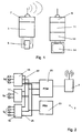
- the system includes an encoder 3 arranged in a motor vehicle, which brings signals generated by sensors 5 into a suitable form so that they can be sent by a transmitter 7.
- the system also includes a receiver 9, which receives the signals from the transmitter 7 and forwards them to a decoder 11, which decodes the sensor signals contained in the transmission signals and forwards them to a computer 13, which displays the sensor signals for display on a screen 14 and / or prepared for storage, for example on a hard disk or floppy disk.
- the sensors 5 can detect, for example, the brake pressure, the longitudinal acceleration, the lateral acceleration, the wheel speeds of all four vehicle wheels, the rotary movement of the steering wheel, the clutch pedal travel, the throttle valve position, the engine speed and the shift position of the transmission. Furthermore, a sensor can be provided which detects pylons erected on the road. Sensors can be attached to the driver, which record the pulse rate or blood pressure or other physiologically relevant values.
- the sensor data are digitized for a particularly high operational reliability of the system and are transmitted via radio link to a ground station with the receiver 9 and the further units. There they can be recorded or viewed "online”.
- each training participant and his / her supervisor can completely go through the immediately preceding journey and be informed of their errors or possible improvements on the screen 14 or by means of a printout of the screen display.
- the errors can already be evaluated "online” by trained persons on the screen and communicated to the exercising person directly by hand signals, by radio or during a stop.
- the basic function of the system is such that the sensor signals, which are usually in analog form as voltages, are converted into a digital word.
- the words of all measuring channels are put together to form a serial data stream which, if necessary, is set up and transmitted on a carrier frequency after a further conversion in order to increase the error security according to a certain modulation regulation.
- a first group of sensors 5a contains resistance bridge circuits and supplies an analog output voltage as a signal. Such sensors are used, for example, to record the brake pressure (strain gauges connected to a diaphragm) or the steering angle (travel potentiometer). This first group of sensors 5a is connected to an analog mother board 15.
- a second group of sensors 5b supplies digital signals, for example microswitches for detecting the gearshift position or reflection light barriers for detecting reflectors attached to pylons. These sensors are connected to a digital board 17.
- a third group of sensors 5c supplies the measured values to be recorded in a manner known per se in the form of signal frequencies, for example wheel speed sensors, the acceleration sensor (detuning of an oscillating circuit) or the pulse frequency sensor. These sensors 5c are connected to a further analog mother board 19.
- the mentioned boards 15, 17 and 19 and a pulse code modulation board 21 are supplied by a current or voltage supply unit 23 (PSU) with the required supply voltages +15 V, - 15 V and + 5 V, which are supplied with supply voltages of 9 V. up to 36 V.
- PSU current or voltage supply unit 23
- the input and output masses of the unit 23 are electrically isolated, so that there is no conductive connection between the motor vehicle ground and the electronics ground.
- Address bus 25 and a data bus 27 connect the boards 15, 17 and 19 to the pulse code modulation board 21.
- the transmitter 7 is controlled by the synthesizer and has an output of 250 mW in the application example.
- a change in the carrier frequency (for example 440.625 MHz) is carried out if necessary by exchanging the programmed microcontrollers.
- As an antenna a dipole with a magnetic base or fixed to the motor vehicle.
- the electrical length of the antenna is a quarter of the wavelength.
- reception and evaluation station with the receiver 9, the decoder 11, the computer 13 and the screen 14 and a storage unit, not shown, are not described in detail since they are known per se.
- a common peripheral personal computer can be used.
- the signal conditioning circuit 29 contains an instrumentation amplifier 31, which amplifies the often weak measurement signal in a strictly linear manner. Offset voltages existing in the measurement signal or arising from the amplification are suppressed dynamically (dynamic offset 33) and statically (static offset 35) in a manner known per se.
- the sensors are powered by a precise bridge supply 37, which is connected to a reference voltage source 39. Further voltages are made available by a voltage source 41.
- the output of the instrument amplifier 31 is connected to the analog motherboard 15 via a 6-pole low-pass filter.
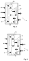
- FIG. 4 shows a frequency / voltage converter 45, as it is assigned to each of the sensors 5c, the measurement signal of which is a frequency signal which is converted into an analog voltage signal.
- a bridge supply 37 is in turn used to supply the voltage to each sensor 5c.
- the actual frequency / voltage converter unit 47 which is constructed in a manner known per se, is in turn connected to the further analog mother board 19 via a low-pass filter to suppress unwanted signals.
- Fig. 5 shows the analog motherboard 15. This board is used for measuring signal acquisition of all signal processing circuits 29.
- Each of the analog signal voltages is supplied via an 8-channel multiplexer 51 for digitization to an analog / digital converter 53, from which the digital data words via the Data bus go to the pulse code modulation board 21.
- the analog motherboard 15 can be divided into five function blocks, namely the 8-channel multiplexer 51, an impedance converter 55 connected downstream thereof, which is connected to the analog / digital converter 53, and the output switch 57 connected downstream of the converter. three states), which bring the digital words onto the system data bus, and an address and control logic which communicates with the overall control logic on the pulse code modulation board 21 and addresses modules or channels.
- the analog / digital converter 53 contains an S&H amplifier which stores the analog measured value for the duration of the digitization and suppresses changes in the signal voltage during the conversion in order to avoid errors.
- the generated digital word equivalent to the voltage value, has a width of 10 bits.
- the impedance converter 55 serves to provide the signal voltages with a very low source voltage, as a result of which the converter 55 can process them better.
- FIG. 6 shows the analog mother board 19 connected downstream of the frequency / voltage converters 45, the structure and function of which corresponds to that of the mother board 15.
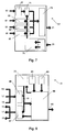
- the digital board 17 shows the digital board 17, which is used to feed a maximum of four digital 10-bit words into the PCM data stream.
- the 10-bit wide digital words go from the digital board 17 via the system data bus for further processing to the pulse code modulation board 21.
- the digital board 17 can be divided into five function blocks, namely 3 input channels 61 with 10 bits each (TTL level), one input channel 63 with 10 bits (2V ... 12 V), 4-channel multiplexer with input switches 65, 67, 69 and 71, output switch 73 (three states) and the address and control logic 75.
- a comparator 77 is connected upstream of the input switch 71, in which the inputs are queried with switching thresholds which can be set via potentiometers.
- the multiplexer with the input switches 65, 67, 69 and 71 switches all 4 digital words in the correct order to the output switches 73.
- FIG. 8 shows the pulse code modulation board 21 which supplies all modules which are used for reading in the analog and digital variables with addresses and control signals.
- the pulse code modulation board 21 receives as input a 12-bit wide parallel data stream which is converted into a serial data stream in accordance with the pulse code modulation. It contains, in a manner known per se, a memory 79 for PCM format, a reset unit 81, a clock generator 83, a data input unit 85, a unit 87 for generating the address and. Control signals, the actual PCM generator 89 and the data u. Address bus 91 and output 93 for the serial PCM data.
- the function of the pulse code modulation board 21 is known per se and is therefore not described in detail.
Abstract
Description
Die Erfindung betrifft ein System zur Auswertung der Fahrbetriebszustände eines Kraftfahrzeugs gemäß dem Obergebriff des Hauptanspruchs.The invention relates to a system for evaluating the driving operating states of a motor vehicle according to the preamble of the main claim.
Ein soches System ist aus der DE OS 31 46 711 bekannt. Dabei berechnet der Rechner eine Vielzahl von die jeweiligen Fahrbetriebszustände des Kraftfahrzeugs repräsentierenden Werten auf Basis der Ausgangssignale der Sensoren und führt eine Steuerung zur Erzeugung eines Warnsignals durch, wenn einer der Werte einem aus einer Vielzahl vorgegebener Sollwerte entspricht. Der Akkumulationswert der Warnsignale und die Gründe für die Warnsignale werden in einer externen Speichereinheit abgespeichert, die nach Fahrtende demontiert wird. Auf diese Weise läßt sich das Fahrverhalten des Fahrers im Nachhinein ermitteln und nötigenfalls korrigieren.Such a system is known from DE OS 31 46 711. The computer calculates a large number of values representing the respective driving operating states of the motor vehicle on the basis of the output signals from the sensors and carries out a control for generating a warning signal if one of the values corresponds to one of a large number of predefined target values. The accumulation value of the warning signals and the reasons for the warning signals are stored in an external storage unit which is dismantled after the end of the journey. In this way, the driver's driving behavior can be determined afterwards and corrected if necessary.
Aus der DE OS 27 28 362 ist ein Datenverarbeitungssystem für Fahrdaten insbesondere von Schienenfahrzeugen bekannt, bei dem die im Fahrzeug aufgezeichneten Fahrdaten an ein vom Fahrzeug entferntes Speichermedium gegeben werden, in dem sie umgewandelt werden. Die umgewandelten Daten werden in einen Rechner eingegeben und dort mit ein bekanntes Leistungsprofil darstellenden Stammdaten unter Steuerung eines Programms zur Ableitung analytischer Ergebnisse hinsichtlich der Fahrleistung verglichen. Die Aufzeichnung der Fahrdaten erfolgt mittels versiegelter Patronen, die ein Endlosband enthalten und beispielsweise in eine Aufzeichnungseinheit an Bord einer Lokomotive eingesteckt werden. Die Patrone wird nach Aufzeichnung der Information aus der Lokomotive herausgenommen und in eine Wiedergabeeinheit eingesteckt.A data processing system for driving data, in particular of rail vehicles, is known from DE OS 27 28 362, in which the driving data recorded in the vehicle are given to a storage medium remote from the vehicle, in which they are converted. The converted data are entered into a computer and compared there with master data representing a known performance profile under the control of a program for deriving analytical results with regard to driving performance. The driving data is recorded using sealed cartridges, which contain an endless belt and are inserted, for example, into a recording unit on board a locomotive. After the information has been recorded, the cartridge is removed from the locomotive and inserted into a playback unit.
In neuerer Zeit kommt zur Unfallvorbeugung der Fahrerausbildung steigende Bedeutung zu. Viele Firmen, Automobilclubs und öffentliche Einrichtungen haben Fahr-und Sicherheitskurse eingerichtet, in denen, getrennt vom öffentlichen Verkehr, kritische Fahrsituationen geübt werden können, so daß diese dann in der Praxis, wo man häufig ungewollt mit solchen Situationen konfrontiert ist, besser beherrscht werden. Ein wichtiger Bestandteil solcher Trainingkurse liegt darin, mit dem Fahrer/der Fahrerin die durchfahrenen Situationen diskutieren zu können, um gegebenenfalls auf Fehler oder Verbesserungsmöglichkeiten aufmerksam machen zu können. Dies soll in möglichst enger zeitlicher Folge mit den durchfahrenen Situationen und möglichst realistisch geschehen, da dadurch der Lerneffekt positiv beeinflußt wird. Bekannte Systeme haben den Nachteil, daß der an Bord des Fahrzeugs befindliche Datenspeicher nach Fahrtbeendigung entnommen und zur Auswertung in ein Auswertegerät gebracht werden muß. Dadurch geht wertvolle Zeit verloren und ist eine Instruktion des Fahrers/der Fahrerin bereits während der Fahrt nicht möglich.In recent times, driver training has become increasingly important in preventing accidents. Many companies, automobile clubs and public institutions have set up driving and safety courses in which critical driving situations can be practiced separately from public transport, so that they can be better mastered in practice where such situations are often unintentionally confronted. An important part of such training courses is to be able to discuss the situations that have been driven through with the driver, in order to be able to draw attention to any errors or opportunities for improvement. This is said in Happen as closely as possible in time with the situations you have traveled through and as realistically as possible, as this has a positive effect on the learning effect. Known systems have the disadvantage that the data storage located on board the vehicle must be removed after the end of the journey and brought into an evaluation device for evaluation. As a result, valuable time is lost and the driver cannot be instructed while driving.
Der Erfindung liegt die Aufgabe zugrunde, ein insbesondere für die Anwendung bei Fahr- und Sicherheitstrainings geeignetes System zur Auswertung der Fahrbetriebsweise eines Kraftfahrzeugs zu schaffen, welches eine effiziente Schulung der Fahrer/Fahrerinnen gestattet.The invention has for its object to provide a system, which is particularly suitable for use in driving and safety training, for evaluating the driving mode of operation of a motor vehicle and which permits efficient training of the drivers.
Diese Aufgabe wird bei einem gattungsgemäßen System zur Auswertung der Fahrbetriebsweise eines Kraftfahrzeugs mit den kennzeichnenden Merkmalen des Hauptanspruchs gelöst.This object is achieved in a generic system for evaluating the driving mode of operation of a motor vehicle with the characterizing features of the main claim.
Dadurch, daß bei dem erfindungsgemäßen System die Sensorsignale bereits während der Fahrt des Fahrzeugs an einen vom Fahrzeug getrennten Empfänger gesendet werden, der ortsfest oder in einem Begleitfahrzeug untergebracht sein kann, und dort unmittelbar "online" oder im Nachhinein ausgewertet werden können, ist eine sofortige zielgerichtete Instruktion des Fahrers/der Fahrerin möglich, bereits während der Fahrt durch Handzeichen, durch Funkanweisungen oder unmittelbar nach der Fahrt, wo das Erinnerungsvermögen des gerade Gefahrenen noch frisch ist.The fact that in the system according to the invention the sensor signals are already sent while the vehicle is traveling to a receiver separate from the vehicle, which can be stationary or in an escort vehicle, and can be evaluated there directly "online" or afterwards, is an immediate one Targeted instruction of the driver possible, already during the journey by hand signals, by radio instructions or immediately after the journey, where the memory of the person just driven is still fresh.
Mit den Merkmalen des Anspruchs 2 wird erreicht, daß die Fahrzeugbetriebsdaten unmittelbar der jeweiligen Streckenposition zugeordnet werden können, was für die Schulung besonders vorteilhaft ist, da die jeweilige Situation komplett nachvollzogen und Fehler entsprechend analysiert werden können.With the features of claim 2 it is achieved that the vehicle operating data can be assigned directly to the respective route position, which is particularly advantageous for the training, since the respective situation can be fully understood and errors can be analyzed accordingly.
Mit den Merkmalen des Anspuchs 3 wird erreicht, daß sich den jeweiligen Situationen zusätzlich medizinisch relevante Daten des Fahrers/der Fahrerin des Kraftfahrzeugs zuordnen lassen, was sowohl für die Erklärung bestimmter Verhaltensweisen alsauch generell für Aussagen über den Zustand und die Belastungsfähigkeit des Fahrers/der Fahrerin wichtig ist.With the features of
Selbstverständlich können auch bei dem erfindungsgemäßen System Einrichtungen vorgesehen sein, die in bestimmten Situationen Warnsignale erzeugen, beispielsweise, wenn zu stark gebremst wird, wenn ein Geschwindigkeitslimit überschritten wird oder wenn eine bestimmte Pulsfrequenz oder ein Blutdruck überschritten wird.Of course, devices can also be provided in the system according to the invention which generate warning signals in certain situations, for example when braking too hard, when a speed limit is exceeded or when a certain pulse rate or blood pressure is exceeded.
Die Erfindung wird im folgenden anhand schematischer Zeichnungen beispielsweise und mit weiteren Einzelheiten erläutert. Alle Figuren stellen Blockschaltbilder dar und zwar
- Fig 1 das Gesamtsystem.
- Fig. 2 den Encoder ,
- Fig. 3 die Signalaufbereitungseinrichtung,
- Fig. 4 einen Frequenz-/Spannungswandler,
- Fig 5 ein analoges Mutterbord,
- Fig. 6 ein weiteres analoges Mutterbord,
- Fig. 7 ein Digitalbord und
- Fig. 8 ein Pulscodemodulationsbord.
- 1 shows the overall system.
- 2 the encoder,
- 3 shows the signal processing device,
- 4 shows a frequency / voltage converter,
- 5 an analog motherboard,
- 6 shows another analog motherboard,
- Fig. 7 is a digital board and
- 8 shows a pulse code modulation board.
Gemäß Fig. 1 gehört zum System ein in einem Kraftfahrzeug angeordneter Encoder 3, der von Sensoren 5 erzeugte Signale in geeignete Form bringt, damit diese von einem Sender 7 gesendet werden können. Weiter gehört im dargestellten Beispiel zum System ein Empfänger 9, der die Signale des Senders 7 empfängt und an einen Decoder 11 weiterleitet, welcher die in den Sendesignalen enthaltenen Sensorsignale decodiert und an einen Rechner 13 weiterleitet, welcher die Sensorsignale zur Anzeige durch einen Bildschirm 14 und/oder zur Speicherung beispielsweise auf Festplatte oder Diskette aufbereitet.According to FIG. 1, the system includes an
Die Sensoren 5 können beispielsweise den Bremsdruck, die Längsbeschleunigung, die Querbeschleunigung, die Raddrehzahlen aller vier Fahrzeugräder, die Drehbewegung des Lenkrades, den Kupplungspedalweg, die Drosselklappenstellung, die Motordrehzahl und die Schaltstellung des Getriebes erfassen. Weiter kann ein Sensor vorgesehen sein, welcher an der Fahrbahn aufgestellte Pylonen erkennt. Am Fahrer bzw. der Fahrerin können Sensoren angebracht sein, welche die Pulsfrequenz oder den Blutdruck oder sonstwelche physiologisch relevanten Werte erfassen.The
Die Sensordaten werden für eine besonders hohe Betriebssicherheit des Systems digitalisiert und per Funkstrecke an eine Bodenstation mit dem Empfänger 9 und den weiteren Einheiten geleitet. Dort können sie aufgezeichnet oder "online" betrachtet werden.The sensor data are digitized for a particularly high operational reliability of the system and are transmitted via radio link to a ground station with the
Nach dem Abfahren der Teststrecke kann jeder Trainingsteilnehmer mit seinem Betreuer die unmittelbar vorhergegangene Fahrt komplett durchgehen und auf dem Bildschirm14 oder an Hand eines Ausdruckes der Bildschirmdarstellung auf seine Fehler bzw. Verbesserungsmöglichkeiten hingewiesen werden.After the test route has been traveled, each training participant and his / her supervisor can completely go through the immediately preceding journey and be informed of their errors or possible improvements on the
Bei längeren Trainingsfahrten können die Fehler auch bereits "online" durch geschulte Personen am Bildschirm ausgewertet und dem Trainierenden unmittelbar durch Handzeichen, per Funk oder während eines Stops mitgeteilt werden.During longer training trips, the errors can already be evaluated "online" by trained persons on the screen and communicated to the exercising person directly by hand signals, by radio or during a stop.
Die Grundfunktion des Systems ist derart, daß die meist in analoger Form als Spannungen vorliegenden Sensorsignale in ein digitales Wort gewandelt werden. Die Worte aller Meßkanäle werden zu einem seriellen Datenstrom zusammengestellt, der ggfs. nach nochmaliger Umwandlung zur Erhöhung der Fehlersicherheit nach einer bestimmten Modulationsvorschrift auf eine Trägerfrequenz aufgesetzt und gesendet wird.The basic function of the system is such that the sensor signals, which are usually in analog form as voltages, are converted into a digital word. The words of all measuring channels are put together to form a serial data stream which, if necessary, is set up and transmitted on a carrier frequency after a further conversion in order to increase the error security according to a certain modulation regulation.
Fig. 2 zeigt den Encoder 3.2 shows the
Entsprechend den unterschiedlichen zu erfassenden Werten haben die Sensoren unterschiedliche Ausgangssignale. Eine erste Gruppe von Sensoren 5a enthält Widerstandsbrückenschaltungen und liefert als Signal eine analoge Ausgangsspannung. Solche Sensoren dienen beispielsweise zur Erfassung des Bremsdruckes (an eine Membran angeschlossener Dehnungsmeßstreifen) oder des Lenkwinkels (Wegepotentiometer). Diese erste Gruppe von Sensoren 5a ist an ein analoges Mutterbord 15 angeschlossen.Depending on the different values to be recorded, the sensors have different output signals. A first group of
Eine zweite Gruppe von Sensoren 5b liefert digitale Signale, beispielsweise Mikroschalter zur Erkennung der Schaltstellung des Getriebes oder Reflexionslichtschranken zur Erkennung von an Pylonen angebrachten Reflektoren. Diese Sensoren sind an ein Digitalbord 17 angeschlossen.A second group of
Eine dritte Gruppe von Sensoren 5c liefert die zu erfassenden Meßwerte in an sich bekannter Weise in Form von Signalfrequenzen, beispielsweise Raddrehzahlsensoren , der Beschleunigungssensor ( Verstimmung eines Schwingkreises) oder der Pulsfrequenzsensor. Diese Sensoren 5c sind an ein weiteres analoges Mutterbord 19 angeschlossen.A third group of
Die genannten Bords 15,17 und 19 sowie ein Pulscodemodulationsbord 21 (PCM) werden von einer Strom-bzw.Spannungsversorgungseinheit 23 (PSU) mit den benötigten Versorgungsspannungen +15 V, - 15 V und + 5 V versorgt, die bei Speisespannungen von 9 V bis 36 V erzeugt werden. Eingangs- und Ausgangsmasse der Einheit 23 sind galvanisch getrennt, sodaß keine leitende Verbindung zwischen der Kraftfahrzeug-Masse und der Elektronik-Masse besteht. Adressbus 25 und ein Datenbus 27 verbinden die Bords 15, 17 und 19 mit dem Pulscodemodulationsbord 21.The mentioned
Der Sender 7 ist sythesizergesteuert und hat im Anwendungsbeispiel eine Leistung von 250 mW. Eine Änderung der Trägerfrequenz (beispielsweise 440,625 MHz) erfogt erforderlichenfalls durch Austausch der programmierten Microcontroller. Als Antenne wird ein Dipol mit Magnetfuß oder fest am Kraftfahrzeug befestigt. Die elektrische Länge der Antenne beträgt ein Viertel der Wellenlänge.The
Die Empfangs- und Auswertestation mit dem Empfänger 9, dem Decoder 11, dem Rechner 13 und dem Bildschirm 14 sowie einer nicht dargestellten Speichereinheit werden im einzelnen nicht beschrieben, da an sich bekannt. Es kann ein üblicher Personalcomputer mit Peripherie verwendet werden.The reception and evaluation station with the
Fig.3 zeigt eine Signalaufbereitungsschaltung 29 , wie sie jedem der Sensoren 5a zugeordnet ist. Die Aufgabe der Signalaufbereitungsschaltung 29 besteht darin, die Signale der Sensoren 5a so aufzubereiten, daß diese anschließend problemlos digitalisiert werden können. Dazu enthält die Signalaufbereitungsschaltung 29 einen Instrumentierungsverstärker 31, welcher das häufig schwache Meßsignal streng linear verstärkt. Im Meßsignal bestehende oder durch die Verstärkung entstehende Offset Spannungen werden in an sich bekannter Weise dynamisch (dynamischer Offset 33) und statisch (statischer Offset 35) unterdrückt. Die Spannungsversorgung der Sensoren erfolgt mittels einer präzisen Brückenversorgung 37, welche an eine Referenzspannungsquelle 39 angeschlossen ist. Weitere Spannungen werden von einer Spannungsquelle 41 zur Verfügung gestellt. Um unerwünschte hochfrequente Signalanteile zu unterdrücken, ist der Ausgang des Instrumentenverstärkers 31 über ein 6-poliges Tiefpaßfilter mit dem analogen Mutterbord 15 verbunden.3 shows a
Fig. 4 zeigt einen Frequenz-/Spannungswandler 45, wie er jedem der Sensoren 5c zugeordnet ist, deren Meßsignal ein Frequenzsignal ist, welches in ein analoges Spannungssignal umgewandelt wird. Zur Spannungsver-sorgung jedes Sensors 5c dient wiederum eine Brückenversorgung 37. Die eigentliche, wie an sich bekannt aufgebaute Frequenz-/Spannungs-wandlereinheit 47 ist zur Unterdrückung unerwünschter Signale wiederum über ein Tiefpaßfilter mit dem weiteren analogen Muterbord 19 verbunden.FIG. 4 shows a frequency /
Fig. 5 zeigt das analoge Mutterbord 15. Dieses Bord dient der Meßsignalerfassung aller Signalaufbereitungsschaltungen 29. Jede der analogen Signalspannungen wird über einen 8-Kanal Multiplexer 51 zur Digitalisierung an einen Analog/Digital Wandler 53 geliefert., von dem aus die digitalen Datenwörter über den Datenbus an das Pulscodemodulationsbord 21 gehen. Die Fg. 5 zeigt deutlich, daß das analoge Mutterbord 15 in fünf Funktionsblöcke unterteilt werden kann, nämlich den 8-Kanalmultiplexer 51, einen diesem nachgeschalteten Impedanzwandler 55, der mit dem Analog/Digital Wandler 53 verbunden ist, sowie dem Wandler nachgeschaltet Ausgangsschalter 57 (drei Zustände), die die Digitalwörter auf den Systemdatenbus bringen, und eine Adreß-und Steuerlogik, die mit der Gesamtsteuerlogik auf dem Pulscodemodulationsbord 21 kommuniziert und Module bzw.Kanäle adressiert. Der Analog/Digital Wandler 53 enthält einen S&H Verstärker, der den analogen Meßwert für die Dauer der Digitalisierung speichert und zur Fehlervermeidung Änderungen der Signalspannung während der Wandlung unterdrückt. Das generierte, dem Spannungswert äquivalente Digitalwort hat eine Breite von 10 Bits. Der Impedanzwandler 55 dient dazu, die Signalspannungen mit einer sehr niedrigen Quellenspannung zu versehen, wodurch sie vom Wandler 55 besser verarbeitet werden können.Fig. 5 shows the
Fig.6 zeigt das den Frequenz-/Spannungswandlern 45 nachgeschaltete analoge Mutterbord 19, dessen Aufbau und Funktion dem bzw. der des Mutterbordes 15 entspricht.6 shows the
Fig. 7 zeigt das Digitalbord 17, welches zur Einspeisung von maximal vier digitalen 10-Bit Wörtern in den PCM-Datenstrom dient. Vom Digitalbord 17 gehen die 10-Bit breiten Digitalwörter über den Systemdatenbus zur Weiterverarbeitung an das Pulscodemodulationsbord 21. Das Digitalbord 17 kann in fünf Funktionsblöcke unterteilt werden, nämlich 3 Eingangskanäle 61 mit je 10 Bit (TTL-Pegel), ein Eingangskanal 63 mit 10 Bit (2V ... 12 V), 4-Kanal-Multiplexer mit Eingangsschaltern 65, 67, 69 und 71, Ausgangsschalter 73 (drei Zustände) sowie der Adreß-und Steuerlogik 75.7 shows the
Im digitalen Eingang 63 mit 10 Bit Wortbreite für Daten mit einem Spannungspegel zwischen 2V und 12V ist dem Eingangsschalter 71 ein Komparator 77 vorgeschaltet, in dem die Eingänge mit über Potentiometer einstellbaren Schaltschwellen abgefragt werden. Der Multiplexer mit den Eingangsschaltern 65, 67, 69 und 71 schaltet alle 4 Digitalwörter in der richtigen Reihenfolge zu den Ausgangsschaltern 73.In the
Fig. 8 zeigt das Pulscodemodulationsbord 21, das sämtliche Module, die zum Einlesen der analogen und digitalen Größen dienen, mit Adressen und Steuersignalen versorgt. Als Input erhält das Pulscodemudulationsbord 21 einen 12 Bit breiten parallelen Datenstrom, der entsprechend der Puls Code Modulation in einen seriellen Datenstrom gewandelt werden. Es enthält in an sich bekannter Weise einen Speicher 79 für PCM Format, eine Reset-Einheit 81, einen Taktgeber 83, eine Dateneingangseinheit 85, eine Einheit 87 zum Erzeugen der Adreß-u. Steuersignale, den eigentlichen PCM-Generator 89 sowie den Daten-u. Adress Bus 91 und den Ausgang 93 für die seriellen PCM Daten. Die Funktion des Pulcodemodulationsbordes 21 ist wie an sich bekannt und wird daher nicht näher beschrieben.FIG. 8 shows the pulse
Claims (3)
einen an die Sensoren(5; 5a, 5b, 5c ) angeschlossenen Encoder(3), welcher die Sensorsignale in einen seriellen Datenstrom wandelt, einen dem Encoder (3) nachgeschalteten Sender(7), welcher den seriellen Datenstrom an einen vom Fahrzeug getrennten Empfänger(9) sendet, und einen dem Empfänger(9) nachgeschalteten Decoder(11), welcher aus dem seriellen Datenstrom die Sensorsignale rekonstruiert und an die Auswerteeinheit(13,14) angeschlossen ist.System for evaluating the driving mode of operation of a motor vehicle, with sensors arranged in the motor vehicle for determining driving operating states of the motor vehicle and an evaluation unit with a computer which reads out the driving operating state signals derived from the sensor signals and feeds them to a memory and / or a display unit, characterized by
an encoder (3) connected to the sensors (5; 5a, 5b, 5c), which converts the sensor signals into a serial data stream, a transmitter (7) connected downstream of the encoder (3), which sends the serial data stream to a receiver separate from the vehicle (9) sends, and a decoder (11) connected downstream of the receiver (9) which reconstructs the sensor signals from the serial data stream and is connected to the evaluation unit (13, 14).
Applications Claiming Priority (2)
| Application Number | Priority Date | Filing Date | Title |
|---|---|---|---|
| DE4322327 | 1993-07-05 | ||
| DE4322327 | 1993-07-05 |
Publications (2)
| Publication Number | Publication Date |
|---|---|
| EP0633552A2 true EP0633552A2 (en) | 1995-01-11 |
| EP0633552A3 EP0633552A3 (en) | 1996-03-13 |
Family
ID=6491994
Family Applications (1)
| Application Number | Title | Priority Date | Filing Date |
|---|---|---|---|
| EP94109714A Withdrawn EP0633552A3 (en) | 1993-07-05 | 1994-06-23 | Vehicle driving style evaluation system. |
Country Status (1)
| Country | Link |
|---|---|
| EP (1) | EP0633552A3 (en) |
Cited By (33)
| Publication number | Priority date | Publication date | Assignee | Title |
|---|---|---|---|---|
| WO2000031712A1 (en) * | 1998-11-26 | 2000-06-02 | Greger Andersson | Method to decide the handling pattern of the controls for a driver |
| US6603872B2 (en) | 1996-05-13 | 2003-08-05 | Cummins-Allison Corp. | Automated document processing system using full image scanning |
| EP1521219A1 (en) * | 2003-10-01 | 2005-04-06 | Centre National Du Machinisme Agricole, Du Genie Rural, Des Eaux Et Des Forets (Cemagref) | Device for data transmission from at least a sensor located on a vehicle such as an agricultural machine |
| US7778456B2 (en) | 1995-05-02 | 2010-08-17 | Cummins-Allison, Corp. | Automatic currency processing system having ticket redemption module |
| US7881519B2 (en) | 2001-09-27 | 2011-02-01 | Cummins-Allison Corp. | Document processing system using full image scanning |
| US7903863B2 (en) | 2001-09-27 | 2011-03-08 | Cummins-Allison Corp. | Currency bill tracking system |
| US7980378B2 (en) | 2006-03-23 | 2011-07-19 | Cummins-Allison Corporation | Systems, apparatus, and methods for currency processing control and redemption |
| US8126793B2 (en) | 2001-07-05 | 2012-02-28 | Cummins-Allison Corp. | Automated payment system and method |
| US8162125B1 (en) | 1996-05-29 | 2012-04-24 | Cummins-Allison Corp. | Apparatus and system for imaging currency bills and financial documents and method for using the same |
| US8169602B2 (en) | 1996-11-27 | 2012-05-01 | Cummins-Allison Corp. | Automated document processing system and method |
| US8204293B2 (en) | 2007-03-09 | 2012-06-19 | Cummins-Allison Corp. | Document imaging and processing system |
| US8391583B1 (en) | 2009-04-15 | 2013-03-05 | Cummins-Allison Corp. | Apparatus and system for imaging currency bills and financial documents and method for using the same |
| US8417017B1 (en) | 2007-03-09 | 2013-04-09 | Cummins-Allison Corp. | Apparatus and system for imaging currency bills and financial documents and method for using the same |
| US8428332B1 (en) | 2001-09-27 | 2013-04-23 | Cummins-Allison Corp. | Apparatus and system for imaging currency bills and financial documents and method for using the same |
| US8433123B1 (en) | 2001-09-27 | 2013-04-30 | Cummins-Allison Corp. | Apparatus and system for imaging currency bills and financial documents and method for using the same |
| US8437530B1 (en) | 2001-09-27 | 2013-05-07 | Cummins-Allison Corp. | Apparatus and system for imaging currency bills and financial documents and method for using the same |
| US8437528B1 (en) | 2009-04-15 | 2013-05-07 | Cummins-Allison Corp. | Apparatus and system for imaging currency bills and financial documents and method for using the same |
| US8437529B1 (en) | 2001-09-27 | 2013-05-07 | Cummins-Allison Corp. | Apparatus and system for imaging currency bills and financial documents and method for using the same |
| USRE44252E1 (en) | 2002-01-10 | 2013-06-04 | Cummins-Allison Corp. | Coin redemption system |
| US8459436B2 (en) | 2008-10-29 | 2013-06-11 | Cummins-Allison Corp. | System and method for processing currency bills and tickets |
| US8478020B1 (en) | 1996-11-27 | 2013-07-02 | Cummins-Allison Corp. | Apparatus and system for imaging currency bills and financial documents and method for using the same |
| US8538123B1 (en) | 2007-03-09 | 2013-09-17 | Cummins-Allison Corp. | Apparatus and system for imaging currency bills and financial documents and method for using the same |
| US8595034B2 (en) | 1996-01-29 | 2013-11-26 | Progressive Casualty Insurance Company | Monitoring system for determining and communicating a cost of insurance |
| US8627939B1 (en) | 2002-09-25 | 2014-01-14 | Cummins-Allison Corp. | Apparatus and system for imaging currency bills and financial documents and method for using the same |
| CN103617755A (en) * | 2013-12-17 | 2014-03-05 | 浙江维尔科技股份有限公司 | Test result generation unit and device |
| US8892451B2 (en) | 1996-01-29 | 2014-11-18 | Progressive Casualty Insurance Company | Vehicle monitoring system |
| US8929640B1 (en) | 2009-04-15 | 2015-01-06 | Cummins-Allison Corp. | Apparatus and system for imaging currency bills and financial documents and method for using the same |
| US8944234B1 (en) | 2001-09-27 | 2015-02-03 | Cummins-Allison Corp. | Apparatus and system for imaging currency bills and financial documents and method for using the same |
| US9141876B1 (en) | 2013-02-22 | 2015-09-22 | Cummins-Allison Corp. | Apparatus and system for processing currency bills and financial documents and method for using the same |
| CN105631966A (en) * | 2014-12-01 | 2016-06-01 | 中车大连电力牵引研发中心有限公司 | Rail train convertor equipment data recording device |
| CN106781820A (en) * | 2016-12-02 | 2017-05-31 | 上海谷福实业发展有限公司 | Vehicle driver intellectuality outdoor scene examination system |
| US9818249B1 (en) | 2002-09-04 | 2017-11-14 | Copilot Ventures Fund Iii Llc | Authentication method and system |
| US11030702B1 (en) | 2012-02-02 | 2021-06-08 | Progressive Casualty Insurance Company | Mobile insurance platform system |
Families Citing this family (2)
| Publication number | Priority date | Publication date | Assignee | Title |
|---|---|---|---|---|
| US8950566B2 (en) | 1996-05-13 | 2015-02-10 | Cummins Allison Corp. | Apparatus, system and method for coin exchange |
| US7929749B1 (en) | 2006-09-25 | 2011-04-19 | Cummins-Allison Corp. | System and method for saving statistical data of currency bills in a currency processing device |
Citations (6)
| Publication number | Priority date | Publication date | Assignee | Title |
|---|---|---|---|---|
| FR2438877A1 (en) * | 1978-10-10 | 1980-05-09 | Baranoff Dimitri | Centralise control and monitoring system for service vehicle - uses data transmission from vehicle of position and condition sensor outputs with data transferred to storage unit |
| GB2150725A (en) * | 1983-11-30 | 1985-07-03 | Aisin Seiki | Safety apparatus for a road vehicle |
| EP0290364A1 (en) * | 1987-04-29 | 1988-11-09 | Sarl France Pilotage Systemes | Apparatus for learning how to drive a car |
| DE3805810A1 (en) * | 1988-02-24 | 1989-09-07 | Amend Volker | Communication system for vehicles |
| FR2667962A1 (en) * | 1990-10-11 | 1992-04-17 | Opti Pilote | Method of recording and processing data for managing the driving of vehicles |
| WO1993004353A1 (en) * | 1991-08-12 | 1993-03-04 | Crane Harold E | Interactive dynamic realtime management system for powered vehicles |
-
1994
- 1994-06-23 EP EP94109714A patent/EP0633552A3/en not_active Withdrawn
Patent Citations (6)
| Publication number | Priority date | Publication date | Assignee | Title |
|---|---|---|---|---|
| FR2438877A1 (en) * | 1978-10-10 | 1980-05-09 | Baranoff Dimitri | Centralise control and monitoring system for service vehicle - uses data transmission from vehicle of position and condition sensor outputs with data transferred to storage unit |
| GB2150725A (en) * | 1983-11-30 | 1985-07-03 | Aisin Seiki | Safety apparatus for a road vehicle |
| EP0290364A1 (en) * | 1987-04-29 | 1988-11-09 | Sarl France Pilotage Systemes | Apparatus for learning how to drive a car |
| DE3805810A1 (en) * | 1988-02-24 | 1989-09-07 | Amend Volker | Communication system for vehicles |
| FR2667962A1 (en) * | 1990-10-11 | 1992-04-17 | Opti Pilote | Method of recording and processing data for managing the driving of vehicles |
| WO1993004353A1 (en) * | 1991-08-12 | 1993-03-04 | Crane Harold E | Interactive dynamic realtime management system for powered vehicles |
Non-Patent Citations (1)
| Title |
|---|
| PROCEEDINGS IECON '84; INDUSTRIAL APPLICATIONS OF MICROELECTRONICS, Bd. 1, 22. - 26.Oktober 1984 TOKYO JAPAN , Seiten 318-323, TSUGAWA 'Computer-aided instruction system of automobile driving' * |
Cited By (85)
| Publication number | Priority date | Publication date | Assignee | Title |
|---|---|---|---|---|
| US7778456B2 (en) | 1995-05-02 | 2010-08-17 | Cummins-Allison, Corp. | Automatic currency processing system having ticket redemption module |
| US8595034B2 (en) | 1996-01-29 | 2013-11-26 | Progressive Casualty Insurance Company | Monitoring system for determining and communicating a cost of insurance |
| US9754424B2 (en) | 1996-01-29 | 2017-09-05 | Progressive Casualty Insurance Company | Vehicle monitoring system |
| US8892451B2 (en) | 1996-01-29 | 2014-11-18 | Progressive Casualty Insurance Company | Vehicle monitoring system |
| US6678401B2 (en) | 1996-05-13 | 2004-01-13 | Cummins-Allison Corp. | Automated currency processing system |
| US6665431B2 (en) | 1996-05-13 | 2003-12-16 | Cummins-Allison Corp. | Automated document processing system using full image scanning |
| US6678402B2 (en) | 1996-05-13 | 2004-01-13 | Cummins-Allison Corp. | Automated document processing system using full image scanning |
| US6603872B2 (en) | 1996-05-13 | 2003-08-05 | Cummins-Allison Corp. | Automated document processing system using full image scanning |
| US6724927B2 (en) | 1996-05-13 | 2004-04-20 | Cummins-Allison Corp. | Automated document processing system with document imaging and value indication |
| US6724926B2 (en) | 1996-05-13 | 2004-04-20 | Cummins-Allison Corp. | Networked automated document processing system and method |
| US6731786B2 (en) | 1996-05-13 | 2004-05-04 | Cummins-Allison Corp. | Document processing method and system |
| US6810137B2 (en) | 1996-05-13 | 2004-10-26 | Cummins-Allison Corp. | Automated document processing system and method |
| US6654486B2 (en) | 1996-05-13 | 2003-11-25 | Cummins-Allison Corp. | Automated document processing system |
| US6647136B2 (en) | 1996-05-13 | 2003-11-11 | Cummins-Allison Corp. | Automated check processing system and method |
| US6650767B2 (en) | 1996-05-13 | 2003-11-18 | Cummins-Allison, Corp. | Automated deposit processing system and method |
| US8714336B2 (en) | 1996-05-29 | 2014-05-06 | Cummins-Allison Corp. | Apparatus and system for imaging currency bills and financial documents and method for using the same |
| US8162125B1 (en) | 1996-05-29 | 2012-04-24 | Cummins-Allison Corp. | Apparatus and system for imaging currency bills and financial documents and method for using the same |
| US8478020B1 (en) | 1996-11-27 | 2013-07-02 | Cummins-Allison Corp. | Apparatus and system for imaging currency bills and financial documents and method for using the same |
| US8169602B2 (en) | 1996-11-27 | 2012-05-01 | Cummins-Allison Corp. | Automated document processing system and method |
| US8442296B2 (en) | 1996-11-27 | 2013-05-14 | Cummins-Allison Corp. | Check and U.S. bank note processing device and method |
| US8339589B2 (en) | 1996-11-27 | 2012-12-25 | Cummins-Allison Corp. | Check and U.S. bank note processing device and method |
| US9390574B2 (en) | 1996-11-27 | 2016-07-12 | Cummins-Allison Corp. | Document processing system |
| US8437531B2 (en) | 1996-11-27 | 2013-05-07 | Cummins-Allison Corp. | Check and U.S. bank note processing device and method |
| WO2000031712A1 (en) * | 1998-11-26 | 2000-06-02 | Greger Andersson | Method to decide the handling pattern of the controls for a driver |
| US8701857B2 (en) | 2000-02-11 | 2014-04-22 | Cummins-Allison Corp. | System and method for processing currency bills and tickets |
| US9129271B2 (en) | 2000-02-11 | 2015-09-08 | Cummins-Allison Corp. | System and method for processing casino tickets |
| US9495808B2 (en) | 2000-02-11 | 2016-11-15 | Cummins-Allison Corp. | System and method for processing casino tickets |
| US8126793B2 (en) | 2001-07-05 | 2012-02-28 | Cummins-Allison Corp. | Automated payment system and method |
| US9142075B1 (en) | 2001-09-27 | 2015-09-22 | Cummins-Allison Corp. | Apparatus and system for imaging currency bills and financial documents and method for using the same |
| US8944234B1 (en) | 2001-09-27 | 2015-02-03 | Cummins-Allison Corp. | Apparatus and system for imaging currency bills and financial documents and method for using the same |
| US8437530B1 (en) | 2001-09-27 | 2013-05-07 | Cummins-Allison Corp. | Apparatus and system for imaging currency bills and financial documents and method for using the same |
| US8428332B1 (en) | 2001-09-27 | 2013-04-23 | Cummins-Allison Corp. | Apparatus and system for imaging currency bills and financial documents and method for using the same |
| US8655045B2 (en) | 2001-09-27 | 2014-02-18 | Cummins-Allison Corp. | System and method for processing a deposit transaction |
| US8396278B2 (en) | 2001-09-27 | 2013-03-12 | Cummins-Allison Corp. | Document processing system using full image scanning |
| US8437529B1 (en) | 2001-09-27 | 2013-05-07 | Cummins-Allison Corp. | Apparatus and system for imaging currency bills and financial documents and method for using the same |
| US8644584B1 (en) | 2001-09-27 | 2014-02-04 | Cummins-Allison Corp. | Apparatus and system for imaging currency bills and financial documents and method for using the same |
| US8639015B1 (en) | 2001-09-27 | 2014-01-28 | Cummins-Allison Corp. | Apparatus and system for imaging currency bills and financial documents and method for using the same |
| US8644585B1 (en) | 2001-09-27 | 2014-02-04 | Cummins-Allison Corp. | Apparatus and system for imaging currency bills and financial documents and method for using the same |
| US8103084B2 (en) | 2001-09-27 | 2012-01-24 | Cummins-Allison Corp. | Document processing system using full image scanning |
| US8433123B1 (en) | 2001-09-27 | 2013-04-30 | Cummins-Allison Corp. | Apparatus and system for imaging currency bills and financial documents and method for using the same |
| US8041098B2 (en) | 2001-09-27 | 2011-10-18 | Cummins-Allison Corp. | Document processing system using full image scanning |
| US8655046B1 (en) | 2001-09-27 | 2014-02-18 | Cummins-Allison Corp. | Apparatus and system for imaging currency bills and financial documents and method for using the same |
| US7903863B2 (en) | 2001-09-27 | 2011-03-08 | Cummins-Allison Corp. | Currency bill tracking system |
| US7881519B2 (en) | 2001-09-27 | 2011-02-01 | Cummins-Allison Corp. | Document processing system using full image scanning |
| USRE44252E1 (en) | 2002-01-10 | 2013-06-04 | Cummins-Allison Corp. | Coin redemption system |
| US9818249B1 (en) | 2002-09-04 | 2017-11-14 | Copilot Ventures Fund Iii Llc | Authentication method and system |
| US8627939B1 (en) | 2002-09-25 | 2014-01-14 | Cummins-Allison Corp. | Apparatus and system for imaging currency bills and financial documents and method for using the same |
| US9355295B1 (en) | 2002-09-25 | 2016-05-31 | Cummins-Allison Corp. | Apparatus and system for imaging currency bills and financial documents and method for using the same |
| FR2860620A1 (en) * | 2003-10-01 | 2005-04-08 | Centre Nat Machinisme Agricole | DEVICE FOR TRANSMITTING INFORMATION FROM AT LEAST ONE PLACE SENSOR ON VEHICLE SUCH AS AN AGRICULTURAL MACHINE |
| EP1521219A1 (en) * | 2003-10-01 | 2005-04-06 | Centre National Du Machinisme Agricole, Du Genie Rural, Des Eaux Et Des Forets (Cemagref) | Device for data transmission from at least a sensor located on a vehicle such as an agricultural machine |
| US7980378B2 (en) | 2006-03-23 | 2011-07-19 | Cummins-Allison Corporation | Systems, apparatus, and methods for currency processing control and redemption |
| US8542904B1 (en) | 2007-03-09 | 2013-09-24 | Cummins-Allison Corp. | Apparatus and system for imaging currency bills and financial documents and method for using the same |
| US8538123B1 (en) | 2007-03-09 | 2013-09-17 | Cummins-Allison Corp. | Apparatus and system for imaging currency bills and financial documents and method for using the same |
| US8625875B2 (en) | 2007-03-09 | 2014-01-07 | Cummins-Allison Corp. | Document imaging and processing system for performing blind balancing and display conditions |
| US8204293B2 (en) | 2007-03-09 | 2012-06-19 | Cummins-Allison Corp. | Document imaging and processing system |
| US8417017B1 (en) | 2007-03-09 | 2013-04-09 | Cummins-Allison Corp. | Apparatus and system for imaging currency bills and financial documents and method for using the same |
| US8459436B2 (en) | 2008-10-29 | 2013-06-11 | Cummins-Allison Corp. | System and method for processing currency bills and tickets |
| US8437532B1 (en) | 2009-04-15 | 2013-05-07 | Cummins-Allison Corp. | Apparatus and system for imaging currency bills and financial documents and method for using the same |
| US8391583B1 (en) | 2009-04-15 | 2013-03-05 | Cummins-Allison Corp. | Apparatus and system for imaging currency bills and financial documents and method for using the same |
| US8929640B1 (en) | 2009-04-15 | 2015-01-06 | Cummins-Allison Corp. | Apparatus and system for imaging currency bills and financial documents and method for using the same |
| US8478019B1 (en) | 2009-04-15 | 2013-07-02 | Cummins-Allison Corp. | Apparatus and system for imaging currency bills and financial documents and method for using the same |
| US8948490B1 (en) | 2009-04-15 | 2015-02-03 | Cummins-Allison Corp. | Apparatus and system for imaging currency bills and financial documents and method for using the same |
| US8958626B1 (en) | 2009-04-15 | 2015-02-17 | Cummins-Allison Corp. | Apparatus and system for imaging currency bills and financial documents and method for using the same |
| US8467591B1 (en) | 2009-04-15 | 2013-06-18 | Cummins-Allison Corp. | Apparatus and system for imaging currency bills and financial documents and method for using the same |
| US10452906B1 (en) | 2009-04-15 | 2019-10-22 | Cummins-Allison Corp. | Apparatus and system for imaging currency bills and financial documents and method for using the same |
| US8559695B1 (en) | 2009-04-15 | 2013-10-15 | Cummins-Allison Corp. | Apparatus and system for imaging currency bills and financial documents and method for using the same |
| US9189780B1 (en) | 2009-04-15 | 2015-11-17 | Cummins-Allison Corp. | Apparatus and system for imaging currency bills and financial documents and methods for using the same |
| US9195889B2 (en) | 2009-04-15 | 2015-11-24 | Cummins-Allison Corp. | System and method for processing banknote and check deposits |
| US8644583B1 (en) | 2009-04-15 | 2014-02-04 | Cummins-Allison Corp. | Apparatus and system for imaging currency bills and financial documents and method for using the same |
| US9972156B1 (en) | 2009-04-15 | 2018-05-15 | Cummins-Allison Corp. | Apparatus and system for imaging currency bills and financial documents and method for using the same |
| US8437528B1 (en) | 2009-04-15 | 2013-05-07 | Cummins-Allison Corp. | Apparatus and system for imaging currency bills and financial documents and method for using the same |
| US9971935B1 (en) | 2009-04-15 | 2018-05-15 | Cummins-Allison Corp. | Apparatus and system for imaging currency bills and financial documents and method for using the same |
| US9477896B1 (en) | 2009-04-15 | 2016-10-25 | Cummins-Allison Corp. | Apparatus and system for imaging currency bills and financial documents and method for using the same |
| US8594414B1 (en) | 2009-04-15 | 2013-11-26 | Cummins-Allison Corp. | Apparatus and system for imaging currency bills and financial documents and method for using the same |
| US8787652B1 (en) | 2009-04-15 | 2014-07-22 | Cummins-Allison Corp. | Apparatus and system for imaging currency bills and financial documents and method for using the same |
| US11030702B1 (en) | 2012-02-02 | 2021-06-08 | Progressive Casualty Insurance Company | Mobile insurance platform system |
| US9558418B2 (en) | 2013-02-22 | 2017-01-31 | Cummins-Allison Corp. | Apparatus and system for processing currency bills and financial documents and method for using the same |
| US10163023B2 (en) | 2013-02-22 | 2018-12-25 | Cummins-Allison Corp. | Apparatus and system for processing currency bills and financial documents and method for using the same |
| US9141876B1 (en) | 2013-02-22 | 2015-09-22 | Cummins-Allison Corp. | Apparatus and system for processing currency bills and financial documents and method for using the same |
| US11314980B1 (en) | 2013-02-22 | 2022-04-26 | Cummins-Allison Corp. | Apparatus and system for processing currency bills and financial documents and method for using the same |
| CN103617755A (en) * | 2013-12-17 | 2014-03-05 | 浙江维尔科技股份有限公司 | Test result generation unit and device |
| CN103617755B (en) * | 2013-12-17 | 2016-08-17 | 浙江维尔科技股份有限公司 | A kind of test result signal generating unit and device |
| CN105631966B (en) * | 2014-12-01 | 2017-11-24 | 中车大连电力牵引研发中心有限公司 | The tape deck of track train convertor equipment data |
| CN105631966A (en) * | 2014-12-01 | 2016-06-01 | 中车大连电力牵引研发中心有限公司 | Rail train convertor equipment data recording device |
| CN106781820A (en) * | 2016-12-02 | 2017-05-31 | 上海谷福实业发展有限公司 | Vehicle driver intellectuality outdoor scene examination system |
Also Published As
| Publication number | Publication date |
|---|---|
| EP0633552A3 (en) | 1996-03-13 |
Similar Documents
| Publication | Publication Date | Title |
|---|---|---|
| EP0633552A2 (en) | Vehicle driving style evaluation system | |
| EP0798684B1 (en) | Method and system to obtain the traffic situation through fixed data-acquisition device | |
| DE69631750T2 (en) | OBJECT DETECTION DEVICE | |
| DE19620555A1 (en) | Data communication device for a vehicle pulled by a motor vehicle | |
| EP3387632A1 (en) | Method for assisting a driver of a motor vehicle with respect to an eminent overtaking maneuver, and motor vehicle | |
| DE2446264B2 (en) | SYSTEM FOR LOCATING A VEHICLE | |
| DE10046696A1 (en) | Vehicle data recording method has data recording density decreasing continuously from momentary detection time point | |
| DE102004010752A1 (en) | Distance warning and distance warning unit method | |
| DE102018002966A1 (en) | Method and device for carrying out a departure control and use | |
| DE2930815B2 (en) | Guide device for a road vehicle | |
| WO2021191051A1 (en) | Method and device for identifying potential hazard points in road traffic | |
| DE102011077592A1 (en) | Method for guiding vehicle on track, involves operating or disabling vehicle guidance system for guiding the vehicle on track, based on coordinate dependent release information in database | |
| WO1996028335A1 (en) | Steering angle sensor device for motor vehicles | |
| EP0789344A1 (en) | Position determination system for vehicle | |
| EP1418109B1 (en) | Position and speed determination method | |
| DE102011007363B4 (en) | Apparatus and method for providing wheel parameters of a rail vehicle | |
| DE10261172A1 (en) | Method and system for central-based, time-anticipated fault detection by Störflanken detection by means of section-related travel time estimation | |
| DE10037849A1 (en) | Influencing motor vehicle operating parameter involves comparing actual parameter with parameter received by radio, outputting signal if detected difference exceeds defined value | |
| DE102022004405A1 (en) | Method for data minimization when exchanging data between a vehicle and a central computer of a service provider and a vehicle | |
| DE4420981A1 (en) | System for evaluating the driving mode of a motor vehicle | |
| DE69730263T2 (en) | Vehicle path measuring method and device | |
| EP0983163B1 (en) | Method for generating a warning signal to switch on the lighting system of a vehicle and devices for use with said method | |
| DE3228416A1 (en) | Display device for a motor vehicle for selectively displaying information relating to the operating conditions of the motor vehicle itself | |
| DE4343624A1 (en) | Method for data transmission in alignment devices and compensation devices for implementing the method | |
| DE102005001399A1 (en) | Portable navigation device for providing navigation information to e.g. automobile driver, has position determination module with couple model for performing complete couple navigation based on received couple data of dynamic vehicle data |
Legal Events
| Date | Code | Title | Description |
|---|---|---|---|
| PUAI | Public reference made under article 153(3) epc to a published international application that has entered the european phase |
Free format text: ORIGINAL CODE: 0009012 |
|
| AK | Designated contracting states |
Kind code of ref document: A2 Designated state(s): AT CH DE FR LI |
|
| PUAL | Search report despatched |
Free format text: ORIGINAL CODE: 0009013 |
|
| AK | Designated contracting states |
Kind code of ref document: A3 Designated state(s): AT CH DE FR LI |
|
| STAA | Information on the status of an ep patent application or granted ep patent |
Free format text: STATUS: THE APPLICATION IS DEEMED TO BE WITHDRAWN |
|
| 18D | Application deemed to be withdrawn |
Effective date: 19960914 |