EP0637149A2 - Method and apparatus for providing multicast virtual circuits - Google Patents
Method and apparatus for providing multicast virtual circuits Download PDFInfo
- Publication number
- EP0637149A2 EP0637149A2 EP94110296A EP94110296A EP0637149A2 EP 0637149 A2 EP0637149 A2 EP 0637149A2 EP 94110296 A EP94110296 A EP 94110296A EP 94110296 A EP94110296 A EP 94110296A EP 0637149 A2 EP0637149 A2 EP 0637149A2
- Authority
- EP
- European Patent Office
- Prior art keywords
- multicast
- packet
- destination
- destination nodes
- nodes
- Prior art date
- Legal status (The legal status is an assumption and is not a legal conclusion. Google has not performed a legal analysis and makes no representation as to the accuracy of the status listed.)
- Granted
Links
- 238000000034 method Methods 0.000 title claims abstract description 44
- 238000012546 transfer Methods 0.000 claims description 4
- 230000008569 process Effects 0.000 abstract description 6
- 230000015572 biosynthetic process Effects 0.000 abstract description 2
- 238000010586 diagram Methods 0.000 description 5
- 238000004891 communication Methods 0.000 description 4
- 230000004048 modification Effects 0.000 description 4
- 238000012986 modification Methods 0.000 description 4
- 238000013459 approach Methods 0.000 description 3
- 238000012545 processing Methods 0.000 description 2
- 230000002411 adverse Effects 0.000 description 1
- 230000002457 bidirectional effect Effects 0.000 description 1
- 230000005540 biological transmission Effects 0.000 description 1
- 239000000470 constituent Substances 0.000 description 1
- 230000000593 degrading effect Effects 0.000 description 1
- 230000006870 function Effects 0.000 description 1
- 230000001788 irregular Effects 0.000 description 1
- 238000007726 management method Methods 0.000 description 1
- 230000007246 mechanism Effects 0.000 description 1
- 230000000737 periodic effect Effects 0.000 description 1
- 230000001902 propagating effect Effects 0.000 description 1
- 230000004044 response Effects 0.000 description 1
- 230000003068 static effect Effects 0.000 description 1
Images
Classifications
-
- H—ELECTRICITY
- H04—ELECTRIC COMMUNICATION TECHNIQUE
- H04L—TRANSMISSION OF DIGITAL INFORMATION, e.g. TELEGRAPHIC COMMUNICATION
- H04L49/00—Packet switching elements
- H04L49/20—Support for services
- H04L49/201—Multicast operation; Broadcast operation
- H04L49/203—ATM switching fabrics with multicast or broadcast capabilities
-
- H—ELECTRICITY
- H04—ELECTRIC COMMUNICATION TECHNIQUE
- H04L—TRANSMISSION OF DIGITAL INFORMATION, e.g. TELEGRAPHIC COMMUNICATION
- H04L12/00—Data switching networks
- H04L12/02—Details
- H04L12/16—Arrangements for providing special services to substations
- H04L12/18—Arrangements for providing special services to substations for broadcast or conference, e.g. multicast
- H04L12/185—Arrangements for providing special services to substations for broadcast or conference, e.g. multicast with management of multicast group membership
-
- H—ELECTRICITY
- H04—ELECTRIC COMMUNICATION TECHNIQUE
- H04L—TRANSMISSION OF DIGITAL INFORMATION, e.g. TELEGRAPHIC COMMUNICATION
- H04L45/00—Routing or path finding of packets in data switching networks
- H04L45/02—Topology update or discovery
- H04L45/10—Routing in connection-oriented networks, e.g. X.25 or ATM
-
- H—ELECTRICITY
- H04—ELECTRIC COMMUNICATION TECHNIQUE
- H04L—TRANSMISSION OF DIGITAL INFORMATION, e.g. TELEGRAPHIC COMMUNICATION
- H04L45/00—Routing or path finding of packets in data switching networks
- H04L45/16—Multipoint routing
-
- H—ELECTRICITY
- H04—ELECTRIC COMMUNICATION TECHNIQUE
- H04Q—SELECTING
- H04Q11/00—Selecting arrangements for multiplex systems
- H04Q11/04—Selecting arrangements for multiplex systems for time-division multiplexing
- H04Q11/0428—Integrated services digital network, i.e. systems for transmission of different types of digitised signals, e.g. speech, data, telecentral, television signals
- H04Q11/0478—Provisions for broadband connections
-
- H—ELECTRICITY
- H04—ELECTRIC COMMUNICATION TECHNIQUE
- H04L—TRANSMISSION OF DIGITAL INFORMATION, e.g. TELEGRAPHIC COMMUNICATION
- H04L12/00—Data switching networks
- H04L12/54—Store-and-forward switching systems
- H04L12/56—Packet switching systems
- H04L12/5601—Transfer mode dependent, e.g. ATM
- H04L2012/5619—Network Node Interface, e.g. tandem connections, transit switching
Definitions
- This invention relates generally to network systems and, more specifically, to multicast virtual circuits in arbitrary-topology networks.
- a computer network typically comprises a collection of interconnected nodes, such as computer systems and switches, which may, in turn, be connected through an irregular configuration of transmission lines, i.e., links.
- the switches are specialized computers used to connect two or more links. Data is exchanged among nodes of such an "arbitrary-topology" network by passing packets from switch to switch over the links. Specifically, when a packet arrives on an incoming link, the switch decides onto which of the outgoing links that packet will be forwarded.
- a virtual circuit is commonly established when exchanging packets between nodes of the network.
- the virtual circuit is a temporary logical path connection that requires a set up procedure to "open” the virtual circuit prior to transferring the data packets and a release procedure to "close” the circuit once the data transfer is complete. This obviates the need for effecting routing decisions for each data packet that is transferred between the nodes once the circuit is opened.
- the set up procedure creates a virtual circuit by allocating certain switches and links in the network to establish the "best" route, according to conventional route configuration techniques, between a source node and a destination node.
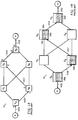
- node A of network 10 performs a set up procedure to open a virtual circuit route that encompasses the switches S A-D .
- This route is identified by a virtual circuit (VC) number, VC2, that is associated with node A's local switch S A .
- VC2 virtual circuit
- each switch along VC2 maintains a forwarding table with entries indicating where to forward the data packets in accordance with the routing configuration results.
- Fig. 1B illustrates the forwarding tables 20a-d contained within the switches S A-D of the network 10.
- Each entry of the tables includes an incoming portion and an outgoing portion, with each portion including a port name and a VC number associated with that port.
- Each data packet transferred over the network contains a VC field identifying the open VC number on which it has arrived.
- that switch searches the left (incoming) portion 22i of its table 20c, using the incoming port, e.g., Z, and VC number found in the packet, e.g., VC7, as the key.
- the outgoing portion 22o of the entry identifies the VC number, e.g., VC4, to insert into the VC field of the packet and the port, e.g., Q, to which it should pass the packet. It is therefore apparent that the VC numbers and forwarding tables provide enough information to guide the data packets through the allocated switches and links to the destination.
- the VC number e.g., VC4
- the port e.g., Q
- Multicasting involves transmitting a single multicast packet from a source node and having it received by a group of destination nodes.
- a problem associated with this type of point-to-multipoint communication technique concerns forming an efficient "delivery tree", i.e., a collection of nodes and links, that the multicast packet must traverse to reach the destination nodes.
- One approach known as Core Based Trees (CBT)
- CBT Core Based Trees
- addresses this problem by establishing a core, point-to-point virtual circuit "tree” and then executing a set up procedure for each additional destination node of the group.
- CBT approach is “static”, in the sense that if a more efficient path exists, the delivery tree cannot easily be adapted to the "better" topology.
- Another problem involves adding and deleting nodes from the multicast group of destinations.
- each destination node initiates a procedure to add or delete itself; accordingly, the source node is unaware of the tree configuration and its constituent destination nodes.
- a tree is formed that consists of virtual circuits from source node N to a multicast group of destination nodes D1 and D2; specifically, the virtual circuit to node D1 encompasses switches S A and S F , and the virtual circuit to node D2 encompasses switches S A-D .
- a branch link represented by VC8 is subsequently formed with the tree to add node D3 to the group of destination nodes.
- VC8 forms a "loop" among the switches S A , S B , S C and S F and the intervening links, thereby creating an unstable topology.
- the tree connections are bidirectional, i.e, packets may flow through the ports of switches S A and S C in both directions as indicated by the double-headed arrows 22, a packet that is propagating within the loop may revolve endlessly around that loop, thereby adversely affecting the bandwidth of the network.
- the connections are unidirectional as indicated by the single-headed arrows 21 flowing into switch S E , duplicate copies of the packets may be delivered to the destination node D3 which, again, negatively affect bandwidth.
- Another known point-to-multipoint communication technique requires each destination node to "register" with its local switch to receive packets addressed to a particular multicast address. Specifically, the destination node sends a request to its local switch, which then forwards the request to all the switches in the network. Each switch in the network updates its forwarding table to store routing information, i.e., state, pertaining to all of the destination nodes for each multicast address.
- routing information i.e., state
- Point-to-multipoint communication in a connectionless network involves transmitting a single multicast packet that is received by multiple destinations.
- each multicast packet contains a list of destination nodes.
- that switch checks the list to select a set of outgoing links that will provide the best route to at least one of the destinations.
- the switch generates a new copy of the multicast packet for each selected outgoing link and includes, in each packet, those destinations that use the link.
- each multicast packet will identify only one destination and is treated as a normal data packet.
- the present invention provides a method and apparatus for creating multicast virtual circuits in an arbitrary-topology network without disrupting the operation of the network.
- Also explained hereinafter is a mechanism for establishing multicast virtual circuits incorporating features of a connection-oriented and a connectionless network.
- the present invention resides in a novel multicast connection arrangement by which a source node may establish virtual circuits to a group of destination nodes by executing a single procedure, and may subsequently modify those circuits, i.e., add or delete destination nodes, with a related procedure.
- the switches and links allocated to the multiple-destination virtual circuits of an arbitrary-topology network are elements of multicast virtual circuits .
- only switches of the multicast virtual circuits need maintain routing information relating to the destination nodes.
- the invention enables the source node to maintain control of the virtual circuit configurations, while optimizing the bandwidth, throughput and efficiency of the arbitrary-topology network.
- the invention in its broad form resides in a method for establishing a multicast virtual circuit as recited in claim 1.
- the invention also resides in an arrangement for establishing multicast virtual circuits as recited in claim 9.
- a multicast setup packet is used to open multicast virtual circuits.
- the multicast setup packet contains a multicast identifier field, a virtual circuit field and a destination field identifying a list of desired destination node addresses.
- a source node Prior to issuing the multicast setup packet, a source node enters appropriate information into each of the fields, with the VC field containing a virtual circuit value associated with the port connecting the source to its local switch.
- the local switch Upon receiving the packet at its incoming port, the local switch checks the list of destination nodes and selects a set of outgoing links that provide the best route to at least one of the destination nodes. Selection is based upon the results of route configuration, e.g., availability and loading, analysis. This group of incoming and outgoing ports is called a multicast port group .
- the switch then generates entries of an internal forwarding table for the newly-formed multicast group.
- the entries contain routing information, i.e., state, such as (i) a unique multicast identifier (MI) value that is acquired from the identifier field, (ii) the name of the incoming port and its associated VC value acquired from the VC field and (iii) the names of the selected outgoing ports and their associated VC values.
- MI multicast identifier
- the switch marks the incoming VC value entry as originating from the source node.
- the switch Prior to forwarding each packet onto its respective outgoing link, the switch generates a copy of the multicast setup packet for each of the selected outgoing ports. The switch then updates both the VC field to contain a VC value associated with each selected outgoing port and the destination field to contain only those destination nodes receiving the copy of the packet. Finally, the packets are transferred over the network.
- each multicast setup packet After traversing a number of successive switches, each multicast setup packet identifies only one destination, thereby effectively "opening" a virtual circuit. Data packets subsequently issued by the source need only include the initial local VC value in order propagate along the multicast virtual circuits and arrive at the respective destination nodes.
- the multicast setup packet is also used to add destination nodes to the multicast virtual circuits.
- the fields of the packet contain the same information used when opening the virtual circuits, except that the destination field now contains only the new destination node addresses.
- each switch of the multicast virtual circuits Upon receiving the "additional" multicast setup packet, each switch of the multicast virtual circuits again performs a configuration analysis to determine the best routes.
- each switch also executes a topology analysis process to detect whether the added nodes will create loops in the network or will result in the creation of duplicate packets.
- the first step of the process involves each switch checking the entries of its forwarding table to determine if the incoming port, through which the multicast setup packet is entering the switch, is allocated to an open multicast virtual circuit having an MI value that matches the MI value of the packet. If not, the next step involves an inquiry of whether there are any existing entries in the table associated with that particular MI value.
- the switch maintains a separate virtual circuit for each of the existing and added destinations, or (ii) the switch deletes the port marked as being from the source and establishes a "new" virtual circuit connection using the added incoming port. The switch then updates the entries of the forwarding table to reflect the changed topology.
- a multicast delete packet is used to delete an existing node (and link) from the list of destinations associated with the multicast virtual circuits.
- the multicast delete packet is issued by the destination node seeking removal from the virtual circuit.
- the packet need only contain the unique multicast identifier value and the VC value of the port to be deleted.
- a source node can initiate virtual circuit connections to destination nodes with a single setup procedure, thereby allowing the source to efficiently control the configuration of nodes and implement management, i.e., auditing, functions.
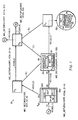
- Fig. 3 depicts a connection-oriented, arbitrary-topology network 30 of interconnected nodes in which the multicast connection arrangement of this invention may be advantageously used.
- the nodes are typically general-purpose computers comprising a source node N and a group of destination nodes G1-3. Each node is coupled to a respective "local" switch S, i.e., a specialized computer. Each switch S is configured to facilitate the flow of information in the network 30 by providing, along with its incoming and outgoing links L, connections between the source and destination nodes.
- Each node and switch typically comprises a central processing unit (CPU) 35, a memory unit 34 and at least one network adapter 32 interconnected by a system bus 36.
- the main memory 34 may comprise storage locations typically composed of random access memory (RAM) devices, which are addressable by the CPU and network adapter.
- RAM random access memory
- An operating system portions of which are typically resident in main memory 34 and executed by CPU 35, functionally organizes the nodes and switches. The operating system invokes network operations in support of programs executing in the CPU 25.
- a point-to-point virtual circuit is established between a source node and a destination node prior to "adding" nodes to the circuit.
- a multicast connection procedure provides a means for efficiently "opening" multicast virtual circuit routes using a single procedure. Specifically, the procedure allocates appropriate switches and their connecting links to establish the best routes between the source node and destination nodes prior to transferring information from the source to those destinations. Selection is effected by conventional adaptive-type routing algorithms used in route configuration analysis. The information is encapsulated as a packet and the packet is forwarded from the source node's local switch to each of the destination nodes' local switches via one or more intermediate switches.
- the packet when the packet is received at an incoming port of an intermediate switch, it is stored there until the routing determination is made as to which of the outgoing ports the packet will be forwarded.
- This group of ports is called a multicast port group.
- a feature of the invention is that only those switches of the multicast virtual circuits need maintain routing information relating to the destination nodes.
- the invention enables the source node to maintain control of the virtual circuit configurations, while optimizing the bandwidth, throughput and efficiency of the arbitrary-topology network.
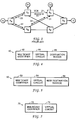
- the source node N creates a multicast setup packet, MC_SETUP, the format of which is shown in Fig. 4.
- the MC_SETUP packet 40 contains a multicast identifier (MI) field 42, a virtual circuit (VC) field 44 and a destination nodes field 46, the latter field identifying a list of desired destination node addresses, e.g., G1-3.
- MI multicast identifier
- VC virtual circuit
- destination nodes field 46 the latter field identifying a list of desired destination node addresses, e.g., G1-3.
- An example of the contents of the MI field may be a user identification number, e.g., UID, concatenated to an instantaneous value of a real-time clock, e.g., RT, to provide a unique multicast identifier, e.g., UIDRT.
- the source node N enters the appropriate information into each of the fields, with the VC field 44 containing a virtual circuit value, e.g., VC30, associated with the port X1 connecting the source N to its local switch S N .
- a virtual circuit value e.g., VC30
- the resulting completed multicast setup packet generated by source N may be represented as MC_SETUP (UIDRT, VC30, G1-3).
- the source N forwards the packet 40 to its local switch S N , which checks the list of nodes G1-3 in the D field 46 and selects a set of outgoing ports, each of which provides the best route to at least one of these destination nodes.
- the ports X2 and X6 are selected, with X2 providing the best virtual circuit route, VC7, to nodes G1 and G2, and X6 providing the best route VC17 to G3.
- the MC_SETUP packet is "spawned" at the switch S N and a copy of the packet is generated for each port X2 and X6 of the multicast group.
- the switch S N also generates entries in its internal forwarding table 300 for the MC_SETUP packet 40, with each entry 320 containing routing state such as the UIDRT value acquired from the MI field 42, the incoming port X1 and its associated VC30 value acquired from the VC field 44 and outgoing VC7 and VC17 values selected for the outgoing ports X2 and X6, respectively.
- the switch marks the incoming VC30 value with the letter "N", indicating that this entry originated from the source node.
- the switch S N Prior to forwarding each packet to its respective port, the switch S N updates the VC field 44 of each packet 40 to contain the VC value associated with each selected outgoing port and modifies the destination field 46 to contain only those destinations using that particular port. Accordingly, MC_SETUP (UIDRT, VC7, G1-2) is forwarded through port X2 and onto link L2, while MC_SETUP (UIDRT, VC17, G3) is forwarded through port X6 and onto link L6.
- MC_SETUP (UIDRT, VC9, G1,2) is forwarded onto link L3 by switch S2 and is thereafter spawned into two multicast setup packets at switch S3.
- MC_SETUP (UIDRT, VC14, G1) is passed to node G1
- MC_SETUP (UIDRT, VC22, G2) is passed to node G2.
- the multicast virtual circuts are effectively "opened". Since each switch along the multicast virtual circuits maintains routing state relating to the best routes to the destination nodes, data packets subsequently issued by the source node N need only contain the initial local VC value in order propagate along each virtual circuit and arrive at the respective destination nodes. Furthermore, if a packet issued by destination node G1 or G2 arrives at port X2 of switch S N having a VC value VC7, the switch S N forwards the packet out the remaining ports of the multicast group, e.g., out port X1 with a VC value VC30 and out port X6 with a VC value VC17.
- a multicast setup packet may also be used by a source node to add destination nodes to previously-opened multicast virtual circuits.
- Fig. 5 illustrates the format of a this type of packet 50.
- the multicast identifier (MI) field 52 and virtual circuit (VC) field 54 of the packet 50 contain the same information that is contained in the MI field 42 and VC field 44 of the packet 40 (Fig. 4); however, the new destination node(s) field 56 now contains only the new destination node address(es).
- each switch S of the multicast virtual circuits (Fig. 3) performs a configuration analysis to determine the best route(s) to new destination node(s) and stores the results of the analysis in its forwarding table.
- the multicast connection arrangement also provides a means for preventing the creation of an unstable network topology when adding destination nodes to the multicast virtual circuits.
- each switch S of the multicast virtual circuits executes a two-step topology analysis process to detect whether the added node(s) will create loop(s) in the network or will result in the creation of duplicate packets.
- the first step of the process involves each switch S checking the entries of its forwarding table to determine if the incoming port, through which the multicast setup packet 50 is entering the switch, is allocated to a multicast virtual circuit having an MI value that matches the MI value of the packet 50. If not, the next step involves an inquiry of whether there are any existing entries in the table associated with that particular MI value.
- the switch may maintain a separate virtual circuit for each of the existing and added destination nodes, or it may delete the port marked as being from the source and establish a "new" virtual circuit connection using the added incoming port. Either alternative obviates the formation of a loop (Fig. 2) and is thus contemplated within the teachings of the invention.
- the switch then updates the entries of its forwarding table to reflect the changed topology.
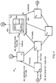
- FIG. 6 depicts a connection-oriented, arbitrary-topology network 60 in which the multicast setup packet may be advantageously used to add a destination node to the network.
- the open multicast virtual circuits between the source node N and destination nodes G1-2 are shown as darken fines.
- the source node N creates a multicast setup packet 50 to add destination node G3 (see dotted line) and the resulting completed packet 50 MC_SETUP (UIDRT, VC30, G3), is forwarded to the switch S N , where the results of a routing analysis indicates that the packet should be passed on to switch S1. Therefore, switch S N modifies the contents of the VC field to reflect the multicast virtual circuit VC7 and passes the packet to switch S1. There, the results of another routing analysis indicate that the packet should be forwarded to node G3 via switch S2.
- Switch S2 then checks the entries of its forwarding table 600 to determine if the incoming port X3, through which the multicast setup packet 50 is entering the switch, is allocated to a multicast virtual circuit having an MI value that matches the MI value, e.g., UIDRT, of the packet 50. An examination of the forwarding table reveals no match. Therefore, the switch S2 determines whether there are any existing entries in the table associated with the MI value UIDRT. In this example, there is an existing entry having the MI value UIDRT, indicating that packet may be looping.
- MI value e.g., UIDRT
- the switch S2 thus either maintains a separate virtual circuit for each of the existing and added destination nodes (separate dotted lines in switch S2 at 65a,b), or it deletes, in its forwarding table, the port marked as being from the source N (see forwarding table entry X:15 " delete " at 66). Further to this latter option, the switch establishes a new virtual circuit connection comprising the latter incoming port X3 and virtual circuit VC9 (see forwarding table 600 at 68). In either case, the switch S2 updates the entries of its forwarding table 600 to reflect the changed circuit topology.
- a multicast delete packet is used to delete an existing node (and port) from the list of destinations associated with the multicast virtual circuits.
- Fig. 7 illustrates the format of a multicast delete packet 70 which need only contain a unique MI value in a multicast identifier field 72 and a VC value, pertaining to a port to be deleted, in a virtual circuit field 74.
- the multicast delete packet is formed by the destination node seeking removal from the virtual circuit and is forwarded to the remaining elements of the multicast virtual circuit.
- the switch selection, by the switches, of the "best" virtual circuit routes is based upon topology and traffic conditions existing when the set up procedure or related modification procedures described herein are performed. For example, it is possible that a particular route was chosen as the best route because a certain link was non-operational or congested. Therefore, to ensure that the selected multicast virtual circuit routes are optimized, the set up (and modification) procedure is preferably executed at periodic intervals.
Abstract
Description
- This invention relates generally to network systems and, more specifically, to multicast virtual circuits in arbitrary-topology networks.
- A computer network typically comprises a collection of interconnected nodes, such as computer systems and switches, which may, in turn, be connected through an irregular configuration of transmission lines, i.e., links. The switches are specialized computers used to connect two or more links. Data is exchanged among nodes of such an "arbitrary-topology" network by passing packets from switch to switch over the links. Specifically, when a packet arrives on an incoming link, the switch decides onto which of the outgoing links that packet will be forwarded.
- In a connection-oriented network, a virtual circuit is commonly established when exchanging packets between nodes of the network. The virtual circuit is a temporary logical path connection that requires a set up procedure to "open" the virtual circuit prior to transferring the data packets and a release procedure to "close" the circuit once the data transfer is complete. This obviates the need for effecting routing decisions for each data packet that is transferred between the nodes once the circuit is opened.
- For point-to-point communication, the set up procedure creates a virtual circuit by allocating certain switches and links in the network to establish the "best" route, according to conventional route configuration techniques, between a source node and a destination node. To illustrate, refer to Fig. 1A. Here, node A of
network 10 performs a set up procedure to open a virtual circuit route that encompasses the switches SA-D. This route is identified by a virtual circuit (VC) number, VC2, that is associated with node A's local switch SA. In order to ensure that data packets subsequently transferred from node A always follow this virtual circuit route to node D, each switch along VC2 maintains a forwarding table with entries indicating where to forward the data packets in accordance with the routing configuration results. - Fig. 1B illustrates the forwarding tables 20a-d contained within the switches SA-D of the
network 10. Each entry of the tables includes an incoming portion and an outgoing portion, with each portion including a port name and a VC number associated with that port. Each data packet transferred over the network contains a VC field identifying the open VC number on which it has arrived. Thus, when a packet is received at an incoming port of switch SC, that switch searches the left (incoming)portion 22i of its table 20c, using the incoming port, e.g., Z, and VC number found in the packet, e.g., VC7, as the key. When a match is found, the outgoing portion 22o of the entry identifies the VC number, e.g., VC4, to insert into the VC field of the packet and the port, e.g., Q, to which it should pass the packet. It is therefore apparent that the VC numbers and forwarding tables provide enough information to guide the data packets through the allocated switches and links to the destination. - Multicasting involves transmitting a single multicast packet from a source node and having it received by a group of destination nodes. A problem associated with this type of point-to-multipoint communication technique concerns forming an efficient "delivery tree", i.e., a collection of nodes and links, that the multicast packet must traverse to reach the destination nodes. One approach, known as Core Based Trees (CBT), addresses this problem by establishing a core, point-to-point virtual circuit "tree" and then executing a set up procedure for each additional destination node of the group. However, the CBT approach is "static", in the sense that if a more efficient path exists, the delivery tree cannot easily be adapted to the "better" topology.
- Another problem involves adding and deleting nodes from the multicast group of destinations. In CBT networks, each destination node initiates a procedure to add or delete itself; accordingly, the source node is unaware of the tree configuration and its constituent destination nodes.
- An alternative to the CBT technique involves creating subsequent "branch" links for the additional destination nodes without destroying the existing tree connections. Such an approach is illustrated in Fig. 2. Here, a tree is formed that consists of virtual circuits from source node N to a multicast group of destination nodes D1 and D2; specifically, the virtual circuit to node D1 encompasses switches SA and SF, and the virtual circuit to node D2 encompasses switches SA-D.
- A branch link represented by VC8 is subsequently formed with the tree to add node D3 to the group of destination nodes. However, the addition of VC8, in turn, forms a "loop" among the switches SA, SB, SC and SF and the intervening links, thereby creating an unstable topology. Specifically, if the tree connections are bidirectional, i.e, packets may flow through the ports of switches SA and SC in both directions as indicated by the double-
headed arrows 22, a packet that is propagating within the loop may revolve endlessly around that loop, thereby adversely affecting the bandwidth of the network. If the connections are unidirectional as indicated by the single-headed arrows 21 flowing into switch SE, duplicate copies of the packets may be delivered to the destination node D3 which, again, negatively affect bandwidth. - Another known point-to-multipoint communication technique requires each destination node to "register" with its local switch to receive packets addressed to a particular multicast address. Specifically, the destination node sends a request to its local switch, which then forwards the request to all the switches in the network. Each switch in the network updates its forwarding table to store routing information, i.e., state, pertaining to all of the destination nodes for each multicast address. A disadvantage of this technique is that a significant amount of processing and storage overhead is needed for each switch to maintain state for each destination node.
- Point-to-multipoint communication in a connectionless network involves transmitting a single multicast packet that is received by multiple destinations. For this type of network, however, each multicast packet contains a list of destination nodes. When the packet arrives at an incoming link of a first switch, that switch checks the list to select a set of outgoing links that will provide the best route to at least one of the destinations. The switch generates a new copy of the multicast packet for each selected outgoing link and includes, in each packet, those destinations that use the link. Ultimately, each multicast packet will identify only one destination and is treated as a normal data packet.
- The present invention provides a method and apparatus for creating multicast virtual circuits in an arbitrary-topology network without disrupting the operation of the network.
- Also taught herein are a method and apparatus for adding nodes to established multicast virtual circuits without affecting the performance of the network, a method and apparatus for easily modifying established multicast virtual circuits to reflect a more efficient topology.
- Also explained hereinafter is a mechanism for establishing multicast virtual circuits incorporating features of a connection-oriented and a connectionless network.
- The present invention resides in a novel multicast connection arrangement by which a source node may establish virtual circuits to a group of destination nodes by executing a single procedure, and may subsequently modify those circuits, i.e., add or delete destination nodes, with a related procedure. The switches and links allocated to the multiple-destination virtual circuits of an arbitrary-topology network are elements of multicast virtual circuits. In accordance with the arrangement, only switches of the multicast virtual circuits need maintain routing information relating to the destination nodes. Thus, the invention enables the source node to maintain control of the virtual circuit configurations, while optimizing the bandwidth, throughput and efficiency of the arbitrary-topology network.
- The invention in its broad form resides in a method for establishing a multicast virtual circuit as recited in claim 1. The invention also resides in an arrangement for establishing multicast virtual circuits as recited in
claim 9. - In one aspect of the invention, a multicast setup packet is used to open multicast virtual circuits. The multicast setup packet contains a multicast identifier field, a virtual circuit field and a destination field identifying a list of desired destination node addresses. Prior to issuing the multicast setup packet, a source node enters appropriate information into each of the fields, with the VC field containing a virtual circuit value associated with the port connecting the source to its local switch.
- Upon receiving the packet at its incoming port, the local switch checks the list of destination nodes and selects a set of outgoing links that provide the best route to at least one of the destination nodes. Selection is based upon the results of route configuration, e.g., availability and loading, analysis. This group of incoming and outgoing ports is called a multicast port group.
- The switch then generates entries of an internal forwarding table for the newly-formed multicast group. The entries contain routing information, i.e., state, such as (i) a unique multicast identifier (MI) value that is acquired from the identifier field, (ii) the name of the incoming port and its associated VC value acquired from the VC field and (iii) the names of the selected outgoing ports and their associated VC values. In addition, the switch marks the incoming VC value entry as originating from the source node.
- Prior to forwarding each packet onto its respective outgoing link, the switch generates a copy of the multicast setup packet for each of the selected outgoing ports. The switch then updates both the VC field to contain a VC value associated with each selected outgoing port and the destination field to contain only those destination nodes receiving the copy of the packet. Finally, the packets are transferred over the network.
- After traversing a number of successive switches, each multicast setup packet identifies only one destination, thereby effectively "opening" a virtual circuit. Data packets subsequently issued by the source need only include the initial local VC value in order propagate along the multicast virtual circuits and arrive at the respective destination nodes.
- The multicast setup packet is also used to add destination nodes to the multicast virtual circuits. The fields of the packet contain the same information used when opening the virtual circuits, except that the destination field now contains only the new destination node addresses. Upon receiving the "additional" multicast setup packet, each switch of the multicast virtual circuits again performs a configuration analysis to determine the best routes.
- As described herein, each switch also executes a topology analysis process to detect whether the added nodes will create loops in the network or will result in the creation of duplicate packets. The first step of the process involves each switch checking the entries of its forwarding table to determine if the incoming port, through which the multicast setup packet is entering the switch, is allocated to an open multicast virtual circuit having an MI value that matches the MI value of the packet. If not, the next step involves an inquiry of whether there are any existing entries in the table associated with that particular MI value. If the answer to the latter question is yes, two options are available: (i) the switch maintains a separate virtual circuit for each of the existing and added destinations, or (ii) the switch deletes the port marked as being from the source and establishes a "new" virtual circuit connection using the added incoming port. The switch then updates the entries of the forwarding table to reflect the changed topology.
- In a modification, a multicast delete packet is used to delete an existing node (and link) from the list of destinations associated with the multicast virtual circuits. Here, the multicast delete packet is issued by the destination node seeking removal from the virtual circuit. Specifically, the packet need only contain the unique multicast identifier value and the VC value of the port to be deleted.
- Advantageously, as described herein, a source node can initiate virtual circuit connections to destination nodes with a single setup procedure, thereby allowing the source to efficiently control the configuration of nodes and implement management, i.e., auditing, functions.
- By using the method and arrangement taught herein, changes to multicast virtual circuits can be performed quicky and efficiently without degrading the network because of loop creation and duplicate packet generation.
- A more detailed understanding of the invention may be had from the following description of a preferred embodiment, given by way of example and to be understood in conjunction with the accompanying drawing wherein:
- Fig. 1A is a diagram of a conventionally-established, virtual circuit connecting a source node and a destination node of a network;
- Fig. 1B is a block diagram of conventional forwarding tables and the information contained therein relating to the virtual circuit of Fig. 1A;
- Fig. 1 is a diagram of a conventional delivery tree circuit with branch links for adding nodes to a group of destination nodes;
- Fig. 2 is a diagram of a connection-oriented, arbitrary-topology network in which the multicast connection arrangement of this invention may be advantageously used;
- Fig. 3 illustrates the format of a multicast setup packet used to open multicast virtual circuits in accordance with the invention;
- Fig. 4 illustrates the format of a multicast setup packet used to add nodes to open multicast virtual circuits in accordance with a preferred embodiment of the invention;
- Fig. 5 illustrates the format of a multicast setup packet used to add nodes to open multicast virtual circuits in accordance with a preferred embodiment of the invention;
- Fig. 6 is a diagram of a connection-oriented, arbitrary-topology network in which the multicast setup packet of Fig. 5 may be advantageously used to add a destination node to the network; and
- Fig. 7 illustrates the format of a multicast delete packet used to delete nodes from open multicast virtual circuits in accordance with a preferred embodiment of the invention.
- Fig. 3 depicts a connection-oriented, arbitrary-
topology network 30 of interconnected
nodes in which the multicast connection arrangement of this invention may be advantageously used. The nodes are typically general-purpose computers comprising a source node N and a group of destination nodes G1-3. Each node is coupled to a respective "local" switch S, i.e., a specialized computer. Each switch S is configured to facilitate the flow of information in thenetwork 30 by providing, along with its incoming and outgoing links L, connections between the source and destination nodes. - Each node and switch typically comprises a central processing unit (CPU) 35, a
memory unit 34 and at least onenetwork adapter 32 interconnected by asystem bus 36. Themain memory 34 may comprise storage locations typically composed of random access memory (RAM) devices, which are addressable by the CPU and network adapter. An operating system, portions of which are typically resident inmain memory 34 and executed byCPU 35, functionally organizes the nodes and switches. The operating system invokes network operations in support of programs executing in the CPU 25. - As previously noted, in conventional, connection-oriented networks, a point-to-point virtual circuit is established between a source node and a destination node prior to "adding" nodes to the circuit. In accordance with the invention, a multicast connection procedure provides a means for efficiently "opening" multicast virtual circuit routes using a single procedure. Specifically, the procedure allocates appropriate switches and their connecting links to establish the best routes between the source node and destination nodes prior to transferring information from the source to those destinations. Selection is effected by conventional adaptive-type routing algorithms used in route configuration analysis. The information is encapsulated as a packet and the packet is forwarded from the source node's local switch to each of the destination nodes' local switches via one or more intermediate switches.
- In general, when the packet is received at an incoming port of an intermediate switch, it is stored there until the routing determination is made as to which of the outgoing ports the packet will be forwarded. This group of ports is called a multicast port group. A feature of the invention is that only those switches of the multicast virtual circuits need maintain routing information relating to the destination nodes. Thus, the invention enables the source node to maintain control of the virtual circuit configurations, while optimizing the bandwidth, throughput and efficiency of the arbitrary-topology network.
- In order to open the multicast virtual circuits, the source node N creates a multicast setup packet, MC_SETUP, the format of which is shown in Fig. 4. The
MC_SETUP packet 40 contains a multicast identifier (MI)field 42, a virtual circuit (VC)field 44 and adestination nodes field 46, the latter field identifying a list of desired destination node addresses, e.g., G1-3. An example of the contents of the MI field may be a user identification number, e.g., UID, concatenated to an instantaneous value of a real-time clock, e.g., RT, to provide a unique multicast identifier, e.g., UIDRT. The source node N enters the appropriate information into each of the fields, with theVC field 44 containing a virtual circuit value, e.g., VC30, associated with the port X1 connecting the source N to its local switch SN. Accordingly, for the example illustrated herein, the resulting completed multicast setup packet generated by source N may be represented as MC_SETUP (UIDRT, VC30, G1-3). - Refer again to Fig. 3. The source N forwards the
packet 40 to its local switch SN, which checks the list of nodes G1-3 in theD field 46 and selects a set of outgoing ports, each of which provides the best route to at least one of these destination nodes. Here, the ports X2 and X6 are selected, with X2 providing the best virtual circuit route, VC7, to nodes G1 and G2, and X6 providing the best route VC17 to G3. Because there are two distinct routes to the destination nodes, the MC_SETUP packet is "spawned" at the switch SN and a copy of the packet is generated for each port X2 and X6 of the multicast group. - The switch SN also generates entries in its internal forwarding table 300 for the
MC_SETUP packet 40, with eachentry 320 containing routing state such as the UIDRT value acquired from theMI field 42, the incoming port X1 and its associated VC30 value acquired from theVC field 44 and outgoing VC7 and VC17 values selected for the outgoing ports X2 and X6, respectively. In addition, the switch marks the incoming VC30 value with the letter "N", indicating that this entry originated from the source node. - Prior to forwarding each packet to its respective port, the switch SN updates the
VC field 44 of eachpacket 40 to contain the VC value associated with each selected outgoing port and modifies thedestination field 46 to contain only those destinations using that particular port. Accordingly, MC_SETUP (UIDRT, VC7, G1-2) is forwarded through port X2 and onto link L2, while MC_SETUP (UIDRT, VC17, G3) is forwarded through port X6 and onto link L6. - The procedure described above is repeated at each intermediate switch along the multicast virtual circuits until each
MC_SETUP packet 40 identifies only one destination. Thus, as an example, MC_SETUP (UIDRT, VC9, G1,2) is forwarded onto link L3 by switch S₂ and is thereafter spawned into two multicast setup packets at switch S₃. One of the resulting packets, MC_SETUP (UIDRT, VC14, G1) is passed to node G1, while the other packet, MC_SETUP (UIDRT, VC22, G2) is passed to node G2. - At this point, the multicast virtual circuts are effectively "opened". Since each switch along the multicast virtual circuits maintains routing state relating to the best routes to the destination nodes, data packets subsequently issued by the source node N need only contain the initial local VC value in order propagate along each virtual circuit and arrive at the respective destination nodes. Furthermore, if a packet issued by destination node G1 or G2 arrives at port X2 of switch SN having a VC value VC7, the switch SN forwards the packet out the remaining ports of the multicast group, e.g., out port X1 with a VC value VC30 and out port X6 with a VC value VC17.
- A multicast setup packet may also be used by a source node to add destination nodes to previously-opened multicast virtual circuits. Fig. 5 illustrates the format of a this type of packet 50. For this application, the multicast identifier (MI)
field 52 and virtual circuit (VC)field 54 of the packet 50 contain the same information that is contained in theMI field 42 andVC field 44 of the packet 40 (Fig. 4); however, the new destination node(s)field 56 now contains only the new destination node address(es). Upon receiving the "additional" multicast setup packet 50, each switch S of the multicast virtual circuits (Fig. 3) performs a configuration analysis to determine the best route(s) to new destination node(s) and stores the results of the analysis in its forwarding table. - The multicast connection arrangement also provides a means for preventing the creation of an unstable network topology when adding destination nodes to the multicast virtual circuits. Specifically, each switch S of the multicast virtual circuits executes a two-step topology analysis process to detect whether the added node(s) will create loop(s) in the network or will result in the creation of duplicate packets. In accordance with the invention, the first step of the process involves each switch S checking the entries of its forwarding table to determine if the incoming port, through which the multicast setup packet 50 is entering the switch, is allocated to a multicast virtual circuit having an MI value that matches the MI value of the packet 50. If not, the next step involves an inquiry of whether there are any existing entries in the table associated with that particular MI value.
- If the response to latter inquiry is affirmative, the switch may maintain a separate virtual circuit for each of the existing and added destination nodes, or it may delete the port marked as being from the source and establish a "new" virtual circuit connection using the added incoming port. Either alternative obviates the formation of a loop (Fig. 2) and is thus contemplated within the teachings of the invention. The switch then updates the entries of its forwarding table to reflect the changed topology.
- An example of the topology analysis process is provided in connection with Fig. 6, which depicts a connection-oriented, arbitrary-
topology network 60 in which the multicast setup packet may be advantageously used to add a destination node to the network. The open multicast virtual circuits between the source node N and destination nodes G1-2 are shown as darken fines. The source node N creates a multicast setup packet 50 to add destination node G3 (see dotted line) and the resulting completed packet 50 MC_SETUP (UIDRT, VC30, G3), is forwarded to the switch SN, where the results of a routing analysis indicates that the packet should be passed on to switch S₁. Therefore, switch SN modifies the contents of the VC field to reflect the multicast virtual circuit VC7 and passes the packet to switch S₁. There, the results of another routing analysis indicate that the packet should be forwarded to node G3 via switch S₂. - Switch S₂ then checks the entries of its forwarding table 600 to determine if the incoming port X3, through which the multicast setup packet 50 is entering the switch, is allocated to a multicast virtual circuit having an MI value that matches the MI value, e.g., UIDRT, of the packet 50. An examination of the forwarding table reveals no match. Therefore, the switch S₂ determines whether there are any existing entries in the table associated with the MI value UIDRT. In this example, there is an existing entry having the MI value UIDRT, indicating that packet may be looping. The switch S₂ thus either maintains a separate virtual circuit for each of the existing and added destination nodes (separate dotted lines in switch S₂ at 65a,b), or it deletes, in its forwarding table, the port marked as being from the source N (see forwarding table entry X:15 "delete" at 66). Further to this latter option, the switch establishes a new virtual circuit connection comprising the latter incoming port X3 and virtual circuit VC9 (see forwarding table 600 at 68). In either case, the switch S₂ updates the entries of its forwarding table 600 to reflect the changed circuit topology.
- In another aspect of the invention, a multicast delete packet is used to delete an existing node (and port) from the list of destinations associated with the multicast virtual circuits. Fig. 7 illustrates the format of a multicast delete
packet 70 which need only contain a unique MI value in amulticast identifier field 72 and a VC value, pertaining to a port to be deleted, in avirtual circuit field 74. The multicast delete packet is formed by the destination node seeking removal from the virtual circuit and is forwarded to the remaining elements of the multicast virtual circuit. - It should be noted that selection, by the switches, of the "best" virtual circuit routes is based upon topology and traffic conditions existing when the set up procedure or related modification procedures described herein are performed. For example, it is possible that a particular route was chosen as the best route because a certain link was non-operational or congested. Therefore, to ensure that the selected multicast virtual circuit routes are optimized, the set up (and modification) procedure is preferably executed at periodic intervals.
- The foregoing description has been limited to a specific embodiment of this invention. It will be apparent, however, that variations and modifications may be made to the invention, with the attainment of some or all of its advantages.
Claims (9)
- In an arbitrary-topology network having nodes, switches and interconnecting links, a method for establishing a multicast virtual circuit between a source node and a group of destination nodes, said method comprising the steps of:
creating a multicast setup packet at the source node for transfer to the group destination nodes, said multicast setup packet containing a multicast identifer field for storing a unique multicast identifier value, a virtual circuit field and a destination field identifying the group of destination nodes receiving said multicast setup packet; and
allocating selected switches and interconnecting links of said network as elements of said multicast virtual circuits for receiving said multicast setup packet, each of said elements providing a best route for said multicast setup packet to at least one of the group of destination nodes. - The method of Claim 1 wherein said step of allocating comprises the steps of:
forwarding said multicast setup packet to a first allocated switch of said multicast virtual circuits, said first allocated switch being associated with the source node and said packet being received at an incoming port of said first allocated switch;
selecting at least one outgoing port of said first allocated switch for transfer of said multicast packet, each of the selected outgoing ports providing a best route to at least one of the group of destination nodes;
generating at least one copy of said multicast packet for each of the selected outgoing ports; and
transferring each copy of said multicast packet through each of the selected outgoing ports to one of a subsequent allocated switch and the at least one of the group of destination nodes. - The method of Claim 2 wherein said step of allocating further comprises the step of:
generating entries of a forwarding table located within said first allocated switch, said entries containing routing information pertaining to the incoming port associated with the source node and the selected outgoing ports associated with the group of destination nodes contained within said destination field of said multicast setup packet,
whereby only said selected switches of said multicast virtual circuits need maintain routing information relating to the destination nodes in said forwarding table. - The method of Claim 3 wherein said step of generating at least one copy of said multicast packet further comprises the steps of:
updating said virtual circuit field of each copy of said multicast setup packet to contain a virtual circuit value associated with each selected outgoing port; and
updating said destination field of each copy of said multicast setup packet to contain only those destination nodes receiving the copy of said packet. - The method of Claim 4 wherein said step of generating entries further comprises the step of marking said virtual circuit value as originating from the source node.
- The method of Claim 5 wherein said step of selecting comprises the steps of:
determining if the incoming port is allocated to an open multicast virtual circuit having a multicast identifier value that matches said unique multicast identifier value stored in said multicast setup packet. - The method of Claim 6 wherein said step of selecting further comprises the steps of, if the incoming port is not allocated to an open multicast virtual circuit having a matching unique multicast identifier value:
determining if there are any existing entries in said forwarding table associated with said unique multicast identifier. - The method of Claim 7 wherein said step of selecting further comprises the steps of, if there are existing entries in said forwarding table associated with said unique multicast identifier:
deleting said port marked as being from the source node and establishing a multicast virtual circuit with the added incoming port. - In an arbitrary-topology network having nodes, switches and interconnecting links, an arrangement for establishing multicast virtual circuits between a source node and a group of destination nodes, said arrangement comprising:
means for creating a multicast setup packet for transfer to the group destination nodes, said multicast setup packet containing a multicast identifer field, a virtual circuit field and a destination field identifying the group of destination nodes receiving said multicast setup packet; and
means for allocating selected switches and interconnecting links of said network as elements of said multicast virtual circuits for receiving said multicast setup packet, each of said elements providing a best route for said multicast setup packet to at least one of the group of destination nodes.
Applications Claiming Priority (2)
| Application Number | Priority Date | Filing Date | Title |
|---|---|---|---|
| US08/086,593 US5511168A (en) | 1993-07-01 | 1993-07-01 | Virtual circuit manager for multicast messaging |
| US86593 | 1993-07-01 |
Publications (3)
| Publication Number | Publication Date |
|---|---|
| EP0637149A2 true EP0637149A2 (en) | 1995-02-01 |
| EP0637149A3 EP0637149A3 (en) | 1997-05-14 |
| EP0637149B1 EP0637149B1 (en) | 2003-09-10 |
Family
ID=22199601
Family Applications (1)
| Application Number | Title | Priority Date | Filing Date |
|---|---|---|---|
| EP94110296A Expired - Lifetime EP0637149B1 (en) | 1993-07-01 | 1994-07-01 | Method for establishing multicast virtual circuits |
Country Status (3)
| Country | Link |
|---|---|
| US (1) | US5511168A (en) |
| EP (1) | EP0637149B1 (en) |
| DE (1) | DE69433126T2 (en) |
Cited By (6)
| Publication number | Priority date | Publication date | Assignee | Title |
|---|---|---|---|---|
| WO1996038961A1 (en) * | 1995-05-31 | 1996-12-05 | Telia Ab | Method and transmission system related to multicasting |
| EP1063814A1 (en) * | 1999-06-24 | 2000-12-27 | Alcatel | A method to forward a multicast packet |
| US6226686B1 (en) | 1996-02-01 | 2001-05-01 | Hearme | Server-group messaging system for interactive applications |
| WO2005004392A1 (en) * | 2003-07-04 | 2005-01-13 | Diseño De Sistemas En Silicio, S.A. | Method of establishing links between stations which are connected to a telecommunication network |
| CN1430392B (en) * | 2001-12-29 | 2010-05-05 | 中兴通讯股份有限公司 | Method of realizing group broadcasting hased on multi-connection |
| EP2395700A3 (en) * | 2001-04-30 | 2013-04-17 | America Online, Inc. | Managing access to stream hosted on duplicating switches |
Families Citing this family (96)
| Publication number | Priority date | Publication date | Assignee | Title |
|---|---|---|---|---|
| CA2094410C (en) * | 1992-06-18 | 1998-05-05 | Joshua Seth Auerbach | Distributed management communications network |
| JP3224963B2 (en) | 1994-08-31 | 2001-11-05 | 株式会社東芝 | Network connection device and packet transfer method |
| US5659686A (en) * | 1994-09-22 | 1997-08-19 | Unisys Corporation | Method of routing a message to multiple data processing nodes along a tree-shaped path |
| US5973724A (en) * | 1995-02-24 | 1999-10-26 | Apple Computer, Inc. | Merging multiple teleconferences |
| US5854898A (en) | 1995-02-24 | 1998-12-29 | Apple Computer, Inc. | System for automatically adding additional data stream to existing media connection between two end points upon exchange of notifying and confirmation messages therebetween |
| US5608726A (en) * | 1995-04-25 | 1997-03-04 | Cabletron Systems, Inc. | Network bridge with multicast forwarding table |
| US5684961A (en) * | 1995-04-28 | 1997-11-04 | Sun Microsystems, Inc. | System for defining multicast message distribution paths having overlapping virtual connections in ATM networks and assigning identical labels to overlapping portions of the virtual channels |
| US6085238A (en) * | 1996-04-23 | 2000-07-04 | Matsushita Electric Works, Ltd. | Virtual LAN system |
| JP3332733B2 (en) | 1996-07-11 | 2002-10-07 | 株式会社東芝 | Node device and packet transfer method |
| US6501753B1 (en) | 1996-09-19 | 2002-12-31 | Qwest Communications International, Inc. | Architecture and method for using an advanced intelligent network (AIN) to reduce voice switch and trunk loading |
| US6016307A (en) | 1996-10-31 | 2000-01-18 | Connect One, Inc. | Multi-protocol telecommunications routing optimization |
| US5878232A (en) * | 1996-12-27 | 1999-03-02 | Compaq Computer Corporation | Dynamic reconfiguration of network device's virtual LANs using the root identifiers and root ports determined by a spanning tree procedure |
| US6094708A (en) | 1997-05-06 | 2000-07-25 | Cisco Technology, Inc. | Secondary cache write-through blocking mechanism |
| US5959989A (en) * | 1997-06-25 | 1999-09-28 | Cisco Technology, Inc. | System for efficient multicast distribution in a virtual local area network environment |
| US6078590A (en) | 1997-07-14 | 2000-06-20 | Cisco Technology, Inc. | Hierarchical routing knowledge for multicast packet routing |
| US6288739B1 (en) | 1997-09-05 | 2001-09-11 | Intelect Systems Corporation | Distributed video communications system |
| US6185210B1 (en) | 1997-09-30 | 2001-02-06 | Bbn Corporation | Virtual circuit management for multi-point delivery in a network system |
| US6147970A (en) * | 1997-09-30 | 2000-11-14 | Gte Internetworking Incorporated | Quality of service management for aggregated flows in a network system |
| US6147993A (en) | 1997-10-14 | 2000-11-14 | Cisco Technology, Inc. | Method and apparatus for implementing forwarding decision shortcuts at a network switch |
| JP3493309B2 (en) * | 1997-10-31 | 2004-02-03 | 富士通株式会社 | Multicast transmission method |
| US5940391A (en) * | 1997-11-25 | 1999-08-17 | International Business Machines Corporation | Method and apparatus for reconfigurable and adaptive stream multicast |
| US6079034A (en) * | 1997-12-05 | 2000-06-20 | Hewlett-Packard Company | Hub-embedded system for automated network fault detection and isolation |
| EP1040645B1 (en) * | 1997-12-16 | 2018-03-28 | Nokia Solutions and Networks GmbH & Co. KG | Method and apparatus for receiving full-motion digital video multi-casts, interactive data and interactive voice via a dsl circuit |
| US6188694B1 (en) * | 1997-12-23 | 2001-02-13 | Cisco Technology, Inc. | Shared spanning tree protocol |
| US6131117A (en) * | 1997-12-29 | 2000-10-10 | Cisco Technology, Inc. | Technique for correlating logical names with IP addresses on internetworking platforms |
| US6208649B1 (en) | 1998-03-11 | 2001-03-27 | Cisco Technology, Inc. | Derived VLAN mapping technique |
| US6115385A (en) | 1998-03-11 | 2000-09-05 | Cisco Technology, Inc. | Method and system for subnetting in a switched IP network |
| US6356548B1 (en) | 1998-06-29 | 2002-03-12 | Cisco Technology, Inc. | Pooled receive and transmit queues to access a shared bus in a multi-port switch asic |
| US6665702B1 (en) | 1998-07-15 | 2003-12-16 | Radware Ltd. | Load balancing |
| US6249801B1 (en) * | 1998-07-15 | 2001-06-19 | Radware Ltd. | Load balancing |
| US6157401A (en) * | 1998-07-17 | 2000-12-05 | Ezenia! Inc. | End-point-initiated multipoint videoconferencing |
| US6253242B1 (en) * | 1998-08-07 | 2001-06-26 | Lucent Technologies Inc. | Group sampling method for connectionless networks |
| US6141347A (en) * | 1998-08-26 | 2000-10-31 | Motorola, Inc. | Wireless communication system incorporating multicast addressing and method for use |
| US6445715B1 (en) | 1998-08-27 | 2002-09-03 | Cisco Technology, Inc. | Dynamic trunk protocol |
| US6266705B1 (en) | 1998-09-29 | 2001-07-24 | Cisco Systems, Inc. | Look up mechanism and associated hash table for a network switch |
| US6785274B2 (en) | 1998-10-07 | 2004-08-31 | Cisco Technology, Inc. | Efficient network multicast switching apparatus and methods |
| US7246168B1 (en) | 1998-11-19 | 2007-07-17 | Cisco Technology, Inc. | Technique for improving the interaction between data link switch backup peer devices and ethernet switches |
| US6704318B1 (en) | 1998-11-30 | 2004-03-09 | Cisco Technology, Inc. | Switched token ring over ISL (TR-ISL) network |
| US6657951B1 (en) | 1998-11-30 | 2003-12-02 | Cisco Technology, Inc. | Backup CRF VLAN |
| US6674727B1 (en) | 1998-11-30 | 2004-01-06 | Cisco Technology, Inc. | Distributed ring protocol and database |
| US6563832B1 (en) | 1998-11-30 | 2003-05-13 | Cisco Technology, Inc. | Token ring bridge distributed in a switched fabric |
| US6898189B1 (en) | 2000-08-23 | 2005-05-24 | Cisco Technology, Inc. | Restartable spanning tree for high availability network systems |
| US6850518B1 (en) | 1999-03-04 | 2005-02-01 | Cisco Technology, Inc. | DLSw RIF passthru technique for providing end-to-end source route information to end stations of a data link switching network |
| US6553028B1 (en) | 1999-04-30 | 2003-04-22 | Cisco Technology, Inc. | Method and apparatus for multicast switching using a centralized switching engine |
| US6839348B2 (en) | 1999-04-30 | 2005-01-04 | Cisco Technology, Inc. | System and method for distributing multicasts in virtual local area networks |
| US6571272B1 (en) | 1999-05-20 | 2003-05-27 | Cisco Technology, Inc. | Method and apparatus for SNA/IP correlation with multiple DSW peer connections |
| US6430595B1 (en) | 1999-05-20 | 2002-08-06 | Cisco Technology, Inc. | Method and apparatus for establishing a database used for correlating information gathered via SNMP |
| US6490618B1 (en) | 1999-05-20 | 2002-12-03 | Cisco Technology, Inc. | Method and apparatus for SNA/IP correlation in a mixed APPN and DLSW network |
| US6532241B1 (en) | 1999-05-20 | 2003-03-11 | Cisco Technology, Inc. | Method and apparatus for determining SNA sessions using various protocols for transport based on filter criteria |
| US6501749B1 (en) | 1999-06-25 | 2002-12-31 | International Business Machines Corporation | System and method for data transmission across a link aggregation |
| FI107421B (en) * | 1999-06-28 | 2001-07-31 | Stonesoft Oy | Procedure for selecting connections |
| US6714541B1 (en) | 1999-08-10 | 2004-03-30 | Cisco Technology, Inc. | Method and apparatus for encoding bridging/switching information within a routing information filed in a token ring environment |
| US6529983B1 (en) | 1999-11-03 | 2003-03-04 | Cisco Technology, Inc. | Group and virtual locking mechanism for inter processor synchronization |
| US6757736B1 (en) * | 1999-11-30 | 2004-06-29 | International Business Machines Corporation | Bandwidth optimizing adaptive file distribution |
| US6665730B1 (en) | 1999-12-16 | 2003-12-16 | At&T Corp. | Method and apparatus for transaction routing in a connection-oriented packet network using a non-fault-tolerant directory server |
| JP2001186142A (en) * | 1999-12-27 | 2001-07-06 | Toshiba Corp | Packet buffer device and packet switching device |
| US6665305B1 (en) * | 2000-01-04 | 2003-12-16 | Cisco Technology, Inc. | System and method for detecting subscriber loops |
| US7016351B1 (en) | 2000-02-29 | 2006-03-21 | Cisco Technology, Inc. | Small group multicast in a computer network |
| US6892237B1 (en) * | 2000-03-28 | 2005-05-10 | Cisco Technology, Inc. | Method and apparatus for high-speed parsing of network messages |
| US6738376B1 (en) * | 2000-04-07 | 2004-05-18 | International Business Machines Corporation | Method and system for managing multicast traffic |
| US7065079B1 (en) | 2000-05-04 | 2006-06-20 | Cisco Technology, Inc. | VC sharing for multicast in a computer network |
| US6505269B1 (en) | 2000-05-16 | 2003-01-07 | Cisco Technology, Inc. | Dynamic addressing mapping to eliminate memory resource contention in a symmetric multiprocessor system |
| US7111163B1 (en) | 2000-07-10 | 2006-09-19 | Alterwan, Inc. | Wide area network using internet with quality of service |
| US6732147B1 (en) | 2000-07-31 | 2004-05-04 | The Boeing Company | Leaving a broadcast channel |
| US6920497B1 (en) | 2000-07-31 | 2005-07-19 | The Boeing Company | Contacting a broadcast channel |
| US6910069B1 (en) | 2000-07-31 | 2005-06-21 | The Boeing Company | Joining a broadcast channel |
| US6850495B1 (en) * | 2000-08-31 | 2005-02-01 | Verizon Communications Inc. | Methods, apparatus and data structures for segmenting customers using at least a portion of a layer 2 address header or bits in the place of a layer 2 address header |
| US8087064B1 (en) | 2000-08-31 | 2011-12-27 | Verizon Communications Inc. | Security extensions using at least a portion of layer 2 information or bits in the place of layer 2 information |
| US6993026B1 (en) * | 2000-08-31 | 2006-01-31 | Verizon Communications Inc. | Methods, apparatus and data structures for preserving address and service level information in a virtual private network |
| US7346911B2 (en) * | 2001-01-05 | 2008-03-18 | International Business Machines Corporation | Method, system, and program for communication among nodes in a system |
| NL1017388C2 (en) | 2001-02-16 | 2002-08-19 | Marc Van Oldenborgh | Organic data network with a dynamic topology. |
| US6697349B2 (en) | 2001-08-30 | 2004-02-24 | Motorola, Inc. | System and methods for distributed connection and mobility processing in a multicast IP network incorporating multi-cell location areas |
| US7389359B2 (en) | 2001-10-19 | 2008-06-17 | Foundry Networks, Inc. | Method and system for intelligently forwarding multicast packets |
| US7647422B2 (en) * | 2001-11-06 | 2010-01-12 | Enterasys Networks, Inc. | VPN failure recovery |
| US7305700B2 (en) * | 2002-01-08 | 2007-12-04 | Seven Networks, Inc. | Secure transport for mobile communication network |
| US7606938B2 (en) | 2002-03-01 | 2009-10-20 | Enterasys Networks, Inc. | Verified device locations in a data network |
| US7532622B2 (en) * | 2003-06-16 | 2009-05-12 | National University Of Singapore | Methods, devices and software for merging multicast groups in a packet switched network |
| WO2005069552A1 (en) * | 2004-01-14 | 2005-07-28 | Gridiron Software, Inc. | Redundant pipelined file transfer |
| US7580403B2 (en) * | 2004-02-26 | 2009-08-25 | Enterasys Networks, Inc. | Status transmission system and method |
| US20050195756A1 (en) * | 2004-02-26 | 2005-09-08 | Frattura David E. | Status announcement system and method |
| WO2005091901A2 (en) * | 2004-03-10 | 2005-10-06 | Enterasys Networks, Inc. | Dynamic network detection system and method |
| US7945945B2 (en) * | 2004-08-06 | 2011-05-17 | Enterasys Networks, Inc. | System and method for address block enhanced dynamic network policy management |
| US7347628B2 (en) | 2004-11-08 | 2008-03-25 | Enterasys Networks, Inc. | Optical interface identification system |
| US7826450B2 (en) * | 2005-04-25 | 2010-11-02 | Infineon Technologies Ag | Multicast/broadcast extension to a point-to-point unicast-only packet switch system |
| US8086232B2 (en) * | 2005-06-28 | 2011-12-27 | Enterasys Networks, Inc. | Time synchronized wireless method and operations |
| US7869433B2 (en) * | 2005-09-29 | 2011-01-11 | Electronics And Telecommunications Research Institute | Home network connection management system using UPnP and VLAN multicast |
| CN100442772C (en) * | 2005-10-19 | 2008-12-10 | 华为技术有限公司 | Bridge-connection transmitting method |
| EP1985003A4 (en) * | 2006-02-01 | 2013-01-23 | Coco Communications Corp | Protocol circuit layer |
| EP1994677B1 (en) * | 2006-03-03 | 2010-08-04 | Nokia Siemens Networks GmbH & Co. KG | Method for transmitting the identity of a multicast message, method and device for transmitting a multicast message and device for receiving a multicast message |
| US7849211B2 (en) * | 2006-05-12 | 2010-12-07 | Broadcom Corporation | Method and system for reliable multicast datagrams and barriers |
| US8000261B2 (en) * | 2007-03-12 | 2011-08-16 | Espre Solutions, Inc. | System and method for multicast transmission |
| US8848739B2 (en) * | 2009-04-28 | 2014-09-30 | Broadcom Corporation | Efficient switch fabric bandwidth distribution |
| JP2014007681A (en) * | 2012-06-27 | 2014-01-16 | Hitachi Ltd | Network system, and management device thereof, switch thereof |
| CN105164972B (en) * | 2013-05-10 | 2019-11-29 | 华为技术有限公司 | The addressing of dynamic multi-destination |
| US9756098B2 (en) * | 2014-09-15 | 2017-09-05 | Verizon Digital Media Services Inc. | Multi-tenant over-the-top multicast |
| US9749221B2 (en) | 2015-06-08 | 2017-08-29 | International Business Machines Corporation | Multi-destination packet handling at overlay virtual network tunneling endpoints |
Citations (1)
| Publication number | Priority date | Publication date | Assignee | Title |
|---|---|---|---|---|
| US5079767A (en) * | 1988-09-27 | 1992-01-07 | Digital Equipment Corporation | Method of multicast message distribution |
Family Cites Families (15)
| Publication number | Priority date | Publication date | Assignee | Title |
|---|---|---|---|---|
| US4456957A (en) * | 1981-09-28 | 1984-06-26 | Ncr Corporation | Apparatus using a decision table for routing data among terminals and a host system |
| US5095480A (en) * | 1989-06-16 | 1992-03-10 | Fenner Peter R | Message routing system for shared communication media networks |
| US5191650A (en) * | 1989-08-16 | 1993-03-02 | International Business Machines Corporation | Virtual chains for session initiation in a distributed computer network |
| US5214646A (en) * | 1990-01-31 | 1993-05-25 | Amnon Yacoby | System and method for interconnecting local area networks |
| US5138614A (en) * | 1990-04-12 | 1992-08-11 | At&T Bell Laboratories | Transformation method for network conference connections |
| US5103444A (en) * | 1990-04-12 | 1992-04-07 | At&T Bell Laboratories | Conference connection method in a multicast packet switching network |
| US5956335A (en) * | 1991-01-25 | 1999-09-21 | Cabletron Systems, Inc. | Many to few group address translation through a network bridge |
| DE69105967T2 (en) * | 1991-07-22 | 1995-05-18 | Alcatel Nv | Telecommunication system for the transmission of message cells through switching nodes which are connected to one another via groups of transmission lines. |
| US5179556A (en) * | 1991-08-02 | 1993-01-12 | Washington University | Bandwidth management and congestion control scheme for multicast ATM networks |
| US5327420A (en) * | 1992-05-20 | 1994-07-05 | Xerox Corporation | Method for building multi-bit parallel Batcher/banyan networks |
| US5305311A (en) * | 1992-05-20 | 1994-04-19 | Xerox Corporation | Copy network providing multicast capabilities in a broadband ISDN fast packet switch suitable for use in a local area network |
| US5309433A (en) * | 1992-06-18 | 1994-05-03 | International Business Machines Corp. | Methods and apparatus for routing packets in packet transmission networks |
| US5444702A (en) * | 1992-09-14 | 1995-08-22 | Network Equipment Technologies, Inc. | Virtual network using asynchronous transfer mode |
| US5402415A (en) * | 1993-04-22 | 1995-03-28 | Washington University | Multicast virtual circuit switch using cell recycling |
| US5412654A (en) * | 1994-01-10 | 1995-05-02 | International Business Machines Corporation | Highly dynamic destination-sequenced destination vector routing for mobile computers |
-
1993
- 1993-07-01 US US08/086,593 patent/US5511168A/en not_active Expired - Lifetime
-
1994
- 1994-07-01 EP EP94110296A patent/EP0637149B1/en not_active Expired - Lifetime
- 1994-07-01 DE DE69433126T patent/DE69433126T2/en not_active Expired - Fee Related
Patent Citations (1)
| Publication number | Priority date | Publication date | Assignee | Title |
|---|---|---|---|---|
| US5079767A (en) * | 1988-09-27 | 1992-01-07 | Digital Equipment Corporation | Method of multicast message distribution |
Non-Patent Citations (2)
| Title |
|---|
| IEEE JOURNAL ON SELECTED AREAS IN COMMUNICATIONS, vol. 9, no. 9, 1 December 1991, pages 1427-1439, XP000267533 SEGALL A ET AL: "RELIABLE MULTIUSER TREE SETUP WITH LOCAL IDENTIFIERS" * |
| NETWORKING IN THE NINETIES, BAL HARBOUR, APR. 7 - 11, 1991, vol. 1, 7 April 1991, INSTITUTE OF ELECTRICAL AND ELECTRONICS ENGINEERS, pages 59-68, XP000223490 BUBENIK R ET AL: "MULTIPOINT CONNECTION MANAGEMENT IN HIGH SPEED NETWORKS" * |
Cited By (9)
| Publication number | Priority date | Publication date | Assignee | Title |
|---|---|---|---|---|
| WO1996038961A1 (en) * | 1995-05-31 | 1996-12-05 | Telia Ab | Method and transmission system related to multicasting |
| US6226686B1 (en) | 1996-02-01 | 2001-05-01 | Hearme | Server-group messaging system for interactive applications |
| EP1063814A1 (en) * | 1999-06-24 | 2000-12-27 | Alcatel | A method to forward a multicast packet |
| US6347090B1 (en) | 1999-06-24 | 2002-02-12 | Alcatel | Method to forward a multicast packet, an ingress node and a router realizing such a method and an internet network including such an ingress node and such a router |
| EP2395700A3 (en) * | 2001-04-30 | 2013-04-17 | America Online, Inc. | Managing access to stream hosted on duplicating switches |
| CN1430392B (en) * | 2001-12-29 | 2010-05-05 | 中兴通讯股份有限公司 | Method of realizing group broadcasting hased on multi-connection |
| WO2005004392A1 (en) * | 2003-07-04 | 2005-01-13 | Diseño De Sistemas En Silicio, S.A. | Method of establishing links between stations which are connected to a telecommunication network |
| ES2229911A1 (en) * | 2003-07-04 | 2005-04-16 | Diseño De Sistemas En Silicio, S.A. | Method of establishing links between stations which are connected to a telecommunication network |
| EA008807B1 (en) * | 2003-07-04 | 2007-08-31 | Дисеньо Де Системас Эн Силисио, С.А. | Method of establishing links between stations which are connected to a telecommunication network |
Also Published As
| Publication number | Publication date |
|---|---|
| DE69433126T2 (en) | 2004-07-15 |
| US5511168A (en) | 1996-04-23 |
| EP0637149B1 (en) | 2003-09-10 |
| EP0637149A3 (en) | 1997-05-14 |
| DE69433126D1 (en) | 2003-10-16 |
Similar Documents
| Publication | Publication Date | Title |
|---|---|---|
| US5511168A (en) | Virtual circuit manager for multicast messaging | |
| JP2739023B2 (en) | Packet transmission system | |
| US5483522A (en) | Packet switching resource management within nodes | |
| US5487064A (en) | Network layer packet structure | |
| US5353283A (en) | General internet method for routing packets in a communications network | |
| US6445710B1 (en) | Method and apparatus for transparently bridging traffic across wide area networks | |
| Baratz et al. | SNA networks of small systems | |
| US6577634B1 (en) | Method for sharing network information and a router apparatus | |
| US6246669B1 (en) | Method and system for optimizing connection set-up operations in a high speed digital network | |
| US6816495B2 (en) | Connection switching apparatus, connection switching network contol system and connection switching network control method | |
| US7519062B1 (en) | Method and apparatus for implementing forwarding decision shortcuts at a network switch | |
| US7283463B2 (en) | Non-disruptive reconfiguration of a publish/subscribe system | |
| US6032175A (en) | Enhanced directory services in compound wide/local area networks | |
| US5418781A (en) | Architecture for maintaining the sequence of packet cells transmitted over a multicast, cell-switched network | |
| EP0676878A1 (en) | Efficient point to point and multi point routing mechanism for programmable packet switching nodes in high speed data transmission networks | |
| JPH09130401A (en) | System and method of scanning atm network on basis of forward and inverse virtual connection labels | |
| US5434855A (en) | Method and apparatus for selective interleaving in a cell-switched network | |
| JP2503186B2 (en) | Communication network system | |
| JPH0888627A (en) | Grouping of nodes in network and data transfer method | |
| US6510151B1 (en) | Packet filtering in connection-based switching networks | |
| US6765908B1 (en) | System and method for transferring packets in a “connectionless” network | |
| US6738376B1 (en) | Method and system for managing multicast traffic | |
| US5987520A (en) | Closed user group preprocessing decision for efficient call security validation | |
| US6515998B1 (en) | Table data retrieving apparatus retrieving table in which reference data is stored by using retrieval key | |
| JP2002518904A (en) | Flexible call routing system |
Legal Events
| Date | Code | Title | Description |
|---|---|---|---|
| PUAI | Public reference made under article 153(3) epc to a published international application that has entered the european phase |
Free format text: ORIGINAL CODE: 0009012 |
|
| AK | Designated contracting states |
Kind code of ref document: A2 Designated state(s): DE FR GB IT |
|
| PUAL | Search report despatched |
Free format text: ORIGINAL CODE: 0009013 |
|
| AK | Designated contracting states |
Kind code of ref document: A3 Designated state(s): DE FR GB IT |
|
| 17P | Request for examination filed |
Effective date: 19971105 |
|
| RAP1 | Party data changed (applicant data changed or rights of an application transferred) |
Owner name: CABLETRON SYSTEMS, INC. |
|
| 17Q | First examination report despatched |
Effective date: 20001204 |
|
| RTI1 | Title (correction) |
Free format text: METHOD FOR ESTABLISHING MULTICAST VIRTUAL CIRCUITS |
|
| GRAH | Despatch of communication of intention to grant a patent |
Free format text: ORIGINAL CODE: EPIDOS IGRA |
|
| GRAS | Grant fee paid |
Free format text: ORIGINAL CODE: EPIDOSNIGR3 |
|
| GRAA | (expected) grant |
Free format text: ORIGINAL CODE: 0009210 |
|
| RAP1 | Party data changed (applicant data changed or rights of an application transferred) |
Owner name: ENTERASYS NETWORKS, INC. |
|
| AK | Designated contracting states |
Kind code of ref document: B1 Designated state(s): DE FR GB IT |
|
| PG25 | Lapsed in a contracting state [announced via postgrant information from national office to epo] |
Ref country code: IT Free format text: LAPSE BECAUSE OF FAILURE TO SUBMIT A TRANSLATION OF THE DESCRIPTION OR TO PAY THE FEE WITHIN THE PRE;WARNING: LAPSES OF ITALIAN PATENTS WITH EFFECTIVE DATE BEFORE 2007 MAY HAVE OCCURRED AT ANY TIME BEFORE 2007. THE CORRECT EFFECTIVE DATE MAY BE DIFFERENT FROM THE ONE RECORDED.SCRIBED TIME-LIMIT Effective date: 20030910 |
|
| REG | Reference to a national code |
Ref country code: GB Ref legal event code: FG4D |
|
| REF | Corresponds to: |
Ref document number: 69433126 Country of ref document: DE Date of ref document: 20031016 Kind code of ref document: P |
|
| PGFP | Annual fee paid to national office [announced via postgrant information from national office to epo] |
Ref country code: DE Payment date: 20040621 Year of fee payment: 11 |
|
| ET | Fr: translation filed | ||
| PLBE | No opposition filed within time limit |
Free format text: ORIGINAL CODE: 0009261 |
|
| STAA | Information on the status of an ep patent application or granted ep patent |
Free format text: STATUS: NO OPPOSITION FILED WITHIN TIME LIMIT |
|
| 26N | No opposition filed |
Effective date: 20040614 |
|
| PG25 | Lapsed in a contracting state [announced via postgrant information from national office to epo] |
Ref country code: DE Free format text: LAPSE BECAUSE OF NON-PAYMENT OF DUE FEES Effective date: 20060201 |
|
| PGFP | Annual fee paid to national office [announced via postgrant information from national office to epo] |
Ref country code: FR Payment date: 20130717 Year of fee payment: 20 Ref country code: GB Payment date: 20130729 Year of fee payment: 20 |
|
| REG | Reference to a national code |
Ref country code: GB Ref legal event code: PE20 Expiry date: 20140630 |
|
| PG25 | Lapsed in a contracting state [announced via postgrant information from national office to epo] |
Ref country code: GB Free format text: LAPSE BECAUSE OF EXPIRATION OF PROTECTION Effective date: 20140630 |