EP0638423A2 - Ink jet recording method and ink jet recording apparatus - Google Patents
Ink jet recording method and ink jet recording apparatus Download PDFInfo
- Publication number
- EP0638423A2 EP0638423A2 EP94112289A EP94112289A EP0638423A2 EP 0638423 A2 EP0638423 A2 EP 0638423A2 EP 94112289 A EP94112289 A EP 94112289A EP 94112289 A EP94112289 A EP 94112289A EP 0638423 A2 EP0638423 A2 EP 0638423A2
- Authority
- EP
- European Patent Office
- Prior art keywords
- ink
- recording head
- printing
- transfer medium
- recording
- Prior art date
- Legal status (The legal status is an assumption and is not a legal conclusion. Google has not performed a legal analysis and makes no representation as to the accuracy of the status listed.)
- Granted
Links
- 238000000034 method Methods 0.000 title claims description 31
- 238000012546 transfer Methods 0.000 claims abstract description 203
- 230000015654 memory Effects 0.000 claims abstract description 26
- 238000011144 upstream manufacturing Methods 0.000 claims description 6
- 238000010438 heat treatment Methods 0.000 claims description 5
- 239000003086 colorant Substances 0.000 claims description 3
- 230000003247 decreasing effect Effects 0.000 claims description 3
- 230000002940 repellent Effects 0.000 abstract description 20
- 239000005871 repellent Substances 0.000 abstract description 20
- 239000011295 pitch Substances 0.000 description 18
- 238000010586 diagram Methods 0.000 description 13
- 230000015572 biosynthetic process Effects 0.000 description 10
- 230000006870 function Effects 0.000 description 8
- XLYOFNOQVPJJNP-UHFFFAOYSA-N water Substances O XLYOFNOQVPJJNP-UHFFFAOYSA-N 0.000 description 7
- 238000001035 drying Methods 0.000 description 5
- 239000000463 material Substances 0.000 description 4
- 229910052751 metal Inorganic materials 0.000 description 4
- 239000002184 metal Substances 0.000 description 4
- 239000000049 pigment Substances 0.000 description 4
- 238000001246 colloidal dispersion Methods 0.000 description 3
- MTHSVFCYNBDYFN-UHFFFAOYSA-N diethylene glycol Chemical compound OCCOCCO MTHSVFCYNBDYFN-UHFFFAOYSA-N 0.000 description 3
- 238000007599 discharging Methods 0.000 description 3
- 239000000839 emulsion Substances 0.000 description 3
- 239000011347 resin Substances 0.000 description 3
- 229920005989 resin Polymers 0.000 description 3
- 229920002379 silicone rubber Polymers 0.000 description 3
- 239000004945 silicone rubber Substances 0.000 description 3
- 239000000654 additive Substances 0.000 description 2
- 229910052782 aluminium Inorganic materials 0.000 description 2
- XAGFODPZIPBFFR-UHFFFAOYSA-N aluminium Chemical compound [Al] XAGFODPZIPBFFR-UHFFFAOYSA-N 0.000 description 2
- 230000008901 benefit Effects 0.000 description 2
- 239000006229 carbon black Substances 0.000 description 2
- 230000015271 coagulation Effects 0.000 description 2
- 238000005345 coagulation Methods 0.000 description 2
- 230000006866 deterioration Effects 0.000 description 2
- 230000000694 effects Effects 0.000 description 2
- 239000003906 humectant Substances 0.000 description 2
- 238000010030 laminating Methods 0.000 description 2
- 239000003960 organic solvent Substances 0.000 description 2
- 230000002093 peripheral effect Effects 0.000 description 2
- 238000012545 processing Methods 0.000 description 2
- 239000008213 purified water Substances 0.000 description 2
- 239000004094 surface-active agent Substances 0.000 description 2
- 239000002202 Polyethylene glycol Substances 0.000 description 1
- DNIAPMSPPWPWGF-UHFFFAOYSA-N Propylene glycol Chemical compound CC(O)CO DNIAPMSPPWPWGF-UHFFFAOYSA-N 0.000 description 1
- GSEJCLTVZPLZKY-UHFFFAOYSA-N Triethanolamine Chemical compound OCCN(CCO)CCO GSEJCLTVZPLZKY-UHFFFAOYSA-N 0.000 description 1
- 230000001133 acceleration Effects 0.000 description 1
- 230000002776 aggregation Effects 0.000 description 1
- 238000004220 aggregation Methods 0.000 description 1
- 238000013459 approach Methods 0.000 description 1
- 230000008859 change Effects 0.000 description 1
- 238000012937 correction Methods 0.000 description 1
- 230000001419 dependent effect Effects 0.000 description 1
- 239000000428 dust Substances 0.000 description 1
- 229920001971 elastomer Polymers 0.000 description 1
- 150000002148 esters Chemical class 0.000 description 1
- 229920005560 fluorosilicone rubber Polymers 0.000 description 1
- 230000003116 impacting effect Effects 0.000 description 1
- 230000000670 limiting effect Effects 0.000 description 1
- 230000007246 mechanism Effects 0.000 description 1
- 229920001223 polyethylene glycol Polymers 0.000 description 1
- 239000003755 preservative agent Substances 0.000 description 1
- 230000002335 preservative effect Effects 0.000 description 1
- 230000002035 prolonged effect Effects 0.000 description 1
- 230000002829 reductive effect Effects 0.000 description 1
- 230000002441 reversible effect Effects 0.000 description 1
- 239000007787 solid Substances 0.000 description 1
- 239000002904 solvent Substances 0.000 description 1
- 229920001909 styrene-acrylic polymer Polymers 0.000 description 1
Images


Classifications
-
- B—PERFORMING OPERATIONS; TRANSPORTING
- B41—PRINTING; LINING MACHINES; TYPEWRITERS; STAMPS
- B41J—TYPEWRITERS; SELECTIVE PRINTING MECHANISMS, i.e. MECHANISMS PRINTING OTHERWISE THAN FROM A FORME; CORRECTION OF TYPOGRAPHICAL ERRORS
- B41J2/00—Typewriters or selective printing mechanisms characterised by the printing or marking process for which they are designed
- B41J2/485—Typewriters or selective printing mechanisms characterised by the printing or marking process for which they are designed characterised by the process of building-up characters or image elements applicable to two or more kinds of printing or marking processes
- B41J2/505—Typewriters or selective printing mechanisms characterised by the printing or marking process for which they are designed characterised by the process of building-up characters or image elements applicable to two or more kinds of printing or marking processes from an assembly of identical printing elements
- B41J2/5056—Typewriters or selective printing mechanisms characterised by the printing or marking process for which they are designed characterised by the process of building-up characters or image elements applicable to two or more kinds of printing or marking processes from an assembly of identical printing elements using dot arrays providing selective dot disposition modes, e.g. different dot densities for high speed and high-quality printing, array line selections for multi-pass printing, or dot shifts for character inclination
-
- B—PERFORMING OPERATIONS; TRANSPORTING
- B41—PRINTING; LINING MACHINES; TYPEWRITERS; STAMPS
- B41J—TYPEWRITERS; SELECTIVE PRINTING MECHANISMS, i.e. MECHANISMS PRINTING OTHERWISE THAN FROM A FORME; CORRECTION OF TYPOGRAPHICAL ERRORS
- B41J19/00—Character- or line-spacing mechanisms
- B41J19/16—Special spacing mechanisms for circular, spiral, or diagonal-printing apparatus
-
- B—PERFORMING OPERATIONS; TRANSPORTING
- B41—PRINTING; LINING MACHINES; TYPEWRITERS; STAMPS
- B41J—TYPEWRITERS; SELECTIVE PRINTING MECHANISMS, i.e. MECHANISMS PRINTING OTHERWISE THAN FROM A FORME; CORRECTION OF TYPOGRAPHICAL ERRORS
- B41J2/00—Typewriters or selective printing mechanisms characterised by the printing or marking process for which they are designed
- B41J2/005—Typewriters or selective printing mechanisms characterised by the printing or marking process for which they are designed characterised by bringing liquid or particles selectively into contact with a printing material
Definitions
- the invention relates to an ink jet recording method and apparatus especially of a transfer type in which an ink image is formed on a transfer medium and then transferred to a recording medium to thereby obtain an ink image on the recording medium.
- a transfer type ink jet printer has the advantage that ink jet nozzles are free from clogging due to unintended contacts between a recording head and a recording sheet or due to paper dust. This advantage assures high reliability.
- Such transfer type ink jet printers are disclosed in U.S. Patent specifications Nos. 4,538,156 and 5,099,256.
- an ink jet recording head (hereinafter, referred to as a recording head) having a plurality of nozzles is separated from a cylindrical transfer medium by a gap.
- the recording head forms an ink image on the cylinder in accordance with an image signal in synchronization with the rotation of the cylindrical transfer medium, while the recording head moves in a direction parallel to the direction in which the nozzles are arranged. Then a recording medium is brought into contact with the transfer medium and pressed from the back against the transfer medium, whereby the ink image is transferred to the recording medium. Thereafter, the recording medium is discharged from the apparatus.
- Japanese Patent Publication (Kokai) No. HEI4-169,2366 in order to dry and fix a recorded ink image to improve the printing quality, the total number of printed dots or the density of printed dots is counted, and a drying heater is controlled in accordance with the counted value.
- the transfer step must be conducted at a low pressure to ensure high efficiency and complete transfer of the image.
- the step of transferring an ink image from a transfer medium to a recording sheet is conducted by applying a pressure, and therefore the transfer medium must be made of a material from which the ink image is easily peeled or which has a low surface energy.
- the ink image on the transfer medium is formed by dots produced by ink drops ejected from the recording head. Because of surface tension, such dots have a tendency to gather on a material having a low surface energy. Therefore, plural dots aggregate on the transfer medium to form a large dot. As a result, a dot may be formed at a position different from where the dot should be formed, or an ink image formed by an aggregation of dots may be deformed.
- this phenomenon is referred to as the repellent phenomenon.
- Fig. 1 schematically shows a typical example of the repellent phenomenon observed when an image is formed by groups of dots.
- a recording method is employed in which a recording head 101 having a plurality of nozzles 110 is moved in a subscanning direction indicated by an arrow U in the figure, so that dots are sequentially written from the initial position indicated by S1 to a position indicated by S2.
- ink dot strings 103 are continuously sequentially overlapped on a transfer medium 102 starting from the side where the writing is initiated.
- the repellent phenomenon occurs more easily as the quantity of overlapping ink drops increases or as the ink amount per unit area increases.
- the drying of the ink dot strings proceeds starting from the side where the writing is initiated.
- Japanese Patent Publication (Kokuku) No. HEI4-19,030 discloses a recording method in which ink drops are directly impacted to a recording medium while ink dot strings are alternately written in forward and reverse paths on every other row in a direction perpendicular to a scanning direction of a recording head.
- this recording method is applied to a transfer type ink jet recording apparatus, however, the transfer medium does not absorb water contained in the ink as does a recording sheet, so that before an ink dot string written in the immediately preceding scanning step is completely dried, an adjacent ink dot string is written. Therefore, the repellent phenomenon occurs on the transfer medium in the manner described above, resulting in an image having reduced quality.
- the invention has been conducted in view of the above-discussed problems. It is an object of the invention to provide an ink jet recording method and apparatus in which the repellent phenomenon that may produce an image of unacceptable quality is prevented from occurring on a transfer medium.
- the invention according to a preferred aspect provides an ink jet recording method and apparatus which conducts a low pressure transfer and has a high peeling property. Another aspect of this invention is to prevent variations in conditions under which a film is formed on a transfer medium from reducing the quality of a recording image formed on a recording medium.
- an ink jet recording method for preventing the repellant phenomenon in which an ink image writing step is conducted by selectively ejecting ink drops from a recording head, and comprises:
- the ink jet recording apparatus is one in which an ink image is formed in an image recording step on a surface of a transfer medium, and the ink image is transferred to a recording medium in a transfer step to obtain the ink image, and which comprises: a recording head having a plurality of ink ejecting nozzles which are arranged in a line at predetermined intervals; a transfer medium which is opposed to the recording head and separated therefrom by a gap and rotatably supported, and on which an ink image is formed by the above-described ink jet recording method; moving means for moving the recording head by a predetermined distance in a subscanning direction for every turn of the transfer medium; and transfer means for transferring the ink image from the transfer medium to the recording medium.
- in the first scanning step ink drops which are successively ejected from the recording head are impacted onto the transfer medium as ink dot strings in the main scanning direction and discontinuous in at least the subscanning direction.
- ink dot strings are impacted at positions which are not adjacent to the ink dot string which is the lastly formed one among the discontinuous ink dot strings impacted in the first scanning step.
- an ink jet recording apparatus is provided with an image writing means for forming an ink image on a surface of a transfer medium, and transfer means for transferring the ink image to a recording medium, and is characterized in that the apparatus further comprises: dot counting means for counting the number of printing dots of image data stored in an image memory; and sequence changing means for changing a sequence in which a writing is conducted on the transfer medium in accordance with the number of printing dots which is counted by the dot counting means.
- the above ink jet recording apparatus is further characterized in that the sequence changing means changes the sequence in such a manner that dot strings which are adjacent to each other on the transfer medium are not continuously printed.
- the above ink jet recording apparatus is still further characterized in that, in a color image writing step using a plurality of recording heads, a dot in which two or more colors are to be mixed is not subjected to a plurality of printing steps in the same turn of a transfer medium.
- the sequence of conducting a writing on the transfer medium is changed in accordance with the number of dots indicated by the printing data. Therefore, a block which has a large number of dots which requires a prolonged film formation time is subjected to an earlier writing step, and a block which has a small number of dots which requires a short film formation time is subjected to a later writing step, whereby the conditions of forming a film in each block in the transfer step can be made uniform. Since dot strings which are adjacent to each other on the transfer medium are not continuously subjected to the printing step, dot strings of each block are prevented from contacting each other before the film formation, so that ink coagulation does not occur. Since the same dot is not subjected to printing steps of plural recording heads during one turn of the transfer medium, the dot overlap is conducted after the film formation and therefore the enlargement of the dot diameter due to the increase in the amount of ink present is prevented from occurring.
- Fig. 1 is a diagram illustrating deterioration of an ink image due to the repellent phenomenon on a transfer medium.
- Fig. 2 is a perspective view of an ink jet printer which is a first embodiment of the invention.
- Fig. 3 is a block diagram of a control system for controlling the operation of the ink image writing step in the first embodiment of the invention.
- Fig. 4 is a diagram illustrating a method of conducting a scanning of a recording head which is used in the first embodiment of the invention.
- Fig. 5 is a diagram showing an ink jet recording method in a second embodiment of the invention.
- Fig. 6 is a diagram showing an ink jet recording method in a third embodiment of the invention.
- Fig. 7 is a perspective view of a transfer type ink jet printer which is a fourth embodiment of the invention.
- Fig. 8 is a perspective view of a transfer type ink jet printer which is a fifth embodiment of the invention.
- Fig. 9 is a diagram showing an ink jet recording method in the fifth embodiment of the invention.
- Fig. 10 is diagram showing the relationship between the rotation of a transfer drum and the moving distance of a recording head in the fifth embodiment of the invention.
- Fig. 11 is a perspective view of an ink jet recording apparatus of a sixth embodiment of the invention.
- Fig. 12 is a perspective view showing the operation of moving a recording head of the ink jet recording apparatus of the sixth embodiment of the invention.
- Fig. 13 is a diagram showing a method of dividing the recording area of the ink jet recording apparatus of the sixth embodiment of the invention.
- Fig. 14 is a block diagram of the main portion of the ink jet recording apparatus of the sixth embodiment of the invention.
- Fig. 15 is a side view of an ink jet recording apparatus of a seventh embodiment of the invention.
- Fig. 16 is a block diagram of the main portion of the ink jet recording apparatus of the seventh embodiment of the invention.
- Fig. 2 is a perspective view of an ink jet printer which is a first embodiment of the invention.
- An ink jet recording head 2 and a pressure roller 3 which functions as the transfer means are sequentially arranged around a transfer drum 1 which functions as the transfer medium.
- the printer further comprises a sheet supply device 6 for transporting a recording sheet 5 which functions as the recording medium to a portion where the pressure roller 3 is pressingly contacted with the transfer drum 1, a sheet discharging device 7 for discharging a recording sheet onto which an ink image has been transferred, and a sheet discharge tray 8 for holding a discharged recording sheet 5.
- the rotation or moving directions of the members are indicated by arrows A, B, C, D and E, respectively.
- the recording head 2 preferably is an ink jet recording head of the type which uses piezoelectric elements, and has a plurality of nozzles which are arranged at equal intervals in the axial direction of the transfer drum 1.
- the recording head 2 has 512 nozzles arranged at 0.677mm (16/600-inch) pitches.
- the recording head 2 is connected with an ink reservoir 26 so as to be supplied with ink as required.
- the recording head 2 is moved by moving means 20 in the direction of the arrow D, by a predetermined distance for every turn of the transfer drum 1.
- the moving means 20 is composed of a lever 22 which is swingably attached so that a lever shaft 23 functions as a fulcrum, and a motor 21.
- One end of the lever 22 is contacted with the shaft 21a of the motor 21, and the other end with an end of a recording head fixing member 25.
- the shaft 21a of the motor 21 is threaded so as to be moved in the axial direction by the rotation of the motor 21.
- the shaft 21a is moved by 0.5 mm for every turn of the motor 21 so that the recording head 2 is moved by 42.3 ⁇ m (1/600 inches) in the direction of the arrow D against the force exerted by a spring 24 which is attached to the other end of the fixing member 25.
- the transfer drum 1 is structured by laminating an elastic layer 12 made of silicone rubber on the periphery of a metal pipe 11.
- the material of the elastic layer 12 is a rubber material from which an ink image is easily peeled, and includes fluorosilicone rubber, etc., in addition to silicone rubber.
- the transfer drum 1 is driven by a drum driving motor 13.
- the rotating speed of the transfer drum 1 is controlled by a signal from a rotary encoder 9 attached to the transfer drum 1.
- the signal from the rotary encoder 9 is used also as the references of the printing timing of the recording head and the rotation timing of the transfer drum.
- the pressure roller 3 is a roller made of a metal such as aluminum, and can be pressed against or released from the transfer drum 1 by a pressure applying device 10 through a pressure lever 28 which swings about a supporting shaft 27.
- the pressure roller 3 When the pressure roller 3 is pressed against the transfer drum 1, the roller rotates at the same speed as the peripheral speed of the transfer drum 1 in the direction of the arrow B in the figure while the recording sheet 5 is interposed between the roller and the drum.
- the transfer pressure is set to be about 10 kgw.
- the ink preferably contains at least water, a water soluble organic solvent, a pigment, and a colloidal dispersion resin.
- a sample of the ink contains 3 wt% of carbon black as a pigment, 30 wt% of WATERSOL CD-540 (containing 40 % of a resin solid component and 13 % of isopropylene glycol) as a colloidal dispersion resin which is produced by DAINIPPON INK KAGAKU KOGYO and a colloidal dispersion of the modified epoxidized ester type, 5 wt% of triethanolamine as a water soluble organic solvent, and 5 wt% of polyethylene glycol as a humectant.
- the ink is prepared by adding purified water to these components.
- the pressure roller 3 is controlled so as to be separated from the surface of the transfer drum 1.
- the rotation direction (the direction of the arrow A in the figure) of the transfer drum 1 is defined as the main scanning direction, and the moving direction of the recording head 2 is defined as the subscanning direction.
- the transfer drum 1 makes one turn in the direction of the arrow A, ink dot strings are formed in a line at positions respectively corresponding to the nozzles of the recording head 2.
- Fig. 3 is a block diagram of a portion for controlling the operation of the ink image writing step in the embodiment.
- the encoder 9 In accordance with the rotation of the transfer drum 1, the encoder 9 generates the signal 9S at predetermined intervals.
- a CPU 30 receives the signal 9S and generates a timing signal 30S by which the recording head 2 is caused to eject ink drops.
- a driver 31 drives the recording head 2 in accordance with the timing signal 30S and a printing signal 32S from a signal processing circuit 32.
- the CPU 30 causes the drum driving motor 13 for the transfer drum 1 to rotate, and simultaneously sends a signal to the moving means 20 for the recording head so that the recording head 2 is moved by a predetermined distance.
- Printing data 34 transmitted from an external device are temporarily stored in a buffer memory 33, and sorted in accordance with the moving distance of the recording head 2 in the subscanning direction. Then the printing data 34 are transmitted to the driver 31 as the printing signal 32S through the signal processing circuit 32. These operations are repeated so that ink dot strings are formed on the transfer drum 1 as shown in Fig. 4.
- Fig. 4 is a diagram illustrating a method of scanning the recording head which is used in the embodiment.
- a nozzle 40 will be described representatively in a case where ink dots are impacted in the whole of the printing area.
- the recording head 2 is located at the initial position indicated by S1 in the figure, and the transfer drum 1 is rotated in the direction of the arrow A.
- ink dot strings L1, L3, L5 ... L15 are formed on the transfer drum 1 in the subscanning direction at intervals of one ink dot string by ink drops which are selectively ejected from the nozzles 40.
- the transfer drum 1 makes 8 turns so that the recording head 2 is moved to the position S2.
- the recording head 2 is moved only in the subscanning direction, for convenience sake, positions of the recording head 2 indicated by S1 to S4 are shown being shifted in the main scanning direction.
- the recording head 2 is moved to the position S3, and an ink dot string L2 is formed between ink dot strings L1 and L3 which are written in the first scanning step.
- ink dot strings L4, L6 ... L16 are formed between ink dot strings which are written in the first scanning step.
- the ink dot string L16 which is the endmost one of the ink dot strings formed by the nozzle 40 is written so as to be adjacent to an ink dot string M1 which is formed in the first scanning step by the adjacent nozzle 41, resulting in an ink image continuous in the subscanning direction being formed on the transfer drum 1.
- ink dot strings are sequentially impacted to positions starting from those (the position of L2 for the nozzle 40) which are not adjacent to the ink dot strings (L15 for the nozzle 40) formed in the immediately preceding first scanning step.
- This time lag is equal to the period from the start of the first scanning step to that of the second scanning step, and therefore sufficient for ink dot strings formed in the first scanning step to be dried.
- ink dots impacted in the first scanning step are condensed before the start of the second scanning step, so as to have a high viscosity. Even when ink drops are impacted in the second scanning step to form a continuous ink image, therefore, the ink dots are fixed to respective predetermined positions and do not move. This prevents the repellent phenomenon from occurring and allows an ink image of a high quality to be formed on the transfer drum.
- the pressure applying device 10 is driven according to a predetermined timing so that the pressure roller 3 is controlled to be pressed against the transfer drum 1 by the pressure lever 28 which uses the supporting shaft 27 as a swing shaft.
- the ink image carried on the transfer drum 1 is moved as the drum is rotated and reaches the portion where the pressure roller 3 is pressed against the transfer drum 1.
- the recording sheet 5 is transported by the sheet supply device 6 so as to contact the transfer drum 1, and a pressure is applied by pressure roller 3 so that the ink image on the transfer drum 1 is transferred to the recording sheet 5.
- the elastic layer 12 of the transfer drum 1 Since the elastic layer 12 of the transfer drum 1 has properties which allow an ink image to be easily peeled off, the ink image on the transfer drum 1 is transferred to the recording sheet 5 in a substantially perfect manner.
- the recording sheet 5 to which the ink image has been transferred is discharged by the sheet discharging device 7 to the sheet discharge tray 8 to be held thereon.
- an ink jet recording method of a second embodiment of the invention will be described with reference to Fig. 5.
- This embodiment is different from the first embodiment in that a recording head is moved in one subscanning direction to form an ink image.
- the ink is preferably obtained by dispersing a pigment and additives such as an emulsion and a surfactant into purified water which functions as an ink solvent.
- the ink contains 1.5 wt% of carbon black as a pigment, 15 wt% of a styrene-acrylic copolymer emulsion as an emulsion, 6 wt% of diethylene glycol as a humectant, 10 to 20 wt% of sugar, 3 wt% of a surfactant, and several wt% of appropriate additives such as a preservative.
- the recording head 2 has 513 nozzles 70, 71, 72, ... which are arranged at e.g. 0.677mm ( 8/300-inch) pitches in the subscanning direction indicated by the arrow D in the figure and over the full range of a printing area 60 in the subscanning direction. At least one nozzle 70 is disposed in a region outside the printing area 60.
- the nozzle 71 is positioned so as to coincide with an edge of the printing area 60 and the transfer drum 1 is rotated in the main scanning direction indicated by the arrow A, so that ink dot strings E1, F1, G1 ... are written at positions respectively corresponding to the nozzles.
- the recording head 2 is moved in the subscanning direction D from the initial position to a position indicated by S2, with a pitch which is equal to a distance corresponding to two pixels (in the embodiment, one pixel corresponds to one ink dot and pixels are arranged in the unit of e.g. 84.7 ⁇ m (1/300 inches)) for one turn of the transfer drum 1, whereby an ink image can be formed at intervals of one ink dot string.
- the recording head 2 is moved by a distance corresponding to 3 pixels in the subscanning direction, and ink dot strings are then written between two ink dot strings which were formed by the respective nozzles positioned at the downstream side in the subscanning direction.
- the position of the recording head 2 at this time is indicated by S3.
- the nozzle 71 forms an ink image in the sequence of ink dot strings E1, E3, E5, and E7 at intervals of one ink dot string, and is then moved by a distance corresponding to 3 pixels in the subscanning direction, to form an ink dot string F2. Since the nozzle 70 is disposed outside the printing area 60 and in the upstream side of the subscanning direction, an ink dot string E2 is written by the nozzle 70 having an initial position which is not within the printing area.
- the recording head 2 is moved by a distance corresponding to 2 pixels in the subscanning direction, and forms ink dot strings between ink dot strings which were previously formed, to write a continuous ink image in the printing area 60.
- the scanning in one direction is realized by disposing at least one nozzle 70 outside the printing area 60, and changing halfway the pitch of movement of the recording head 2 in the subscanning direction. It is a matter of course that, according to this method, an ink image can be formed while the repellent phenomenon is prevented from occurring in the same manner as the first embodiment. Furthermore, it is not necessary to change the movement direction of the moving means, and therefore the recording head can be moved in the subscanning direction with an accuracy higher than that of the first embodiment so that an image of a higher quality is formed on the transfer medium.
- FIG. 6 is a diagram illustrating the step of writing an ink image in the third embodiment of the invention.
- a recording head is moved in one subscanning direction with a fixed pitch and ink drops are impacted to positions which are not adjacent to an ink dot string which has been formed in the immediately preceding scanning step, thereby forming a desired ink image on a transfer medium.
- the configuration of the apparatus is the same as that of the first embodiment, and therefore the description is concentrated on the ink image writing step.
- the recording head 2 is structured so that one pixel is set to be e.g. 84.7 ⁇ m (1/300 inches), and has 514 nozzles H1, H2, H3 ... H514 arranged at a pitch of P pixels.
- ink dot strings are formed on the transfer drum 1 in a line at positions respectively corresponding to the nozzles of the recording head 2.
- the moving means 20 is controlled so that, for every turn of the transfer drum 1, the recording head 2 is moved in the subscanning direction by a distance equal to that corresponding to Z pixels.
- P is set to be a distance equal to that corresponding to 8 pixels and Z is set to be a distance equal to that corresponding to 3 pixels.
- the nozzle H3 is positioned so as to coincide with the printing start position which is the left edge of the printing area 50 of the transfer drum 1.
- ink is ejected from the nozzles H3, H4, H5 ... to form ink dot strings O1, P1, Q1 ... on the transfer drum 1.
- the recording head 2 is moved by a distance corresponding to Z pixels and ink drops are ejected. This position is indicated by S2.
- ink dot strings O4, P4, Q4 ... are formed on the transfer drum 1.
- the recording head 2 is moved in the subscanning direction by a distance corresponding to 3 pixels to sequentially form ink dot strings, and the transfer drum 1 makes 8 turns so that a desired ink image is formed in the printing area 50.
- the ink dot strings are arranged in the order of their formation time and are shown together with a nozzle number in parentheses by which the respective ink dot string is formed, as follows: O1(H3), O4(H3), O7(H3), O2(H2), O5(H2), O8(H2), O3(H1), and O6(H1).
- ink dot strings are sequentially written so as to be continuous in the subscanning direction. This causes ink dot strings to be formed adjacent to ink drops impacted in the immediately preceding scanning step before the ink drops are sufficiently dried, resulting in occurrence of the repellent phenomenon.
- Z and P are required to be set so as to satisfy the relationship of 2 ⁇ Z ⁇ P - 2.
- the recording head can be moved in one direction with a fixed pitch, and therefore factors such as a back lash which may cause the moving means to fluctuate can be eliminated so that the movement accuracy is further enhanced, thereby realizing a higher image quality. Since regions which are continuous and constitute a part of the printing area are alternately formed by means of at least Z nozzles, the further effect of lowering deterioration of image quality due to variations between nozzles, such as those in weight and speed of ink drops, is attained.
- the transfer step is conducted in the same manner as that of the first embodiment, and therefore its description is omitted.
- Fig. 7 shows a transfer type ink jet printer which can form an ink image while more effectively preventing the repellent phenomenon from occurring.
- the embodiment is different from the above-described embodiments in that heating means 4 incorporating a heater lamp is disposed in the periphery of the transfer drum 1 so that the drying of an ink image formed on the transfer drum 1 is accelerated.
- the surface of the transfer drum 1 is controlled by the heating means 4 and temperature detecting means (not shown) so as to be within a temperature range in which some content of water contained in an ink image can be evaporated and the ink image can be maintained in an appropriately dry state.
- the surface is controlled so as to be 55 ⁇ 5°C.
- ink dot strings are formed in the main scanning direction without adjoining each other at least in the subscanning direction.
- the surface of the transfer drum 1 is already heated. Therefore, the drying of impacted ink drops is accelerated as the transfer drum 1 rotates so that ink dots are easily fixed to predetermined positions.
- the transfer step is conducted in the same manner as that of the first embodiment, and therefore its description is omitted.
- FIG. 8 is a perspective view of an ink jet printer and illustrates the embodiment.
- a recording head 80 and an ink tank which is integrated with the head are held by a threaded carriage shaft 81.
- the carriage shaft 81 is rotated by a motor 82 which functions as the moving means, so as to move the recording head 80 by a predetermined distance in the subscanning direction indicated by an arrow D.
- the other components of the embodiment are configured in the same manner as those of the first embodiment, and therefore their description is omitted.
- the ink image writing step will be described.
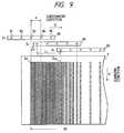
- the recording head 80 has N nozzles which are arranged in the subscanning direction at a pitch that is equal to a distance corresponding to P pixels.
- five nozzles 91 to 95 are arranged in the subscanning direction with one pixel set to be e.g. 84.7 ⁇ m (1/300 inches) and at a pitch that is equal to a distance corresponding to 8 pixels.
- the moving distance Z of the recording head 80 in the subscanning direction is set to be a distance corresponding to 3 pixels per one turn of the transfer drum 1.
- the recording head 80 is moved from the initial position S1 to a position indicated by S2 or by a distance corresponding e.g. to 3 pixels for every turn of the transfer drum 1.
- the Zth nozzle (i.e., the nozzle 93) of the recording head 80 counted from the upstream side of the subscanning direction is made coincident with an edge of a printing area 90 of the transfer drum 1, the ink image writing step is commenced so that an ink image is formed starting from an ink dot string R1 and at a pitch corresponding to 2 ink dot strings.
- the recording head 80 is moved to a position indicated by S3, or, when the nozzle 91 is observed, the nozzle 91 is moved to a position of an ink dot string R25.
- the position indicated by S3 can be expressed by the following expression in terms of the nozzle number N of the recording head, the nozzle pitch P, and the moving distance Z by which the recording head is moved per one turn of the transfer drum in the subscanning direction.
- LL (N - Z) ⁇ P + Z
- This value defines the moving distance of the recording head 80 which allows the nozzle 91 to be made coincident at the 9th turn of the transfer drum 1 with a position in a gap formed by scannings of the 1st to 8th turns of the transfer drum 1, and allows a continuous ink image to be formed in the printing area 90 without producing a double writing or a region where the writing is not conducted.
- Fig. 10 shows the relationship between the rotation of the transfer drum 1 and the moving distance of the recording head 80 in the subscanning direction.
- a desired ink image is formed in the printing area 90 by repeating movements in which the moving distance is Z in 1st to Pth turns, LL in a (P + 1)th turn, Z in (P + 2)th to (2 ⁇ P)th turns, LL in a ⁇ (2 ⁇ P) + 1 ⁇ th turn, ... .
- Z and P can be set so that Z/P is an irreducible fraction and a relationship of P ⁇ (M - 1) + 2 ⁇ Z ⁇ P ⁇ (M - 1) + P - 2 is satisfied when a minimum natural number M satisfying (Z/P) ⁇ M is defined.
- an ink image which is free from the repellent phenomenon can be formed by using a recording head shorter than the recording area of the transfer medium in the subscanning direction.
- ink drops are impacted onto a transfer medium which can conduct a low pressure transfer and has a high peeling property, in a discontinuous manner at least in the subscanning direction and as ink dot strings in the main scanning direction, and thereafter ink drops are impacted to positions which are not adjacent to ink dot strings formed immediately before the current scanning step. Therefore, the invention can attain an effect that the repellent phenomenon which may produce an unacceptably poor image quality is prevented from occurring so that an image of a high quality can be obtained on the transfer medium and therefore an image of a high quality can be obtained on the recording medium.
- Fig. 11 is a perspective view of an ink jet printer which is a sixth embodiment of the invention.
- An ink jet recording head 2, and a pressure roller 3 which functions as the transfer means are sequentially arranged around a transfer drum 1 which functions as the transfer medium.
- the recording head 2 is an ink jet recording head of the type which uses piezoelectric elements, and is supplied with ink from an ink reservoir 126 through an ink supply pipe 129.
- the recording head 2 has a plurality of nozzles which are arranged at equal intervals in the axial direction of the transfer drum 1. In the embodiment, the recording head 2 has 512 nozzles arranged at 0.677mm (16/600-inch) pitches.
- a head moving device 120 comprises a driving motor 121, a recording head holding member 125, and a movement guide 127.
- the recording head 2 fixed onto the recording head holding member 125 is moved by the driving motor 121 along the movement guide 127 in the axial direction of the transfer drum 1, by an arbitrary distance which is in units of e.g. 42.3 ⁇ m (1/600 inches), with 0.635mm (15/600 inches) as the maximum for each turn of the transfer drum 1.
- the transfer drum 1 is structured by laminating an elastic layer made of silicone rubber on the periphery of a metal pipe, and has a circumference of e.g. 25.4cm (10 inches).
- the transfer drum 1 is rotated by a drum driving motor 113.
- a sensor 115 detects a timing mark 114 attached on the transfer drum 1 and outputs a signal indicative of the rotating speed of the transfer drum 1.
- the sensor 115 generates as the output signal in the given example, one pulse per 42.3 ⁇ m (1/600 inches) or 6000 pulses for every turn of the transfer drum 1.
- 4,864 pulses are used for determining the printing timing of the recording head.
- the pressure roller 3 is a roller made of a metal such as aluminum, and is pressed against or released from the transfer drum 1 by a transfer pressure applying device 128.
- the roller rotates at the same speed as the peripheral speed of the transfer drum 1 in the direction of an arrow B in the figure while a recording sheet 5 is interposed between the roller and the drum.
- the transfer pressure is set to be in the range of 10 to 50 kgw.
- the image formation step consists of two steps, an image writing step of forming an ink image on the transfer drum 1, and a transfer step of transferring the ink image formed on the transfer drum to a recording sheet.
- the image writing step will be described with reference to Figs. 12 and 13.
- the recording area on the transfer drum 1 is divided e.g. into 16 regions for each nozzle of the recording head 2.
- the recording head 2 is positioned by the recording head moving device 120 so as to correspond to a block which is to be firstly recorded. While the transfer drum 1 conducts one turn in the direction of an arrow A, the nozzles (in Fig. 12, two nozzles 200 and 201 are representatively illustrated) then eject ink to form an ink image. In Fig.12, the ink image is shown by dot strings 202 and 203.
- the recording head 2 is moved to the next writing block in the direction of an arrow D or E in the unit of e.g. 42.3 ⁇ m (1/600 inches).
- the transfer drum 1 begins the second turn so that dot strings are formed on the transfer drum 1 in the same manner as the first turn. Since the nozzle pitch h is in this example 0.677mm (16/600 inches), the transfer drum 1 makes 16 turns in the same manner to form an image of one page on the transfer drum 1.
- a controller 130 develops the printing data in a memory 152, preferably a video memory in accordance with the printing instructions.
- the video memory 152 consists of 16 blocks in total. Each of the blocks has a capacity of about 2.5 megabits obtained by multiplying the total nozzle number of 512 by 4,864 dots which can be printed by one nozzle during one turn of the transfer drum 1.
- a dot counter 153 counts the number of printing dots of each of the writing blocks in the video memory 152, and informs the controller 130 of the counted values.
- the controller 130 decides the sequence of printing the blocks in order of decreasing counted value, and transfers information indicative of the sequence of the printing blocks to a memory selector 154. In deciding the sequence, however, restriction is set so that adjacent blocks are not successively subjected to the printing step.
- the memory selector 154 reads out printing data from the video memory 152 on the basis of the sequence information, and transfers the data to the recording head 2.
- the controller 130 causes a recording head moving device driver 155 to drive the recording head moving device 120 so as to conduct the positioning of the recording head.
- the sequence changing means is constituted by the controller 130.
- the transfer step After an image of one page has been formed on the transfer drum 1, the pressure roller 3 is pressed against the transfer drum 1. Timing is provided so that the recording start position corresponds to the leading portion of the recording sheet, and the recording sheet 5 is transported to the area where pressure roller 3 contacts transfer drum by sheet transporting means 141 (see Fig. 11), thereby starting the transfer step.
- sheet transporting means 141 see Fig. 11
- Fig. 15 is a side view of a color ink jet printer which is a seventh embodiment of the invention.
- Recording heads 2a to 2d and a transfer roller 3 are arranged around a transfer drum 1.
- the recording heads 2a to 2d can be independently moved by head moving devices 120a to 120d which can be structured in the same manner as the moving device of the sixth embodiment, respectively.
- the recording heads perform the color printing. Namely, the recording head 2a ejects ink of black, the recording head 2b ink of cyan, the recording head 2c ink of magenta, and the recording head 2d ink of yellow.
- the mechanisms for transporting a recording sheet 5 and conducting a switching operation of the pressure roller 3 can be structured in the same manner as those of the sixth embodiment.
- a controller 130a receives printing instructions and printing data from a host computer 116.
- the controller 130a develops the printing data in memories, which preferably are video memories 152a to 152d in accordance with the printing instructions.
- the memories are independently provided for respective colors.
- dot counters 153a to 153d count the number of printing dots of each of the printing blocks in the video memories 152a to 152d, and inform the controller 130a of the counted values.
- the controller 130a decides the printing sequence of the video memories 152a to 152d in order of decreasing number of printed dots. In deciding the sequence, restriction is set so that adjacent blocks are not successively subjected to the printing step for each color, and that the same block is not printed plural times in the same rotation of the transfer drum 1.
- the controller 130a transfers information indicative of the decided sequence, to memory selectors 154a to 154d.
- the memory selectors 154a to 154d read out printing data from the video memories 152a to 152d in the decided sequence in synchronization with the rotation of the transfer drum 1, and transfer the data to the respective recording heads 2a to 2d.
- the controller 130 controls the recording heads 2a to 2d so as to cause them to move to the respective blocks to be printed, by sending instructions to recording head moving device drivers 155a to 155d to drive the recording head moving devices 120a to 120d.
- the conditions under which an ink film is formed on a transfer medium are corrected by changing the sequence of writing blocks of printing data in accordance with the number of printing dots, thereby allowing recording with a high printing quality. Since adjacent blocks are not successively subjected to the printing step, ink coagulation can be prevented. In a color printing, ink mixing on the transfer medium is not conducted in the same turn of the transfer medium, thereby preventing enlargement of the dot diameter due to ink mixing before formation of the film and thus allowing recording having a high printing quality.
Abstract
Description
- The invention relates to an ink jet recording method and apparatus especially of a transfer type in which an ink image is formed on a transfer medium and then transferred to a recording medium to thereby obtain an ink image on the recording medium.
- A transfer type ink jet printer has the advantage that ink jet nozzles are free from clogging due to unintended contacts between a recording head and a recording sheet or due to paper dust. This advantage assures high reliability. Such transfer type ink jet printers are disclosed in U.S. Patent specifications Nos. 4,538,156 and 5,099,256.
- In the disclosed apparatuses, an ink jet recording head (hereinafter, referred to as a recording head) having a plurality of nozzles is separated from a cylindrical transfer medium by a gap. When an ink image is to be formed on the transfer medium by the recording head, the recording head forms an ink image on the cylinder in accordance with an image signal in synchronization with the rotation of the cylindrical transfer medium, while the recording head moves in a direction parallel to the direction in which the nozzles are arranged. Then a recording medium is brought into contact with the transfer medium and pressed from the back against the transfer medium, whereby the ink image is transferred to the recording medium. Thereafter, the recording medium is discharged from the apparatus.
- In another known method (Japanese Patent Publication (Kokai) No. HEI4-169,236), in order to dry and fix a recorded ink image to improve the printing quality, the total number of printed dots or the density of printed dots is counted, and a drying heater is controlled in accordance with the counted value.
- In any of the above apparatuses, the transfer step must be conducted at a low pressure to ensure high efficiency and complete transfer of the image. Specifically, the step of transferring an ink image from a transfer medium to a recording sheet is conducted by applying a pressure, and therefore the transfer medium must be made of a material from which the ink image is easily peeled or which has a low surface energy. On the other hand, the ink image on the transfer medium is formed by dots produced by ink drops ejected from the recording head. Because of surface tension, such dots have a tendency to gather on a material having a low surface energy. Therefore, plural dots aggregate on the transfer medium to form a large dot. As a result, a dot may be formed at a position different from where the dot should be formed, or an ink image formed by an aggregation of dots may be deformed. Hereinafter, this phenomenon is referred to as the repellent phenomenon.
- Fig. 1 schematically shows a typical example of the repellent phenomenon observed when an image is formed by groups of dots. In a prior art apparatus, a recording method is employed in which a
recording head 101 having a plurality ofnozzles 110 is moved in a subscanning direction indicated by an arrow U in the figure, so that dots are sequentially written from the initial position indicated by S1 to a position indicated by S2. According to this method,ink dot strings 103 are continuously sequentially overlapped on atransfer medium 102 starting from the side where the writing is initiated. The repellent phenomenon occurs more easily as the quantity of overlapping ink drops increases or as the ink amount per unit area increases. Moreover, the drying of the ink dot strings proceeds starting from the side where the writing is initiated. In anarea 104 close to an ink dot string written in an earlier stage, therefore, the repellent phenomenon does not occur. In anarea 105 where ink dot strings are written and the printing duty is high, conversely, there may arise a case where the repellent phenomenon occurs so that the area is divided intoportions 106 having ink andportions 107 having no ink. - Japanese Patent Publication (Kokuku) No. HEI4-19,030 discloses a recording method in which ink drops are directly impacted to a recording medium while ink dot strings are alternately written in forward and reverse paths on every other row in a direction perpendicular to a scanning direction of a recording head. When this recording method is applied to a transfer type ink jet recording apparatus, however, the transfer medium does not absorb water contained in the ink as does a recording sheet, so that before an ink dot string written in the immediately preceding scanning step is completely dried, an adjacent ink dot string is written. Therefore, the repellent phenomenon occurs on the transfer medium in the manner described above, resulting in an image having reduced quality.
- Also, in transfer type ink jet recording apparatuses having the above configurations, an ink image is formed while the cylindrical transfer medium makes plural turns. Therefore, the time required for forming a film of the ink image on the transfer medium varies so that the conditions of the film formation become uneven. This causes a transfer stain to be produced on a recording sheet, or causes the ink image on the transfer medium to remain partly untransferred, so that a high quality recording image cannot be obtained.
- In the case where the film-forming conditions are corrected by controlling a heater or the like in accordance with the density of printed dots, furthermore, it is impossible to control the energy applied to each dot, and therefore the correction cannot be conducted in a perfect manner.
- The invention has been conducted in view of the above-discussed problems. It is an object of the invention to provide an ink jet recording method and apparatus in which the repellent phenomenon that may produce an image of unacceptable quality is prevented from occurring on a transfer medium.
- This object is solved by the method of any one of
independent claims independent claims - The invention according to a preferred aspect provides an ink jet recording method and apparatus which conducts a low pressure transfer and has a high peeling property. Another aspect of this invention is to prevent variations in conditions under which a film is formed on a transfer medium from reducing the quality of a recording image formed on a recording medium.
- According to one aspect of the invention, an ink jet recording method for preventing the repellant phenomenon is provided in which an ink image writing step is conducted by selectively ejecting ink drops from a recording head, and comprises:
- a. a first scanning step in which ink dot strings are formed in a main scanning direction so as not to adjoin each other in at least a subscanning direction;
- b. a second scanning step in which the recording head is moved in the subscanning direction and ink drops are impacted to positions which are not adjacent to an ink dot string which is lastly formed on a transfer medium in the immediately preceding scanning step; and
- c. a step in which the second scanning step is repeated until a desired ink image is written.
- The ink jet recording apparatus according to this aspect of the invention is one in which an ink image is formed in an image recording step on a surface of a transfer medium, and the ink image is transferred to a recording medium in a transfer step to obtain the ink image, and which comprises:
a recording head having a plurality of ink ejecting nozzles which are arranged in a line at predetermined intervals;
a transfer medium which is opposed to the recording head and separated therefrom by a gap and rotatably supported, and on which an ink image is formed by the above-described ink jet recording method;
moving means for moving the recording head by a predetermined distance in a subscanning direction for every turn of the transfer medium; and
transfer means for transferring the ink image from the transfer medium to the recording medium. - According to the above method and apparatus, in the first scanning step, ink drops which are successively ejected from the recording head are impacted onto the transfer medium as ink dot strings in the main scanning direction and discontinuous in at least the subscanning direction. In the subsequent second scanning step, ink dot strings are impacted at positions which are not adjacent to the ink dot string which is the lastly formed one among the discontinuous ink dot strings impacted in the first scanning step. This produces results in which after the ink dot strings impacted in the first scanning step are sufficiently dried so that ink dots are fixed to respective predetermined positions, the ink dot strings of the second scanning step are impacted. Even when the impact of ink of the second scanning step is subsequently conducted, therefore, the repellent phenomenon does not occur.
- According to a further aspect of the invention, an ink jet recording apparatus is provided with an image writing means for forming an ink image on a surface of a transfer medium, and transfer means for transferring the ink image to a recording medium, and is characterized in that the apparatus further comprises:
dot counting means for counting the number of printing dots of image data stored in an image memory; and sequence changing means for changing a sequence in which a writing is conducted on the transfer medium in accordance with the number of printing dots which is counted by the dot counting means. - According to another embodiment of the invention, the above ink jet recording apparatus is further characterized in that the sequence changing means changes the sequence in such a manner that dot strings which are adjacent to each other on the transfer medium are not continuously printed.
- According to still another embodiment of the invention, the above ink jet recording apparatus is still further characterized in that, in a color image writing step using a plurality of recording heads, a dot in which two or more colors are to be mixed is not subjected to a plurality of printing steps in the same turn of a transfer medium.
- According to the above described proceeding configurations, the sequence of conducting a writing on the transfer medium is changed in accordance with the number of dots indicated by the printing data. Therefore, a block which has a large number of dots which requires a prolonged film formation time is subjected to an earlier writing step, and a block which has a small number of dots which requires a short film formation time is subjected to a later writing step, whereby the conditions of forming a film in each block in the transfer step can be made uniform. Since dot strings which are adjacent to each other on the transfer medium are not continuously subjected to the printing step, dot strings of each block are prevented from contacting each other before the film formation, so that ink coagulation does not occur. Since the same dot is not subjected to printing steps of plural recording heads during one turn of the transfer medium, the dot overlap is conducted after the film formation and therefore the enlargement of the dot diameter due to the increase in the amount of ink present is prevented from occurring.
- According to the invention, consequently, it is possible to configure an ink jet recording apparatus which can conduct recording with a high printing quality.
- Fig. 1 is a diagram illustrating deterioration of an ink image due to the repellent phenomenon on a transfer medium.
- Fig. 2 is a perspective view of an ink jet printer which is a first embodiment of the invention.
- Fig. 3 is a block diagram of a control system for controlling the operation of the ink image writing step in the first embodiment of the invention.
- Fig. 4 is a diagram illustrating a method of conducting a scanning of a recording head which is used in the first embodiment of the invention.
- Fig. 5 is a diagram showing an ink jet recording method in a second embodiment of the invention.
- Fig. 6 is a diagram showing an ink jet recording method in a third embodiment of the invention.
- Fig. 7 is a perspective view of a transfer type ink jet printer which is a fourth embodiment of the invention.
- Fig. 8 is a perspective view of a transfer type ink jet printer which is a fifth embodiment of the invention.
- Fig. 9 is a diagram showing an ink jet recording method in the fifth embodiment of the invention.
- Fig. 10 is diagram showing the relationship between the rotation of a transfer drum and the moving distance of a recording head in the fifth embodiment of the invention.
- Fig. 11 is a perspective view of an ink jet recording apparatus of a sixth embodiment of the invention.
- Fig. 12 is a perspective view showing the operation of moving a recording head of the ink jet recording apparatus of the sixth embodiment of the invention.
- Fig. 13 is a diagram showing a method of dividing the recording area of the ink jet recording apparatus of the sixth embodiment of the invention.
- Fig. 14 is a block diagram of the main portion of the ink jet recording apparatus of the sixth embodiment of the invention.
- Fig. 15 is a side view of an ink jet recording apparatus of a seventh embodiment of the invention.
- Fig. 16 is a block diagram of the main portion of the ink jet recording apparatus of the seventh embodiment of the invention.
- Hereinafter, the invention will be described in detail by illustrating embodiments.
- Fig. 2 is a perspective view of an ink jet printer which is a first embodiment of the invention. An ink
jet recording head 2 and apressure roller 3 which functions as the transfer means are sequentially arranged around atransfer drum 1 which functions as the transfer medium. The printer further comprises asheet supply device 6 for transporting arecording sheet 5 which functions as the recording medium to a portion where thepressure roller 3 is pressingly contacted with thetransfer drum 1, asheet discharging device 7 for discharging a recording sheet onto which an ink image has been transferred, and asheet discharge tray 8 for holding a dischargedrecording sheet 5. The rotation or moving directions of the members are indicated by arrows A, B, C, D and E, respectively. - The
recording head 2 preferably is an ink jet recording head of the type which uses piezoelectric elements, and has a plurality of nozzles which are arranged at equal intervals in the axial direction of thetransfer drum 1. In the embodiment, therecording head 2 has 512 nozzles arranged at 0.677mm (16/600-inch) pitches. Therecording head 2 is connected with anink reservoir 26 so as to be supplied with ink as required. Therecording head 2 is moved by movingmeans 20 in the direction of the arrow D, by a predetermined distance for every turn of thetransfer drum 1. - The moving means 20 is composed of a
lever 22 which is swingably attached so that alever shaft 23 functions as a fulcrum, and amotor 21. One end of thelever 22 is contacted with theshaft 21a of themotor 21, and the other end with an end of a recordinghead fixing member 25. Theshaft 21a of themotor 21 is threaded so as to be moved in the axial direction by the rotation of themotor 21. In the embodiment, theshaft 21a is moved by 0.5 mm for every turn of themotor 21 so that therecording head 2 is moved by 42.3µm (1/600 inches) in the direction of the arrow D against the force exerted by aspring 24 which is attached to the other end of the fixingmember 25. - The
transfer drum 1 is structured by laminating anelastic layer 12 made of silicone rubber on the periphery of ametal pipe 11. Preferably, the material of theelastic layer 12 is a rubber material from which an ink image is easily peeled, and includes fluorosilicone rubber, etc., in addition to silicone rubber. Thetransfer drum 1 is driven by adrum driving motor 13. The rotating speed of thetransfer drum 1 is controlled by a signal from arotary encoder 9 attached to thetransfer drum 1. The signal from therotary encoder 9 is used also as the references of the printing timing of the recording head and the rotation timing of the transfer drum. - The
pressure roller 3 is a roller made of a metal such as aluminum, and can be pressed against or released from thetransfer drum 1 by apressure applying device 10 through apressure lever 28 which swings about a supportingshaft 27. When thepressure roller 3 is pressed against thetransfer drum 1, the roller rotates at the same speed as the peripheral speed of thetransfer drum 1 in the direction of the arrow B in the figure while therecording sheet 5 is interposed between the roller and the drum. In the embodiment, the transfer pressure is set to be about 10 kgw. - The ink preferably contains at least water, a water soluble organic solvent, a pigment, and a colloidal dispersion resin. Specifically, a sample of the ink contains 3 wt% of carbon black as a pigment, 30 wt% of WATERSOL CD-540 (containing 40 % of a resin solid component and 13 % of isopropylene glycol) as a colloidal dispersion resin which is produced by DAINIPPON INK KAGAKU KOGYO and a colloidal dispersion of the modified epoxidized ester type, 5 wt% of triethanolamine as a water soluble organic solvent, and 5 wt% of polyethylene glycol as a humectant. The ink is prepared by adding purified water to these components.
- Next, operation of this embodiment will be described, starting with an ink image writing step.
- In an ink image writing step, the
pressure roller 3 is controlled so as to be separated from the surface of thetransfer drum 1. The rotation direction (the direction of the arrow A in the figure) of thetransfer drum 1 is defined as the main scanning direction, and the moving direction of therecording head 2 is defined as the subscanning direction. When thetransfer drum 1 makes one turn in the direction of the arrow A, ink dot strings are formed in a line at positions respectively corresponding to the nozzles of therecording head 2. Fig. 3 is a block diagram of a portion for controlling the operation of the ink image writing step in the embodiment. In accordance with the rotation of thetransfer drum 1, theencoder 9 generates the signal 9S at predetermined intervals. ACPU 30 receives the signal 9S and generates a timing signal 30S by which therecording head 2 is caused to eject ink drops. Adriver 31 drives therecording head 2 in accordance with the timing signal 30S and a printing signal 32S from asignal processing circuit 32. In parallel with this, theCPU 30 causes thedrum driving motor 13 for thetransfer drum 1 to rotate, and simultaneously sends a signal to the moving means 20 for the recording head so that therecording head 2 is moved by a predetermined distance.Printing data 34 transmitted from an external device are temporarily stored in abuffer memory 33, and sorted in accordance with the moving distance of therecording head 2 in the subscanning direction. Then theprinting data 34 are transmitted to thedriver 31 as the printing signal 32S through thesignal processing circuit 32. These operations are repeated so that ink dot strings are formed on thetransfer drum 1 as shown in Fig. 4. - Fig. 4 is a diagram illustrating a method of scanning the recording head which is used in the embodiment. For convenience of illustration, a
nozzle 40 will be described representatively in a case where ink dots are impacted in the whole of the printing area. First, therecording head 2 is located at the initial position indicated by S1 in the figure, and thetransfer drum 1 is rotated in the direction of the arrow A. As the first scanning step, ink dot strings L1, L3, L5 ... L15 are formed on thetransfer drum 1 in the subscanning direction at intervals of one ink dot string by ink drops which are selectively ejected from thenozzles 40. Therecording head 2 is moved by the moving means 20 by q (in the embodiment, q = 84.7µm (2/600) inches)) in the subscanning direction for every turn of thetransfer drum 1. In the first scanning step, thetransfer drum 1 makes 8 turns so that therecording head 2 is moved to the position S2. Although therecording head 2 is moved only in the subscanning direction, for convenience sake, positions of therecording head 2 indicated by S1 to S4 are shown being shifted in the main scanning direction. - In the subsequent second scanning step, the
recording head 2 is moved to the position S3, and an ink dot string L2 is formed between ink dot strings L1 and L3 which are written in the first scanning step. Similarly, ink dot strings L4, L6 ... L16 are formed between ink dot strings which are written in the first scanning step. The ink dot string L16 which is the endmost one of the ink dot strings formed by thenozzle 40 is written so as to be adjacent to an ink dot string M1 which is formed in the first scanning step by theadjacent nozzle 41, resulting in an ink image continuous in the subscanning direction being formed on thetransfer drum 1. - In the embodiment, as the second scanning step, ink dot strings are sequentially impacted to positions starting from those (the position of L2 for the nozzle 40) which are not adjacent to the ink dot strings (L15 for the nozzle 40) formed in the immediately preceding first scanning step. In other words, there is a sufficiently large time lag between the formation of ink dot strings in the first scanning step and the impact of ink drops between the ink dot strings in the second scanning step. This time lag is equal to the period from the start of the first scanning step to that of the second scanning step, and therefore sufficient for ink dot strings formed in the first scanning step to be dried. Consequently, ink dots impacted in the first scanning step are condensed before the start of the second scanning step, so as to have a high viscosity. Even when ink drops are impacted in the second scanning step to form a continuous ink image, therefore, the ink dots are fixed to respective predetermined positions and do not move. This prevents the repellent phenomenon from occurring and allows an ink image of a high quality to be formed on the transfer drum.
- Next, the transfer step will be described. In the transfer step, the
pressure applying device 10 is driven according to a predetermined timing so that thepressure roller 3 is controlled to be pressed against thetransfer drum 1 by thepressure lever 28 which uses the supportingshaft 27 as a swing shaft. The ink image carried on thetransfer drum 1 is moved as the drum is rotated and reaches the portion where thepressure roller 3 is pressed against thetransfer drum 1. At this time, therecording sheet 5 is transported by thesheet supply device 6 so as to contact thetransfer drum 1, and a pressure is applied bypressure roller 3 so that the ink image on thetransfer drum 1 is transferred to therecording sheet 5. Since theelastic layer 12 of thetransfer drum 1 has properties which allow an ink image to be easily peeled off, the ink image on thetransfer drum 1 is transferred to therecording sheet 5 in a substantially perfect manner. Therecording sheet 5 to which the ink image has been transferred is discharged by thesheet discharging device 7 to thesheet discharge tray 8 to be held thereon. - Next, an ink jet recording method of a second embodiment of the invention will be described with reference to Fig. 5. This embodiment is different from the first embodiment in that a recording head is moved in one subscanning direction to form an ink image. The ink is preferably obtained by dispersing a pigment and additives such as an emulsion and a surfactant into purified water which functions as an ink solvent. Specifically, the ink contains 1.5 wt% of carbon black as a pigment, 15 wt% of a styrene-acrylic copolymer emulsion as an emulsion, 6 wt% of diethylene glycol as a humectant, 10 to 20 wt% of sugar, 3 wt% of a surfactant, and several wt% of appropriate additives such as a preservative.
- An apparatus for executing the recording method has the same configuration as that of the first embodiment, and therefore only the ink image writing step will be described. The
recording head 2 has 513nozzles printing area 60 in the subscanning direction. At least onenozzle 70 is disposed in a region outside theprinting area 60. At the initial position of therecording head 2 indicated by S1, thenozzle 71 is positioned so as to coincide with an edge of theprinting area 60 and thetransfer drum 1 is rotated in the main scanning direction indicated by the arrow A, so that ink dot strings E1, F1, G1 ... are written at positions respectively corresponding to the nozzles. Therecording head 2 is moved in the subscanning direction D from the initial position to a position indicated by S2, with a pitch which is equal to a distance corresponding to two pixels (in the embodiment, one pixel corresponds to one ink dot and pixels are arranged in the unit of e.g. 84.7µm (1/300 inches)) for one turn of thetransfer drum 1, whereby an ink image can be formed at intervals of one ink dot string. Next, therecording head 2 is moved by a distance corresponding to 3 pixels in the subscanning direction, and ink dot strings are then written between two ink dot strings which were formed by the respective nozzles positioned at the downstream side in the subscanning direction. The position of therecording head 2 at this time is indicated by S3. When thenozzle 71 is observed, thenozzle 71 forms an ink image in the sequence of ink dot strings E1, E3, E5, and E7 at intervals of one ink dot string, and is then moved by a distance corresponding to 3 pixels in the subscanning direction, to form an ink dot string F2. Since thenozzle 70 is disposed outside theprinting area 60 and in the upstream side of the subscanning direction, an ink dot string E2 is written by thenozzle 70 having an initial position which is not within the printing area. - Thereafter, the
recording head 2 is moved by a distance corresponding to 2 pixels in the subscanning direction, and forms ink dot strings between ink dot strings which were previously formed, to write a continuous ink image in theprinting area 60. In the embodiment, the scanning in one direction is realized by disposing at least onenozzle 70 outside theprinting area 60, and changing halfway the pitch of movement of therecording head 2 in the subscanning direction. It is a matter of course that, according to this method, an ink image can be formed while the repellent phenomenon is prevented from occurring in the same manner as the first embodiment. Furthermore, it is not necessary to change the movement direction of the moving means, and therefore the recording head can be moved in the subscanning direction with an accuracy higher than that of the first embodiment so that an image of a higher quality is formed on the transfer medium. - A third embodiment of the invention will be described with reference to Fig. 6. Fig. 6 is a diagram illustrating the step of writing an ink image in the third embodiment of the invention. In the embodiment, a recording head is moved in one subscanning direction with a fixed pitch and ink drops are impacted to positions which are not adjacent to an ink dot string which has been formed in the immediately preceding scanning step, thereby forming a desired ink image on a transfer medium. The configuration of the apparatus is the same as that of the first embodiment, and therefore the description is concentrated on the ink image writing step.
- The
recording head 2 is structured so that one pixel is set to be e.g. 84.7µm (1/300 inches), and has 514 nozzles H1, H2, H3 ... H514 arranged at a pitch of P pixels. When thetransfer drum 1 makes one turn in the direction of the arrow A, ink dot strings are formed on thetransfer drum 1 in a line at positions respectively corresponding to the nozzles of therecording head 2. The moving means 20 is controlled so that, for every turn of thetransfer drum 1, therecording head 2 is moved in the subscanning direction by a distance equal to that corresponding to Z pixels. In the embodiment, P is set to be a distance equal to that corresponding to 8 pixels and Z is set to be a distance equal to that corresponding to 3 pixels. - At the initial position of the
recording head 2 indicated by S1, the nozzle H3 is positioned so as to coincide with the printing start position which is the left edge of theprinting area 50 of thetransfer drum 1. Under this condition, ink is ejected from the nozzles H3, H4, H5 ... to form ink dot strings O1, P1, Q1 ... on thetransfer drum 1. Then therecording head 2 is moved by a distance corresponding to Z pixels and ink drops are ejected. This position is indicated by S2. Under this condition, ink dot strings O4, P4, Q4 ... are formed on thetransfer drum 1. In this way, for every turn of thetransfer drum 1, therecording head 2 is moved in the subscanning direction by a distance corresponding to 3 pixels to sequentially form ink dot strings, and thetransfer drum 1 makes 8 turns so that a desired ink image is formed in theprinting area 50. - With respect to the ink dot strings O1 to O8, the ink dot strings are arranged in the order of their formation time and are shown together with a nozzle number in parentheses by which the respective ink dot string is formed, as follows: O1(H3), O4(H3), O7(H3), O2(H2), O5(H2), O8(H2), O3(H1), and O6(H1). A nozzle(s) which is caused by the scanning of the
recording head 2 to fall outside theprinting area 50, for example, the nozzles H1 and H2 in the first scanning, do not eject ink and are inhibited from ejecting ink until the nozzles are moved into theprinting area 50. - The relationship between the nozzle pitch P and the moving distance Z will be described. If Z/P is not an irreducible fraction, when the
recording head 2 is repeatedly moved several times in the subscanning direction, the positions of the nozzles begin to coincide with those which were previously scanned, resulting in the formation of ink dot strings being conducted twice at the same positions on thetransfer drum 1. When P is set to be a distance equal to that corresponding to 8 pixels and Z is set to be a distance equal to that corresponding to 2 pixels, for example, the above-mentioned coincidence is realized at a fifth turn of thetransfer drum 1. In order to ensure therecording head 2 will always scan positions which are not coincident with those previously scanned, P and Z must be set so that Z/P is an irreducible fraction. - In order to form ink dot strings at positions which are not adjacent to ink dot strings that are formed in the immediately preceding scanning step, the relationship of 2 ≦ Z ≦ P - 2 must be satisfied. In other words, when Z = 1 or

- Next the position of the nozzle which is at the edge of the
printing area 50 will be described. In order that ink dots are written by conducting the scanning of therecording head 2 with a fixed pitch in one direction without leaving space between them in an edge region of theprinting area 50 indicated by O1 to O8, at least Z - 1 nozzle(s) must be disposed outside the region which is located in the upstream side of the subscanning direction and outside the printing area. Since therecording head 2 is moved with a pitch of Z pixels, this results in regions which are continuous and constitute a part of theprinting area 50 being formed by means of at least Z nozzles. In other words, the subscanning of the recording head must be commenced when at least the Zth nozzle counted from the upstream side of the subscanning direction is made coincident with an edge of the printing area. - In summary, when Z and P are set so that Z/P is an irreducible fraction and the relationship of 2 ≦ Z ≦ P - 2 is satisfied, and the Zth nozzle counted from the upstream side of the subscanning direction is made coincident with an edge of the printing area, the movement of the recording head in one direction with a fixed pitch allows ink drops to be impacted to positions which are not adjacent to ink dot strings of the immediately preceding scanning step. Therefore, the repellent phenomenon can be prevented from occurring so that an image of a higher quality is formed on the transfer medium. According to the embodiment, the recording head can be moved in one direction with a fixed pitch, and therefore factors such as a back lash which may cause the moving means to fluctuate can be eliminated so that the movement accuracy is further enhanced, thereby realizing a higher image quality. Since regions which are continuous and constitute a part of the printing area are alternately formed by means of at least Z nozzles, the further effect of lowering deterioration of image quality due to variations between nozzles, such as those in weight and speed of ink drops, is attained. The transfer step is conducted in the same manner as that of the first embodiment, and therefore its description is omitted.
- Next, as a fourth embodiment, Fig. 7 shows a transfer type ink jet printer which can form an ink image while more effectively preventing the repellent phenomenon from occurring. The embodiment is different from the above-described embodiments in that heating means 4 incorporating a heater lamp is disposed in the periphery of the
transfer drum 1 so that the drying of an ink image formed on thetransfer drum 1 is accelerated. In advance of the ink image writing step, the surface of thetransfer drum 1 is controlled by the heating means 4 and temperature detecting means (not shown) so as to be within a temperature range in which some content of water contained in an ink image can be evaporated and the ink image can be maintained in an appropriately dry state. In the embodiment, the surface is controlled so as to be 55 ± 5°C. - In the ink image writing step, as illustrated in the first and second embodiments, ink dot strings are formed in the main scanning direction without adjoining each other at least in the subscanning direction. Under this condition, the surface of the
transfer drum 1 is already heated. Therefore, the drying of impacted ink drops is accelerated as thetransfer drum 1 rotates so that ink dots are easily fixed to predetermined positions. Even when a continuous ink image is formed by impacting ink drops in the subsequent second scanning step, consequently, the repellent phenomenon is prevented from occurring so that an ink image of a high quality is easily formed. Accordingly, the acceleration of the drying of ink drops enhances the recording speed, whereby an ink image of a high quality can be formed rapidly on a transfer medium without causing the repellent phenomenon. The transfer step is conducted in the same manner as that of the first embodiment, and therefore its description is omitted. - Next, a fifth embodiment of the invention will be described with reference to Figs. 8 to 10. The embodiment is configured so that a recording area is scanned plural times by a recording head shorter than the recording area while ink drops are impacted to positions which are not adjacent to ink dot strings of the immediately preceding scanning step, thereby forming a desired ink image. Fig. 8 is a perspective view of an ink jet printer and illustrates the embodiment. A
recording head 80 and an ink tank which is integrated with the head are held by a threadedcarriage shaft 81. Thecarriage shaft 81 is rotated by amotor 82 which functions as the moving means, so as to move therecording head 80 by a predetermined distance in the subscanning direction indicated by an arrow D. The other components of the embodiment are configured in the same manner as those of the first embodiment, and therefore their description is omitted. - The ink image writing step will be described. The
recording head 80 has N nozzles which are arranged in the subscanning direction at a pitch that is equal to a distance corresponding to P pixels. In the embodiment, fivenozzles 91 to 95 are arranged in the subscanning direction with one pixel set to be e.g. 84.7µm (1/300 inches) and at a pitch that is equal to a distance corresponding to 8 pixels. The moving distance Z of therecording head 80 in the subscanning direction is set to be a distance corresponding to 3 pixels per one turn of thetransfer drum 1. During the period in which thetransfer drum 1 makes P turns (1st to 8th turns), therecording head 80 is moved from the initial position S1 to a position indicated by S2 or by a distance corresponding e.g. to 3 pixels for every turn of thetransfer drum 1. When the Zth nozzle (i.e., the nozzle 93) of therecording head 80 counted from the upstream side of the subscanning direction is made coincident with an edge of aprinting area 90 of thetransfer drum 1, the ink image writing step is commenced so that an ink image is formed starting from an ink dot string R1 and at a pitch corresponding to 2 ink dot strings. Then therecording head 80 is moved to a position indicated by S3, or, when thenozzle 91 is observed, thenozzle 91 is moved to a position of an ink dot string R25. When the moving distance from S2 is represented by LL, the position indicated by S3 can be expressed by the following expression in terms of the nozzle number N of the recording head, the nozzle pitch P, and the moving distance Z by which the recording head is moved per one turn of the transfer drum in the subscanning direction.

In the embodiment, since N = 5, Z = 3, and P = 8, LL is equal to 19
recording head 80 which allows thenozzle 91 to be made coincident at the 9th turn of thetransfer drum 1 with a position in a gap formed by scannings of the 1st to 8th turns of thetransfer drum 1, and allows a continuous ink image to be formed in theprinting area 90 without producing a double writing or a region where the writing is not conducted. Fig. 10 shows the relationship between the rotation of thetransfer drum 1 and the moving distance of therecording head 80 in the subscanning direction. In the embodiment, a desired ink image is formed in theprinting area 90 by repeating movements in which the moving distance is Z in 1st to Pth turns, LL in a (P + 1)th turn, Z in (P + 2)th to (2 × P)th turns, LL in a {(2 × P) + 1}th turn, .... - During the 1st to Pth turns of the
transfer drum 1, the scanning is conducted with a fixed pitch in one subscanning direction. In order that ink drops are impacted to positions which are not adjacent to ink dot strings formed in the immediately preceding scanning step, as described in conjunction with the third embodiment, Z and P must be set so that Z/P is an irreducible fraction and the relationship of 2 ≦ Z ≦ P - 2 is satisfied. However, this relationship is applied to the case of Z/P < 1. Generally, Z and P can be set so that Z/P is an irreducible fraction and a relationship of P × (M - 1) + 2 ≦ Z ≦ P × (M - 1) + P - 2 is satisfied when a minimum natural number M satisfying (Z/P) < M is defined. - In the case where N is equal to Z


motor 82 can be constant so that a scanning of high accuracy is realized, thereby enabling an ink image free from the repellent phenomenon and high in quality to be formed on the transfer medium. The transfer step is conducted in the same manner as that of the first embodiment, and therefore its description is omitted. - According to the embodiment, an ink image which is free from the repellent phenomenon can be formed by using a recording head shorter than the recording area of the transfer medium in the subscanning direction.
- According to the above embodiments, ink drops are impacted onto a transfer medium which can conduct a low pressure transfer and has a high peeling property, in a discontinuous manner at least in the subscanning direction and as ink dot strings in the main scanning direction, and thereafter ink drops are impacted to positions which are not adjacent to ink dot strings formed immediately before the current scanning step. Therefore, the invention can attain an effect that the repellent phenomenon which may produce an unacceptably poor image quality is prevented from occurring so that an image of a high quality can be obtained on the transfer medium and therefore an image of a high quality can be obtained on the recording medium.
- Fig. 11 is a perspective view of an ink jet printer which is a sixth embodiment of the invention. An ink
jet recording head 2, and apressure roller 3 which functions as the transfer means are sequentially arranged around atransfer drum 1 which functions as the transfer medium. - The
recording head 2 is an ink jet recording head of the type which uses piezoelectric elements, and is supplied with ink from anink reservoir 126 through anink supply pipe 129. Therecording head 2 has a plurality of nozzles which are arranged at equal intervals in the axial direction of thetransfer drum 1. In the embodiment, therecording head 2 has 512 nozzles arranged at 0.677mm (16/600-inch) pitches. - A
head moving device 120 comprises a drivingmotor 121, a recordinghead holding member 125, and amovement guide 127. Therecording head 2 fixed onto the recordinghead holding member 125 is moved by the drivingmotor 121 along themovement guide 127 in the axial direction of thetransfer drum 1, by an arbitrary distance which is in units of e.g. 42.3µm (1/600 inches), with 0.635mm (15/600 inches) as the maximum for each turn of thetransfer drum 1. - The
transfer drum 1 is structured by laminating an elastic layer made of silicone rubber on the periphery of a metal pipe, and has a circumference of e.g. 25.4cm (10 inches). Thetransfer drum 1 is rotated by adrum driving motor 113. Asensor 115 detects atiming mark 114 attached on thetransfer drum 1 and outputs a signal indicative of the rotating speed of thetransfer drum 1. Specifically, thesensor 115 generates as the output signal in the given example, one pulse per 42.3µm (1/600 inches) or 6000 pulses for every turn of thetransfer drum 1. Among these pulses, 4,864 pulses are used for determining the printing timing of the recording head. - The
pressure roller 3 is a roller made of a metal such as aluminum, and is pressed against or released from thetransfer drum 1 by a transferpressure applying device 128. When thepressure roller 3 is pressed against thetransfer drum 1, the roller rotates at the same speed as the peripheral speed of thetransfer drum 1 in the direction of an arrow B in the figure while arecording sheet 5 is interposed between the roller and the drum. In the embodiment, the transfer pressure is set to be in the range of 10 to 50 kgw. - Next, the operation will be described. The image formation step consists of two steps, an image writing step of forming an ink image on the
transfer drum 1, and a transfer step of transferring the ink image formed on the transfer drum to a recording sheet. - The image writing step will be described with reference to Figs. 12 and 13. The recording area on the
transfer drum 1 is divided e.g. into 16 regions for each nozzle of therecording head 2. Therecording head 2 is positioned by the recordinghead moving device 120 so as to correspond to a block which is to be firstly recorded. While thetransfer drum 1 conducts one turn in the direction of an arrow A, the nozzles (in Fig. 12, two nozzles 200 and 201 are representatively illustrated) then eject ink to form an ink image. In Fig.12, the ink image is shown by dot strings 202 and 203. After the writing step for one turn has been conducted on thetransfer drum 1, therecording head 2 is moved to the next writing block in the direction of an arrow D or E in the unit of e.g. 42.3µm (1/600 inches). Thetransfer drum 1 begins the second turn so that dot strings are formed on thetransfer drum 1 in the same manner as the first turn. Since the nozzle pitch h is in this example 0.677mm (16/600 inches), thetransfer drum 1 makes 16 turns in the same manner to form an image of one page on thetransfer drum 1. - The method of deciding the sequence of the writing blocks will be described with reference to Fig. 14. First, printing instructions and printing data are transmitted from a
host computer 116. Then acontroller 130 develops the printing data in amemory 152, preferably a video memory in accordance with the printing instructions. Thevideo memory 152 consists of 16 blocks in total. Each of the blocks has a capacity of about 2.5 megabits obtained by multiplying the total nozzle number of 512 by 4,864 dots which can be printed by one nozzle during one turn of thetransfer drum 1. When data of one page have been developed, adot counter 153 counts the number of printing dots of each of the writing blocks in thevideo memory 152, and informs thecontroller 130 of the counted values. Thecontroller 130 decides the sequence of printing the blocks in order of decreasing counted value, and transfers information indicative of the sequence of the printing blocks to amemory selector 154. In deciding the sequence, however, restriction is set so that adjacent blocks are not successively subjected to the printing step. Thememory selector 154 reads out printing data from thevideo memory 152 on the basis of the sequence information, and transfers the data to therecording head 2. In accordance with the sequence of the printing blocks, thecontroller 130 causes a recording head movingdevice driver 155 to drive the recordinghead moving device 120 so as to conduct the positioning of the recording head. In the embodiment, the sequence changing means is constituted by thecontroller 130. - Next, the transfer step will be described. After an image of one page has been formed on the
transfer drum 1, thepressure roller 3 is pressed against thetransfer drum 1. Timing is provided so that the recording start position corresponds to the leading portion of the recording sheet, and therecording sheet 5 is transported to the area wherepressure roller 3 contacts transfer drum by sheet transporting means 141 (see Fig. 11), thereby starting the transfer step. When the end portion of therecording sheet 5 has been subjected to the transfer step and passes through the area of contact betweenpressure roller 3 and transferdrum 1, thepressure roller 3 is separated from thetransfer drum 1 so that therecording sheet 5 is discharged. - As a result of the above steps, the recording of one page is completed.
- Fig. 15 is a side view of a color ink jet printer which is a seventh embodiment of the invention. Recording heads 2a to 2d and a
transfer roller 3 are arranged around atransfer drum 1. The recording heads 2a to 2d can be independently moved byhead moving devices 120a to 120d which can be structured in the same manner as the moving device of the sixth embodiment, respectively. The recording heads perform the color printing. Namely, therecording head 2a ejects ink of black, therecording head 2b ink of cyan, therecording head 2c ink of magenta, and therecording head 2d ink of yellow. The mechanisms for transporting arecording sheet 5 and conducting a switching operation of thepressure roller 3 can be structured in the same manner as those of the sixth embodiment. - The operation of the printer will be described with reference to Fig. 16. A
controller 130a receives printing instructions and printing data from ahost computer 116. Thecontroller 130a develops the printing data in memories, which preferably arevideo memories 152a to 152d in accordance with the printing instructions. - The memories are independently provided for respective colors. When data of one page have been developed, dot counters 153a to 153d count the number of printing dots of each of the printing blocks in the
video memories 152a to 152d, and inform thecontroller 130a of the counted values. Thecontroller 130a decides the printing sequence of thevideo memories 152a to 152d in order of decreasing number of printed dots. In deciding the sequence, restriction is set so that adjacent blocks are not successively subjected to the printing step for each color, and that the same block is not printed plural times in the same rotation of thetransfer drum 1. Thecontroller 130a transfers information indicative of the decided sequence, tomemory selectors 154a to 154d. Thememory selectors 154a to 154d read out printing data from thevideo memories 152a to 152d in the decided sequence in synchronization with the rotation of thetransfer drum 1, and transfer the data to the respective recording heads 2a to 2d. Thecontroller 130 controls the recording heads 2a to 2d so as to cause them to move to the respective blocks to be printed, by sending instructions to recording head movingdevice drivers 155a to 155d to drive the recordinghead moving devices 120a to 120d. - According to the embodiment, the conditions under which an ink film is formed on a transfer medium are corrected by changing the sequence of writing blocks of printing data in accordance with the number of printing dots, thereby allowing recording with a high printing quality. Since adjacent blocks are not successively subjected to the printing step, ink coagulation can be prevented. In a color printing, ink mixing on the transfer medium is not conducted in the same turn of the transfer medium, thereby preventing enlargement of the dot diameter due to ink mixing before formation of the film and thus allowing recording having a high printing quality.
- In the above, embodiments having an ink jet recording head which uses piezoelectric elements have been described. The invention is not restricted to this, and a recording head using heating elements may be employed. Also e.g. belt type transfer medium may be used in place of a drum transfer medium.
Claims (13)
- An ink jet recording method in which an ink image is written on a transfer medium by a recording head and transferred to a recording medium, said recording head being opposed to said transfer medium and separated therefrom by a gap, and a main scanning and a subscanning are conducted on said transfer medium, wherein an ink image writing step is conducted by selectively ejecting ink drops from said recording head, said ink image writing step comprising:a) a first scanning step in which ink dot strings are formed in a main scanning direction so as not to adjoin each other in at least a subscanning direction;b) a second scanning step in which said recording head is moved in the subscanning direction and ink drops are impacted to positions which are not adjacent to an ink dot string which is lastly formed on said transfer medium in an immediately preceding scanning step; andc) a step in which said second scanning step is repeated until a desired ink image is written.
- An ink jet recording method according to claim 1, wherein ink dot strings which are adjacent to each other on said transfer medium in the subscanning direction are formed by ink drops ejected from different nozzles of said recording head.
- An ink jet recording method, especially according to any one of the preceding claims, in which an ink image is written on a transfer medium by a recording head and transferred to a recording medium, said recording head being opposed to said transfer medium and separated therefrom by a gap, and a main scanning and a subscanning are conducted on said transfer medium, wherein an ink image writing step is conducted by using a recording head having a plurality of nozzles which are separated by a gap corresponding to P pixels in a subscanning direction, said ink image writing step comprising:a) a first scanning step in which, for each main scanning, ink dot strings are written by moving said recording head in one subscanning direction by a distance corresponding to Z pixels Z/P being an irreducible fraction, a relationship of 2 ≦ Z ≦ P - 2 being satisfied; andb) a step in which said first scanning step is repeated until a desired ink image is written.
- An ink jet recording method according to claim 3, wherein, in said ink image writing step, the subscanning of said reocrding head is commenced when at least Zth nozzle counted from an upstream side of the subscanning direction of said recording head is made coincident with an edge of a printing area.
- An ink jet recording method, especially according to any one of the preceding claims, in which an ink image is written on a transfer medium by a recording head and transferred to said transfer medium, said recording head being opposed to a recording medium and separated therefrom by a gap, and a main scanning and a subscanning are conducted on said transfer medium, wherein an ink image writing step is conducted by using a recording head having N (N is a natural number and N ≧ 2) nozzles which are separated by a gap corresponding to P pixels in a subscanning direction, said ink image writing step comprising:a) a first scanning step in which, in a period from a start of a printing to Pth main scanning, ink dot strings are formed by, for each main scanning, moving said recording head in one subscanning direction by a distance corresponding to Z pixels, Z/P being an irreducible fraction, a relationship of P x (M - 1) + 2 ≦ Z ≦ P x (M - 1) + P - 2 being satisfied when a minimum natural number M satisfying (Z/P) < M is defined;b) a second scanning step in which, in a (P + 1)th main scanning, said recording head is moved in one subscanning direction by a distance equal to (N - Z) x P + Z pixels; andc) a step in which said first and second scanning steps are alternatively repeated until a desired ink image is written.
- An ink jet recording method according to claim 5, wherein N is equal to Z

- An ink jet recording apparatus in which an ink image is formed in an image recording step on a surface of a transfer medium (1), and the ink image is transferred to a recording medium (5) in a transfer step, said apparatus comprising:
a recording head (2) having a plurality of ink ejecting nozzles (H1, H2, H3 ...) which are arranged in a line at predetermine intervals;
a transfer medium (12) which is opposed to said recording head (2) and separated therefrom by a gap and rotatably supported, and on which an ink image is formed preferably by an ink jet recording method according to any one of claims 1 to 6;
moving means (20) for moving said recording head (2) by a predetermined distance in a subscanning direction for every turn of said transfer medium (12); and
transfer means (3) for transferring the ink image on said transfer medium (12) to said recording medium (5). - An ink jet recording apparatus according to claim 7, wherein said apparatus further comprises heating means (4) for heating the ink image written onto said transfer medium (12).
- An ink jet recording apparatus, especially according to claim 6 or 9, comprising:
image writing means (2) for forming an ink image on a surface of a transfer medium (12);
transfer means (3) for transferring the ink image to a recording medium (5);
dot counting means (153; 153a to 153d) for counting a number of printing dots of image data stored in an image memory (152; 152a to 152d); and
sequence changing means for changing a sequence of conducting a writing on said transfer medium in accordance with the number of printing dots which is counted by said dot counting means. - An ink jet recording apparatus according to claim 9, wherein said sequence changing means changes the sequence in such a manner that dot strings which are adjacent to each other on said transfer medium are not continuously printed.
- An ink jet apparatus according to claim 9 or 10, wherein said image writing means comprises a recording head (2), and said transfer means comprises a pressure roller (3).
- A color ink jet recording apparatus, especially according to any one of claims 7 to 11, comprising:
image writing means having a plurality of recording heads (2a to 2d) for forming an ink image on a surface of a transfer medium (12);
transfer means (3) for transferring the ink image to a recording medium (5);
dot counting means (153a to 153d) for counting a number of printing dots of image data stored in an image memory; and sequence changing means for changing a sequence of conducting a writing on said transfer medium in accordance with the number of printing dots, and for changing the sequence in such a manner that a dot in which two or more colors are to be mixed is not subjected to a plurality of printing steps in a same turn of said transfer medium. - An ink jet color recording method comprising the steps of:
receiving printing instructions and first printing data;
developing second printing data in a plurality of memories, preferably video memories, according to printing blocks in accordance with the printing instructions and the first printing data, each of said plurality of memories associated with a respective color;
counting a number of printing dots of each of the printing blocks represented by said second printing data;
deciding a printing sequence of said printing blocks in order of decreasing number of dots, wherein said deciding is restricted so that adjacent ones of said printing blocks are not successively printed.
Applications Claiming Priority (6)
| Application Number | Priority Date | Filing Date | Title |
|---|---|---|---|
| JP194954/93 | 1993-08-05 | ||
| JP19495293A JPH0747669A (en) | 1993-08-05 | 1993-08-05 | Ink jet recording apparatus |
| JP19495493 | 1993-08-05 | ||
| JP194952/93 | 1993-08-05 | ||
| JP5194954A JPH0747759A (en) | 1993-08-05 | 1993-08-05 | Ink jet recording method and ink jet recorder |
| JP19495293 | 1993-08-05 |
Publications (3)
| Publication Number | Publication Date |
|---|---|
| EP0638423A2 true EP0638423A2 (en) | 1995-02-15 |
| EP0638423A3 EP0638423A3 (en) | 1995-11-22 |
| EP0638423B1 EP0638423B1 (en) | 1999-11-10 |
Family
ID=26508829
Family Applications (1)
| Application Number | Title | Priority Date | Filing Date |
|---|---|---|---|
| EP94112289A Expired - Lifetime EP0638423B1 (en) | 1993-08-05 | 1994-08-05 | Ink jet recording method |
Country Status (4)
| Country | Link |
|---|---|
| US (2) | US5760807A (en) |
| EP (1) | EP0638423B1 (en) |
| DE (1) | DE69421576T2 (en) |
| SG (1) | SG69958A1 (en) |
Cited By (4)
| Publication number | Priority date | Publication date | Assignee | Title |
|---|---|---|---|---|
| EP0665114A2 (en) * | 1994-01-31 | 1995-08-02 | Tektronix, Inc. | Ink jet print head array and interlace printing method |
| FR2741296A1 (en) * | 1995-11-17 | 1997-05-23 | Chapel Reprographie | High speed ink-jet printer |
| US6354701B2 (en) | 1995-11-23 | 2002-03-12 | Aprion Digital Ltd. | Apparatus and method for printing |
| WO2007131753A1 (en) * | 2006-05-16 | 2007-11-22 | Rehau Ag + Co | Device and procedure for imprinting an endless substrate with a pattern |
Families Citing this family (10)
| Publication number | Priority date | Publication date | Assignee | Title |
|---|---|---|---|---|
| US5988790A (en) * | 1996-04-11 | 1999-11-23 | Mitsubishi Denki Kabushiki Kaisha | Multiple element printer and method of adjusting thereof |
| US6604806B1 (en) | 1999-10-20 | 2003-08-12 | Canon Kabushiki Kaisha | High resolution printing |
| US6247786B1 (en) | 1999-10-26 | 2001-06-19 | Lexmark International, Inc. | Dynamic pass buffer sizing |
| US6609781B2 (en) | 2000-12-13 | 2003-08-26 | Lexmark International, Inc. | Printer system with encoder filtering arrangement and method for high frequency error reduction |
| US7270407B2 (en) * | 2001-06-29 | 2007-09-18 | Hewlett-Packard Development Company, L.P. | Methods for digitally printing on ceramics |
| US7052125B2 (en) | 2003-08-28 | 2006-05-30 | Lexmark International, Inc. | Apparatus and method for ink-jet printing onto an intermediate drum in a helical pattern |
| US7621631B2 (en) * | 2004-02-04 | 2009-11-24 | Hewlett-Packard Development Company, L.P. | Enhancing color space of reactive ink using heat |
| US7114799B2 (en) * | 2004-07-09 | 2006-10-03 | Hewlett-Packard Development Company, L.P. | Printing ink delivery control mechanism |
| KR100911143B1 (en) * | 2004-10-18 | 2009-08-06 | 삼성전자주식회사 | Method and apparatus for controling printing order, image forming device using the method |
| US7654663B2 (en) * | 2005-09-30 | 2010-02-02 | Xerox Corporation | Transfix roller load controlled by motor current |
Citations (10)
| Publication number | Priority date | Publication date | Assignee | Title |
|---|---|---|---|---|
| EP0076948A2 (en) * | 1981-10-08 | 1983-04-20 | International Business Machines Corporation | Variable resolution interlaced ink jet printer |
| JPS58194541A (en) * | 1982-05-11 | 1983-11-12 | Canon Inc | Recording method |
| US4538156A (en) * | 1983-05-23 | 1985-08-27 | At&T Teletype Corporation | Ink jet printer |
| US4595948A (en) * | 1982-10-13 | 1986-06-17 | Ricoh Company, Ltd. | Multicolor ink jet recording apparatus having means for preventing blurring of ink |
| DE3620334A1 (en) * | 1985-06-21 | 1987-01-02 | Sharp Kk | PRINTING PROCESS |
| US4965593A (en) * | 1989-07-27 | 1990-10-23 | Hewlett-Packard Company | Print quality of dot printers |
| US5099256A (en) * | 1990-11-23 | 1992-03-24 | Xerox Corporation | Ink jet printer with intermediate drum |
| JPH04332665A (en) * | 1991-05-08 | 1992-11-19 | Seiko Epson Corp | Half tone recording method |
| EP0530627A2 (en) * | 1991-08-23 | 1993-03-10 | Seiko Epson Corporation | Transfer printing apparatus |
| US5212498A (en) * | 1990-11-01 | 1993-05-18 | Mita Industrial Co., Ltd. | Jet recording apparatus with means for controlling power to fixing heaters according to the number of printed dots in regions corresponding to each heater |
Family Cites Families (2)
| Publication number | Priority date | Publication date | Assignee | Title |
|---|---|---|---|---|
| US4232324A (en) * | 1978-06-05 | 1980-11-04 | International Business Machines Corporation | Apparatus for arranging scanning heads for interlacing |
| US5485183A (en) * | 1993-06-30 | 1996-01-16 | Dataproducts Corporation | Interlaced dot-on-dot printing |
-
1994
- 1994-08-04 US US08/285,717 patent/US5760807A/en not_active Expired - Lifetime
- 1994-08-05 DE DE69421576T patent/DE69421576T2/en not_active Expired - Fee Related
- 1994-08-05 EP EP94112289A patent/EP0638423B1/en not_active Expired - Lifetime
- 1994-08-05 SG SG1996003107A patent/SG69958A1/en unknown
-
1998
- 1998-01-26 US US09/013,291 patent/US6106113A/en not_active Expired - Fee Related
Patent Citations (10)
| Publication number | Priority date | Publication date | Assignee | Title |
|---|---|---|---|---|
| EP0076948A2 (en) * | 1981-10-08 | 1983-04-20 | International Business Machines Corporation | Variable resolution interlaced ink jet printer |
| JPS58194541A (en) * | 1982-05-11 | 1983-11-12 | Canon Inc | Recording method |
| US4595948A (en) * | 1982-10-13 | 1986-06-17 | Ricoh Company, Ltd. | Multicolor ink jet recording apparatus having means for preventing blurring of ink |
| US4538156A (en) * | 1983-05-23 | 1985-08-27 | At&T Teletype Corporation | Ink jet printer |
| DE3620334A1 (en) * | 1985-06-21 | 1987-01-02 | Sharp Kk | PRINTING PROCESS |
| US4965593A (en) * | 1989-07-27 | 1990-10-23 | Hewlett-Packard Company | Print quality of dot printers |
| US5212498A (en) * | 1990-11-01 | 1993-05-18 | Mita Industrial Co., Ltd. | Jet recording apparatus with means for controlling power to fixing heaters according to the number of printed dots in regions corresponding to each heater |
| US5099256A (en) * | 1990-11-23 | 1992-03-24 | Xerox Corporation | Ink jet printer with intermediate drum |
| JPH04332665A (en) * | 1991-05-08 | 1992-11-19 | Seiko Epson Corp | Half tone recording method |
| EP0530627A2 (en) * | 1991-08-23 | 1993-03-10 | Seiko Epson Corporation | Transfer printing apparatus |
Non-Patent Citations (2)
| Title |
|---|
| PATENT ABSTRACTS OF JAPAN vol. 008 no. 037 (M-277) ,17 February 1984 & JP-A-58 194541 (CANON KK) 12 November 1983, * |
| PATENT ABSTRACTS OF JAPAN vol. 017 no. 177 (M-1393) ,6 April 1993 & JP-A-04 332665 (SEIKO EPSON CORP) 19 November 1992, * |
Cited By (6)
| Publication number | Priority date | Publication date | Assignee | Title |
|---|---|---|---|---|
| EP0665114A2 (en) * | 1994-01-31 | 1995-08-02 | Tektronix, Inc. | Ink jet print head array and interlace printing method |
| EP0665114A3 (en) * | 1994-01-31 | 1995-12-13 | Tektronix Inc | Ink jet print head array and interlace printing method. |
| FR2741296A1 (en) * | 1995-11-17 | 1997-05-23 | Chapel Reprographie | High speed ink-jet printer |
| US6354701B2 (en) | 1995-11-23 | 2002-03-12 | Aprion Digital Ltd. | Apparatus and method for printing |
| US6648470B2 (en) | 1995-11-23 | 2003-11-18 | Aprion Digital Ltd. | Apparatus and method for printing |
| WO2007131753A1 (en) * | 2006-05-16 | 2007-11-22 | Rehau Ag + Co | Device and procedure for imprinting an endless substrate with a pattern |
Also Published As
| Publication number | Publication date |
|---|---|
| EP0638423A3 (en) | 1995-11-22 |
| EP0638423B1 (en) | 1999-11-10 |
| US5760807A (en) | 1998-06-02 |
| DE69421576T2 (en) | 2000-06-29 |
| DE69421576D1 (en) | 1999-12-16 |
| US6106113A (en) | 2000-08-22 |
| SG69958A1 (en) | 2000-01-25 |
Similar Documents
| Publication | Publication Date | Title |
|---|---|---|
| US7431426B2 (en) | Recording apparatus and recording method thereof, and program | |
| US5760807A (en) | Ink jet recording method and ink jet recording apparatus | |
| JP4006786B2 (en) | Test dot recording method and printer | |
| JP3567798B2 (en) | Printing apparatus, printing method, and recording medium | |
| EP0817114B1 (en) | Dot application scheduling in inkjet printers | |
| EP0738068A2 (en) | Random printing techniques for liquid ink printers | |
| JP2000118013A (en) | Method for correcting multiple pass color shift for ink- jet printer | |
| EP0830944A2 (en) | Ink-jet printing device with drum head | |
| EP0824243B1 (en) | Printing apparatus with registration of line print heads | |
| US20090033694A1 (en) | Printer control system and method for artifact free and borderless printing | |
| JP3391823B2 (en) | Ink jet recording device | |
| US20050007405A1 (en) | Non-uniform resolutions for printing | |
| JP3535846B2 (en) | Printing equipment | |
| JP2000318217A (en) | Serial recording apparatus | |
| EP1219450B1 (en) | Printing apparatus and method | |
| JP2004050834A (en) | Printing method and apparatus for multipath printing | |
| JPH06122195A (en) | Line ink jet recording apparatus | |
| JP2008229923A (en) | Print data processing device, print data processing method and program | |
| JP2000094755A (en) | Image-forming apparatus | |
| JPH06135008A (en) | Recorder | |
| JPH0747759A (en) | Ink jet recording method and ink jet recorder | |
| JP2004086440A (en) | Data transfer device for data on liquid discharge and liquid injection device | |
| JP2005125699A (en) | Imaging device | |
| JP2002144539A (en) | Ink jet recording method and recorder | |
| JPH0747669A (en) | Ink jet recording apparatus |
Legal Events
| Date | Code | Title | Description |
|---|---|---|---|
| PUAI | Public reference made under article 153(3) epc to a published international application that has entered the european phase |
Free format text: ORIGINAL CODE: 0009012 |
|
| AK | Designated contracting states |
Kind code of ref document: A2 Designated state(s): DE FR GB |
|
| PUAL | Search report despatched |
Free format text: ORIGINAL CODE: 0009013 |
|
| AK | Designated contracting states |
Kind code of ref document: A3 Designated state(s): DE FR GB |
|
| 17P | Request for examination filed |
Effective date: 19960521 |
|
| 17Q | First examination report despatched |
Effective date: 19970225 |
|
| GRAG | Despatch of communication of intention to grant |
Free format text: ORIGINAL CODE: EPIDOS AGRA |
|
| GRAG | Despatch of communication of intention to grant |
Free format text: ORIGINAL CODE: EPIDOS AGRA |
|
| GRAH | Despatch of communication of intention to grant a patent |
Free format text: ORIGINAL CODE: EPIDOS IGRA |
|
| GRAH | Despatch of communication of intention to grant a patent |
Free format text: ORIGINAL CODE: EPIDOS IGRA |
|
| GRAA | (expected) grant |
Free format text: ORIGINAL CODE: 0009210 |
|
| AK | Designated contracting states |
Kind code of ref document: B1 Designated state(s): DE FR GB |
|
| REF | Corresponds to: |
Ref document number: 69421576 Country of ref document: DE Date of ref document: 19991216 |
|
| ET | Fr: translation filed | ||
| PLBE | No opposition filed within time limit |
Free format text: ORIGINAL CODE: 0009261 |
|
| STAA | Information on the status of an ep patent application or granted ep patent |
Free format text: STATUS: NO OPPOSITION FILED WITHIN TIME LIMIT |
|
| 26N | No opposition filed | ||
| REG | Reference to a national code |
Ref country code: GB Ref legal event code: IF02 |
|
| PGFP | Annual fee paid to national office [announced via postgrant information from national office to epo] |
Ref country code: GB Payment date: 20060802 Year of fee payment: 13 |
|
| PGFP | Annual fee paid to national office [announced via postgrant information from national office to epo] |
Ref country code: DE Payment date: 20060803 Year of fee payment: 13 |
|
| PGFP | Annual fee paid to national office [announced via postgrant information from national office to epo] |
Ref country code: FR Payment date: 20060808 Year of fee payment: 13 |
|
| GBPC | Gb: european patent ceased through non-payment of renewal fee |
Effective date: 20070805 |
|
| REG | Reference to a national code |
Ref country code: FR Ref legal event code: ST Effective date: 20080430 |
|
| PG25 | Lapsed in a contracting state [announced via postgrant information from national office to epo] |
Ref country code: DE Free format text: LAPSE BECAUSE OF NON-PAYMENT OF DUE FEES Effective date: 20080301 |
|
| PG25 | Lapsed in a contracting state [announced via postgrant information from national office to epo] |
Ref country code: FR Free format text: LAPSE BECAUSE OF NON-PAYMENT OF DUE FEES Effective date: 20070831 |
|
| PG25 | Lapsed in a contracting state [announced via postgrant information from national office to epo] |
Ref country code: GB Free format text: LAPSE BECAUSE OF NON-PAYMENT OF DUE FEES Effective date: 20070805 |