EP0638958A2 - Electrical connector for high density ribbon cable - Google Patents
Electrical connector for high density ribbon cable Download PDFInfo
- Publication number
- EP0638958A2 EP0638958A2 EP94112319A EP94112319A EP0638958A2 EP 0638958 A2 EP0638958 A2 EP 0638958A2 EP 94112319 A EP94112319 A EP 94112319A EP 94112319 A EP94112319 A EP 94112319A EP 0638958 A2 EP0638958 A2 EP 0638958A2
- Authority
- EP
- European Patent Office
- Prior art keywords
- cable
- cover
- conductor support
- conductor
- housing
- Prior art date
- Legal status (The legal status is an assumption and is not a legal conclusion. Google has not performed a legal analysis and makes no representation as to the accuracy of the status listed.)
- Granted
Links
- 239000004020 conductor Substances 0.000 claims abstract description 140
- 238000009413 insulation Methods 0.000 claims abstract description 47
- 238000006073 displacement reaction Methods 0.000 claims abstract description 38
- 230000013011 mating Effects 0.000 claims abstract description 18
- 239000004033 plastic Substances 0.000 claims description 10
- 239000003989 dielectric material Substances 0.000 claims description 4
- 238000000034 method Methods 0.000 claims 4
- 239000007769 metal material Substances 0.000 description 3
- 238000012986 modification Methods 0.000 description 3
- 230000004048 modification Effects 0.000 description 3
- 238000000465 moulding Methods 0.000 description 3
- 230000000295 complement effect Effects 0.000 description 2
- 230000000694 effects Effects 0.000 description 2
- 239000000463 material Substances 0.000 description 2
- 238000003780 insertion Methods 0.000 description 1
- 230000037431 insertion Effects 0.000 description 1
- 239000012774 insulation material Substances 0.000 description 1
- 239000002991 molded plastic Substances 0.000 description 1
- 230000000717 retained effect Effects 0.000 description 1
- 238000010008 shearing Methods 0.000 description 1
Images


Classifications
-
- H—ELECTRICITY
- H01—ELECTRIC ELEMENTS
- H01R—ELECTRICALLY-CONDUCTIVE CONNECTIONS; STRUCTURAL ASSOCIATIONS OF A PLURALITY OF MUTUALLY-INSULATED ELECTRICAL CONNECTING ELEMENTS; COUPLING DEVICES; CURRENT COLLECTORS
- H01R12/00—Structural associations of a plurality of mutually-insulated electrical connecting elements, specially adapted for printed circuits, e.g. printed circuit boards [PCB], flat or ribbon cables, or like generally planar structures, e.g. terminal strips, terminal blocks; Coupling devices specially adapted for printed circuits, flat or ribbon cables, or like generally planar structures; Terminals specially adapted for contact with, or insertion into, printed circuits, flat or ribbon cables, or like generally planar structures
- H01R12/50—Fixed connections
- H01R12/59—Fixed connections for flexible printed circuits, flat or ribbon cables or like structures
- H01R12/65—Fixed connections for flexible printed circuits, flat or ribbon cables or like structures characterised by the terminal
- H01R12/67—Fixed connections for flexible printed circuits, flat or ribbon cables or like structures characterised by the terminal insulation penetrating terminals
- H01R12/675—Fixed connections for flexible printed circuits, flat or ribbon cables or like structures characterised by the terminal insulation penetrating terminals with contacts having at least a slotted plate for penetration of cable insulation, e.g. insulation displacement contacts for round conductor flat cables
-
- H—ELECTRICITY
- H01—ELECTRIC ELEMENTS
- H01R—ELECTRICALLY-CONDUCTIVE CONNECTIONS; STRUCTURAL ASSOCIATIONS OF A PLURALITY OF MUTUALLY-INSULATED ELECTRICAL CONNECTING ELEMENTS; COUPLING DEVICES; CURRENT COLLECTORS
- H01R4/00—Electrically-conductive connections between two or more conductive members in direct contact, i.e. touching one another; Means for effecting or maintaining such contact; Electrically-conductive connections having two or more spaced connecting locations for conductors and using contact members penetrating insulation
- H01R4/24—Connections using contact members penetrating or cutting insulation or cable strands
- H01R4/2416—Connections using contact members penetrating or cutting insulation or cable strands the contact members having insulation-cutting edges, e.g. of tuning fork type
- H01R4/242—Connections using contact members penetrating or cutting insulation or cable strands the contact members having insulation-cutting edges, e.g. of tuning fork type the contact members being plates having a single slot
- H01R4/2425—Flat plates, e.g. multi-layered flat plates
- H01R4/2429—Flat plates, e.g. multi-layered flat plates mounted in an insulating base
- H01R4/2433—Flat plates, e.g. multi-layered flat plates mounted in an insulating base one part of the base being movable to push the cable into the slot
-
- Y—GENERAL TAGGING OF NEW TECHNOLOGICAL DEVELOPMENTS; GENERAL TAGGING OF CROSS-SECTIONAL TECHNOLOGIES SPANNING OVER SEVERAL SECTIONS OF THE IPC; TECHNICAL SUBJECTS COVERED BY FORMER USPC CROSS-REFERENCE ART COLLECTIONS [XRACs] AND DIGESTS
- Y10—TECHNICAL SUBJECTS COVERED BY FORMER USPC
- Y10T—TECHNICAL SUBJECTS COVERED BY FORMER US CLASSIFICATION
- Y10T29/00—Metal working
- Y10T29/49—Method of mechanical manufacture
- Y10T29/49002—Electrical device making
- Y10T29/49117—Conductor or circuit manufacturing
- Y10T29/49174—Assembling terminal to elongated conductor
Definitions
- This invention generally relates to the art of electrical connectors and, particularly, to an electrical connector assembly for terminating a multi-conductor flat cable such as a ribbon cable.
- Electrical connectors have been provided in a wide variety of configurations for terminating multi-conductor cables such as integral flat or ribbon cables.
- electrical connectors of the character described have become increasingly complicated in order to accommodate relatively large numbers of conductors terminated in relatively small connectors.
- a ribbon cable may have conductors on close centerline spacing on the order of .025 inches.
- Connectors for such high density ribbon cables are used in a variety of applications, such as connecting disk drives in computers.
- Most electrical connectors for terminating ribbon cables are of the insulation displacing termination type. These connectors generally include a housing having a mating face, an opposed cable-receiving face, and at least two rows of terminal-receiving passages extending between the faces. A plurality of terminals, most often stamped and formed of sheet metal material, are received in respective passages, each terminal having a mating portion toward the mating face of the housing and a generally U-shaped insulation displacement portion toward the cable-receiving face of the housing.
- Some form of secondary housing component such as a cover, is provided for forcing conductors of the ribbon cable into the U-shaped insulation displacement portions of the terminals, with the cover embracing the ribbon cable between the cover and the cable-receiving face of the housing.
- the cover has a cable-embracing face with a profile defined by a plurality of parallel conductor support channels.
- Each channel defines upper and lower conductor support levels arranged such that a lower conductor support level of one channel is between two upper conductor support levels of adjacent channels.
- the cable-receiving face of the connector housing has a similar multi-level channel configuration which is a mirror image of the configuration or profile of the cable-embracing face of the cover. Therefore, the channelled faces of the cover and the housing sort of "mesh" during termination of the conductors of the ribbon cable.
- tooling can be used to force the conductors of the ribbon cable into the conductor support channels of the secondary housing component or cover and held thereinto by a novel conductor hold down means.
- An object, therefore, of the invention is to provide a new and improved insulation displacement connector assembly for high density ribbon cable.
- an electrical connector for insulation displacing termination of ribbon cable having insulated conductors on predetermined close centerline spacing.
- the connector includes a housing having a mating face, an opposed cable-receiving face and a plurality of terminal-receiving passages extending between the faces. A plurality of terminals are received in the passages.
- Each terminal includes a mating portion toward the mating face of the housing and a slotted U-shaped insulation displacement portion toward the cable-receiving face of the housing.
- the insulation displacement portions of the terminals are arranged staggered in at least two rows.
- a dielectric cover is provided for forcing the conductors into the U-shaped insulation displacement portions and embracing the cable between the cover and the cable-receiving face of the housing.
- the cover includes surface means for engaging the cable and recess means in the surface means for receiving the U-shaped insulation displacement portions of the terminals.
- the invention contemplates that the surface means of the cover define a plurality of parallel conductor support channels. Each channel defines upper and lower conductor support levels arranged such that a lower conductor support level of one channel is between two upper conductor support levels of adjacent channels. Conductor hold down means are operatively associated with each channel to hold a respective conductor therein. Therefore, the ribbon cable can be pressed into the conductor support channels of the cover and held on the cover for subsequent termination of the cable to the terminals on the connector housing.
- the recess means are provided by transverse slots in the upper conductor support levels.
- the conductor support channels are spaced on the order of 25 mils to accommodate a 25 mil conductor centerline spacing of the ribbon cable.
- the cover is molded of dielectric material such as plastic, and the conductor hold down means are provided by integral projections which protrude into each conductor support channel above the lower conductor support level thereof.
- the invention also contemplates the provision of a ribbon cable in which the insulation thereof is cut between the conductors in an area embraced by the cover at the conductor support channels. Therefore, precise tooling can be used to cut or slit the ribbon cable and then to press the separated conductors into the conductor support channels of the cover.
- an electrical connector assembly of the prior art is shown for insulation displacing termination of a ribbon cable, generally designated 12.
- the ribbon cable is of a conventional configuration and has a plurality of conductors 14 on predetermined close centerline spacing.
- the conductors are surrounded by insulation which also integrally joins adjacent conductors, as is well known in the art. Therefore, opposite faces 16 of the integral flat ribbon cable are undulated transversely of the cable.
- Prior art connector 10 includes a housing, generally designated 15, a cover, generally designated 17, and a strain relief member, generally designated 18. All of these three connector components are elongated transversely of ribbon cable 12 as is shown in the drawings.
- Housing 15 includes a mating face 20, an opposed cable-receiving face 22 and a plurality of terminal-receiving passages 24 extending between the faces.
- a plurality of terminals, generally designated 26, are received in passages 24.
- Each terminal includes a mating portion or pin 28 toward mating face 20 of housing 15 and a slotted U-shaped insulation displacement portion 30 toward cable-receiving face 22.
- insulation displacement portions 30 are arranged staggered in two pairs of two rows longitudinally of housing 15 and connector assembly 10.
- Cover 17 is unitarily molded of dielectric material, such as plastic or the like, and includes an elongated, generally flat body portion 32 having resilient latch arms 34 at opposite ends thereof.
- the latch arms have openings 36 which snap over latch bosses 38 at opposite ends of housing 15.
- cover 17 operates to force conductors 14 of ribbon cable 12 into the U-shaped insulation displacement portions 30 of terminals 26 and embrace the cable between the cover and cable-receiving face 22 of the housing.
- the cover includes an inner flat surface 40 for engaging the cable.
- a plurality of troughs 42 along opposite edges of surface 40 and a plurality of troughs 44 along the center of surface 40 are provided for registering with the conductors of the ribbon cable. In essence, the troughs match the undulated sides 16 of the ribbon cable.
- cover 17 In operation, as cover 17 is used to force conductors 14 of ribbon cable 12 into insulation displacement portions 30 of terminals 26.
- the undulated surface of the ribbon cable seats into troughs 42 and 44 which, thereby, aligns or registers the conductors with holes 46 and the insulation displacement portions of the terminals.
- Strain relief member 18 also is a unitarily molded component of dielectric material, such as plastic or the like, and has a pair of latch arms 48 at opposite ends thereof, with the latch arms having inwardly directed hook portions 48a. The hook portions snappingly engage over shoulders 50 at opposite ends of cover 17.
- the strain relief member has an elongated body portion 52 provided with a longitudinally extending slot 54 completely through the cover. In assembly, ribbon cable 12 is inserted through slot 54 in the direction of arrow "A", and the cable then is wrapped around one edge of body portion 32 of cover 17 so that a trimmed end of the cable can be positioned against surface 40 of the cover.
- the cable is assembled in a sort of serpentine configuration through slot 54 in strain relief member 18 and about body portion 32 of cover 17, whereupon the strain relief member clamps the cable against a back side 56 of the cover when the strain relief member is clampingly latched to the cover.
- FIG 2 shows an electrical connector, generally designated 60, embodying the concepts of the invention.
- Ribbon cable 12, housing 15 and strain relief member 18 of connector 60 are identical to those components of prior art connector assembly 10 described above and shown in Figure 1. Therefore, the details of the ribbon cable, housing and strain relief member will not be repeated, and like reference numerals have been applied in Figure 2 corresponding to like items described in relation to Figure 1.
- Figures 3 and 4 shows a section through housing 15 to illustrate the configuration of and relationship between terminals 26, and to show the flat nature of cable-receiving face 22 of the housing.
- Figures 3 and 4 also shows that the housing has a dielectric body 15a and a conventional conductive shield 15b.
- housing 15 of the prior art remains substantially unchanged and no major modifications need be made thereto. Only the cover of the connector is changed, as described immediately below.
- connector 60 of the invention includes a cover, generally designated 62, having an elongated body 64 with flexible latch arms 66 at opposite ends thereof.
- the latch arms define openings 68 for latchingly engaging latch bosses 38 of housing 15.
- Hook portions 48a of latch arms 48 of strain relief member 18 latchingly engage shoulders or surfaces 70 at opposite ends of the cover.
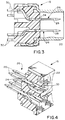
- cover 62 has a surface which defines a plurality of parallel conductor support channels, generally designated 72.
- Each channel defines an upper conductor support level 74 and a lower conductor support level 76 which are arranged such that a lower conductor support level of one channel is between two upper conductor support levels of adjacent channels. This commonly is called a "hill and dale" configuration.
- Transverse insulation displacement termination slots 78 are provided in each upper conductor support level 74 for receiving U-shaped insulation displacement portions 30 of terminals 26.
- Other slots 80 are shown in Figures 5 and 6 in the lower conductor support levels 76, but these slots simply are provided as "core-out" access areas to facilitate molding cover 62 integrally of plastic material.
- the invention contemplates a unique system wherein conductor hold down means are operatively associated with each conductor support channel 72 to hold a respective conductor of ribbon cable 12 down into the channel.
- projections 82 are molded integrally with cover 62 and protrude into each channel above the lower conductor support level 76 thereof.
- the projections are provided on opposite sides of each channel and, as best seen in Figure 7, are spaced apart less than the diameter of a conductor "C". Therefore, the conductors can be pressed into conductor support channels 72 in the direction of arrows "D" (Fig. 7) past projections 82 in a type of snap-action.
- the conductors will be held below upper conductor support levels 74 and above lower conductor support levels 76, as seen clearly in Figure 7.
- An advantage of providing conductor hold down means in the form of projections 82 concerns the inability of providing precision and consistency with plastic components over time.
- prior art "hill and dale” systems employ mirror imaged housing components to embrace and sandwich the ribbon cable therebetween.
- the conductors of the ribbon cable are forced in their respective conductor support channels between the mirror imaged housing components. While such a structure can operate effectively, it inherently presents some problems due to the cable being aligned between two plastic "hill and dale” members, each of which may vary in size slightly because of changes in molding conditions, lot to lot variability in the plastic material, differences in mold tooling as well as wear of the mold.
- precision tooling is used to "assemble" the ribbon cable to cover 62 prior to assembling the cover to housing 15 and terminating the conductors to terminals 26.
- Tool 90 is in the form of a hand, pneumatic or hydraulic press having a piston or ram 92 mounted in a support arm 94 for reciprocation in the direction of double-headed arrow "E".
- a two-position slide 96 is mounted on the lower distal end of piston 92 for adjustment in the direction of double-headed arrow "F".
- Arm 94 projects upwardly from a base 98 which has a pair of upwardly projecting spring loaded cable retainers 100 above a pair of base plates 102.
- a cavity 104 is formed in base 98 between base plates 102.
- the cavity is of a size/configuration for nesting a single cover 62 therewithin.
- An alignment pin 106 may be provided in cavity 104 for insertion into an alignment hole (not shown) in the cover to precisely align the cover for a precision operation.
- the cover will be generally flush with the tops of base plates 102.
- a ribbon cable 12 is shown in phantom on base plates 102 and spanning cavity 104 within which a cover is positionable.
- Grooves 108 may be formed in the upwardly facing surface of base plates 102 and running parallel to the length of the ribbon cable. The grooves have a profile corresponding to the undulated profile of the ribbon cable. Again, these grooves can be machined with considerable precision, since base 98, base plates 102, pin 106, cable retainers 100, etc. all can be fabricated precisely of metal material with a precision which simply cannot be accomplished in molded plastic.
- Slide 96 has two press plates 110 and 112 on the underside thereof.
- Press plate 110 has a "hill and dale" profile which is a mirror image of the channelled profile of cover 62. It is precisely machined of metal material and is effective to drive the individual conductors of the ribbon cable into the channels of the cover as the individual insulated conductors are cut and separated from each other. That is, as the press plate forces the individual conductors towards cover 62, the press plate and cover cut and separate the individual conductors.
- Press plate 112 comprises a connector housing retainer and aligner for mounting one of the housings 15.
- a ribbon cable 12 is positioned across the base of the tool as seen in Figure 8, spanning a cover 62 positioned within cavity 104.
- Cable retainers 100 are pivoted in the direction of arrows "G" to hold the cable in position.
- the cable retainers are spring loaded to a hold down position.
- the tool then is actuated to drive piston 92, slide 96 and press plate 110 downwardly into engagement with the cable to cause the press plate 110 and the "hill and dale" profile of cover 62 to interact to cut and separate the individual conductors of the cable and drive the conductors into the conductor support channels 72 of the cover positioned within cavity 104 of the tool.
- certain insulation materials will have a tendency to stretch rather than be cut.
- Press plate 110 is effective to separate or isolate the individual insulated conductors as they are driven into the conductor support channels.
- Hold down projections 82 of the cover hold the individual conductors in their support channels and prevent the conductors from coming out the channels which could result in misalignment of the conductors and shorting between the conductors upon assembly to housing 15 and termination with terminals 26.
- hold down projections 82 act as the sole means for retaining each conductor within the conductor support channel prior to termination of the connector to the ribbon cable to terminate the connector with the ribbon cable.
- such projections 82 could be eliminated and the support channels dimensioned to securely hold the separated conductors within the channels.
- Slide 96 then is adjusted to bring a connector housing 15 (which is retained and aligned by press plate 112) into alignment with cavity 104 and the "assembled" cover and cable thereat.
- the tool again is actuated to drive piston 92, slide 96, press plate 112 and the housing 15 downwardly into assembly with the cover and cable.
Abstract
Description
- This invention generally relates to the art of electrical connectors and, particularly, to an electrical connector assembly for terminating a multi-conductor flat cable such as a ribbon cable.
- Electrical connectors have been provided in a wide variety of configurations for terminating multi-conductor cables such as integral flat or ribbon cables. With the ever-increasing miniaturization of electrical connectors and the ever-increasing numbers of wires in multi-conductor cables, electrical connectors of the character described have become increasingly complicated in order to accommodate relatively large numbers of conductors terminated in relatively small connectors. For instance, a ribbon cable may have conductors on close centerline spacing on the order of .025 inches. Connectors for such high density ribbon cables are used in a variety of applications, such as connecting disk drives in computers.
- Most electrical connectors for terminating ribbon cables are of the insulation displacing termination type. These connectors generally include a housing having a mating face, an opposed cable-receiving face, and at least two rows of terminal-receiving passages extending between the faces. A plurality of terminals, most often stamped and formed of sheet metal material, are received in respective passages, each terminal having a mating portion toward the mating face of the housing and a generally U-shaped insulation displacement portion toward the cable-receiving face of the housing. Some form of secondary housing component, such as a cover, is provided for forcing conductors of the ribbon cable into the U-shaped insulation displacement portions of the terminals, with the cover embracing the ribbon cable between the cover and the cable-receiving face of the housing.
- One of the problems with connectors of the character described immediately above, centers around the high density of the conductors in the ribbon cable. Because of the close spacing of the conductors, the insulation displacement portions of the terminals are arranged in two generally spaced-apart staggered rows with adjacent terminals located in opposite rows. Therefore, a conductor to be terminated in an insulation displacement portion located in a back row will necessarily have to pass between two insulation displacement portions located in a front row. The close spacing of the conductors and terminals may create problems and may result in shorting. One solution to this particular problem is to utilize the so-called "hill and dale" system which locates portions of adjacent conductors at the insulation displacement sections of adjacent terminals in different vertical positions or levels. However, molding the connector components for effecting this approach may be rather complicated and expensive.
- More particularly, in a "hill and dale" system or connector, the cover has a cable-embracing face with a profile defined by a plurality of parallel conductor support channels. Each channel defines upper and lower conductor support levels arranged such that a lower conductor support level of one channel is between two upper conductor support levels of adjacent channels. The cable-receiving face of the connector housing has a similar multi-level channel configuration which is a mirror image of the configuration or profile of the cable-embracing face of the cover. Therefore, the channelled faces of the cover and the housing sort of "mesh" during termination of the conductors of the ribbon cable. Of course, it can be understood that major modifications may be required to the connector housing in order to provide the channelled cable-receiving face complementary to the channelled cable-embracing face of the cover. It would be desirable to provide a similar system wherein the main connector housing does not have to be modified, and modifications only need be made to the cover or secondary housing component. This invention is directed to that end.
- Still further, "hill and dale" systems as well as other insulation displacement systems of the prior art, namely those systems which incorporate a mirror imaged cable-receiving face on the connector housing complementary to the cable-embracing face on the cover, have not proven to be precise and consistent in their terminations. This is due to the inability over time to mold plastic components with sufficient precision and consistency to accommodate such closely spaced terminals. According to another aspect of the invention, tooling can be used to force the conductors of the ribbon cable into the conductor support channels of the secondary housing component or cover and held thereinto by a novel conductor hold down means.
- An object, therefore, of the invention is to provide a new and improved insulation displacement connector assembly for high density ribbon cable.
- In the exemplary embodiment of the invention, an electrical connector is disclosed for insulation displacing termination of ribbon cable having insulated conductors on predetermined close centerline spacing. The connector includes a housing having a mating face, an opposed cable-receiving face and a plurality of terminal-receiving passages extending between the faces. A plurality of terminals are received in the passages. Each terminal includes a mating portion toward the mating face of the housing and a slotted U-shaped insulation displacement portion toward the cable-receiving face of the housing. The insulation displacement portions of the terminals are arranged staggered in at least two rows. A dielectric cover is provided for forcing the conductors into the U-shaped insulation displacement portions and embracing the cable between the cover and the cable-receiving face of the housing. The cover includes surface means for engaging the cable and recess means in the surface means for receiving the U-shaped insulation displacement portions of the terminals.
- The invention contemplates that the surface means of the cover define a plurality of parallel conductor support channels. Each channel defines upper and lower conductor support levels arranged such that a lower conductor support level of one channel is between two upper conductor support levels of adjacent channels. Conductor hold down means are operatively associated with each channel to hold a respective conductor therein. Therefore, the ribbon cable can be pressed into the conductor support channels of the cover and held on the cover for subsequent termination of the cable to the terminals on the connector housing.
- In the preferred embodiment of the invention, the recess means are provided by transverse slots in the upper conductor support levels. The conductor support channels are spaced on the order of 25 mils to accommodate a 25 mil conductor centerline spacing of the ribbon cable. The cover is molded of dielectric material such as plastic, and the conductor hold down means are provided by integral projections which protrude into each conductor support channel above the lower conductor support level thereof.
- The invention also contemplates the provision of a ribbon cable in which the insulation thereof is cut between the conductors in an area embraced by the cover at the conductor support channels. Therefore, precise tooling can be used to cut or slit the ribbon cable and then to press the separated conductors into the conductor support channels of the cover.
- Other objects, features and advantages of the invention will be apparent from the following detailed description taken in connection with the accompanying drawings.
- The features of this invention which are believed to be novel are set forth with particularity in the appended claims. The invention, together with its objects and the advantages thereof, may be best understood by reference to the following description taken in conjunction with the accompanying drawings, in which like reference numerals identify like elements in the figures and in which:
- FIGURE 1 is an exploded perspective view of an electrical connector assembly of the prior art, for insulation displacement termination of a ribbon cable;
- FIGURE 2 is an exploded perspective view of the connector assembly of the invention;
- FIGURE 3 is a vertical section, on an enlarged scale, through the housing and taken generally along line 3-3 of Figure 2;
- FIGURE 4 is a fragmented perspective view of a portion of the housing and terminals of Figure 3;
- FIGURE 5 is a fragmented perspective view, on an enlarged scale, of the cable-embracing face of the cover;
- FIGURE 6 is a vertical section, on an enlarged scale, through the cover and taken generally along line 6-6 of Figure 2;
- FIGURE 7 is a horizontal section, on an enlarged scale, through the cover and taken generally along line 7-7 of Figure 2; and
- FIGURE 8 is a perspective view of a tool for use in assembling the ribbon cable to the cover.
- Referring to the drawings in greater detail, and first to Figure 1, an electrical connector assembly of the prior art, generally designated 10, is shown for insulation displacing termination of a ribbon cable, generally designated 12. The ribbon cable is of a conventional configuration and has a plurality of
conductors 14 on predetermined close centerline spacing. The conductors are surrounded by insulation which also integrally joins adjacent conductors, as is well known in the art. Therefore,opposite faces 16 of the integral flat ribbon cable are undulated transversely of the cable. -
Prior art connector 10 includes a housing, generally designated 15, a cover, generally designated 17, and a strain relief member, generally designated 18. All of these three connector components are elongated transversely ofribbon cable 12 as is shown in the drawings.Housing 15 includes amating face 20, an opposed cable-receivingface 22 and a plurality of terminal-receivingpassages 24 extending between the faces. A plurality of terminals, generally designated 26, are received inpassages 24. Each terminal includes a mating portion or pin 28 towardmating face 20 ofhousing 15 and a slotted U-shapedinsulation displacement portion 30 toward cable-receivingface 22. As will be more clearly described below,insulation displacement portions 30 are arranged staggered in two pairs of two rows longitudinally ofhousing 15 andconnector assembly 10. -
Cover 17 is unitarily molded of dielectric material, such as plastic or the like, and includes an elongated, generallyflat body portion 32 havingresilient latch arms 34 at opposite ends thereof. The latch arms haveopenings 36 which snap overlatch bosses 38 at opposite ends ofhousing 15. Generally, cover 17 operates to forceconductors 14 ofribbon cable 12 into the U-shapedinsulation displacement portions 30 ofterminals 26 and embrace the cable between the cover and cable-receivingface 22 of the housing. More particularly, the cover includes an innerflat surface 40 for engaging the cable. A plurality oftroughs 42 along opposite edges ofsurface 40 and a plurality of troughs 44 along the center ofsurface 40 are provided for registering with the conductors of the ribbon cable. In essence, the troughs match the undulatedsides 16 of the ribbon cable. - It can be seen in Figure 1 that the bottoms of
troughs 42 and 44 are flush with or form continuations offlat surface 40 of the cover. Two pairs of two rows ofholes 46 are provided inflat surface 40 of the cover for receiving the U-shapedinsulation displacement portions 30 ofterminals 26. The holes may extend completely throughbody portion 32 of the cover, but, conventionally, the holes are just deep enough to accommodate the insulation displacement portions of the terminals as the insulation displacement portions pierce through the ribbon cable. It can be seen that the holes in each pair of two rows are arranged staggered in each pair of rows. Ifconductors 14 are on 25 mil centerline spacing, the holes in the two rows of each pair are spaced on the order of 50 mils. In operation, ascover 17 is used to forceconductors 14 ofribbon cable 12 intoinsulation displacement portions 30 ofterminals 26. The undulated surface of the ribbon cable seats intotroughs 42 and 44 which, thereby, aligns or registers the conductors withholes 46 and the insulation displacement portions of the terminals. With the cable embraced betweensurface 40 of the cover and cable-receivingface 22 of the housing, forcing the cover into a fully latched position on the housing effects insulation displacement termination of all of the terminals with all of the conductors of the ribbon cable. -
Strain relief member 18 also is a unitarily molded component of dielectric material, such as plastic or the like, and has a pair oflatch arms 48 at opposite ends thereof, with the latch arms having inwardly directedhook portions 48a. The hook portions snappingly engage overshoulders 50 at opposite ends ofcover 17. The strain relief member has an elongatedbody portion 52 provided with alongitudinally extending slot 54 completely through the cover. In assembly,ribbon cable 12 is inserted throughslot 54 in the direction of arrow "A", and the cable then is wrapped around one edge ofbody portion 32 ofcover 17 so that a trimmed end of the cable can be positioned againstsurface 40 of the cover. Therefore, the cable is assembled in a sort of serpentine configuration throughslot 54 instrain relief member 18 and aboutbody portion 32 ofcover 17, whereupon the strain relief member clamps the cable against aback side 56 of the cover when the strain relief member is clampingly latched to the cover. - Figure 2 shows an electrical connector, generally designated 60, embodying the concepts of the invention.
Ribbon cable 12,housing 15 andstrain relief member 18 ofconnector 60 are identical to those components of priorart connector assembly 10 described above and shown in Figure 1. Therefore, the details of the ribbon cable, housing and strain relief member will not be repeated, and like reference numerals have been applied in Figure 2 corresponding to like items described in relation to Figure 1. However, Figures 3 and 4 shows a section throughhousing 15 to illustrate the configuration of and relationship betweenterminals 26, and to show the flat nature of cable-receivingface 22 of the housing. Figures 3 and 4 also shows that the housing has a dielectric body 15a and a conventional conductive shield 15b. As pointed out in the "Background,"housing 15 of the prior art remains substantially unchanged and no major modifications need be made thereto. Only the cover of the connector is changed, as described immediately below. - More particularly,
connector 60 of the invention includes a cover, generally designated 62, having anelongated body 64 withflexible latch arms 66 at opposite ends thereof. The latch arms defineopenings 68 for latchingly engaginglatch bosses 38 ofhousing 15.Hook portions 48a oflatch arms 48 ofstrain relief member 18 latchingly engage shoulders or surfaces 70 at opposite ends of the cover. - Referring to Figures 5 and 6 in conjunction with Figure 2, cover 62 has a surface which defines a plurality of parallel conductor support channels, generally designated 72. Each channel defines an upper
conductor support level 74 and a lowerconductor support level 76 which are arranged such that a lower conductor support level of one channel is between two upper conductor support levels of adjacent channels. This commonly is called a "hill and dale" configuration. Transverse insulationdisplacement termination slots 78 are provided in each upperconductor support level 74 for receiving U-shapedinsulation displacement portions 30 ofterminals 26.Other slots 80 are shown in Figures 5 and 6 in the lowerconductor support levels 76, but these slots simply are provided as "core-out" access areas to facilitatemolding cover 62 integrally of plastic material. - The invention contemplates a unique system wherein conductor hold down means are operatively associated with each
conductor support channel 72 to hold a respective conductor ofribbon cable 12 down into the channel. Specifically,projections 82 are molded integrally withcover 62 and protrude into each channel above the lowerconductor support level 76 thereof. The projections are provided on opposite sides of each channel and, as best seen in Figure 7, are spaced apart less than the diameter of a conductor "C". Therefore, the conductors can be pressed intoconductor support channels 72 in the direction of arrows "D" (Fig. 7)past projections 82 in a type of snap-action. The conductors will be held below upperconductor support levels 74 and above lowerconductor support levels 76, as seen clearly in Figure 7. - An advantage of providing conductor hold down means in the form of
projections 82 concerns the inability of providing precision and consistency with plastic components over time. In particular, as pointed out in the "Background," above, prior art "hill and dale" systems employ mirror imaged housing components to embrace and sandwich the ribbon cable therebetween. The conductors of the ribbon cable are forced in their respective conductor support channels between the mirror imaged housing components. While such a structure can operate effectively, it inherently presents some problems due to the cable being aligned between two plastic "hill and dale" members, each of which may vary in size slightly because of changes in molding conditions, lot to lot variability in the plastic material, differences in mold tooling as well as wear of the mold. With the connector system of the invention, precision tooling is used to "assemble" the ribbon cable to cover 62 prior to assembling the cover tohousing 15 and terminating the conductors toterminals 26. - More particularly, reference is made to Figure 8 wherein a tool, generally designated 90, is somewhat schematically illustrated, it being understood that other types of tools can be designed.
Tool 90 is in the form of a hand, pneumatic or hydraulic press having a piston or ram 92 mounted in asupport arm 94 for reciprocation in the direction of double-headed arrow "E". A two-position slide 96 is mounted on the lower distal end ofpiston 92 for adjustment in the direction of double-headed arrow "F".Arm 94 projects upwardly from a base 98 which has a pair of upwardly projecting spring loadedcable retainers 100 above a pair ofbase plates 102. Acavity 104 is formed inbase 98 betweenbase plates 102. The cavity is of a size/configuration for nesting asingle cover 62 therewithin. Analignment pin 106 may be provided incavity 104 for insertion into an alignment hole (not shown) in the cover to precisely align the cover for a precision operation. The cover will be generally flush with the tops ofbase plates 102. Aribbon cable 12 is shown in phantom onbase plates 102 and spanningcavity 104 within which a cover is positionable.Grooves 108 may be formed in the upwardly facing surface ofbase plates 102 and running parallel to the length of the ribbon cable. The grooves have a profile corresponding to the undulated profile of the ribbon cable. Again, these grooves can be machined with considerable precision, sincebase 98,base plates 102,pin 106,cable retainers 100, etc. all can be fabricated precisely of metal material with a precision which simply cannot be accomplished in molded plastic. -
Slide 96 has twopress plates Press plate 110 has a "hill and dale" profile which is a mirror image of the channelled profile ofcover 62. It is precisely machined of metal material and is effective to drive the individual conductors of the ribbon cable into the channels of the cover as the individual insulated conductors are cut and separated from each other. That is, as the press plate forces the individual conductors towardscover 62, the press plate and cover cut and separate the individual conductors.Press plate 112 comprises a connector housing retainer and aligner for mounting one of thehousings 15. - In operation of
tool 90, aribbon cable 12 is positioned across the base of the tool as seen in Figure 8, spanning acover 62 positioned withincavity 104.Cable retainers 100 are pivoted in the direction of arrows "G" to hold the cable in position. The cable retainers are spring loaded to a hold down position. The tool then is actuated to drivepiston 92, slide 96 andpress plate 110 downwardly into engagement with the cable to cause thepress plate 110 and the "hill and dale" profile ofcover 62 to interact to cut and separate the individual conductors of the cable and drive the conductors into theconductor support channels 72 of the cover positioned withincavity 104 of the tool. It should be noted that certain insulation materials will have a tendency to stretch rather than be cut. However, in such a case, the conductors would still be separated.Press plate 110 is effective to separate or isolate the individual insulated conductors as they are driven into the conductor support channels. Hold downprojections 82 of the cover hold the individual conductors in their support channels and prevent the conductors from coming out the channels which could result in misalignment of the conductors and shorting between the conductors upon assembly tohousing 15 and termination withterminals 26. As such, hold downprojections 82 act as the sole means for retaining each conductor within the conductor support channel prior to termination of the connector to the ribbon cable to terminate the connector with the ribbon cable. In the alternative,such projections 82 could be eliminated and the support channels dimensioned to securely hold the separated conductors within the channels. -
Slide 96 then is adjusted to bring a connector housing 15 (which is retained and aligned by press plate 112) into alignment withcavity 104 and the "assembled" cover and cable thereat. The tool again is actuated to drivepiston 92,slide 96,press plate 112 and thehousing 15 downwardly into assembly with the cover and cable. - By utilizing the
press plate 112 to force the ribbon cable intocover 62, precise positioning of the cable may be maintained. In addition, the shearing edges of the "hill and dale" profile may also easily be maintained in their desired sharp condition. Further, the positioning of thecover 62,cable 12 andhousing 15 relative to each other may also be maintained better due to a reduction in the number of components (particularly plastic components) fitting together to effect the termination. - It will be understood that the invention may be embodied in other specific forms without departing from the spirit or central characteristics thereof. The present examples and embodiments, therefore, are to be considered in all respects as illustrative and not restrictive, and the invention is not to be limited to the details given herein.
Claims (11)
- In an electrical connector (60) for insulation displacing termination of ribbon cable (12) having insulated conductors (14) on predetermined close centerline spacing, including a dielectric housing (15) having a mating face (20), an opposed cable-receiving face (22) and a plurality of terminal-receiving passages (24) extending between the faces, a plurality of terminals (26) received in the passages, each terminal including a mating portion (28) toward said mating face and a slotted U-shaped insulation displacement portion (30) toward the cable-receiving face, the insulation displacement portions of the terminals being arranged staggered in at least two rows, and a dielectric cover (62) for forcing the conductors into the U-shaped insulation displacement portions and embracing the cable between the cover and the cable-receiving face of the housing, the cover including surface means (72) for engaging the cable and recess means (78) in the surface means for receiving the U-shaped insulation displacement portions of the terminals,
characterized by:
said surface means of the cover define a plurality of parallel conductor support channels (72), each of the channels defining upper (74) and lower (76) conductor support levels arranged such that a lower conductor support level (76) of one channel (72) is between two upper conductor support levels (74) of adjacent channels, and
conductor hold down means (82) operatively associated with each channel to hold a respective conductor therein,
whereby the ribbon cable (12) can be pressed into the conductor support channels (72) of the cover (62) and held on the cover for subsequent termination of the cable to the terminals (26) on the connector housing (15). - In an electrical connector as set forth in claim 1, wherein said recess means comprise transverse slots (78) in the upper conductor levels.
- In an electrical connector as set forth in claim 1, wherein said conductor support channels (72) are spaced on the order of 25 mils to accommodate a 25 mil centerline spacing of the ribbon cable (12).
- In an electrical connector as set forth in claim 1, wherein said cover (62) is molded of dielectric material such as plastic, and said conductor hold down means comprise integral projections (82) which protrude into each conductor support channel (72) above the lower conductor support level (76) thereof.
- In combination with the electrical connector of claim 1, a ribbon cable (12) in which the insulation thereof is cut between the conductors (14) in an area embraced by the cover (62) at the conductor support channels (72).
- In an electrical connector as set forth in claim 1, wherein said conductor hold down means is adapted to be the sole means for retaining each conductor of said ribbon cable in said conductor support channels prior to termination of the cable to the terminals on the connector housing.
- In an electrical connector as set forth in claim 4, wherein said conductor integral projections are adapted to be the sole means for retaining each conductor of said ribbon cable in said conductor support channels prior to termination of the cable to the terminals on the connector housing.
- A method of terminating an electrical connector (60) for insulation displacing termination of ribbon cable (12) having insulated conductors (14) on predetermined close centerline spacing, the connector including a dielectric housing (15) having a mating face (20), an opposed cable-receiving face (22) and a plurality of terminal-receiving passages (24) extending between the faces, a plurality of terminals (26) received in the passages, each terminal including a mating portion (28) toward said mating face and a slotted U-shaped insulation displacement portion (30) toward the cable-receiving face, the insulation displacement portions of the terminals being arranged staggered in at least two rows, and a dielectric cover (62) for forcing the conductors into the U-shaped insulation displacement portions and embracing the cable between the cover and the cable-receiving face of the housing, the cover including surface means for engaging the cable and recess means (78) in the surface means for receiving the U-shaped insulation displacement portions of the terminals, said surface means having a plurality of parallel conductor support channels (72), each of the channels defining upper and lower conductor support levels (74, 76) arranged such that a lower conductor support level of one channel is between two upper conductor support levels of adjacent channels comprising the steps of:
providing a press tool (90) having a reciprocally movable press plate (110), said press plate having a cable engaging surface with a plurality of parallel conductor support channels, each of the channels defining upper and lower conductor support levels arranged such that a lower conductor support level is positioned between two upper conductor support levels of adjacent channels;
positioning said cover in a cover nest (104) of said press tool with said surface means facing in a first direction, said cover being oriented such that the upper conductor support levels of said press tool are aligned with the lower conductor support levels of said cover and the lower conductor support levels of said press tool are aligned with the upper conductor support levels of said cover;
positioning said ribbon cable (12) having insulated conductors adjacent said cover and said cover nest;
engaging one side of said ribbon cable with said press plate to press the ribbon cable in a direction opposite said first direction and against said cover in order to separate a portion of said conductors of said ribbon cable and press said separated conductors into said conductor support channels of the cover to create a cover and cable subassembly; and
moving said housing relative to said cover and cable subassembly to force said U-shaped insulation displacement portions of the terminals into engagement with said conductors to terminate said electrical connector to said cable. - The method of claim 8, wherein said press tool includes a housing nest (112) for retaining said housing prior to termination of said cable to said U-shaped insulation displacement portions of the terminals, and said housing nest and housing is aligned with said cover and cable subassembly prior to said moving step.
- The method of claim 8 wherein said cover includes conductor hold down means (82) operatively associated with each channel to hold a respective conductor therein.
- The method of claim 10 wherein said conductor hold down means comprise integral projections (82) that protrude into each conductor support channel, and said integral projections are the sole means for retaining each conductor of said ribbon cable within its respective conductor support channel prior to said moving step.
Applications Claiming Priority (2)
| Application Number | Priority Date | Filing Date | Title |
|---|---|---|---|
| US08/105,224 US5358424A (en) | 1993-08-11 | 1993-08-11 | Electrical connector for high density ribbon cable |
| US105224 | 1993-08-11 |
Publications (3)
| Publication Number | Publication Date |
|---|---|
| EP0638958A2 true EP0638958A2 (en) | 1995-02-15 |
| EP0638958A3 EP0638958A3 (en) | 1997-05-02 |
| EP0638958B1 EP0638958B1 (en) | 1999-02-24 |
Family
ID=22304682
Family Applications (1)
| Application Number | Title | Priority Date | Filing Date |
|---|---|---|---|
| EP94112319A Expired - Lifetime EP0638958B1 (en) | 1993-08-11 | 1994-08-06 | Electrical connector for high density ribbon cable |
Country Status (5)
| Country | Link |
|---|---|
| US (1) | US5358424A (en) |
| EP (1) | EP0638958B1 (en) |
| JP (1) | JP3019188U (en) |
| DE (1) | DE69416625T2 (en) |
| SG (1) | SG44542A1 (en) |
Families Citing this family (20)
| Publication number | Priority date | Publication date | Assignee | Title |
|---|---|---|---|---|
| JP2942979B2 (en) * | 1994-11-21 | 1999-08-30 | モレックス インコーポレーテッド | Electrical connector |
| US5554047A (en) * | 1995-02-28 | 1996-09-10 | The Whitaker Corporation | Electrical connector with terminal supporting walls |
| WO1997036351A1 (en) * | 1996-03-28 | 1997-10-02 | The Whitaker Corporation | High density electrical connector |
| US5766033A (en) * | 1996-03-28 | 1998-06-16 | The Whitaker Corporation | High density electrical connector |
| US6000951A (en) * | 1997-03-18 | 1999-12-14 | Prince Corporation | Electrical ribbon wire connectors |
| US5928028A (en) * | 1997-03-26 | 1999-07-27 | Quantum Corporation | Interspersed ground ribbon cable assemblies and methods therefor |
| US6083039A (en) * | 1998-06-01 | 2000-07-04 | Itt Manufacturing Enterprises, Inc. | Connector contact mold-positioning |
| US6068504A (en) * | 1998-09-08 | 2000-05-30 | Molex Incorporated | Selective termination connector assembly |
| DE10012885C2 (en) * | 2000-03-16 | 2002-04-25 | Siemens Ag | Press-in tool for connecting a connector with a ribbon cable |
| US6704992B2 (en) * | 2001-12-21 | 2004-03-16 | Hubbell Incorporated | Cable punch assembly |
| DE10319728A1 (en) * | 2003-04-30 | 2004-11-18 | Wago Verwaltungsgesellschaft Mbh | Branch-off plug connector for contacting line cores of through lines held fixed in line holder in strip cable manner, with tap zones in line holder located in single tapping plane |
| JP2004342414A (en) * | 2003-05-14 | 2004-12-02 | Sumitomo Wiring Syst Ltd | Connector |
| US7481841B2 (en) * | 2004-06-30 | 2009-01-27 | Depuy Products, Inc. | Adjustable orthopaedic prosthesis and associated method |
| US20070082539A1 (en) * | 2005-10-12 | 2007-04-12 | Slobadan Pavlovic | Insulation displacement connection for securing an insulated conductor |
| US7134903B1 (en) | 2005-10-12 | 2006-11-14 | Lear Corporation | Insulation displacement connection |
| US7059889B1 (en) | 2005-10-12 | 2006-06-13 | Lear Corporation | Splice block for interconnecting electrical conductors |
| CN201252201Y (en) * | 2008-06-11 | 2009-06-03 | 富士康(昆山)电脑接插件有限公司 | Cable connector component |
| US10978838B2 (en) * | 2018-04-02 | 2021-04-13 | Optical Cable Corporation | Multi-stage termination of a cable to an RJ-45 outlet |
| US10186789B1 (en) | 2018-04-13 | 2019-01-22 | Rustcraft Industries LLC | Keyed cable and connector system |
| JP7051248B2 (en) * | 2019-10-16 | 2022-04-11 | 矢崎総業株式会社 | connector |
Citations (5)
| Publication number | Priority date | Publication date | Assignee | Title |
|---|---|---|---|---|
| US3432906A (en) * | 1966-10-28 | 1969-03-18 | Western Electric Co | Fixture for securing an electrical contact with a support shell |
| US4091531A (en) * | 1976-05-05 | 1978-05-30 | Amp Incorporated | Tool for simultaneously staking a plurality of wires into an electrical connector |
| GB2026256A (en) * | 1978-07-19 | 1980-01-30 | Yamaichi Electric Mfg | Electric contact terminal members |
| US4913660A (en) * | 1987-10-01 | 1990-04-03 | Honda Tsushin Kogyo Kabushiki Kaisha | Pressure-contact type connector for flat cable |
| US4948381A (en) * | 1987-12-25 | 1990-08-14 | Daiichi Denshi Kogyo Kabushiki Kaisha | Insulation-piercing connector |
Family Cites Families (8)
| Publication number | Priority date | Publication date | Assignee | Title |
|---|---|---|---|---|
| US4009922A (en) * | 1975-11-10 | 1977-03-01 | Minnesota Mining And Manufacturing Company | Connector |
| US4026625A (en) * | 1975-11-10 | 1977-05-31 | Minnesota Mining And Manufacturing Company | Universal connector |
| US4441779A (en) * | 1980-12-31 | 1984-04-10 | E. I. Du Pont De Nemours & Company | Contact device for a multiconductor cable |
| US4857010A (en) * | 1983-04-21 | 1989-08-15 | Molex Incorporated | Ribbon cable harness and method of making same |
| US4601530A (en) * | 1984-08-30 | 1986-07-22 | Amp Incorporated | Electrical connector and wire assembly method |
| US4978314A (en) * | 1988-11-24 | 1990-12-18 | Yazaki Corporation | Waterproof press-connecting connector |
| JPH0740300Y2 (en) * | 1989-05-19 | 1995-09-13 | 日本エー・エム・ピー株式会社 | Insulation displacement connector |
| JP2662531B2 (en) * | 1990-03-29 | 1997-10-15 | 第一電子工業株式会社 | IDC type connector |
-
1993
- 1993-08-11 US US08/105,224 patent/US5358424A/en not_active Expired - Fee Related
-
1994
- 1994-08-06 SG SG1996001929A patent/SG44542A1/en unknown
- 1994-08-06 DE DE69416625T patent/DE69416625T2/en not_active Expired - Fee Related
- 1994-08-06 EP EP94112319A patent/EP0638958B1/en not_active Expired - Lifetime
- 1994-08-10 JP JP1994010938U patent/JP3019188U/en not_active Expired - Lifetime
Patent Citations (5)
| Publication number | Priority date | Publication date | Assignee | Title |
|---|---|---|---|---|
| US3432906A (en) * | 1966-10-28 | 1969-03-18 | Western Electric Co | Fixture for securing an electrical contact with a support shell |
| US4091531A (en) * | 1976-05-05 | 1978-05-30 | Amp Incorporated | Tool for simultaneously staking a plurality of wires into an electrical connector |
| GB2026256A (en) * | 1978-07-19 | 1980-01-30 | Yamaichi Electric Mfg | Electric contact terminal members |
| US4913660A (en) * | 1987-10-01 | 1990-04-03 | Honda Tsushin Kogyo Kabushiki Kaisha | Pressure-contact type connector for flat cable |
| US4948381A (en) * | 1987-12-25 | 1990-08-14 | Daiichi Denshi Kogyo Kabushiki Kaisha | Insulation-piercing connector |
Also Published As
| Publication number | Publication date |
|---|---|
| DE69416625T2 (en) | 1999-11-11 |
| JP3019188U (en) | 1995-12-12 |
| EP0638958B1 (en) | 1999-02-24 |
| DE69416625D1 (en) | 1999-04-01 |
| US5358424A (en) | 1994-10-25 |
| EP0638958A3 (en) | 1997-05-02 |
| SG44542A1 (en) | 1997-12-19 |
Similar Documents
| Publication | Publication Date | Title |
|---|---|---|
| US5358424A (en) | Electrical connector for high density ribbon cable | |
| US5338221A (en) | Electrical connector for high density ribbon cable | |
| US4193654A (en) | Electrical connector receptacles | |
| US4277124A (en) | Connector having wire-in-slot connecting means and crimped strain relief | |
| US5207587A (en) | Electrical distribution center | |
| EP0630071B1 (en) | Sheet metal wire connecting device | |
| EP0390450A1 (en) | Back-to-back stackable connector for interface bus | |
| US5761805A (en) | Method of making a high density electrical connector | |
| EP0009337A1 (en) | Method of terminating flat multi-conductor electrical cable and connector therefor | |
| US4742746A (en) | Reworking and sizing of flat conductor cable | |
| US5326286A (en) | Electrical connector assembly with terminal alignment system | |
| EP0817313B1 (en) | Electrical insulation displacement connector assembly with cable clamping means | |
| US6368148B1 (en) | Ribbon cable connector with ground bus | |
| US5302137A (en) | Insulation displacement connector terminal block | |
| US4508410A (en) | Electrical termination system and connector member | |
| US4545635A (en) | Matrix connector | |
| US5711067A (en) | Method of forming electrical connector | |
| US4160574A (en) | Connector for flat wire cables having improved contacts and integral strain relief means | |
| US4315663A (en) | Multiple position brush connector | |
| US5114362A (en) | High density electrical connector and method of making a high density electrical connector | |
| EP0057780A1 (en) | Electrical connector with a terminal having a slotted wire receiving portion and wire strain relief means | |
| EP0249330A2 (en) | Insulation displacement terminal and connector | |
| CA1298371C (en) | Overmolded electrical contact for the manufacture of connectors | |
| EP0890203B1 (en) | High density electrical connector | |
| EP0228723A2 (en) | Modular IDC terminal block assembly |
Legal Events
| Date | Code | Title | Description |
|---|---|---|---|
| PUAI | Public reference made under article 153(3) epc to a published international application that has entered the european phase |
Free format text: ORIGINAL CODE: 0009012 |
|
| AK | Designated contracting states |
Kind code of ref document: A2 Designated state(s): DE FR GB IT |
|
| PUAL | Search report despatched |
Free format text: ORIGINAL CODE: 0009013 |
|
| AK | Designated contracting states |
Kind code of ref document: A3 Designated state(s): DE FR GB IT |
|
| 17P | Request for examination filed |
Effective date: 19971008 |
|
| GRAG | Despatch of communication of intention to grant |
Free format text: ORIGINAL CODE: EPIDOS AGRA |
|
| 17Q | First examination report despatched |
Effective date: 19980514 |
|
| GRAG | Despatch of communication of intention to grant |
Free format text: ORIGINAL CODE: EPIDOS AGRA |
|
| GRAH | Despatch of communication of intention to grant a patent |
Free format text: ORIGINAL CODE: EPIDOS IGRA |
|
| GRAH | Despatch of communication of intention to grant a patent |
Free format text: ORIGINAL CODE: EPIDOS IGRA |
|
| GRAA | (expected) grant |
Free format text: ORIGINAL CODE: 0009210 |
|
| AK | Designated contracting states |
Kind code of ref document: B1 Designated state(s): DE FR GB IT |
|
| ET | Fr: translation filed | ||
| REF | Corresponds to: |
Ref document number: 69416625 Country of ref document: DE Date of ref document: 19990401 |
|
| PLBE | No opposition filed within time limit |
Free format text: ORIGINAL CODE: 0009261 |
|
| STAA | Information on the status of an ep patent application or granted ep patent |
Free format text: STATUS: NO OPPOSITION FILED WITHIN TIME LIMIT |
|
| 26N | No opposition filed | ||
| REG | Reference to a national code |
Ref country code: GB Ref legal event code: IF02 |
|
| PGFP | Annual fee paid to national office [announced via postgrant information from national office to epo] |
Ref country code: GB Payment date: 20020626 Year of fee payment: 9 |
|
| PGFP | Annual fee paid to national office [announced via postgrant information from national office to epo] |
Ref country code: FR Payment date: 20020805 Year of fee payment: 9 |
|
| PGFP | Annual fee paid to national office [announced via postgrant information from national office to epo] |
Ref country code: DE Payment date: 20020830 Year of fee payment: 9 |
|
| PG25 | Lapsed in a contracting state [announced via postgrant information from national office to epo] |
Ref country code: GB Free format text: LAPSE BECAUSE OF NON-PAYMENT OF DUE FEES Effective date: 20030806 |
|
| PG25 | Lapsed in a contracting state [announced via postgrant information from national office to epo] |
Ref country code: DE Free format text: LAPSE BECAUSE OF NON-PAYMENT OF DUE FEES Effective date: 20040302 |
|
| GBPC | Gb: european patent ceased through non-payment of renewal fee |
Effective date: 20030806 |
|
| PG25 | Lapsed in a contracting state [announced via postgrant information from national office to epo] |
Ref country code: FR Free format text: LAPSE BECAUSE OF NON-PAYMENT OF DUE FEES Effective date: 20040430 |
|
| REG | Reference to a national code |
Ref country code: FR Ref legal event code: ST |
|
| PG25 | Lapsed in a contracting state [announced via postgrant information from national office to epo] |
Ref country code: IT Free format text: LAPSE BECAUSE OF NON-PAYMENT OF DUE FEES;WARNING: LAPSES OF ITALIAN PATENTS WITH EFFECTIVE DATE BEFORE 2007 MAY HAVE OCCURRED AT ANY TIME BEFORE 2007. THE CORRECT EFFECTIVE DATE MAY BE DIFFERENT FROM THE ONE RECORDED. Effective date: 20050806 |