EP0643948A1 - Process and device in respect of a three-dimensional body usable in the human body - Google Patents
Process and device in respect of a three-dimensional body usable in the human body Download PDFInfo
- Publication number
- EP0643948A1 EP0643948A1 EP94850125A EP94850125A EP0643948A1 EP 0643948 A1 EP0643948 A1 EP 0643948A1 EP 94850125 A EP94850125 A EP 94850125A EP 94850125 A EP94850125 A EP 94850125A EP 0643948 A1 EP0643948 A1 EP 0643948A1
- Authority
- EP
- European Patent Office
- Prior art keywords
- data
- tooth
- program
- alteration
- screen
- Prior art date
- Legal status (The legal status is an assumption and is not a legal conclusion. Google has not performed a legal analysis and makes no representation as to the accuracy of the status listed.)
- Granted
Links
Images

Classifications
-
- G—PHYSICS
- G05—CONTROLLING; REGULATING
- G05B—CONTROL OR REGULATING SYSTEMS IN GENERAL; FUNCTIONAL ELEMENTS OF SUCH SYSTEMS; MONITORING OR TESTING ARRANGEMENTS FOR SUCH SYSTEMS OR ELEMENTS
- G05B19/00—Programme-control systems
- G05B19/02—Programme-control systems electric
- G05B19/18—Numerical control [NC], i.e. automatically operating machines, in particular machine tools, e.g. in a manufacturing environment, so as to execute positioning, movement or co-ordinated operations by means of programme data in numerical form
- G05B19/4097—Numerical control [NC], i.e. automatically operating machines, in particular machine tools, e.g. in a manufacturing environment, so as to execute positioning, movement or co-ordinated operations by means of programme data in numerical form characterised by using design data to control NC machines, e.g. CAD/CAM
- G05B19/4099—Surface or curve machining, making 3D objects, e.g. desktop manufacturing
-
- A—HUMAN NECESSITIES
- A61—MEDICAL OR VETERINARY SCIENCE; HYGIENE
- A61C—DENTISTRY; APPARATUS OR METHODS FOR ORAL OR DENTAL HYGIENE
- A61C13/00—Dental prostheses; Making same
- A61C13/0003—Making bridge-work, inlays, implants or the like
- A61C13/0004—Computer-assisted sizing or machining of dental prostheses
-
- A—HUMAN NECESSITIES
- A61—MEDICAL OR VETERINARY SCIENCE; HYGIENE
- A61C—DENTISTRY; APPARATUS OR METHODS FOR ORAL OR DENTAL HYGIENE
- A61C9/00—Impression cups, i.e. impression trays; Impression methods
- A61C9/004—Means or methods for taking digitized impressions
- A61C9/0046—Data acquisition means or methods
- A61C9/008—Mechanical means or methods, e.g. a contact probe moving over the teeth
-
- G—PHYSICS
- G05—CONTROLLING; REGULATING
- G05B—CONTROL OR REGULATING SYSTEMS IN GENERAL; FUNCTIONAL ELEMENTS OF SUCH SYSTEMS; MONITORING OR TESTING ARRANGEMENTS FOR SUCH SYSTEMS OR ELEMENTS
- G05B19/00—Programme-control systems
- G05B19/02—Programme-control systems electric
- G05B19/42—Recording and playback systems, i.e. in which the programme is recorded from a cycle of operations, e.g. the cycle of operations being manually controlled, after which this record is played back on the same machine
- G05B19/4202—Recording and playback systems, i.e. in which the programme is recorded from a cycle of operations, e.g. the cycle of operations being manually controlled, after which this record is played back on the same machine preparation of the programme medium using a drawing, a model
- G05B19/4207—Recording and playback systems, i.e. in which the programme is recorded from a cycle of operations, e.g. the cycle of operations being manually controlled, after which this record is played back on the same machine preparation of the programme medium using a drawing, a model in which a model is traced or scanned and corresponding data recorded
-
- G—PHYSICS
- G05—CONTROLLING; REGULATING
- G05B—CONTROL OR REGULATING SYSTEMS IN GENERAL; FUNCTIONAL ELEMENTS OF SUCH SYSTEMS; MONITORING OR TESTING ARRANGEMENTS FOR SUCH SYSTEMS OR ELEMENTS
- G05B2219/00—Program-control systems
- G05B2219/30—Nc systems
- G05B2219/35—Nc in input of data, input till input file format
- G05B2219/35114—Generation of connection between two or more surfaces
-
- G—PHYSICS
- G05—CONTROLLING; REGULATING
- G05B—CONTROL OR REGULATING SYSTEMS IN GENERAL; FUNCTIONAL ELEMENTS OF SUCH SYSTEMS; MONITORING OR TESTING ARRANGEMENTS FOR SUCH SYSTEMS OR ELEMENTS
- G05B2219/00—Program-control systems
- G05B2219/30—Nc systems
- G05B2219/35—Nc in input of data, input till input file format
- G05B2219/35217—Cagd computer aided geometric design, sbgd scanning based geometric design
-
- G—PHYSICS
- G05—CONTROLLING; REGULATING
- G05B—CONTROL OR REGULATING SYSTEMS IN GENERAL; FUNCTIONAL ELEMENTS OF SUCH SYSTEMS; MONITORING OR TESTING ARRANGEMENTS FOR SUCH SYSTEMS OR ELEMENTS
- G05B2219/00—Program-control systems
- G05B2219/30—Nc systems
- G05B2219/35—Nc in input of data, input till input file format
- G05B2219/35315—Projection, two, three section views
-
- G—PHYSICS
- G05—CONTROLLING; REGULATING
- G05B—CONTROL OR REGULATING SYSTEMS IN GENERAL; FUNCTIONAL ELEMENTS OF SUCH SYSTEMS; MONITORING OR TESTING ARRANGEMENTS FOR SUCH SYSTEMS OR ELEMENTS
- G05B2219/00—Program-control systems
- G05B2219/30—Nc systems
- G05B2219/45—Nc applications
- G05B2219/45167—Dentist, dental manufacture
-
- G—PHYSICS
- G16—INFORMATION AND COMMUNICATION TECHNOLOGY [ICT] SPECIALLY ADAPTED FOR SPECIFIC APPLICATION FIELDS
- G16H—HEALTHCARE INFORMATICS, i.e. INFORMATION AND COMMUNICATION TECHNOLOGY [ICT] SPECIALLY ADAPTED FOR THE HANDLING OR PROCESSING OF MEDICAL OR HEALTHCARE DATA
- G16H20/00—ICT specially adapted for therapies or health-improving plans, e.g. for handling prescriptions, for steering therapy or for monitoring patient compliance
- G16H20/40—ICT specially adapted for therapies or health-improving plans, e.g. for handling prescriptions, for steering therapy or for monitoring patient compliance relating to mechanical, radiation or invasive therapies, e.g. surgery, laser therapy, dialysis or acupuncture
-
- Y—GENERAL TAGGING OF NEW TECHNOLOGICAL DEVELOPMENTS; GENERAL TAGGING OF CROSS-SECTIONAL TECHNOLOGIES SPANNING OVER SEVERAL SECTIONS OF THE IPC; TECHNICAL SUBJECTS COVERED BY FORMER USPC CROSS-REFERENCE ART COLLECTIONS [XRACs] AND DIGESTS
- Y10—TECHNICAL SUBJECTS COVERED BY FORMER USPC
- Y10S—TECHNICAL SUBJECTS COVERED BY FORMER USPC CROSS-REFERENCE ART COLLECTIONS [XRACs] AND DIGESTS
- Y10S623/00—Prosthesis, i.e. artificial body members, parts thereof, or aids and accessories therefor
- Y10S623/901—Method of manufacturing prosthetic device
Definitions
- the present invention relates to a process for achieving, by means of input data representing a three-dimensional body usable in the human body, output data which can be used for manufacturing purposes and represent an altered or extended variant of the body.
- input data representing a three-dimensional body usable in the human body
- output data which can be used for manufacturing purposes and represent an altered or extended variant of the body.
- a tooth sleeve, dental bridge or other dental structure can be mentioned.
- the said input data are fed to a computer installation from which the said output data can be extracted in dependence upon the input data.
- the computer installation exhibits a computer screen and operates with a CADD-program (Computer Aided Dental Design).
- the program derives from principles for CAD-programs (Computer Aided Design) and has been adapted for the said functions and fields of application.
- an alteration or extension attributable to the body variant relative to the three-dimensional body can be simulated.
- terminal members by means of which the alteration or extension in question is effected.
- the invention relates also to a device for realizing the said process.
- Swedish patent 9003967-8 (468 198)
- the known equipment proposes purely general usage of computer-aided equipment, in which particular alterations and extensions can be attached to a model, in question or to fed-in data representing a model and design measures relating to the product in question can be taken with the aid of attached input data.
- the dentist/dental technician In the case of conventional manual formulation of tooth sleeves, tooth crowns, etc., the dentist/dental technician formulated the model in question which was dispatched to the manufacturer. When the dentist/dental technician received the model back, adjustments were made to it and sent back to the manufacturer, etc., until a product offering approved results was obtained.
- Readings of three-dimensional bodies normally involve large quantities of data.
- Various measures have been proposed for keeping these data quantities down.
- the object of the present invention is to solve these problems and to propose a tool or aid for highly advanced, on-site model production or model copying.
- the invention solves this problem also by making it possible for only data relating to the shaping of the model to have to be dispatched to the manufacturer via modem, diskette, etc.
- the invention proposes the utilization of computer-aided equipment, which is normally a new instrument for currently practising dentists/dental technicians. It is therefore important that the tools or aids should be able to operate with simple handling principles and routines.
- the invention solves these problems.
- the manufacturing accuracy in products of this type must be kept high, e.g. ⁇ 10 ⁇ m, in order to be able to function well when fitted to a patient. Such accuracy can entail machine accuracies and computing accuracies of ⁇ 0.0015 mm.
- the design or formulation of tooth sleeves, dental bridges, etc. must therefore be able to be carried out with great precision and clarity.
- the output data which are produced and which will serve as a basis for milling and other machining coordinates must be accurate. The invention solves this problem.
- the invention largely solves this problem and permits routines in which repeated dealings with the product in question can be eliminated.
- the dentist/dental technician can make a clear contribution and does not need to feel his/her way along in successive stages.
- the dentist/dental technician can easily influence the shape in the copying process, as well as when checking patient-matching. He/she can optimally utilize available spaces for cement and modifications. Accurate adjustments can be made to the interface between the sleeve/bridge and tooth remnants, jawbone, etc.
- the angling of the sleeve material at the preparation line (the end edge of the shell) or preparation boundary should be made exact.
- the angling should be effected, moreover, in dependence upon the position on the tooth, i.e. a first angle should be obtained on the outer side of the tooth and a second angle on the inner side of the tooth, etc. This applies also to the bulges of the tooth/model on the inner and outer sides, etc.
- the invention solves this problem and proposes the utilization of macro models (with algorithms/rules) for various basic forms of teeth, which macro models are afforded influence upon the respective model copying, i.e. if the product in question relates to the use of a certain type of tooth, the macro model of this tooth is applied to the product in question.
- Shapings of the teeth also vary within broad limits. Characteristic special features can nevertheless be traced in the different basic forms, namely eye-tooth, front tooth, milk tooth, etc. According to the inventive concept, the characteristic special features should be able to be documented and utilized in the copying and production of the respective product.
- the invention solves this problem also and proposes utilization of a library in which characteristics of basic forms are stored in the ongoing copying and manufacturing production. As produced products are tested on and used by patients, experiences from the trials and usages can be fed back to the system and the characteristics gradually perfected. The system can also be made self-teaching insofar as it accepts only the optimal product in overall terms.
- Teeth, models, etc. are largely individual and scanning of three-dimensional bodies of this type normally requires large data quantities to be handled and there is a need to be able to reduce these data quantities and nevertheless achieve the sought-after precision in copying and production of the products in question.
- the invention solves this problem also and enables the copying and manufacturing times to be reduced using the same compared computing power. From the software viewpoint, the preparation time for milling coordinates of a sleeve, for example, can be realized according to the invention in as short a time as about 50 sec. using a computing power which is found in conventional personal computers currently sold on the market.
- one of the characteristics of the process is that the said input data are read and stored by the computer installation in memory cells and that the said program is directed, by means of first signals generated by one or more first activations of the terminal members, to generate, with the aid of the said input data, representations of the surface of the body in the form of contours of a number of vertical sections extending through the centre axis of the body.
- the contours are here presented one at a time on the screen.
- the CADD-program is directed, by means of second signals generated by one or more second activations of the terminal members, to simulate on the cross-sections/contours concerned an alteration or extension attributable to the body variant.
- the process is finally characterized in that the program is directed, by means of third signals generated by one or more third activations of the terminal members, to store in memory cells data attributable to the body variant simulated by means of the altered or extended vertical sections.
- the latter data form or are utilized to generate the said output data.
- the input data are related to information acquired from a system of coordinates in which the body is installed.
- the system of coordinates in question requires two predictably movable parameters and one unpredictably variable parameter.
- This system of coordinates is utilized throughout the manufacturing system, i.e. in the reading function, the copying function and the manufacturing function.
- the input data are disposed in one or more first data files and, following copying by means of the computer installation, the output data are disposed in one or more second data files having the same or equivalent format as the respective first data file.
- a reaction takes place according to a control system which is utilized by the program and pays regard to one or more factors. Examples of such factors can be tooth type, front and rear of the tooth in question, the height of the respective tooth, bulging or bulges of the respective tooth, angle/angles at the preparation line, etc.
- the CADD-program is directed, by means of fourth signals generated by one or more fourth activations of the terminal members, to represent a displaceable horizontal line which, in dependence upon the said fourth activations, is controllable in the vertical direction of the vertical sections/contours.
- a line e.g. a line represented by dots
- the latter line therefore represents the preparation line of the body when the three-dimensional body is spread out on a flat surface.
- Data relating to the preparation line representation form part of the said output data.
- a library is utilized for the saving of data files and macro models attributable to various basic types of teeth, e.g. eye-tooth, front tooth, milk tooth, etc.
- Data in the said data files are utilized in the copying of each subsequent model or equivalent.
- Use is made of the knowledge, acquired by experience, of whether previous creations or copyings have satisfied the requirements or not.
- Comparison-making members are actuated or activated to conduct a comparison between a body variant currently under formulation and previously formulated body variants.
- the library function can be performed using a register utilizing a self-teaching function, statistics from which the dental technician receives help in his product formulation.
- Optimal shapes for the various tooth types are implemented in the equipment and the total number of body variants created in the equipment can be utilized, as well as any experience-based information supplied by practising dentists/dental technicians.
- a number of macro models can further be utilized.
- the macro models are attributable to rules and mathematics linked to various basic functions in the copying and production.
- Basic functions of this type can be the basic forms of the teeth, the creation of a base surface, consideration of the tooth type, formulation of vertical and circular sections/contours of the respective body variant/tooth, alteration of the height of the tooth in various vertical sections, bulging of the inner and outer sides of the tooth, thickness of a utilized tooth sleeve, etc.
- the equipment is utilized for the formulation of tooth sleeves.
- an item of shell-thickness information is attached to a respective vertical section or contour, so that a shell is presented on the screen based on the respective vertical section/contour.
- the connection angles of the respective vertical section of the shell can also be influenced.
- the connection angle is situated at the preparation line and relates to the shaping of the connecting surface/connecting lip against a tooth remnant, mouth cavity, jaw, etc. in question.
- a device exhibiting the special features characteristic of the invention is principally characterized in that it forms a station which can be set up at the practice of a dentist/dental technician or equivalent professional category and by means of which the body variant can be simulated by means of a CADD-program or CADD-function formulated for the purpose.
- the station here comprises memory storage cells for the input data.
- the CADD-function is arranged so as to reproduce the surface of the body on the screen and to permit an alteration or extension of the latter according to the body variant to operate with a number of vertical sections, extending through the centre axis of the body, of the body contour or body variant contour. There is therefore a two-dimensional representation of the read or manufacturable three-dimensional body.
- the vertical sections can be represented on the screen one at a time, and attachable alterations or extensions related to the alteration or extension of the body variant relative to the body can also be formulated on the screen.
- Memory cells which can be constituted by the above memory cells or by additional memory cells, are arranged to receive and store data attributable to the altered or extended vertical sections/contours, which data form or serve as a basis for the said output data.
- an effectively functioning tool or aid is obtained for the practising dentist/dental technician or equivalent person within a different professional category for treatment of the human body.
- the copying function can be constituted with great precision and the aid saves time for the dentist/dental technician, who is able to simplify his/her routines in the production of dental products.
- the station in question is separated from the manufacturing function, the high accuracy can be maintained throughout the system.
- the handling of the equipment in question does not require a higher degree of specialization amongst the staff involved. This should be compared with the staff at a general CAD-station, for example an auto-CAD station, which has to be operated by prominent experts.
- the two-dimensional representation allows substantial interaction between humans and the computer installation.
- the handiwork which is practised by the dental technician remains, and more complicated shapes and preparations can be managed. Control over machinery manufacture can be obtained at an early stage on the screen.
- follow-up work is reduced or eliminated completely.
- a computer installation is denoted by 1.
- the computer installation can be constituted by a personal computer, e.g. an IBM-compatible personal computer having a type 386 or type 486 processor.
- the operating system can be constituted by DOS 5.0 type or higher and the internal memory capacity should be at least 2 MB.
- the computer can expediently be provided with a "mouse" function 2.
- a keyboard terminal 3 having terminal members 4 should additionally be included.
- the computer installation is preferably provided with a colour screen 5 and can have an extra I/O card, as it is known.
- the computer can comprise a modem which can be integrated in the computer or can constitute a separate unit.
- the modem is preferably Hayes-compatible and is arranged so as to communicate with a manufacturer via the telecommunications network (the public telecommunications network).
- telecommunications network the public telecommunications network
- standard programs can be used, e.g. a Commute 2.0 program from Central Point, which are included with the software.
- the computer installation also operates with a CADD-program which is built on the same principles as conventional CAD-programs, but has been adapted and perfected for dental copying and production.
- the adaptation of standardized CAD-functions has been carried out as described below.
- a model manufactured by a dentist/dental technician is denoted by 6.
- the model is aligned in a fixture 7.
- the fixture in turn, is disposed on or in a rotary holder, which can additionally be raised and lowered in the directions of the arrows 8 and 9, these coinciding with the direction of the centre axis 10 of the model.
- the model is rotated around the said centre axis in the directions of the arrows 11 and 12.
- the model is turned and vertically displaced, therefore, relative to a scanning device 13, which is longitudinally displaceable along its centre line 14, but is otherwise fixedly disposed relative to the rotating and rising or sinking model.
- the model is rotated, during scanning, at 40-100, preferably 50-70 revolutions per minute.
- the rise for the vertical movement of the model during the rotation can be 0.1-0.4 mm per revolution.
- the scanning device 13 therefore comes to track the contour 15 of the model.
- the scanning device exhibits a spherical front surface or probe 16, which is physically brought to bear against the surface in the present case.
- the scanning device operates with great precision as regards the scanning function.
- the body is scanned, for example, 360 times per revolution, i.e. scanning takes place at each degree of turn.
- the thickness can be given various variations along the extents of the shell 17 and 18, respectively, in the peripheral direction and/or vertical direction(s).
- the shell 18 according to Figure 4 thus contains a thickening 23, which is not evident from the embodiment according to Figure 3.
- the thickness of the shell can further be varied around the periphery of the model or copy, and the height H of the thickness 23 according to Figure 4 can thus be varied around the periphery, etc.
- the CADD-programs operate with representation of vertical sections one by one in accordance with Figure 5, which thus shows a vertical section or contour 24 extending through the centre axis 10 according to Figure 2.
- the contour in question can be varied in size, cf. contours 25 and 26.
- the surface of the model 6 (see Figure 2) can thus be represented on the screen by the depiction of, for example, 360 vertical sections/contours through the centre axis 10.
- the terminal members 3 according to Figure 1 can be actuated to show the said vertical sections one by one on the screen and to advance the various vertical sections or contours in a specific or non-specific order.
- Figures 6 and 7 show examples of the structure of the computer installation. This comprises a CPU of the above-specified type.
- a RAM working memory and a hard disk HD are additionally included.
- the equipment forms a station which can be set up at the place of work of the dentist/dental technician and which can possibly be coordinated with a reading function (not specifically shown here) of models (preparation models).
- the station has the designation ST.
- Also forming part of the computer installation is the abovementioned terminal TER.
- Matching circuits AP1 and AP2 are also included. Via the matching circuit AP1, input data ID are received according to the above. Via the matching unit AP2, output data UD can be dispatched.
- the hard disk HD according to Figure 6 comprises memory space DF1 and DF2 for data files for input and output data respectively. Additionally included are a macro model library MB and a data file library DB.
- the hard disk comprises a matching circuit ANP3, which connects the hard disk HD by a bus connection BF to units corresponding to others mentioned above. Also included is a comparison-making member JF, which is described more closely below.
- the bus connection can be arranged for 32 or 64 bits. In order to raise the speed of the equipment, the RAM-memory is utilized at full capacity.
- the input data ID are received and stored in a first data file DF1' and the data, output data, to be dispatched from the equipment are disposed correspondingly in a second data file DF2'.
- the various files have an equivalent format.
- a number of signals generated by means of the actuating members TER' on the terminal TER are shown in Figure 6.
- the terminal has three parallel connections to the bus so as to offer an illustration of the said signals.
- the CADD-program is directed to generate, with the aid of the said input data in the data file DF1', representations of the surface of the body in the form of contours of a number of vertical sections extending through the centre axis of the body, cf. Figure 5.
- the program By means of second signals i2 generated by one or more second activations of the terminal members, the program is actuated to simulate on the cross-sections/contours concerned an alteration or extension comparable to the body variant, cf. Figures 3, 4 and 12.
- the program By means of third signals i3 generated by one or more third activations of the terminal members, the program is directed to store in memory cells DF2 data attributable to that body variant simulated by means of the altered or built-on vertical sections. The said data can form or serve as a basis for the said output data.
- fourth signals generated by one or more fourth activations of the terminal members the program is directed to represent a horizontal line, cf.
- Figures 8, 9 and 10 which horizontal line, in dependence upon the said fourth activations, is controllable in the vertical direction of the vertical sections, as described below.
- the program is directed to attach to a respective vertical section or contour an item of shell-thickness information, so that a shell is presented on the screen for a respective vertical section/contour, cf. Figure 12, or to actuate a connection angle on a respective vertical section, cf. Figures 13-15.
- the hard disk also comprises storage spaces or a library for the saving of macro models and data files which are attributable to different basic types of preparations and teeth, e.g. eye-tooth, front tooth, etc.
- the said saved information serves as a basis for future creations of subsequent simulations and body variant formulations.
- Characteristic information is stored and can be influenced by acquired experiences of how patients feel about produced products. Information is fed back to the system, e.g. via the terminal TER, by practising dental technicians/dentists, scientists, etc.
- the library can be configured having a self-learning function of a type which is known per se, which self-learning function means that the said characteristics are constantly being perfected. The said characteristics are applied to a respective model, tooth, etc.
- the preparation boundary on the model can therefore be adapted to the respective tooth type, as well as bulges, heights, extents in the horizontal direction, etc.
- the implementation can be effected in a manner which is known per se, using program-based measures.
- a preparation line 6a and 6a' respectively is indicated on the model.
- the model should be configured such that the preparation line remains clear, which can be realized by means of the arrangement of a recess or indentation 6b below the preparation line.
- the fixing of the preparation line is a special skill which is practised by the dental technician/dentist.
- a horizontal line 27 is arranged such that it is displaceable in the vertical direction of the screen by means of the terminal members and the CADD-program.
- Figures 8, 9 and 10 show various vertical positions of the horizontal line.
- the contour 24' has additionally been enlarged in connection with the position of the preparation line or preparation boundary 6a''.
- the line is installed with the aid of the terminal members (keys, mouse, recording members and similar members), so that it intersects the preparation line 6a'' in the section according to Figure 8.
- a line 28 represents the preparation line on the various vertical sections or contours.
- a vertical line 29 shows the position of the vertical section in question relative to the line.
- Each section can be represented, in the line 28, by a dot, and it can be seen from Figure 8 that a number of vertical sections have been represented by a number of dots.
- the representation of the preparation line according to the vertical section in Figure 8 will thus be deposited at the line 29, which can therefore be realized with the aid of the terminal members, etc.
- Figures 9 and 10 show other sections, and the line 28 shows how the fixing of the preparation line has progressed.
- the process proceeds with the operator starting from the main menu in the user program.
- the data file in question is marked by the use of a band of light at the top the screen. "CADD" is selected from the main menu and, by further actuation of the keys, the data file can be installed in the working memory.
- the CADD-program is started up and the preparation model is represented, according to Figure 5, on the screen.
- the image is enlarged in accordance with Figures 8, 9 and 10.
- the horizontal line can be adjusted on the profiled edge 6a'' in question, where the dental technician or dentist judges from experience that the preparation line goes.
- the markings are realized with the line 28.
- the computer accomplishes the formulation of a subsequent profile, etc.
- the number of scannings in a respective revolution can total, for example, 36, i.e. every tenth degree.
- the curve between the dots is interpolated in known fashion, e.g. Lagranges/interpolation formula, Cubic's spine, etc.
- assessments can be made of whether the line correctly reproduces the preparation line. The latter should assume a uniformly soft shaping without any sharp portions or edges. If Figure 9 is considered, for example, it can be seen that at 28a there is a sharp deviation of this kind. This should very probably be rectified. This can be realized by the vertical section in question being re-formulated on the screen and a new estimate being made of the preparation line in respect of the particular vertical section.
- the scale 30 can here be utilized together with the vertical line 29.
- the preparation model is rotated slowly whilst scanning proceeds by way of the scanning unit, so that the surface of the model is read along a spiral-shaped line which starts below the preparation line and ends directly above the model.
- the normal-sized tooth/model which is thus described can be described by a data quantity comprising about 20,000 measurements, which is regarded as a relatively small quantity and allows effective handling in the copying function.
- the data program transforms the measuring points into a surface, which is converted into a large quantity of vertical sections or contours.
- the profile of the preparation model can thereby be studied from all angles.
- the alterations and extensions to the various vertical sections form the basis for the copying function.
- a macro is herein constituted by a macro model plus parameter information relating to the shell or sleeve shaping, the angle at the edge or lip of the shell or sleeve, the vertical position of the supporting edge of the shell or sleeve on the tooth remnant, etc.
- the respective macro model constitutes a mathematical model which can be integrated or superimposed on the visual display unit with, for example, information (graphs) attributable to the shell/shape of the shell.
- the respective macro model is attributable to a tooth type (e.g. milk tooth, eye-tooth, etc.), preparation form, etc.
- the respective macro model is stored in an assigned data file which is filed in a library from which the macro models can be selected by means of terminal members, in a manner which is known per se, by means of the command (the macro name is entered by means of the terminal members in known fashion. Icons, too, can be utilized for the formulation).
- different files for read data and calculated data can be arranged for different tooth shapes, preparation shapes, etc.
- the files can be run together for formulation of desired shapes, so-called "unions", on the visual display unit, by means of which unions options are provided on the screen for the formulation of simultaneous graphic representations.
- Read data can here be attributable to inner surfaces, outer surfaces, etc.
- bodies and shapes can be formulated for free merging on the screen (cf.
- the files can thereby be merged and different parts of the contours mutually exchanged.
- This process enables an inner surface file and read wax-hood file, for example, to be merged and tied to a macro model.
- the manual work which is input in this way can be computer-processed, which opens the way for accuracy in difficult preparation cases/shapes. High accuracy of fit can be obtained, and the handiwork can be maintained by virtue of the computer control having to be managed by a dental technician.
- the formulated product does not need to be treated.
- the dental technician/dentist is therefore able, in the case involving macro models, to select desired macro models from the library and attach these to graphic representations of shell or sleeve profiles which are formulated on the computer screen in question.
- the dental technician/dentist is also able to choose shell thickness and sizes of the preparation angles and thereby create extensions, alterations, adaptations, etc., in the originally formulated graphic representation of the shell/sleeve.
- Those shapes of tooth creations in question which have been worked out in advance and obtained by experience yield major advantages.
- the advantages relate, inter alia, to handling.
- the interaction between humans and the computer can be substantially reduced, e.g. when compared with a conventional CAD-function in which the interaction is extensive in the formulation of three-dimensional bodies.
- the read data/files can be attributable to the final shape of the tooth and the current shape of the tooth remnant.
- optimal solutions of the shaping of the supporting body here referred to as "union" can be achieved.
- the structure of the shell or sleeve can also be adapted according to the properties of the extension material, which material can be constituted by, for example, porcelain. Choice of colour can also constitute a parameter in this context. References to the preparation line can also serve as a basis for the structure.
- FIG 11 shows a menu in which it is possible to construct a shell 31 according to Figure 12.
- the menus can therefore comprise "shell thickness" and, by selection of a keyboard option, a desired thickness, e.g. 400 micrometres (0.4 mm), can be chosen.
- the thickness is indicated by t'.
- an angle can also be chosen at which the copy connects with a preparation line, cf.
- Figures 13, 14 and 15 which are represented exhibiting files containing macro model, shell and angle.
- the latter figures show the angles 0°, 20° and 40° respectively.
- the angles, thickness etc. are or can be dependent upon tooth type (eye-tooth, milk tooth, etc.).
- angles in question can be connected, in copying, to the preparation line and optionally chosen from 0° to 40°, starting from a vertical line. This too is stored as macro models in data files and automatically follows the data file. If an angle other than 0° is desired, this can be marked on the menu according to Figure 11 by indicating the number of degrees in the angle function. This can be realized in connection with the indication of the shell thickness, which can itself be altered correspondingly.
- the said angles relate to the angles between the free end surface 31b, 31b', 31b'' of the shell and a vertical line.
- the depression 31a, 31a',31a'' above the boundary surfaces is dependent upon the said angles and can be effected (represented) with the aid of macro models.
- a graphic representation, on the computer screen, of a contour or vertical section of a read surface is shown by 32.
- the reading is stored in a first file.
- a shell 33 has been attached, which shell has been realized using a macro model in the program, which macro model may have been acquired from a second file.
- the outer surface of the shell has been indicated by 34.
- the thickness of the shell 33 can be chosen according to the above.
- a macro model representation 35 has been fetched from a third file (by the operator).
- edge angles at the preparation boundary and/or other parameters such as the defined height of the relief edge on the tooth remnant, the operator (dental technician) is able to effect alterations, adaptations, extensions, etc. to be supplied to the supporting structure (the shell, sleeve, etc.)
- the adaptation is preferably made with regard to material in the sleeve (e.g. titanium) and the particular extension material 36 (porcelain or other material). Colour, appearance, etc., can here be included as parameters.
- Output data according to the above and which constitute the end result of the copying and designing can be disposed in a data file which is dispatched to the manufacturer.
- the data files of incoming and outbound data are preferably configured in the same format.
- the outbound data file is dispatched by modem, via the public telecommunications network, according to the above.
- a number of basic types of macro models can be utilized in the program in question.
- a macro model can thus be utilized for the limiting angle function, shell thickness function, edge extent function and edge top function.
- the angle function for a recess 6b can be included as a macro model, as are the angle of curvature functions in respect of the said preparation line.
- the system of coordinates (preferably polar) which is utilized jointly for model reading and manufacture operates with two predictably movable or "locked" parameters and an unpredictably variable or non-"locked” parameter.
- the one of the said former parameters is constituted by the said rotary movement of the model 6 according to Figure 2, which rotary movement is 11 or 12 and can, for example, be constant or vary in a predefined manner.
- the other predictable or “locked” parameter is constituted, in the case according to Figure 2, by the constant displacement of the model in the directions 8 or 9, coinciding with the centre axis 10.
- the unpredictable parameter is constituted, in the case according to Figure 2, by longitudinal displacement movements of the scanning member 13 along the longitudinal axis 14, which are caused by the shaping of the contour 15.
- a fourth parameter, which is itself predictable, might be the radius of the scanning probe in question.
Abstract
Description
- The present invention relates to a process for achieving, by means of input data representing a three-dimensional body usable in the human body, output data which can be used for manufacturing purposes and represent an altered or extended variant of the body. As an example of the said three-dimensional body, a tooth sleeve, dental bridge or other dental structure can be mentioned. The said input data are fed to a computer installation from which the said output data can be extracted in dependence upon the input data. The computer installation exhibits a computer screen and operates with a CADD-program (Computer Aided Dental Design). The program derives from principles for CAD-programs (Computer Aided Design) and has been adapted for the said functions and fields of application. With the aid of the said program, an alteration or extension attributable to the body variant relative to the three-dimensional body can be simulated. Also included are terminal members, by means of which the alteration or extension in question is effected. The invention relates also to a device for realizing the said process.
- By virtue of Swedish patent 9003967-8 (468 198), it is previously known to utilize computer-aided manufacture of dental and other products usable in the human body. The known equipment proposes purely general usage of computer-aided equipment, in which particular alterations and extensions can be attached to a model, in question or to fed-in data representing a model and design measures relating to the product in question can be taken with the aid of attached input data.
- In the case of conventional manual formulation of tooth sleeves, tooth crowns, etc., the dentist/dental technician formulated the model in question which was dispatched to the manufacturer. When the dentist/dental technician received the model back, adjustments were made to it and sent back to the manufacturer, etc., until a product offering approved results was obtained.
- Readings of three-dimensional bodies normally involve large quantities of data. Various measures have been proposed for keeping these data quantities down.
- There is a need to be able to formulate more exact models at the practice of the dentist/dental technician. The object of the present invention is to solve these problems and to propose a tool or aid for highly advanced, on-site model production or model copying.
- There is also a need for the model to be able to remain at the practice so as to be able to be used privately and to avoid the model or equivalent being dispatched to the manufacturer by post, courier, etc. The invention solves this problem also by making it possible for only data relating to the shaping of the model to have to be dispatched to the manufacturer via modem, diskette, etc.
- The invention proposes the utilization of computer-aided equipment, which is normally a new instrument for currently practising dentists/dental technicians. It is therefore important that the tools or aids should be able to operate with simple handling principles and routines. The invention solves these problems.
- The manufacturing accuracy in products of this type must be kept high, e.g. ± 10 µm, in order to be able to function well when fitted to a patient. Such accuracy can entail machine accuracies and computing accuracies of ± 0.0015 mm. The design or formulation of tooth sleeves, dental bridges, etc., must therefore be able to be carried out with great precision and clarity. The output data which are produced and which will serve as a basis for milling and other machining coordinates must be accurate. The invention solves this problem.
- In this type of computer-aided design, certain features are included which can be practised and realized only by dentally skilled staff who will be able to apply their professional expertise in the model formulation phase. The latter must be able to be effected without any complication of the handling procedures and equipment. The invention solves this problem.
- There is a need to be able to reduce the contributions made by the dentist/dental technician in connection with the formulation of tooth sleeves, dental bridges, etc. The invention largely solves this problem and permits routines in which repeated dealings with the product in question can be eliminated. The dentist/dental technician can make a clear contribution and does not need to feel his/her way along in successive stages. The dentist/dental technician can easily influence the shape in the copying process, as well as when checking patient-matching. He/she can optimally utilize available spaces for cement and modifications. Accurate adjustments can be made to the interface between the sleeve/bridge and tooth remnants, jawbone, etc.
- In connection with computer-aided copying of a dental product, it has been shown that the identification of the preparation line on the computer screen runs up against problems. The invention solves this problem and offers aids to enable the dentist/dental technician to fix the preparation line in the output data with great accuracy.
- In the formulation of models and products in the form of tooth sleeves, it is essential and crucial to the entire production that the angling of the sleeve material at the preparation line (the end edge of the shell) or preparation boundary can be made exact. The angling should be effected, moreover, in dependence upon the position on the tooth, i.e. a first angle should be obtained on the outer side of the tooth and a second angle on the inner side of the tooth, etc. This applies also to the bulges of the tooth/model on the inner and outer sides, etc. The invention solves this problem and proposes the utilization of macro models (with algorithms/rules) for various basic forms of teeth, which macro models are afforded influence upon the respective model copying, i.e. if the product in question relates to the use of a certain type of tooth, the macro model of this tooth is applied to the product in question.
- Shapings of the teeth also vary within broad limits. Characteristic special features can nevertheless be traced in the different basic forms, namely eye-tooth, front tooth, milk tooth, etc. According to the inventive concept, the characteristic special features should be able to be documented and utilized in the copying and production of the respective product. The invention solves this problem also and proposes utilization of a library in which characteristics of basic forms are stored in the ongoing copying and manufacturing production. As produced products are tested on and used by patients, experiences from the trials and usages can be fed back to the system and the characteristics gradually perfected. The system can also be made self-teaching insofar as it accepts only the optimal product in overall terms.
- Teeth, models, etc. are largely individual and scanning of three-dimensional bodies of this type normally requires large data quantities to be handled and there is a need to be able to reduce these data quantities and nevertheless achieve the sought-after precision in copying and production of the products in question. The invention solves this problem also and enables the copying and manufacturing times to be reduced using the same compared computing power. From the software viewpoint, the preparation time for milling coordinates of a sleeve, for example, can be realized according to the invention in as short a time as about 50 sec. using a computing power which is found in conventional personal computers currently sold on the market.
- In accordance with the new process according to the invention, one of the characteristics of the process is that the said input data are read and stored by the computer installation in memory cells and that the said program is directed, by means of first signals generated by one or more first activations of the terminal members, to generate, with the aid of the said input data, representations of the surface of the body in the form of contours of a number of vertical sections extending through the centre axis of the body. The contours are here presented one at a time on the screen. The process is also characterized in that the CADD-program is directed, by means of second signals generated by one or more second activations of the terminal members, to simulate on the cross-sections/contours concerned an alteration or extension attributable to the body variant. The process is finally characterized in that the program is directed, by means of third signals generated by one or more third activations of the terminal members, to store in memory cells data attributable to the body variant simulated by means of the altered or extended vertical sections. The latter data form or are utilized to generate the said output data.
- In one embodiment, the input data are related to information acquired from a system of coordinates in which the body is installed. The system of coordinates in question requires two predictably movable parameters and one unpredictably variable parameter. This system of coordinates is utilized throughout the manufacturing system, i.e. in the reading function, the copying function and the manufacturing function. The input data are disposed in one or more first data files and, following copying by means of the computer installation, the output data are disposed in one or more second data files having the same or equivalent format as the respective first data file. In the event of alteration or extension to a cross-section/contour which is controlled by means of the said second signals, a reaction takes place according to a control system which is utilized by the program and pays regard to one or more factors. Examples of such factors can be tooth type, front and rear of the tooth in question, the height of the respective tooth, bulging or bulges of the respective tooth, angle/angles at the preparation line, etc.
- In a further embodiment, the CADD-program is directed, by means of fourth signals generated by one or more fourth activations of the terminal members, to represent a displaceable horizontal line which, in dependence upon the said fourth activations, is controllable in the vertical direction of the vertical sections/contours. Upon displacement of the horizontal line to a part of the respective vertical section or contour representing the preparation line of the body, a line, e.g. a line represented by dots, is generated by the program and presented on the screen. The latter line therefore represents the preparation line of the body when the three-dimensional body is spread out on a flat surface. Data relating to the preparation line representation form part of the said output data.
- In one embodiment, a library is utilized for the saving of data files and macro models attributable to various basic types of teeth, e.g. eye-tooth, front tooth, milk tooth, etc. Data in the said data files are utilized in the copying of each subsequent model or equivalent. Use is made of the knowledge, acquired by experience, of whether previous creations or copyings have satisfied the requirements or not. Comparison-making members are actuated or activated to conduct a comparison between a body variant currently under formulation and previously formulated body variants. The library function can be performed using a register utilizing a self-teaching function, statistics from which the dental technician receives help in his product formulation. Optimal shapes for the various tooth types are implemented in the equipment and the total number of body variants created in the equipment can be utilized, as well as any experience-based information supplied by practising dentists/dental technicians. A number of macro models can further be utilized. The macro models are attributable to rules and mathematics linked to various basic functions in the copying and production. Basic functions of this type can be the basic forms of the teeth, the creation of a base surface, consideration of the tooth type, formulation of vertical and circular sections/contours of the respective body variant/tooth, alteration of the height of the tooth in various vertical sections, bulging of the inner and outer sides of the tooth, thickness of a utilized tooth sleeve, etc.
- In one embodiment, the equipment is utilized for the formulation of tooth sleeves. By means of fifth signals generated by one or more fifth activations of the terminal members, an item of shell-thickness information is attached to a respective vertical section or contour, so that a shell is presented on the screen based on the respective vertical section/contour. With sixth signals generated by sixth activations of the terminal members, the connection angles of the respective vertical section of the shell can also be influenced. The connection angle is situated at the preparation line and relates to the shaping of the connecting surface/connecting lip against a tooth remnant, mouth cavity, jaw, etc. in question.
- A device exhibiting the special features characteristic of the invention is principally characterized in that it forms a station which can be set up at the practice of a dentist/dental technician or equivalent professional category and by means of which the body variant can be simulated by means of a CADD-program or CADD-function formulated for the purpose. The station here comprises memory storage cells for the input data. The CADD-function is arranged so as to reproduce the surface of the body on the screen and to permit an alteration or extension of the latter according to the body variant to operate with a number of vertical sections, extending through the centre axis of the body, of the body contour or body variant contour. There is therefore a two-dimensional representation of the read or manufacturable three-dimensional body. The vertical sections (= the two-dimensional representations) can be represented on the screen one at a time, and attachable alterations or extensions related to the alteration or extension of the body variant relative to the body can also be formulated on the screen. Memory cells, which can be constituted by the above memory cells or by additional memory cells, are arranged to receive and store data attributable to the altered or extended vertical sections/contours, which data form or serve as a basis for the said output data.
- By virtue of the above proposals, an effectively functioning tool or aid is obtained for the practising dentist/dental technician or equivalent person within a different professional category for treatment of the human body. The copying function can be constituted with great precision and the aid saves time for the dentist/dental technician, who is able to simplify his/her routines in the production of dental products. Although the station in question is separated from the manufacturing function, the high accuracy can be maintained throughout the system. The handling of the equipment in question does not require a higher degree of specialization amongst the staff involved. This should be compared with the staff at a general CAD-station, for example an auto-CAD station, which has to be operated by prominent experts. The two-dimensional representation allows substantial interaction between humans and the computer installation. The handiwork which is practised by the dental technician remains, and more complicated shapes and preparations can be managed. Control over machinery manufacture can be obtained at an early stage on the screen. Follow-up work is reduced or eliminated completely.
- A presently proposed embodiment of a process and a device according to the invention will be described below with simultaneous reference to appended drawings, in which:
- Figure 1
- shows a personal computer which can be used for the copying function, in perspective section from above,
- Figure 2
- shows the installation of the model in a system of coordinates and a scanning function for the generation of input data, in perspective section from above,
- Figures 3-4
- show examples of various shapings of a copied product, in vertical section,
- Figure 5
- shows a contour of a model during copying and the effect produced during the copying, in vertical section,
- Figures 6-7
- show examples of the functional structure of the computer installation, in basic diagram form/block diagram form,
- Figures 8-10
- show the fixing of the preparation line on a model, in diagram form,
- Figure 11
- shows a menu on the computer installation according to Figure 1, which menu relates to the application of shell thickness and angle at the preparation line to a contour or a vertical section,
- Figure 12
- shows the representation of a shell on the visual display unit, in vertical section,
- Figures 13-15
- show three different examples of the angle at the end of the shell in connection with the preparation line, and
- Figure 16
- shows a finished preparation having a macro model represented on the screen, in vertical section.
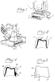
- In Figure 1, a computer installation is denoted by 1. The computer installation can be constituted by a personal computer, e.g. an IBM-compatible personal computer having a type 386 or type 486 processor. The operating system can be constituted by DOS 5.0 type or higher and the internal memory capacity should be at least 2 MB. The computer can expediently be provided with a "mouse"
function 2. Akeyboard terminal 3 havingterminal members 4 should additionally be included. The computer installation is preferably provided with acolour screen 5 and can have an extra I/O card, as it is known. In addition, the computer can comprise a modem which can be integrated in the computer or can constitute a separate unit. The modem is preferably Hayes-compatible and is arranged so as to communicate with a manufacturer via the telecommunications network (the public telecommunications network). For the communications, standard programs can be used, e.g. a Commute 2.0 program from Central Point, which are included with the software. - The computer installation also operates with a CADD-program which is built on the same principles as conventional CAD-programs, but has been adapted and perfected for dental copying and production. The adaptation of standardized CAD-functions has been carried out as described below.
- In Figure 2, a model manufactured by a dentist/dental technician is denoted by 6. The model is aligned in a fixture 7. The fixture, in turn, is disposed on or in a rotary holder, which can additionally be raised and lowered in the directions of the
arrows centre axis 10 of the model. The model is rotated around the said centre axis in the directions of thearrows 11 and 12. The model is turned and vertically displaced, therefore, relative to ascanning device 13, which is longitudinally displaceable along itscentre line 14, but is otherwise fixedly disposed relative to the rotating and rising or sinking model. The model is rotated, during scanning, at 40-100, preferably 50-70 revolutions per minute. The rise for the vertical movement of the model during the rotation can be 0.1-0.4 mm per revolution. Thescanning device 13 therefore comes to track thecontour 15 of the model. The scanning device exhibits a spherical front surface or probe 16, which is physically brought to bear against the surface in the present case. The scanning device operates with great precision as regards the scanning function. The body is scanned, for example, 360 times per revolution, i.e. scanning takes place at each degree of turn. - In accordance with Figures 3 and 4, differently shaped
tooth sleeves tooth material optimal tooth shell shell 18 according to Figure 4 thus contains a thickening 23, which is not evident from the embodiment according to Figure 3. The thickness of the shell can further be varied around the periphery of the model or copy, and the height H of thethickness 23 according to Figure 4 can thus be varied around the periphery, etc. - The CADD-programs operate with representation of vertical sections one by one in accordance with Figure 5, which thus shows a vertical section or
contour 24 extending through thecentre axis 10 according to Figure 2. In known fashion, the contour in question can be varied in size, cf.contours centre axis 10. Theterminal members 3 according to Figure 1 can be actuated to show the said vertical sections one by one on the screen and to advance the various vertical sections or contours in a specific or non-specific order. - Figures 6 and 7 show examples of the structure of the computer installation. This comprises a CPU of the above-specified type.
- A RAM working memory and a hard disk HD are additionally included. The equipment forms a station which can be set up at the place of work of the dentist/dental technician and which can possibly be coordinated with a reading function (not specifically shown here) of models (preparation models). The station has the designation ST. Also forming part of the computer installation is the abovementioned terminal TER. Matching circuits AP1 and AP2 are also included. Via the matching circuit AP1, input data ID are received according to the above. Via the matching unit AP2, output data UD can be dispatched.
- According to Figure 7, the hard disk HD according to Figure 6 comprises memory space DF1 and DF2 for data files for input and output data respectively. Additionally included are a macro model library MB and a data file library DB. The hard disk comprises a matching circuit ANP3, which connects the hard disk HD by a bus connection BF to units corresponding to others mentioned above. Also included is a comparison-making member JF, which is described more closely below. The bus connection can be arranged for 32 or 64 bits. In order to raise the speed of the equipment, the RAM-memory is utilized at full capacity.
- The input data ID are received and stored in a first data file DF1' and the data, output data, to be dispatched from the equipment are disposed correspondingly in a second data file DF2'. The various files have an equivalent format.
- A number of signals generated by means of the actuating members TER' on the terminal TER are shown in Figure 6. The terminal has three parallel connections to the bus so as to offer an illustration of the said signals. By means of first signals i1 generated by one or more first activations of the terminal members TER', the CADD-program is directed to generate, with the aid of the said input data in the data file DF1', representations of the surface of the body in the form of contours of a number of vertical sections extending through the centre axis of the body, cf. Figure 5. By means of second signals i2 generated by one or more second activations of the terminal members, the program is actuated to simulate on the cross-sections/contours concerned an alteration or extension comparable to the body variant, cf. Figures 3, 4 and 12. By means of third signals i3 generated by one or more third activations of the terminal members, the program is directed to store in memory cells DF2 data attributable to that body variant simulated by means of the altered or built-on vertical sections. The said data can form or serve as a basis for the said output data. By means of fourth signals generated by one or more fourth activations of the terminal members, the program is directed to represent a horizontal line, cf. Figures 8, 9 and 10, which horizontal line, in dependence upon the said fourth activations, is controllable in the vertical direction of the vertical sections, as described below. By means of fifth signals i5 and sixth signals i6, the program is directed to attach to a respective vertical section or contour an item of shell-thickness information, so that a shell is presented on the screen for a respective vertical section/contour, cf. Figure 12, or to actuate a connection angle on a respective vertical section, cf. Figures 13-15.
- The hard disk also comprises storage spaces or a library for the saving of macro models and data files which are attributable to different basic types of preparations and teeth, e.g. eye-tooth, front tooth, etc. According to the above, the said saved information serves as a basis for future creations of subsequent simulations and body variant formulations. Characteristic information is stored and can be influenced by acquired experiences of how patients feel about produced products. Information is fed back to the system, e.g. via the terminal TER, by practising dental technicians/dentists, scientists, etc. The library can be configured having a self-learning function of a type which is known per se, which self-learning function means that the said characteristics are constantly being perfected. The said characteristics are applied to a respective model, tooth, etc. currently undergoing copying and model formulation. The preparation boundary on the model can therefore be adapted to the respective tooth type, as well as bulges, heights, extents in the horizontal direction, etc. The implementation can be effected in a manner which is known per se, using program-based measures.
- In Figures 2 and 5, a
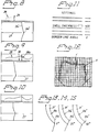
preparation line horizontal line 27 is arranged such that it is displaceable in the vertical direction of the screen by means of the terminal members and the CADD-program. Figures 8, 9 and 10 show various vertical positions of the horizontal line. In the figures, the contour 24' has additionally been enlarged in connection with the position of the preparation line orpreparation boundary 6a''. The line is installed with the aid of the terminal members (keys, mouse, recording members and similar members), so that it intersects thepreparation line 6a'' in the section according to Figure 8. Aline 28 represents the preparation line on the various vertical sections or contours. Avertical line 29 shows the position of the vertical section in question relative to the line. Each section can be represented, in theline 28, by a dot, and it can be seen from Figure 8 that a number of vertical sections have been represented by a number of dots. The representation of the preparation line according to the vertical section in Figure 8 will thus be deposited at theline 29, which can therefore be realized with the aid of the terminal members, etc. Figures 9 and 10 show other sections, and theline 28 shows how the fixing of the preparation line has progressed. - In greater detail, the process proceeds with the operator starting from the main menu in the user program. The data file in question is marked by the use of a band of light at the top the screen. "CADD" is selected from the main menu and, by further actuation of the keys, the data file can be installed in the working memory. The CADD-program is started up and the preparation model is represented, according to Figure 5, on the screen. The image is enlarged in accordance with Figures 8, 9 and 10. The horizontal line can be adjusted on the profiled
edge 6a'' in question, where the dental technician or dentist judges from experience that the preparation line goes. The markings are realized with theline 28. After this, the computer accomplishes the formulation of a subsequent profile, etc. The number of scannings in a respective revolution can total, for example, 36, i.e. every tenth degree. The curve between the dots is interpolated in known fashion, e.g. Lagranges/interpolation formula, Cubic's spine, etc. Following the formulation of thecomplete line 28, assessments can be made of whether the line correctly reproduces the preparation line. The latter should assume a uniformly soft shaping without any sharp portions or edges. If Figure 9 is considered, for example, it can be seen that at 28a there is a sharp deviation of this kind. This should very probably be rectified. This can be realized by the vertical section in question being re-formulated on the screen and a new estimate being made of the preparation line in respect of the particular vertical section. Thescale 30 can here be utilized together with thevertical line 29. - In accordance with the above, the preparation model is rotated slowly whilst scanning proceeds by way of the scanning unit, so that the surface of the model is read along a spiral-shaped line which starts below the preparation line and ends directly above the model. The normal-sized tooth/model which is thus described can be described by a data quantity comprising about 20,000 measurements, which is regarded as a relatively small quantity and allows effective handling in the copying function. The data program transforms the measuring points into a surface, which is converted into a large quantity of vertical sections or contours. The profile of the preparation model can thereby be studied from all angles. The alterations and extensions to the various vertical sections form the basis for the copying function.
- The macro and macro models are utilized as described below. A macro is herein constituted by a macro model plus parameter information relating to the shell or sleeve shaping, the angle at the edge or lip of the shell or sleeve, the vertical position of the supporting edge of the shell or sleeve on the tooth remnant, etc. The respective macro model constitutes a mathematical model which can be integrated or superimposed on the visual display unit with, for example, information (graphs) attributable to the shell/shape of the shell. The respective macro model is attributable to a tooth type (e.g. milk tooth, eye-tooth, etc.), preparation form, etc. The respective macro model is stored in an assigned data file which is filed in a library from which the macro models can be selected by means of terminal members, in a manner which is known per se, by means of the command (the macro name is entered by means of the terminal members in known fashion. Icons, too, can be utilized for the formulation). Correspondingly, different files for read data and calculated data can be arranged for different tooth shapes, preparation shapes, etc. The files can be run together for formulation of desired shapes, so-called "unions", on the visual display unit, by means of which unions options are provided on the screen for the formulation of simultaneous graphic representations. Read data can here be attributable to inner surfaces, outer surfaces, etc. Also, bodies and shapes can be formulated for free merging on the screen (cf. "morphing", as it is known). The files can thereby be merged and different parts of the contours mutually exchanged. This process enables an inner surface file and read wax-hood file, for example, to be merged and tied to a macro model. The manual work which is input in this way can be computer-processed, which opens the way for accuracy in difficult preparation cases/shapes. High accuracy of fit can be obtained, and the handiwork can be maintained by virtue of the computer control having to be managed by a dental technician. The formulated product does not need to be treated.
- The dental technician/dentist is therefore able, in the case involving macro models, to select desired macro models from the library and attach these to graphic representations of shell or sleeve profiles which are formulated on the computer screen in question. The dental technician/dentist is also able to choose shell thickness and sizes of the preparation angles and thereby create extensions, alterations, adaptations, etc., in the originally formulated graphic representation of the shell/sleeve. Those shapes of tooth creations in question which have been worked out in advance and obtained by experience yield major advantages. The advantages relate, inter alia, to handling. The interaction between humans and the computer can be substantially reduced, e.g. when compared with a conventional CAD-function in which the interaction is extensive in the formulation of three-dimensional bodies.
- The read data/files can be attributable to the final shape of the tooth and the current shape of the tooth remnant. By running together and superimposing the information, optimal solutions of the shaping of the supporting body, here referred to as "union", can be achieved. The structure of the shell or sleeve can also be adapted according to the properties of the extension material, which material can be constituted by, for example, porcelain. Choice of colour can also constitute a parameter in this context. References to the preparation line can also serve as a basis for the structure.
- A copied model of the model according to Figure 2 can be realized. Figure 11 shows a menu in which it is possible to construct a
shell 31 according to Figure 12. The menus can therefore comprise "shell thickness" and, by selection of a keyboard option, a desired thickness, e.g. 400 micrometres (0.4 mm), can be chosen. In Figure 12, the thickness is indicated by t'. Using the same menu, an angle can also be chosen at which the copy connects with a preparation line, cf. Figures 13, 14 and 15, which are represented exhibiting files containing macro model, shell and angle. The latter figures show theangles 0°, 20° and 40° respectively. The angles, thickness etc. are or can be dependent upon tooth type (eye-tooth, milk tooth, etc.). The angles in question can be connected, in copying, to the preparation line and optionally chosen from 0° to 40°, starting from a vertical line. This too is stored as macro models in data files and automatically follows the data file. If an angle other than 0° is desired, this can be marked on the menu according to Figure 11 by indicating the number of degrees in the angle function. This can be realized in connection with the indication of the shell thickness, which can itself be altered correspondingly. - The said angles relate to the angles between the free end surface 31b, 31b', 31b'' of the shell and a vertical line. The
depression - In Figure 16, a graphic representation, on the computer screen, of a contour or vertical section of a read surface (inner surface in the representation) is shown by 32. The reading is stored in a first file. On the representation, a
shell 33 has been attached, which shell has been realized using a macro model in the program, which macro model may have been acquired from a second file. The outer surface of the shell has been indicated by 34. The thickness of theshell 33 can be chosen according to the above. In addition, from the macro model library, amacro model representation 35 has been fetched from a third file (by the operator). By formulating different macro models and superimposing this on the shell representation and by working with different shell thicknesses, edge angles at the preparation boundary and/or other parameters such as the defined height of the relief edge on the tooth remnant, the operator (dental technician) is able to effect alterations, adaptations, extensions, etc. to be supplied to the supporting structure (the shell, sleeve, etc.) The adaptation is preferably made with regard to material in the sleeve (e.g. titanium) and the particular extension material 36 (porcelain or other material). Colour, appearance, etc., can here be included as parameters. - Output data according to the above and which constitute the end result of the copying and designing can be disposed in a data file which is dispatched to the manufacturer. The data files of incoming and outbound data are preferably configured in the same format. According to the above, the outbound data file is dispatched by modem, via the public telecommunications network, according to the above.
- A number of basic types of macro models can be utilized in the program in question. A macro model can thus be utilized for the limiting angle function, shell thickness function, edge extent function and edge top function. In addition, the angle function for a recess 6b can be included as a macro model, as are the angle of curvature functions in respect of the said preparation line. The system of coordinates (preferably polar) which is utilized jointly for model reading and manufacture operates with two predictably movable or "locked" parameters and an unpredictably variable or non-"locked" parameter. The one of the said former parameters is constituted by the said rotary movement of the
model 6 according to Figure 2, which rotary movement is 11 or 12 and can, for example, be constant or vary in a predefined manner. The other predictable or "locked" parameter is constituted, in the case according to Figure 2, by the constant displacement of the model in thedirections centre axis 10. The unpredictable parameter is constituted, in the case according to Figure 2, by longitudinal displacement movements of the scanningmember 13 along thelongitudinal axis 14, which are caused by the shaping of thecontour 15. A fourth parameter, which is itself predictable, might be the radius of the scanning probe in question. - The invention is not limited to the embodiment shown by way of example above, but can be subject to modifications within the scope of the subsequent patent claims and the inventive concept.
Claims (14)
- Process for achieving, by means of input data (ID) representing a three-dimensional body (6) usable in the human body, e.g. tooth sleeve, dental bridge or other dental structure, output data (UD) which can be used for manufacturing purposes and represent an altered or extended variant of the body, here referred to as the body variant, which input and output data can be fed to or extracted from a computer installation (1) which exhibits a computer screen (5), operates with a program by means of which an alteration or extension attributable to the body variant can be simulated, and has terminal members (3) (key set, mouse, etc.), by means of which the alteration or extension is effected, characterized in that the input data are read and stored by the computer installation in memory cells (DF1), in that the said program is constituted by a CADD-program and is directed, by means of first signals (i1) generated by one or more first activations of the terminal members (3), to generate, with the aid of the said input data, representations of the surface of the body in the form of contours (24, 24') of a number of vertical sections extending through the centre axis (10) of the body, which contours are presented one at a time on the screen (5), in that the said program is directed, by means of second signals generated by one or more second activations of the terminal members, to simulate on the cross-sections/contours concerned an alteration or extension attributable to the body variant, and in that the program is directed, by means of third signals (i3) generated by one or more third activations of the terminal members, to store in memory cells (DF2) data attributable to the body variant simulated by means of the altered or extended vertical sections, which latter data form or are utilized to generate the said output data (UD).
- Process according to Patent Claim 1, characterized in that the input data are related to information from a system of coordinates in which the body is installed and in which the system of coordinates requires two predictably movable parameters (8, 9 and 11, 12) and one unpredictably variable parameter (14a, 14b).
- Process according to Patent Claim 1 or 2, characterized in that the input data (ID) are disposed in a first data file (DF1) and the output data are disposed in a second data file (DF2') having the same or equivalent format as the first data file.
- Device [sic] according to Patent Claim 1, 2 or 3, characterized in that in the event of alteration (23) or extension to a cross-section which is controlled by means of the said second signals, a reaction takes place according to a control system which is utilized by the program and pays regard to one or more factors or parameters, e.g. tooth type, front and rear of the tooth in question, tooth height, bulging, angle at the preparation line, preparation shapings, etc.
- Process according to any one of the preceding patent claims, characterized in that the program is directed, by means of fourth signals (i4) generated by one or more fourth activations of the terminal members or an associated mouse, to represent a displaceable unit, e.g. a horizontal line (28), which, in dependence upon the said fourth activations, is controllable in the vertical direction of the vertical sections, in that, upon displacement of the unit to a part (6a'') of the respective vertical section representing the preparation line of the body, a line, e.g. a line represented by dots, is generated by the program and presented on the screen (5), which latter line therefore represents the preparation line of the body when the three-dimensional body is applied to a flat surface, and in that data relating to the said preparation line representation (28) form part of the said output data.
- Process according to any one of the preceding patent claims, characterized in that a library (DB) is arranged for the saving of data files attributable to various basic types of teeth, e.g. eye-tooth, front tooth, milk tooth, etc., and other variables, such as, for example, strength, facade material, etc., and in that data, e.g. continuously fed-in data, which are entered under the library function into the said data files are utilized in the creation of each subsequent simulation and body variant formulation such that use can be made of the knowledge, acquired by experience, of whether previous creations have satisfied the requirements or not, and in that comparison-making members (JF) are actuated or activated to conduct comparisons between a body variant currently under formulation and previously formulated body variants.
- Process according to Patent Claim 6, characterized in that the library function (DB, MB) can be performed using a self-teaching function, and in that the optimal shape for the tooth type in question is based upon the total number of body variants created in the equipment and possibly upon experience-based information supplied from outside.
- Process according to any one of the preceding patent claims, characterized in that a number of macro models, which are attained by calculation, experience, etc. and can be arranged in a designated library (MB), are utilized, which macro models utilize rules/mathematics linked, for example, to basic forms of the teeth, the creation of a base type, tooth type, formulation of vertical and circular sections of the respective body variant/tooth, alteration of the height of the tooth in various vertical sections, bulging of the inner and outer sides of the tooth, thickness of a utilized tooth sleeve, etc.
- Process according to any one of the preceding patent claims, characterized in that the program is directed, by means of fifth signals (i5) generated by one or more fifth activations of the terminal members (TER') or an associated mouse function, to attach to a respective vertical section or contour (24, 24') an item of shell-thickness information (t), so that a shell is presented on the screen for a respective vertical section/contour.
- Process according to any one of the preceding patent claims, characterized in that the program is directed, by means of sixth signals (i6) generated by sixth activations of the terminal members (TER'), to influence a connection angle of the respective vertical section, which connection angle is situated at the preparation line and relates to the specific shaping of the connecting surface/connecting lip against a tooth remnant in question.
- Process for achieving, by means of input data (ID) representing a three-dimensional body (6) usable in the human body, e.g. tooth sleeve, dental bridge or other dental structure, output data (UD) which can be used for manufacturing purposes, which input and output data can be fed to or extracted from a computer installation (1), which exhibits a computer screen (5), operates with a program by means of which an adaptation, alteration or extension of the body can be simulated, and has terminal members (3), e.g. in the form of a key set, mouse, etc., by means of which the adaptation, alteration or extension is effected, characterized in that mathematical models, representing macro models, attributable to various forms of the tooth types, e.g. milk tooth, eye-tooth, etc., preparation forms, etc., are formulated by mathematical calculations or on experience-based grounds and are stored in a memory, preferably in assigned files, in that the respective macro model can be extracted by means of terminal or mouse activations on the computer installation so as to be representable on the computer screen, in that the respective representation of the respective macro model can be superimposed on a reading of a sleeve, tooth, preparation, etc., and in that, by means of the said superimposition function, an adaptation, alteration, extension to the said reading is achieved by means of the terminal members/mouse.
- Process for achieving, by means of input data (ID) representing a three-dimensional body (6) usable in the human body, e.g. tooth sleeve, dental bridge or other dental structure, output data (UD) which can be used for manufacturing purposes, which input and output data can be fed to or extracted from a computer installation (1), which exhibits a computer screen (5), operates with a program by means of which an adaptation, alteration or extension of the body can be simulated, and has terminal members (3), e.g. in the form of a key set, mouse, etc., by means of which the adaptation, alteration or extension is effected, according to Patent Claim 11, characterized in that the content of data files for read data/shapes or shapes which have been calculated or acquired by experience are run together and represented together and with one or more macro models on the screen in order to permit the formulation of representations and the realization of output data of adapted, altered, extended body shapes or body variants, and in that, for example, files on a surface/inner surface and read wax-hood information are merged and run together with at least one macro model, which represents a mathematical model attributable to the form of tooth type, preparation, etc., for the formulation of the shape/product/data/processing coordinates in question, the formulation requiring the handiwork skills of the dental technician/dentist, and the computer installation also permitting complicated formulation and preferably facilitating routine work.
- Device for implementing the process according to Claim 1, 11 or 12 for achieving, by means of input data (ID) representing a three-dimensional body usable in the human body, output data (UD), which can be used for manufacturing purposes, e.g. processing coordinates, representing an altered or extended body variant and utilizing a computer installation (1) comprising screen (5), program and terminal members, characterized in that it forms a station (ST), which can be set up at the practice of a dentist/dental technician or equivalent professional category and by means of which the body variant can be simulated by means of the program operating with a CADD-function, in that the station comprises memory storage cells (DF1) for the input data, and in that the CADD-function, in order to reproduce the surface of the body on the screen and in order to permit alteration or extension of the latter according to the body variant, operates with a number of vertical sections, extending through the centre axis of the body, of the body contour or body variant contour (24, 24'), the vertical sections being able to be represented on the screen one at a time, and attachable alterations or extensions related to the alteration or extension of the body variant relative to the body being able to be formulated on the screen, and in that the said memory cells (DF1), or additional memory cells (DF2), are arranged to receive and store data attributable to the altered or extended vertical sections/contours, which data form or serve as a basis for the said output data.
- Device according to Patent Claim 11, characterized in that the input data (ID) are realized by means of a scanning device (13), which comprises a spherical front part/probe (16), and in that the respective vertical section/contour can be represented with the aid of a surface model which can be worked out from the movements of the probe in the system of coordinates (2) of the scanning device, preferably comprising a polar system of coordinates.
Applications Claiming Priority (2)
| Application Number | Priority Date | Filing Date | Title |
|---|---|---|---|
| SE9302399 | 1993-07-12 | ||
| SE9302399A SE501411C2 (en) | 1993-07-12 | 1993-07-12 | Method and apparatus for three-dimensional body useful in the human body |
Publications (2)
| Publication Number | Publication Date |
|---|---|
| EP0643948A1 true EP0643948A1 (en) | 1995-03-22 |
| EP0643948B1 EP0643948B1 (en) | 1999-09-08 |
Family
ID=20390591
Family Applications (1)
| Application Number | Title | Priority Date | Filing Date |
|---|---|---|---|
| EP94850125A Expired - Lifetime EP0643948B1 (en) | 1993-07-12 | 1994-07-05 | Process and device in respect of a three-dimensional body usable in the human body |
Country Status (10)
| Country | Link |
|---|---|
| US (2) | US5587912A (en) |
| EP (1) | EP0643948B1 (en) |
| JP (1) | JP3460741B2 (en) |
| AT (1) | ATE184406T1 (en) |
| CA (1) | CA2127750C (en) |
| DE (1) | DE69420497T2 (en) |
| DK (1) | DK0643948T3 (en) |
| ES (1) | ES2135558T3 (en) |
| GR (1) | GR3031766T3 (en) |
| SE (1) | SE501411C2 (en) |
Cited By (7)
| Publication number | Priority date | Publication date | Assignee | Title |
|---|---|---|---|---|
| WO1998027890A1 (en) * | 1996-12-20 | 1998-07-02 | Dentalmatic Technologies Inc. | Method for producing a dental prosthesis |
| WO1999062422A1 (en) * | 1998-05-29 | 1999-12-09 | Nobel Biocare Ab (Publ) | Method for producing a dental first attachment part for an implant or a second attachment part, and a holder for a model of the first attachment part |
| WO2004044787A2 (en) | 2002-11-11 | 2004-05-27 | Albert Mehl | Method for producing denture parts or for tooth restoration using electronic dental representations |
| EP1782753A2 (en) * | 2004-06-10 | 2007-05-09 | Willytec GmbH | Method and device for producing dentures |
| WO2007119071A1 (en) * | 2006-04-19 | 2007-10-25 | Renishaw Plc | Method of assessing the fit of dental restoration |
| US7899221B2 (en) | 2001-11-08 | 2011-03-01 | Institut Straumann Ag | Devices and methods for producing denture parts |
| WO2012092946A1 (en) | 2011-01-07 | 2012-07-12 | Martin Tank | Method and tooth restoration determination system for determining tooth restorations |
Families Citing this family (344)
| Publication number | Priority date | Publication date | Assignee | Title |
|---|---|---|---|---|
| DE4304570A1 (en) * | 1993-02-16 | 1994-08-18 | Mdc Med Diagnostic Computing | Device and method for preparing and supporting surgical procedures |
| SE501411C2 (en) * | 1993-07-12 | 1995-02-06 | Nobelpharma Ab | Method and apparatus for three-dimensional body useful in the human body |
| SE503498C2 (en) * | 1994-10-04 | 1996-06-24 | Nobelpharma Ab | Method and device for a product intended to be part of the human body and a scanning device for a model for the product |
| CA2150432A1 (en) * | 1995-05-30 | 1996-12-01 | Bert Van Den Berg | Models for computer integrated manufacturing |
| US5766006A (en) | 1995-06-26 | 1998-06-16 | Murljacic; Maryann Lehmann | Tooth shade analyzer system and methods |
| SE507803C2 (en) * | 1996-11-13 | 1998-07-13 | Titanbron Foervaltnings Ab | Method and apparatus for machining a bridge construction |
| US6424877B1 (en) * | 1997-04-04 | 2002-07-23 | Minolta Co., Ltd. | Reproduction apparatus |
| US6073056A (en) * | 1997-04-08 | 2000-06-06 | Larry J. Winget | Method and system for building a data model of a physical part in a data format useful for and reproduction of the part |
| US6094199A (en) * | 1997-05-23 | 2000-07-25 | University Of Washington | 3D objects morphing employing skeletons indicating symmetric differences to define intermediate objects used in morphing |
| US6471511B1 (en) | 1997-06-20 | 2002-10-29 | Align Technology, Inc. | Defining tooth-moving appliances computationally |
| US7247021B2 (en) | 1997-06-20 | 2007-07-24 | Align Technology, Inc. | Subdividing a digital dentition model |
| US7063532B1 (en) | 1997-06-20 | 2006-06-20 | Align Technology, Inc. | Subdividing a digital dentition model |
| US6705863B2 (en) | 1997-06-20 | 2004-03-16 | Align Technology, Inc. | Attachment devices and methods for a dental appliance |
| US8496474B2 (en) | 1997-06-20 | 2013-07-30 | Align Technology, Inc. | Computer automated development of an orthodontic treatment plan and appliance |
| US5975893A (en) | 1997-06-20 | 1999-11-02 | Align Technology, Inc. | Method and system for incrementally moving teeth |
| US6450807B1 (en) | 1997-06-20 | 2002-09-17 | Align Technology, Inc. | System and method for positioning teeth |
| US6409504B1 (en) | 1997-06-20 | 2002-06-25 | Align Technology, Inc. | Manipulating a digital dentition model to form models of individual dentition components |
| AU744385B2 (en) | 1997-06-20 | 2002-02-21 | Align Technology, Inc. | Method and system for incrementally moving teeth |
| US6152731A (en) | 1997-09-22 | 2000-11-28 | 3M Innovative Properties Company | Methods for use in dental articulation |
| IL122807A0 (en) | 1997-12-30 | 1998-08-16 | Cadent Ltd | Virtual orthodontic treatment |
| US9084653B2 (en) | 1998-01-14 | 2015-07-21 | Cadent, Ltd. | Methods for use in dental articulation |
| US6331113B1 (en) * | 1999-01-21 | 2001-12-18 | Dentech, L.L.C. | Automated tooth shade analysis and matching system |
| IL125659A (en) * | 1998-08-05 | 2002-09-12 | Cadent Ltd | Method and apparatus for imaging three-dimensional structure |
| US11026768B2 (en) | 1998-10-08 | 2021-06-08 | Align Technology, Inc. | Dental appliance reinforcement |
| JP3641208B2 (en) | 1998-10-08 | 2005-04-20 | アライン テクノロジー, インコーポレイテッド | Computerized dental treatment planning and instrument development |
| US6802713B1 (en) | 1998-10-08 | 2004-10-12 | Align Technology, Inc. | Defining tooth-moving appliances computationally |
| US6227850B1 (en) | 1999-05-13 | 2001-05-08 | Align Technology, Inc. | Teeth viewing system |
| US6514074B1 (en) | 1999-05-14 | 2003-02-04 | Align Technology, Inc. | Digitally modeling the deformation of gingival |
| US8790118B2 (en) | 1998-11-03 | 2014-07-29 | Shade Analyzing Technologies, Inc. | Interactive dental restorative network |
| WO2000025696A1 (en) * | 1998-11-03 | 2000-05-11 | Shade Analyzing Technologies, Inc. | Interactive dental restorative network |
| US7121825B2 (en) * | 1998-11-30 | 2006-10-17 | Align Technology, Inc. | Tooth positioning appliances and systems |
| ES2367348T3 (en) | 1998-11-30 | 2011-11-02 | Align Technology, Inc. | DEVICES AND FIXING PROCEDURES FOR A DENTAL APPLIANCE. |
| US6572372B1 (en) | 2000-04-25 | 2003-06-03 | Align Technology, Inc. | Embedded features and methods of a dental appliance |
| US6406292B1 (en) | 1999-05-13 | 2002-06-18 | Align Technology, Inc. | System for determining final position of teeth |
| US7108508B2 (en) * | 1998-12-04 | 2006-09-19 | Align Technology, Inc. | Manipulable dental model system for fabrication of a dental appliance |
| US6488499B1 (en) * | 2000-04-25 | 2002-12-03 | Align Technology, Inc. | Methods for correcting deviations in preplanned tooth rearrangements |
| US6227851B1 (en) * | 1998-12-04 | 2001-05-08 | Align Technology, Inc. | Manipulable dental model system for fabrication of a dental appliance |
| US7357636B2 (en) * | 2002-02-28 | 2008-04-15 | Align Technology, Inc. | Manipulable dental model system for fabrication of a dental appliance |
| US6299440B1 (en) * | 1999-01-15 | 2001-10-09 | Align Technology, Inc | System and method for producing tooth movement |
| US7620527B1 (en) * | 1999-05-10 | 2009-11-17 | Johan Leo Alfons Gielis | Method and apparatus for synthesizing and analyzing patterns utilizing novel “super-formula” operator |
| US6602070B2 (en) * | 1999-05-13 | 2003-08-05 | Align Technology, Inc. | Systems and methods for dental treatment planning |
| US6318994B1 (en) | 1999-05-13 | 2001-11-20 | Align Technology, Inc | Tooth path treatment plan |
| CH694571A5 (en) * | 1999-06-21 | 2005-04-15 | Dcs Forschungs & Entwicklungs | A method for producing a dental prosthesis and a dental prosthesis, material for a dental prosthesis and dental prosthesis. |
| US7802987B1 (en) | 1999-12-17 | 2010-09-28 | Align Technology, Inc. | Methods and systems for lubricating dental appliances |
| US6405071B1 (en) | 2000-02-10 | 2002-06-11 | Advanced Research And Technology | Three dimensional imaging and analysis of a root canal |
| US6527550B1 (en) * | 2000-02-15 | 2003-03-04 | Victor J. Hajjar | Apparatus and method for producing a dental prosthetic with a device having a linear rotary bearing |
| US6463344B1 (en) | 2000-02-17 | 2002-10-08 | Align Technology, Inc. | Efficient data representation of teeth model |
| US6633789B1 (en) | 2000-02-17 | 2003-10-14 | Align Technology, Inc. | Effiicient data representation of teeth model |
| US7373286B2 (en) | 2000-02-17 | 2008-05-13 | Align Technology, Inc. | Efficient data representation of teeth model |
| US20020188478A1 (en) | 2000-03-24 | 2002-12-12 | Joe Breeland | Health-care systems and methods |
| US7904307B2 (en) | 2000-03-24 | 2011-03-08 | Align Technology, Inc. | Health-care e-commerce systems and methods |
| WO2001074268A1 (en) | 2000-03-30 | 2001-10-11 | Align Technology, Inc. | System and method for separating three-dimensional models |
| US6454565B2 (en) | 2000-04-25 | 2002-09-24 | Align Technology, Inc. | Systems and methods for varying elastic modulus appliances |
| AU2001255655A1 (en) | 2000-04-25 | 2001-11-07 | Align Technology, Inc. | Treatment analysis systems and methods |
| US6582229B1 (en) * | 2000-04-25 | 2003-06-24 | Align Technology, Inc. | Methods for modeling bite registration |
| US6947038B1 (en) | 2000-04-27 | 2005-09-20 | Align Technology, Inc. | Systems and methods for generating an appliance with tie points |
| US7245977B1 (en) | 2000-07-20 | 2007-07-17 | Align Technology, Inc. | Systems and methods for mass customization |
| US7383198B1 (en) | 2000-07-24 | 2008-06-03 | Align Technology, Inc. | Delivery information systems and methods |
| US7092784B1 (en) | 2000-07-28 | 2006-08-15 | Align Technology | Systems and methods for forming an object |
| US6386878B1 (en) | 2000-08-16 | 2002-05-14 | Align Technology, Inc. | Systems and methods for removing gingiva from teeth |
| US7040896B2 (en) | 2000-08-16 | 2006-05-09 | Align Technology, Inc. | Systems and methods for removing gingiva from computer tooth models |
| US6482284B1 (en) | 2000-08-31 | 2002-11-19 | 3M Innovative Properties Company | Method of making a dental mill blank and support stub assembly |
| US6497574B1 (en) | 2000-09-08 | 2002-12-24 | Align Technology, Inc. | Modified tooth positioning appliances and methods and systems for their manufacture |
| US6607382B1 (en) | 2000-09-21 | 2003-08-19 | Align Technology, Inc. | Methods and systems for concurrent tooth repositioning and substance delivery |
| US6728589B1 (en) | 2000-10-20 | 2004-04-27 | Mallinckrodt Inc. | Customized respiratory mask and method of manufacturing same |
| US6364660B1 (en) * | 2000-10-25 | 2002-04-02 | Duane Milford Durbin | Method and system for imaging and modeling dental structures |
| US6726478B1 (en) | 2000-10-30 | 2004-04-27 | Align Technology, Inc. | Systems and methods for bite-setting teeth models |
| US7736147B2 (en) | 2000-10-30 | 2010-06-15 | Align Technology, Inc. | Systems and methods for bite-setting teeth models |
| EP2261599B1 (en) | 2000-11-08 | 2013-01-02 | Institut Straumann Ag | (Dental) Surface mapping and generation |
| US6783360B2 (en) | 2000-12-13 | 2004-08-31 | Align Technology, Inc. | Systems and methods for positioning teeth |
| US6669875B2 (en) | 2000-12-18 | 2003-12-30 | 3M Innovative Properties Company | Method for making a dental mill blank assembly |
| US7074038B1 (en) | 2000-12-29 | 2006-07-11 | Align Technology, Inc. | Methods and systems for treating teeth |
| US7580846B2 (en) | 2001-01-09 | 2009-08-25 | Align Technology, Inc. | Method and system for distributing patient referrals |
| US7280990B2 (en) * | 2001-08-07 | 2007-10-09 | Ugs Corp. | Method and system for designing and modeling a product in a knowledge based engineering environment |
| US20040202983A1 (en) * | 2001-09-28 | 2004-10-14 | Align Technology, Inc. | Method and kits for forming pontics in polymeric shell aligners |
| US7771195B2 (en) * | 2001-10-29 | 2010-08-10 | Align Technology, Inc. | Polar attachment devices and method for a dental appliance |
| US6767208B2 (en) | 2002-01-10 | 2004-07-27 | Align Technology, Inc. | System and method for positioning teeth |
| US7086860B2 (en) * | 2002-02-20 | 2006-08-08 | Schuman Walter F | Implant placement system |
| US6830450B2 (en) | 2002-04-18 | 2004-12-14 | Align Technology, Inc. | Systems and methods for improved engagement between aligners and teeth |
| US7716024B2 (en) | 2002-04-29 | 2010-05-11 | Geodigm Corporation | Method and apparatus for electronically generating a color dental occlusion map within electronic model images |
| US20030207227A1 (en) * | 2002-05-02 | 2003-11-06 | Align Technology, Inc. | Systems and methods for treating patients |
| US7255558B2 (en) | 2002-06-18 | 2007-08-14 | Cadent, Ltd. | Dental imaging instrument having air stream auxiliary |
| US6979196B2 (en) | 2002-06-21 | 2005-12-27 | Align Technology, Inc. | Systems and methods for automated bite-setting of tooth models |
| WO2004008981A2 (en) * | 2002-07-22 | 2004-01-29 | Cadent Ltd. | A method for defining a finish line of a dental prosthesis |
| US20040243361A1 (en) * | 2002-08-19 | 2004-12-02 | Align Technology, Inc. | Systems and methods for providing mass customization |
| US7156661B2 (en) * | 2002-08-22 | 2007-01-02 | Align Technology, Inc. | Systems and methods for treatment analysis by teeth matching |
| US7077647B2 (en) * | 2002-08-22 | 2006-07-18 | Align Technology, Inc. | Systems and methods for treatment analysis by teeth matching |
| US20040152036A1 (en) * | 2002-09-10 | 2004-08-05 | Amir Abolfathi | Architecture for treating teeth |
| US20040197728A1 (en) * | 2002-09-10 | 2004-10-07 | Amir Abolfathi | Architecture for treating teeth |
| EP2465464B1 (en) | 2002-10-03 | 2018-08-22 | Align Technology, Inc. | A method for preparing a physical model |
| ES2324658T3 (en) | 2002-12-31 | 2009-08-12 | D4D Technologies Llc. | LASER DIGITALIZING SYSTEM FOR DENTAL APPLICATIONS. |
| US7328077B2 (en) * | 2003-01-06 | 2008-02-05 | Duane Milford Durbin | Method and system for automated mass manufacturing of custom tooth die models for use in the fabrication of dental prosthetics |
| US6882894B2 (en) * | 2003-01-06 | 2005-04-19 | Duane Milford Durbin | Method and system for automated mass manufacturing of custom tooth die models for use in the fabrication of dental prosthetics |
| US7600999B2 (en) | 2003-02-26 | 2009-10-13 | Align Technology, Inc. | Systems and methods for fabricating a dental template |
| US20040166463A1 (en) | 2003-02-26 | 2004-08-26 | Align Technology, Inc. | Systems and methods for combination treatments of dental patients |
| US7658610B2 (en) * | 2003-02-26 | 2010-02-09 | Align Technology, Inc. | Systems and methods for fabricating a dental template with a 3-D object placement |
| US20040166462A1 (en) | 2003-02-26 | 2004-08-26 | Align Technology, Inc. | Systems and methods for fabricating a dental template |
| JP5189287B2 (en) | 2003-03-24 | 2013-04-24 | ディーフォーディー テクノロジーズ エルエルシー | Dental laser digitizer system |
| WO2004087000A1 (en) * | 2003-04-03 | 2004-10-14 | Cadent Ltd. | Method and system for fabricating a dental coping, and a coping fabricated thereby |
| WO2004100067A2 (en) * | 2003-04-30 | 2004-11-18 | D3D, L.P. | Intra-oral imaging system |
| US7355721B2 (en) | 2003-05-05 | 2008-04-08 | D4D Technologies, Llc | Optical coherence tomography imaging |
| EP1626671A2 (en) | 2003-05-16 | 2006-02-22 | Nobel Biocare Services AG | Dental implant system |
| US7118374B2 (en) | 2003-06-09 | 2006-10-10 | Ivoclar Vivadent Ag | Enhanced tooth shade guide |
| US7648360B2 (en) * | 2003-07-01 | 2010-01-19 | Align Technology, Inc. | Dental appliance sequence ordering system and method |
| US9642685B2 (en) * | 2003-07-17 | 2017-05-09 | Pentron Clinical Technologies, Llc | Digital technologies for planning and carrying out dental restorative procedures |
| US7030383B2 (en) | 2003-08-04 | 2006-04-18 | Cadent Ltd. | Speckle reduction method and apparatus |
| WO2005027770A2 (en) | 2003-09-17 | 2005-03-31 | D4D Technologies, L.P. | High speed multiple line three-dimensional digitization |
| US7341450B2 (en) * | 2003-10-03 | 2008-03-11 | Shade Analyzing Technologies, Inc. | Tooth shade scan system and method |
| US7361020B2 (en) | 2003-11-19 | 2008-04-22 | Align Technology, Inc. | Dental tray containing radiopaque materials |
| US7118375B2 (en) * | 2004-01-08 | 2006-10-10 | Duane Milford Durbin | Method and system for dental model occlusal determination using a replicate bite registration impression |
| US20050182654A1 (en) * | 2004-02-14 | 2005-08-18 | Align Technology, Inc. | Systems and methods for providing treatment planning |
| US20050186524A1 (en) * | 2004-02-24 | 2005-08-25 | Align Technology, Inc. | Arch expander |
| US7333874B2 (en) | 2004-02-24 | 2008-02-19 | Cadent Ltd. | Method and system for designing and producing dental prostheses and appliances |
| US7904308B2 (en) | 2006-04-18 | 2011-03-08 | Align Technology, Inc. | Method and system for providing indexing and cataloguing of orthodontic related treatment profiles and options |
| US11298209B2 (en) | 2004-02-27 | 2022-04-12 | Align Technology, Inc. | Method and system for providing dynamic orthodontic assessment and treatment profiles |
| US8874452B2 (en) | 2004-02-27 | 2014-10-28 | Align Technology, Inc. | Method and system for providing dynamic orthodontic assessment and treatment profiles |
| US9492245B2 (en) | 2004-02-27 | 2016-11-15 | Align Technology, Inc. | Method and system for providing dynamic orthodontic assessment and treatment profiles |
| US7702492B2 (en) * | 2004-03-11 | 2010-04-20 | Geodigm Corporation | System and method for generating an electronic model for a dental impression having a common coordinate system |
| US7824346B2 (en) * | 2004-03-11 | 2010-11-02 | Geodigm Corporation | Determining condyle displacement utilizing electronic models of dental impressions having a common coordinate system |
| EP1730465B1 (en) * | 2004-03-18 | 2015-05-20 | Renishaw plc | Scanning an object |
| US7241142B2 (en) * | 2004-03-19 | 2007-07-10 | Align Technology, Inc. | Root-based tooth moving sequencing |
| US8260591B2 (en) * | 2004-04-29 | 2012-09-04 | Align Technology, Inc. | Dynamically specifying a view |
| US20050244791A1 (en) * | 2004-04-29 | 2005-11-03 | Align Technology, Inc. | Interproximal reduction treatment planning |
| DE602005009432D1 (en) | 2004-06-17 | 2008-10-16 | Cadent Ltd | Method and apparatus for color forming a three-dimensional structure |
| WO2006009747A1 (en) * | 2004-06-18 | 2006-01-26 | Dentsply International Inc. | Prescribed orthodontic activators |
| KR100672819B1 (en) | 2004-06-24 | 2007-01-22 | 주식회사 케이씨아이 | Driving Apparatus for 3-Dimension Scanning System and 3-Dimension Scanning System for Tooth Modelling Using the Same |
| BRPI0513831A (en) | 2004-07-26 | 2008-05-20 | Dentsply Int Inc | Two-step method of orthodontically correcting misplaced teeth |
| US7322824B2 (en) * | 2004-08-17 | 2008-01-29 | Schmitt Stephen M | Design and manufacture of dental implant restorations |
| US20060141420A1 (en) * | 2004-09-14 | 2006-06-29 | Dentsply Research And Development Corp. | Notched pontic and system for fabricating dental appliance for use therewith |
| US8899976B2 (en) | 2004-09-24 | 2014-12-02 | Align Technology, Inc. | Release agent receptacle |
| SE527666C2 (en) * | 2004-09-30 | 2006-05-02 | Nobel Biocare Ab | Scanner device |
| US7309230B2 (en) | 2004-12-14 | 2007-12-18 | Align Technology, Inc. | Preventing interference between tooth models |
| US20060199145A1 (en) * | 2005-03-07 | 2006-09-07 | Liu Frank Z | Producing physical dental arch model having individually adjustable tooth models |
| US7335024B2 (en) * | 2005-02-03 | 2008-02-26 | Align Technology, Inc. | Methods for producing non-interfering tooth models |
| US20070092853A1 (en) * | 2005-10-24 | 2007-04-26 | Liu Frank Z | Multi-layer casting methods and devices |
| US20060093982A1 (en) * | 2004-11-02 | 2006-05-04 | Huafeng Wen | Method and apparatus for manufacturing and constructing a dental aligner |
| US20060093987A1 (en) * | 2004-11-02 | 2006-05-04 | Huafeng Wen | Producing an adjustable physical dental arch model |
| US7922490B2 (en) | 2004-12-14 | 2011-04-12 | Align Technology, Inc. | Base for physical dental arch model |
| US7384266B2 (en) * | 2004-11-02 | 2008-06-10 | Align Technology, Inc. | Method and apparatus for manufacturing and constructing a physical dental arch model |
| US20060093993A1 (en) * | 2004-11-02 | 2006-05-04 | Huafeng Wen | Producing a base for physical dental arch model |
| US20060199142A1 (en) * | 2005-03-07 | 2006-09-07 | Liu Frank Z | Dental aligner for providing accurate dental treatment |
| US8636513B2 (en) | 2004-12-14 | 2014-01-28 | Align Technology, Inc. | Fabricating a base compatible with physical tooth models |
| US7357634B2 (en) * | 2004-11-05 | 2008-04-15 | Align Technology, Inc. | Systems and methods for substituting virtual dental appliances |
| US20060097422A1 (en) * | 2004-11-08 | 2006-05-11 | Diamond Andrew J | Method for performing surgery and appliances produced thereby |
| US7862336B2 (en) | 2004-11-26 | 2011-01-04 | Cadent Ltd. | Method and system for providing feedback data useful in prosthodontic procedures associated with the intra oral cavity |
| US20060115785A1 (en) | 2004-11-30 | 2006-06-01 | Chunhua Li | Systems and methods for intra-oral drug delivery |
| US7236842B2 (en) * | 2004-12-02 | 2007-06-26 | Cadent Ltd. | System and method for manufacturing a dental prosthesis and a dental prosthesis manufactured thereby |
| US20060147874A1 (en) * | 2005-01-06 | 2006-07-06 | Touchstone C A | Method and apparatus for selecting non-opacious dental materials |
| US7819659B2 (en) | 2005-04-25 | 2010-10-26 | Align Technology, Inc. | System for organizing dental aligners |
| US7448514B2 (en) * | 2005-02-03 | 2008-11-11 | Align Technology, Inc. | Storage system for dental devices |
| WO2006092800A2 (en) | 2005-03-03 | 2006-09-08 | Cadent Ltd. | System and method for scanning an intraoral cavity |
| US7831322B2 (en) * | 2005-03-07 | 2010-11-09 | Align Technology, Inc. | Producing wrinkled dental aligner for dental treatment |
| US8684729B2 (en) * | 2005-03-07 | 2014-04-01 | Align Technology, Inc. | Disposable dental aligner |
| US8337199B2 (en) | 2005-03-07 | 2012-12-25 | Align Technology, Inc. | Fluid permeable dental aligner |
| EP2932935B1 (en) | 2005-03-07 | 2018-07-18 | Align Technology, Inc. | Method of producing fluid-permeable dental aligners |
| US20060275731A1 (en) | 2005-04-29 | 2006-12-07 | Orthoclear Holdings, Inc. | Treatment of teeth by aligners |
| US7555403B2 (en) | 2005-07-15 | 2009-06-30 | Cadent Ltd. | Method for manipulating a dental virtual model, method for creating physical entities based on a dental virtual model thus manipulated, and dental models thus created |
| US20070026358A1 (en) * | 2005-07-26 | 2007-02-01 | Schultz Charles J | Two-phase invisible orthodontics |
| US20070059662A1 (en) * | 2005-09-12 | 2007-03-15 | Tawfik Bittar | Dental device for preparing a tooth for a crown and for preparing the crown and a method of use |
| JP4683390B2 (en) * | 2006-02-15 | 2011-05-18 | 株式会社ジーシー | Production support device |
| US8043091B2 (en) * | 2006-02-15 | 2011-10-25 | Voxelogix Corporation | Computer machined dental tooth system and method |
| US8366442B2 (en) * | 2006-02-15 | 2013-02-05 | Bankruptcy Estate Of Voxelogix Corporation | Dental apparatus for radiographic and non-radiographic imaging |
| JP4892249B2 (en) * | 2006-02-15 | 2012-03-07 | 株式会社ジーシー | Production support device |
| ES2690122T3 (en) * | 2006-02-28 | 2018-11-19 | Ormco Corporation | Software and methods for dental treatment planning |
| ITMI20061114A1 (en) * | 2006-06-09 | 2007-12-10 | Djamel Tebboune | AUTUMATIC WASHING AND-OR TRACKING OF AN OBJECT WITH MULTIPLE COMPONENTS |
| US7844429B2 (en) | 2006-07-19 | 2010-11-30 | Align Technology, Inc. | System and method for three-dimensional complete tooth modeling |
| JP4481279B2 (en) * | 2006-08-17 | 2010-06-16 | 株式会社ジーシー | Data preparation support program for abutment facing surface machining of dental prosthesis |
| US8038444B2 (en) | 2006-08-30 | 2011-10-18 | Align Technology, Inc. | Automated treatment staging for teeth |
| US20080064008A1 (en) * | 2006-09-06 | 2008-03-13 | Dental Implant Technologies, Inc. | Methods for the virtual design and computer manufacture of intra oral devices |
| US7835811B2 (en) * | 2006-10-07 | 2010-11-16 | Voxelogix Corporation | Surgical guides and methods for positioning artificial teeth and dental implants |
| US8209044B2 (en) * | 2006-10-10 | 2012-06-26 | Shofu, Inc. | Modeling data creating system, manufacturing method, and modeling data creating program |
| US9326831B2 (en) | 2006-10-20 | 2016-05-03 | Align Technology, Inc. | System and method for positioning three-dimensional brackets on teeth |
| WO2008051131A1 (en) * | 2006-10-27 | 2008-05-02 | Nobel Biocare Services Ag | Dental model, articulator and methods for production |
| WO2008051129A1 (en) | 2006-10-27 | 2008-05-02 | Nobel Biocare Services Ag | A dental impression tray for use in obtaining an impression of a dental structure |
| US8234000B2 (en) | 2006-10-27 | 2012-07-31 | Nobel Biocare Services Ag | Method and apparatus for obtaining data for a dental component and a physical dental model |
| WO2008066891A2 (en) * | 2006-11-28 | 2008-06-05 | Sensable Technologies, Inc. | Systems for haptic design of dental restorations |
| DE102006061134A1 (en) * | 2006-12-22 | 2008-06-26 | Aepsilon Rechteverwaltungs Gmbh | Process for the transport of dental prostheses |
| DE102006061143A1 (en) * | 2006-12-22 | 2008-07-24 | Aepsilon Rechteverwaltungs Gmbh | Method, computer-readable medium and computer relating to the manufacture of dental prostheses |
| US20080228303A1 (en) * | 2007-03-13 | 2008-09-18 | Schmitt Stephen M | Direct manufacture of dental and medical devices |
| JP5427778B2 (en) * | 2007-05-25 | 2014-02-26 | ノベル バイオケア サーヴィシィズ アーゲー | Method and system for dental planning |
| US7878805B2 (en) | 2007-05-25 | 2011-02-01 | Align Technology, Inc. | Tabbed dental appliance |
| US9060829B2 (en) | 2007-06-08 | 2015-06-23 | Align Technology, Inc. | Systems and method for management and delivery of orthodontic treatment |
| US8591225B2 (en) | 2008-12-12 | 2013-11-26 | Align Technology, Inc. | Tooth movement measurement by automatic impression matching |
| US8562338B2 (en) | 2007-06-08 | 2013-10-22 | Align Technology, Inc. | Treatment progress tracking and recalibration |
| US8075306B2 (en) | 2007-06-08 | 2011-12-13 | Align Technology, Inc. | System and method for detecting deviations during the course of an orthodontic treatment to gradually reposition teeth |
| US20080306724A1 (en) * | 2007-06-08 | 2008-12-11 | Align Technology, Inc. | Treatment planning and progress tracking systems and methods |
| US10342638B2 (en) | 2007-06-08 | 2019-07-09 | Align Technology, Inc. | Treatment planning and progress tracking systems and methods |
| US20090087808A1 (en) * | 2007-09-28 | 2009-04-02 | Reika Ortho Technologies, Inc. | Methods And Systems For Moving Teeth |
| US8738394B2 (en) | 2007-11-08 | 2014-05-27 | Eric E. Kuo | Clinical data file |
| US7914283B2 (en) | 2007-12-06 | 2011-03-29 | Align Technology, Inc. | Activatable dental appliance |
| US8160345B2 (en) | 2008-04-30 | 2012-04-17 | Otismed Corporation | System and method for image segmentation in generating computer models of a joint to undergo arthroplasty |
| JP2011509812A (en) | 2008-01-23 | 2011-03-31 | センサブル テクノロジーズ インコーポレイテッド | Tactile controllable dental modeling system |
| US8899977B2 (en) | 2008-01-29 | 2014-12-02 | Align Technology, Inc. | Orthodontic repositioning appliances having improved geometry, methods and systems |
| US8439672B2 (en) | 2008-01-29 | 2013-05-14 | Align Technology, Inc. | Method and system for optimizing dental aligner geometry |
| US8801725B2 (en) | 2008-03-10 | 2014-08-12 | Zimmer Orthobiologics, Inc. | Instruments and methods used when repairing a defect on a tissue surface |
| US8108189B2 (en) | 2008-03-25 | 2012-01-31 | Align Technologies, Inc. | Reconstruction of non-visible part of tooth |
| US8986009B2 (en) * | 2008-05-08 | 2015-03-24 | Degudent Gmbh | Method for determining 3-D data from at least one prepared maxillary area |
| US9492243B2 (en) | 2008-05-23 | 2016-11-15 | Align Technology, Inc. | Dental implant positioning |
| US9119691B2 (en) | 2008-05-23 | 2015-09-01 | Align Technology, Inc. | Orthodontic tooth movement device, systems and methods |
| US8092215B2 (en) | 2008-05-23 | 2012-01-10 | Align Technology, Inc. | Smile designer |
| US8172569B2 (en) | 2008-06-12 | 2012-05-08 | Align Technology, Inc. | Dental appliance |
| KR101706619B1 (en) | 2008-07-03 | 2017-02-14 | 얼라인 테크널러지, 인크. | Method, apparatus and system for use in dental procedures |
| US8509932B2 (en) | 2008-07-17 | 2013-08-13 | Cadent Ltd. | Methods, systems and accessories useful for procedures relating to dental implants |
| US20100055635A1 (en) | 2008-09-02 | 2010-03-04 | Align Technology, Inc. | Shape engineered aligner - auto shaping |
| US8152518B2 (en) | 2008-10-08 | 2012-04-10 | Align Technology, Inc. | Dental positioning appliance having metallic portion |
| US20100105011A1 (en) * | 2008-10-29 | 2010-04-29 | Inpronto Inc. | System, Method And Apparatus For Tooth Implant Planning And Tooth Implant Kits |
| US8083522B2 (en) * | 2008-10-29 | 2011-12-27 | Inpronto Inc. | Method for tooth implants |
| JP6058889B2 (en) | 2008-11-20 | 2017-01-11 | アライン テクノロジー, インコーポレイテッド | Orthodontic system and method including parametric attachment |
| US8936463B2 (en) | 2008-11-24 | 2015-01-20 | Align Technology, Inc. | Dental appliance with simulated teeth and method for making |
| US20100129763A1 (en) * | 2008-11-24 | 2010-05-27 | Align Technology, Inc. | Sequential sports guard |
| US8401686B2 (en) | 2008-12-18 | 2013-03-19 | Align Technology, Inc. | Reduced registration bonding template |
| US9642678B2 (en) | 2008-12-30 | 2017-05-09 | Align Technology, Inc. | Method and system for dental visualization |
| US8382474B2 (en) | 2008-12-31 | 2013-02-26 | Cadent Ltd. | Dental articulator |
| US20100291505A1 (en) * | 2009-01-23 | 2010-11-18 | Curt Rawley | Haptically Enabled Coterminous Production of Prosthetics and Patient Preparations in Medical and Dental Applications |
| US8936464B2 (en) | 2009-02-24 | 2015-01-20 | Cadent Ltd. | Method, system and model for indirect bonding |
| US8292617B2 (en) | 2009-03-19 | 2012-10-23 | Align Technology, Inc. | Dental wire attachment |
| US8765031B2 (en) | 2009-08-13 | 2014-07-01 | Align Technology, Inc. | Method of forming a dental appliance |
| US8348669B1 (en) | 2009-11-04 | 2013-01-08 | Bankruptcy Estate Of Voxelogix Corporation | Surgical template and method for positioning dental casts and dental implants |
| US8708697B2 (en) | 2009-12-08 | 2014-04-29 | Align Technology, Inc. | Tactile objects for orthodontics, systems and methods |
| JP5557533B2 (en) * | 2010-01-18 | 2014-07-23 | 株式会社ジーシー | Production support apparatus, production support method, and production support program |
| US9375303B1 (en) | 2010-04-15 | 2016-06-28 | Zimmer, Inc. | Methods of ordering and manufacturing orthopedic components |
| US9241774B2 (en) | 2010-04-30 | 2016-01-26 | Align Technology, Inc. | Patterned dental positioning appliance |
| US20110269092A1 (en) | 2010-04-30 | 2011-11-03 | Align Technology, Inc. | Reinforced aligner hooks |
| US9211166B2 (en) | 2010-04-30 | 2015-12-15 | Align Technology, Inc. | Individualized orthodontic treatment index |
| US9173724B2 (en) | 2010-06-25 | 2015-11-03 | Kabushiki Kaisha Shofu | Occlusal adjustment system |
| ES2848157T3 (en) | 2010-07-19 | 2021-08-05 | Align Technology Inc | Procedures and systems for creating and interacting with three-dimensional virtual models |
| US8435305B2 (en) | 2010-08-31 | 2013-05-07 | Zimmer, Inc. | Osteochondral graft delivery device and uses thereof |
| DK2663254T3 (en) | 2011-01-13 | 2020-08-31 | Align Technology Inc | Methods, systems and accessories that can be used for dental implant procedures |
| US9108338B2 (en) | 2011-04-13 | 2015-08-18 | Align Technology, Inc. | Methods and systems for thermal forming an object |
| US9125709B2 (en) | 2011-07-29 | 2015-09-08 | Align Technology, Inc. | Systems and methods for tracking teeth movement during orthodontic treatment |
| US9403238B2 (en) | 2011-09-21 | 2016-08-02 | Align Technology, Inc. | Laser cutting |
| US8641414B2 (en) | 2011-10-10 | 2014-02-04 | Align Technology, Inc. | Automatic placement of precision cuts |
| EP3451298A3 (en) | 2011-12-14 | 2019-06-05 | Stryker European Holdings I, LLC | Technique for generating a bone plate design |
| US9375300B2 (en) | 2012-02-02 | 2016-06-28 | Align Technology, Inc. | Identifying forces on a tooth |
| US9022781B2 (en) | 2012-02-15 | 2015-05-05 | Align Technology, Inc. | Orthodontic appliances that accommodate incremental and continuous tooth movement, systems and methods |
| US9375298B2 (en) | 2012-02-21 | 2016-06-28 | Align Technology, Inc. | Dental models and related methods |
| US9220580B2 (en) | 2012-03-01 | 2015-12-29 | Align Technology, Inc. | Determining a dental treatment difficulty |
| US9655691B2 (en) | 2012-05-14 | 2017-05-23 | Align Technology, Inc. | Multilayer dental appliances and related methods and systems |
| US9414897B2 (en) | 2012-05-22 | 2016-08-16 | Align Technology, Inc. | Adjustment of tooth position in a virtual dental model |
| US20140067334A1 (en) | 2012-09-06 | 2014-03-06 | Align Technology Inc. | Method and a system usable in creating a subsequent dental appliance |
| US8986003B2 (en) | 2012-09-13 | 2015-03-24 | Orthoaccel Technologies, Inc. | Pearlescent white aligners |
| AU2013318708A1 (en) | 2012-09-24 | 2015-04-09 | The Antenna Company International N.V. | Lens antenna, method of manufacturing and using such an antenna, and antenna system |
| US9668829B2 (en) | 2012-12-19 | 2017-06-06 | Align Technology, Inc. | Methods and systems for dental procedures |
| US10617489B2 (en) | 2012-12-19 | 2020-04-14 | Align Technology, Inc. | Creating a digital dental model of a patient's teeth using interproximal information |
| US10912571B2 (en) | 2013-03-15 | 2021-02-09 | Howmedica Osteonics Corporation | Generation of a mating surface model for patient specific cutting guide based on anatomical model segmentation |
| US9393087B2 (en) | 2013-08-01 | 2016-07-19 | Align Technology, Inc. | Methods and systems for generating color images |
| US10555792B2 (en) | 2014-01-31 | 2020-02-11 | Align Technology, Inc. | Direct fabrication of orthodontic appliances with elastics |
| US11497586B2 (en) | 2014-03-21 | 2022-11-15 | Align Technology, Inc. | Segmented orthodontic appliance with elastics |
| US10758323B2 (en) | 2014-01-31 | 2020-09-01 | Align Technology, Inc. | Orthodontic appliances with elastics |
| US9844424B2 (en) | 2014-02-21 | 2017-12-19 | Align Technology, Inc. | Dental appliance with repositioning jaw elements |
| US10537406B2 (en) | 2014-02-21 | 2020-01-21 | Align Technology, Inc. | Dental appliance with repositioning jaw elements |
| US10299894B2 (en) | 2014-02-21 | 2019-05-28 | Align Technology, Inc. | Treatment plan specific bite adjustment structures |
| US10128572B2 (en) | 2014-03-26 | 2018-11-13 | The Antenna Company International N.V. | Patch antenna, method of manufacturing and using such an antenna, and antenna system |
| US10016262B2 (en) | 2014-06-16 | 2018-07-10 | Align Technology, Inc. | Unitary dental model |
| CN106572894A (en) | 2014-06-20 | 2017-04-19 | 阿莱恩技术有限公司 | Elastic-coated orthodontic appliance |
| EP3875053A1 (en) | 2014-06-20 | 2021-09-08 | Align Technology, Inc. | Aligners with elastic layer |
| US9261358B2 (en) * | 2014-07-03 | 2016-02-16 | Align Technology, Inc. | Chromatic confocal system |
| US9261356B2 (en) | 2014-07-03 | 2016-02-16 | Align Technology, Inc. | Confocal surface topography measurement with fixed focal positions |
| US9439568B2 (en) | 2014-07-03 | 2016-09-13 | Align Technology, Inc. | Apparatus and method for measuring surface topography optically |
| EP3167411A1 (en) * | 2014-07-07 | 2017-05-17 | Siemens Aktiengesellschaft | Method and device for determining an optimum manufacturing alternative for manufacturing a product |
| US10772506B2 (en) | 2014-07-07 | 2020-09-15 | Align Technology, Inc. | Apparatus for dental confocal imaging |
| US9693839B2 (en) | 2014-07-17 | 2017-07-04 | Align Technology, Inc. | Probe head and apparatus for intraoral confocal imaging using polarization-retarding coatings |
| US9675430B2 (en) | 2014-08-15 | 2017-06-13 | Align Technology, Inc. | Confocal imaging apparatus with curved focal surface |
| US9724177B2 (en) | 2014-08-19 | 2017-08-08 | Align Technology, Inc. | Viewfinder with real-time tracking for intraoral scanning |
| US9660418B2 (en) | 2014-08-27 | 2017-05-23 | Align Technology, Inc. | VCSEL based low coherence emitter for confocal 3D scanner |
| US10449016B2 (en) | 2014-09-19 | 2019-10-22 | Align Technology, Inc. | Arch adjustment appliance |
| US9610141B2 (en) | 2014-09-19 | 2017-04-04 | Align Technology, Inc. | Arch expanding appliance |
| US11147652B2 (en) | 2014-11-13 | 2021-10-19 | Align Technology, Inc. | Method for tracking, predicting, and proactively correcting malocclusion and related issues |
| US9744001B2 (en) | 2014-11-13 | 2017-08-29 | Align Technology, Inc. | Dental appliance with cavity for an unerupted or erupting tooth |
| US20160193014A1 (en) | 2015-01-05 | 2016-07-07 | Align Technology, Inc. | Method to modify aligner by modifying tooth position |
| US10588776B2 (en) | 2015-01-13 | 2020-03-17 | Align Technology, Inc. | Systems, methods, and devices for applying distributed forces for mandibular advancement |
| US10517701B2 (en) | 2015-01-13 | 2019-12-31 | Align Technology, Inc. | Mandibular advancement and retraction via bone anchoring devices |
| US10537463B2 (en) | 2015-01-13 | 2020-01-21 | Align Technology, Inc. | Systems and methods for positioning a patient's mandible in response to sleep apnea status |
| US10504386B2 (en) | 2015-01-27 | 2019-12-10 | Align Technology, Inc. | Training method and system for oral-cavity-imaging-and-modeling equipment |
| EP4241726A3 (en) | 2015-02-23 | 2023-12-13 | Align Technology, Inc. | System and method to manufacture aligner by modifying tooth position |
| EP3261579B1 (en) | 2015-02-23 | 2023-06-07 | Align Technology, Inc. | Primer aligner stages for lag issue resolution in low-stage clear aligner treatments |
| US11850111B2 (en) | 2015-04-24 | 2023-12-26 | Align Technology, Inc. | Comparative orthodontic treatment planning tool |
| US10743964B2 (en) | 2015-07-07 | 2020-08-18 | Align Technology, Inc. | Dual aligner assembly |
| US10201409B2 (en) | 2015-07-07 | 2019-02-12 | Align Technology, Inc. | Dental appliance having ornamental design |
| US10363116B2 (en) | 2015-07-07 | 2019-07-30 | Align Technology, Inc. | Direct fabrication of power arms |
| US11045282B2 (en) | 2015-07-07 | 2021-06-29 | Align Technology, Inc. | Direct fabrication of aligners with interproximal force coupling |
| US10959810B2 (en) | 2015-07-07 | 2021-03-30 | Align Technology, Inc. | Direct fabrication of aligners for palate expansion and other applications |
| US11642194B2 (en) | 2015-07-07 | 2023-05-09 | Align Technology, Inc. | Multi-material aligners |
| US10492888B2 (en) | 2015-07-07 | 2019-12-03 | Align Technology, Inc. | Dental materials using thermoset polymers |
| US10248883B2 (en) | 2015-08-20 | 2019-04-02 | Align Technology, Inc. | Photograph-based assessment of dental treatments and procedures |
| US11931222B2 (en) | 2015-11-12 | 2024-03-19 | Align Technology, Inc. | Dental attachment formation structures |
| US11554000B2 (en) | 2015-11-12 | 2023-01-17 | Align Technology, Inc. | Dental attachment formation structure |
| US11103330B2 (en) | 2015-12-09 | 2021-08-31 | Align Technology, Inc. | Dental attachment placement structure |
| US11596502B2 (en) | 2015-12-09 | 2023-03-07 | Align Technology, Inc. | Dental attachment placement structure |
| US10045835B2 (en) | 2016-02-17 | 2018-08-14 | Align Technology, Inc. | Variable direction tooth attachments |
| WO2017218947A1 (en) | 2016-06-17 | 2017-12-21 | Align Technology, Inc. | Intraoral appliances with sensing |
| US10383705B2 (en) | 2016-06-17 | 2019-08-20 | Align Technology, Inc. | Orthodontic appliance performance monitor |
| DK3578131T3 (en) | 2016-07-27 | 2020-12-21 | Align Technology Inc | Intraoral scanner with dental diagnostic features |
| US10507087B2 (en) | 2016-07-27 | 2019-12-17 | Align Technology, Inc. | Methods and apparatuses for forming a three-dimensional volumetric model of a subject's teeth |
| WO2018039383A1 (en) | 2016-08-24 | 2018-03-01 | Align Technology, Inc. | Method to visualize and manufacture aligner by modifying tooth position |
| WO2018085718A2 (en) | 2016-11-04 | 2018-05-11 | Align Technology, Inc. | Methods and apparatuses for dental images |
| WO2018102770A1 (en) | 2016-12-02 | 2018-06-07 | Align Technology, Inc. | Force control, stop mechanism, regulating structure of removable arch adjustment appliance |
| CN110035708B (en) | 2016-12-02 | 2021-11-05 | 阿莱恩技术有限公司 | Palatal expander and method of expanding a palate |
| AU2017366755B2 (en) | 2016-12-02 | 2022-07-28 | Align Technology, Inc. | Methods and apparatuses for customizing rapid palatal expanders using digital models |
| WO2018102702A1 (en) | 2016-12-02 | 2018-06-07 | Align Technology, Inc. | Dental appliance features for speech enhancement |
| US10548700B2 (en) | 2016-12-16 | 2020-02-04 | Align Technology, Inc. | Dental appliance etch template |
| US11166788B2 (en) | 2016-12-19 | 2021-11-09 | Align Technology, Inc. | Aligners with enhanced gable bends |
| US11071608B2 (en) | 2016-12-20 | 2021-07-27 | Align Technology, Inc. | Matching assets in 3D treatment plans |
| US10456043B2 (en) | 2017-01-12 | 2019-10-29 | Align Technology, Inc. | Compact confocal dental scanning apparatus |
| US10779718B2 (en) | 2017-02-13 | 2020-09-22 | Align Technology, Inc. | Cheek retractor and mobile device holder |
| US10973611B2 (en) | 2017-03-20 | 2021-04-13 | Align Technology, Inc. | Generating a virtual depiction of an orthodontic treatment of a patient |
| US10613515B2 (en) | 2017-03-31 | 2020-04-07 | Align Technology, Inc. | Orthodontic appliances including at least partially un-erupted teeth and method of forming them |
| US10667867B2 (en) | 2017-05-03 | 2020-06-02 | Stryker European Holdings I, Llc | Methods of pose estimation of three-dimensional bone models in surgical planning a total ankle replacement |
| US11045283B2 (en) | 2017-06-09 | 2021-06-29 | Align Technology, Inc. | Palatal expander with skeletal anchorage devices |
| WO2019005808A1 (en) | 2017-06-26 | 2019-01-03 | Align Technology, Inc. | Biosensor performance indicator for intraoral appliances |
| WO2019006416A1 (en) | 2017-06-30 | 2019-01-03 | Align Technology, Inc. | Computer implemented method and system for designing and/or manufacturing orthodontic appliances for treating or preventing temporomandibular joint dysfunction |
| US11793606B2 (en) | 2017-06-30 | 2023-10-24 | Align Technology, Inc. | Devices, systems, and methods for dental arch expansion |
| US10885521B2 (en) | 2017-07-17 | 2021-01-05 | Align Technology, Inc. | Method and apparatuses for interactive ordering of dental aligners |
| CN111107806B (en) | 2017-07-21 | 2022-04-19 | 阿莱恩技术有限公司 | Jaw profile anchoring |
| WO2019023461A1 (en) | 2017-07-27 | 2019-01-31 | Align Technology, Inc. | Tooth shading, transparency and glazing |
| EP4278957A3 (en) | 2017-07-27 | 2024-01-24 | Align Technology, Inc. | System and methods for processing an orthodontic aligner by means of an optical coherence tomography |
| WO2019035979A1 (en) | 2017-08-15 | 2019-02-21 | Align Technology, Inc. | Buccal corridor assessment and computation |
| WO2019036514A1 (en) | 2017-08-17 | 2019-02-21 | Align Technology, Inc. | Systems, methods, and apparatus for correcting malocclusions of teeth |
| WO2019036677A1 (en) | 2017-08-17 | 2019-02-21 | Align Technology, Inc. | Dental appliance compliance monitoring |
| US10813720B2 (en) | 2017-10-05 | 2020-10-27 | Align Technology, Inc. | Interproximal reduction templates |
| EP3700458B1 (en) | 2017-10-27 | 2023-06-07 | Align Technology, Inc. | Alternative bite adjustment structures |
| CN111295153B (en) | 2017-10-31 | 2023-06-16 | 阿莱恩技术有限公司 | Dental appliance with selective bite loading and controlled tip staggering |
| EP3703607A2 (en) | 2017-11-01 | 2020-09-09 | Align Technology, Inc. | Automatic treatment planning |
| US11737857B2 (en) | 2017-11-01 | 2023-08-29 | Align Technology, Inc. | Systems and methods for correcting malocclusions of teeth |
| WO2019100022A1 (en) | 2017-11-17 | 2019-05-23 | Align Technology, Inc. | Orthodontic retainers |
| EP3716885B1 (en) | 2017-11-30 | 2023-08-30 | Align Technology, Inc. | Orthodontic intraoral appliances comprising sensors |
| WO2019118876A1 (en) | 2017-12-15 | 2019-06-20 | Align Technology, Inc. | Closed loop adaptive orthodontic treatment methods and apparatuses |
| US10980613B2 (en) | 2017-12-29 | 2021-04-20 | Align Technology, Inc. | Augmented reality enhancements for dental practitioners |
| AU2019212649A1 (en) | 2018-01-26 | 2020-07-02 | Align Technology, Inc. | Diagnostic intraoral scanning and tracking |
| US10952816B2 (en) | 2018-01-26 | 2021-03-23 | Align Technology, Inc. | Visual prosthetic and orthodontic treatment planning |
| CN108247055B (en) * | 2018-02-12 | 2019-01-29 | 成都优材科技有限公司 | The digitlization integrated molding method of dentistry attachment |
| US11937991B2 (en) | 2018-03-27 | 2024-03-26 | Align Technology, Inc. | Dental attachment placement structure |
| CN116211501A (en) | 2018-04-11 | 2023-06-06 | 阿莱恩技术有限公司 | Palate expander, palate expander device and system, and method for forming palate expander |
| JP7437320B2 (en) | 2018-05-04 | 2024-02-22 | アライン テクノロジー, インコーポレイテッド | Curable compositions and methods of producing crosslinked polymers therefrom for use in high temperature lithography-based photopolymerization processes |
| US11026766B2 (en) | 2018-05-21 | 2021-06-08 | Align Technology, Inc. | Photo realistic rendering of smile image after treatment |
| US11553988B2 (en) | 2018-06-29 | 2023-01-17 | Align Technology, Inc. | Photo of a patient with new simulated smile in an orthodontic treatment review software |
| WO2020005386A1 (en) | 2018-06-29 | 2020-01-02 | Align Technology, Inc. | Providing a simulated outcome of dental treatment on a patient |
| US10835349B2 (en) | 2018-07-20 | 2020-11-17 | Align Technology, Inc. | Parametric blurring of colors for teeth in generated images |
| EP3899984A1 (en) | 2018-12-21 | 2021-10-27 | The Procter & Gamble Company | Apparatus and method for operating a personal grooming appliance or household cleaning appliance |
| US11478334B2 (en) | 2019-01-03 | 2022-10-25 | Align Technology, Inc. | Systems and methods for nonlinear tooth modeling |
| CN116650153A (en) | 2019-01-03 | 2023-08-29 | 阿莱恩技术有限公司 | Automatic appliance design using robust parameter optimization method |
| US11779243B2 (en) | 2019-01-07 | 2023-10-10 | Align Technology, Inc. | Customized aligner change indicator |
| EP4282377A3 (en) | 2019-05-14 | 2024-02-28 | Align Technology, Inc. | Visual presentation of gingival line generated based on 3d tooth model |
| US11622836B2 (en) | 2019-12-31 | 2023-04-11 | Align Technology, Inc. | Aligner stage analysis to obtain mechanical interactions of aligners and teeth for treatment planning |
Citations (3)
| Publication number | Priority date | Publication date | Assignee | Title |
|---|---|---|---|---|
| EP0376873A2 (en) * | 1988-12-30 | 1990-07-04 | Aaron Shafir | Apparatus for digitizing the contour of a dental surface, particularly useful for preparing a dental crown |
| EP0490848A2 (en) * | 1990-12-12 | 1992-06-17 | Nobelpharma AB | A procedure and apparatus for producing individually designed, three-dimensional bodies usable as tooth replacements, prostheses, etc. |
| EP0541500A1 (en) * | 1991-11-01 | 1993-05-12 | Nobelpharma AB | Scanning device |
Family Cites Families (16)
| Publication number | Priority date | Publication date | Assignee | Title |
|---|---|---|---|---|
| CH596949A5 (en) * | 1975-09-30 | 1978-03-31 | Siemens Ag | |
| US4394608A (en) * | 1980-11-20 | 1983-07-19 | Gettys Manufacturing Co., Inc. | Machine tool tracing system |
| US4575805A (en) * | 1980-12-24 | 1986-03-11 | Moermann Werner H | Method and apparatus for the fabrication of custom-shaped implants |
| FR2536654B1 (en) * | 1982-11-30 | 1987-01-09 | Duret Francois | METHOD FOR PRODUCING A DENTAL PROSTHESIS |
| US4663720A (en) * | 1984-02-21 | 1987-05-05 | Francois Duret | Method of and apparatus for making a prosthesis, especially a dental prosthesis |
| DE3804743A1 (en) * | 1988-02-16 | 1989-08-24 | Heidenhain Gmbh Dr Johannes | REQUIREMENT |
| US5313400A (en) * | 1989-02-14 | 1994-05-17 | Fanuc Ltd. | Tracing method |
| US5128870A (en) * | 1989-06-09 | 1992-07-07 | Regents Of The University Of Minnesota | Automated high-precision fabrication of objects of complex and unique geometry |
| US5027281A (en) * | 1989-06-09 | 1991-06-25 | Regents Of The University Of Minnesota | Method and apparatus for scanning and recording of coordinates describing three dimensional objects of complex and unique geometry |
| US5184306A (en) * | 1989-06-09 | 1993-02-02 | Regents Of The University Of Minnesota | Automated high-precision fabrication of objects of complex and unique geometry |
| JPH07104146B2 (en) * | 1989-08-29 | 1995-11-13 | 株式会社ミツトヨ | Rotation table scanning control method for coordinate measuring probe |
| JPH03184749A (en) * | 1989-12-11 | 1991-08-12 | Fanuc Ltd | Profile controller for rotator |
| US5224049A (en) * | 1990-04-10 | 1993-06-29 | Mushabac David R | Method, system and mold assembly for use in preparing a dental prosthesis |
| US5273429A (en) * | 1992-04-03 | 1993-12-28 | Foster-Miller, Inc. | Method and apparatus for modeling a dental prosthesis |
| NL9200642A (en) * | 1992-04-06 | 1993-11-01 | Elephant Holding Bv | METHOD FOR MANUFACTURING A DENTAL PROSTHESIS |
| SE501411C2 (en) * | 1993-07-12 | 1995-02-06 | Nobelpharma Ab | Method and apparatus for three-dimensional body useful in the human body |
-
1993
- 1993-07-12 SE SE9302399A patent/SE501411C2/en not_active IP Right Cessation
-
1994
- 1994-07-05 ES ES94850125T patent/ES2135558T3/en not_active Expired - Lifetime
- 1994-07-05 EP EP94850125A patent/EP0643948B1/en not_active Expired - Lifetime
- 1994-07-05 DK DK94850125T patent/DK0643948T3/en active
- 1994-07-05 AT AT94850125T patent/ATE184406T1/en active
- 1994-07-05 DE DE69420497T patent/DE69420497T2/en not_active Expired - Lifetime
- 1994-07-07 US US08/271,457 patent/US5587912A/en not_active Expired - Lifetime
- 1994-07-11 CA CA002127750A patent/CA2127750C/en not_active Expired - Fee Related
- 1994-07-11 JP JP18293994A patent/JP3460741B2/en not_active Expired - Fee Related
-
1996
- 1996-12-03 US US08/760,161 patent/US5880962A/en not_active Expired - Lifetime
-
1999
- 1999-11-05 GR GR990402856T patent/GR3031766T3/en unknown
Patent Citations (3)
| Publication number | Priority date | Publication date | Assignee | Title |
|---|---|---|---|---|
| EP0376873A2 (en) * | 1988-12-30 | 1990-07-04 | Aaron Shafir | Apparatus for digitizing the contour of a dental surface, particularly useful for preparing a dental crown |
| EP0490848A2 (en) * | 1990-12-12 | 1992-06-17 | Nobelpharma AB | A procedure and apparatus for producing individually designed, three-dimensional bodies usable as tooth replacements, prostheses, etc. |
| EP0541500A1 (en) * | 1991-11-01 | 1993-05-12 | Nobelpharma AB | Scanning device |
Cited By (15)
| Publication number | Priority date | Publication date | Assignee | Title |
|---|---|---|---|---|
| US6398554B1 (en) * | 1996-12-20 | 2002-06-04 | Dentalmatic Technologies Inc. | Process for producing a dental prosthesis |
| WO1998027890A1 (en) * | 1996-12-20 | 1998-07-02 | Dentalmatic Technologies Inc. | Method for producing a dental prosthesis |
| WO1999062422A1 (en) * | 1998-05-29 | 1999-12-09 | Nobel Biocare Ab (Publ) | Method for producing a dental first attachment part for an implant or a second attachment part, and a holder for a model of the first attachment part |
| US7899221B2 (en) | 2001-11-08 | 2011-03-01 | Institut Straumann Ag | Devices and methods for producing denture parts |
| WO2004044787A2 (en) | 2002-11-11 | 2004-05-27 | Albert Mehl | Method for producing denture parts or for tooth restoration using electronic dental representations |
| DE10252298B3 (en) * | 2002-11-11 | 2004-08-19 | Mehl, Albert, Prof. Dr. Dr. | Process for the production of tooth replacement parts or tooth restorations using electronic tooth representations |
| US8727776B2 (en) | 2002-11-11 | 2014-05-20 | Sirona Dental Systems Gmbh | Method for producing denture parts or for tooth restoration using electronic dental representations |
| EP3091454A1 (en) | 2002-11-11 | 2016-11-09 | Sirona Dental Systems GmbH | Method for producing denture parts or tooth restorations using electronic dental representations |
| US9672444B2 (en) | 2002-11-11 | 2017-06-06 | Dentsply International Inc. | Method for producing denture parts or for tooth restoration using electronic dental representations |
| EP1782753A2 (en) * | 2004-06-10 | 2007-05-09 | Willytec GmbH | Method and device for producing dentures |
| EP1782752A3 (en) * | 2004-06-10 | 2007-06-20 | Aepsilon Rechteverwaltungs GmbH | Method and device for producing dentures |
| EP1782753A3 (en) * | 2004-06-10 | 2007-07-04 | Aepsilon Rechteverwaltungs GmbH | Method and device for producing dentures |
| WO2007119071A1 (en) * | 2006-04-19 | 2007-10-25 | Renishaw Plc | Method of assessing the fit of dental restoration |
| WO2012092946A1 (en) | 2011-01-07 | 2012-07-12 | Martin Tank | Method and tooth restoration determination system for determining tooth restorations |
| DE102011008074A1 (en) | 2011-01-07 | 2012-07-12 | Martin Tank | Method and dental restorative system for determining dental restorations |
Also Published As
| Publication number | Publication date |
|---|---|
| US5587912A (en) | 1996-12-24 |
| SE9302399L (en) | 1995-01-13 |
| EP0643948B1 (en) | 1999-09-08 |
| DK0643948T3 (en) | 2000-03-27 |
| CA2127750A1 (en) | 1995-01-13 |
| ATE184406T1 (en) | 1999-09-15 |
| CA2127750C (en) | 2005-04-12 |
| JP3460741B2 (en) | 2003-10-27 |
| DE69420497D1 (en) | 1999-10-14 |
| GR3031766T3 (en) | 2000-02-29 |
| SE501411C2 (en) | 1995-02-06 |
| JPH07152822A (en) | 1995-06-16 |
| ES2135558T3 (en) | 1999-11-01 |
| SE9302399D0 (en) | 1993-07-12 |
| DE69420497T2 (en) | 2000-04-06 |
| US5880962A (en) | 1999-03-09 |
Similar Documents
| Publication | Publication Date | Title |
|---|---|---|
| EP0643948B1 (en) | Process and device in respect of a three-dimensional body usable in the human body | |
| JP6949932B2 (en) | Computer-executed dental restoration design | |
| US7474932B2 (en) | Dental computer-aided design (CAD) methods and systems | |
| DK1581896T3 (en) | Process for the preparation of tooth replacement parts or tooth restorations using electronic dental representations | |
| US7488174B2 (en) | Method for defining a finish line of a dental prosthesis | |
| US8359114B2 (en) | Haptically enabled dental modeling system | |
| US20080261165A1 (en) | Systems for haptic design of dental restorations | |
| US20060003292A1 (en) | Digital manufacturing of removable oral appliances | |
| US20100291505A1 (en) | Haptically Enabled Coterminous Production of Prosthetics and Patient Preparations in Medical and Dental Applications | |
| US20230005196A1 (en) | Method for generating edge curve for dental devices | |
| WO2008128700A1 (en) | Computer-assisted creation of a custom tooth set-up using facial analysis | |
| EP3801361B1 (en) | Methods of digitally designing artificial teeth | |
| Beers et al. | Computer‐assisted treatment planning and analysis | |
| CN105078598A (en) | Digital preparation method of edentulous jaw individual impression tray | |
| EP4144324A1 (en) | Intelligent design method for digital model for oral digital impression instrument | |
| AU680538B2 (en) | Process and device in respect of a three-dimensional body usable in the human body | |
| US20230162457A1 (en) | Method and system for evaluating a dental preparation surface | |
| KR20220056765A (en) | Method for determining region of object from three dimensional model and apparatus for processing three dimensional model | |
| Wang et al. | Establishment of the database of standard crown |
Legal Events
| Date | Code | Title | Description |
|---|---|---|---|
| PUAI | Public reference made under article 153(3) epc to a published international application that has entered the european phase |
Free format text: ORIGINAL CODE: 0009012 |
|
| AK | Designated contracting states |
Kind code of ref document: A1 Designated state(s): AT BE CH DE DK ES FR GB GR IE IT LI LU NL SE |
|
| 17P | Request for examination filed |
Effective date: 19950918 |
|
| RAP1 | Party data changed (applicant data changed or rights of an application transferred) |
Owner name: NOBEL BIOCARE AB (REG. NO. 556002-0231) |
|
| 17Q | First examination report despatched |
Effective date: 19980217 |
|
| GRAG | Despatch of communication of intention to grant |
Free format text: ORIGINAL CODE: EPIDOS AGRA |
|
| GRAG | Despatch of communication of intention to grant |
Free format text: ORIGINAL CODE: EPIDOS AGRA |
|
| GRAH | Despatch of communication of intention to grant a patent |
Free format text: ORIGINAL CODE: EPIDOS IGRA |
|
| GRAH | Despatch of communication of intention to grant a patent |
Free format text: ORIGINAL CODE: EPIDOS IGRA |
|
| GRAA | (expected) grant |
Free format text: ORIGINAL CODE: 0009210 |
|
| AK | Designated contracting states |
Kind code of ref document: B1 Designated state(s): AT BE CH DE DK ES FR GB GR IE IT LI LU NL SE |
|
| PG25 | Lapsed in a contracting state [announced via postgrant information from national office to epo] |
Ref country code: SE Free format text: THE PATENT HAS BEEN ANNULLED BY A DECISION OF A NATIONAL AUTHORITY Effective date: 19990908 |
|
| REF | Corresponds to: |
Ref document number: 184406 Country of ref document: AT Date of ref document: 19990915 Kind code of ref document: T |
|
| REG | Reference to a national code |
Ref country code: CH Ref legal event code: EP |
|
| ITF | It: translation for a ep patent filed |
Owner name: BARZANO' E ZANARDO ROMA S.P.A. |
|
| REF | Corresponds to: |
Ref document number: 69420497 Country of ref document: DE Date of ref document: 19991014 |
|
| REG | Reference to a national code |
Ref country code: ES Ref legal event code: FG2A Ref document number: 2135558 Country of ref document: ES Kind code of ref document: T3 |
|
| REG | Reference to a national code |
Ref country code: IE Ref legal event code: FG4D |
|
| ET | Fr: translation filed | ||
| REG | Reference to a national code |
Ref country code: CH Ref legal event code: NV Representative=s name: E. BLUM & CO. PATENTANWAELTE |
|
| REG | Reference to a national code |
Ref country code: DK Ref legal event code: T3 |
|
| PG25 | Lapsed in a contracting state [announced via postgrant information from national office to epo] |
Ref country code: IE Free format text: LAPSE BECAUSE OF NON-PAYMENT OF DUE FEES Effective date: 20000705 |
|
| PLBE | No opposition filed within time limit |
Free format text: ORIGINAL CODE: 0009261 |
|
| STAA | Information on the status of an ep patent application or granted ep patent |
Free format text: STATUS: NO OPPOSITION FILED WITHIN TIME LIMIT |
|
| 26N | No opposition filed | ||
| REG | Reference to a national code |
Ref country code: IE Ref legal event code: MM4A |
|
| REG | Reference to a national code |
Ref country code: GB Ref legal event code: IF02 |
|
| REG | Reference to a national code |
Ref country code: CH Ref legal event code: PFA Owner name: NOBEL BIOCARE AB (REG. NO. 556002-0231) Free format text: NOBEL BIOCARE AB (REG. NO. 556002-0231)#BOX 5190#402 26 GOETEBORG (SE) -TRANSFER TO- NOBEL BIOCARE AB (REG. NO. 556002-0231)#BOX 5190#402 26 GOETEBORG (SE) |
|
| PGFP | Annual fee paid to national office [announced via postgrant information from national office to epo] |
Ref country code: BE Payment date: 20080627 Year of fee payment: 15 |
|
| PGFP | Annual fee paid to national office [announced via postgrant information from national office to epo] |
Ref country code: DK Payment date: 20080630 Year of fee payment: 15 |
|
| PGFP | Annual fee paid to national office [announced via postgrant information from national office to epo] |
Ref country code: GR Payment date: 20080730 Year of fee payment: 15 |
|
| PGFP | Annual fee paid to national office [announced via postgrant information from national office to epo] |
Ref country code: LU Payment date: 20090604 Year of fee payment: 16 |
|
| BERE | Be: lapsed |
Owner name: *NOBEL BIOCARE A.B. (REG. NO. 556002-0231) Effective date: 20090731 |
|
| REG | Reference to a national code |
Ref country code: DK Ref legal event code: EBP |
|
| PG25 | Lapsed in a contracting state [announced via postgrant information from national office to epo] |
Ref country code: BE Free format text: LAPSE BECAUSE OF NON-PAYMENT OF DUE FEES Effective date: 20090731 |
|
| PG25 | Lapsed in a contracting state [announced via postgrant information from national office to epo] |
Ref country code: DK Free format text: LAPSE BECAUSE OF NON-PAYMENT OF DUE FEES Effective date: 20090731 |
|
| PG25 | Lapsed in a contracting state [announced via postgrant information from national office to epo] |
Ref country code: GR Free format text: LAPSE BECAUSE OF NON-PAYMENT OF DUE FEES Effective date: 20100204 |
|
| PG25 | Lapsed in a contracting state [announced via postgrant information from national office to epo] |
Ref country code: IT Free format text: LAPSE BECAUSE OF NON-PAYMENT OF DUE FEES Effective date: 20090705 |
|
| PGRI | Patent reinstated in contracting state [announced from national office to epo] |
Ref country code: IT Effective date: 20110616 |
|
| REG | Reference to a national code |
Ref country code: CH Ref legal event code: PUE Owner name: NOBEL BIOCARE SERVICES AG Free format text: NOBEL BIOCARE AB (REG. NO. 556002-0231)#BOX 5190#402 26 GOETEBORG (SE) -TRANSFER TO- NOBEL BIOCARE SERVICES AG#POSTFACH#8058 ZUERICH-FLUGHAFEN (CH) |
|
| REG | Reference to a national code |
Ref country code: NL Ref legal event code: SD Effective date: 20110902 |
|
| REG | Reference to a national code |
Ref country code: FR Ref legal event code: TP Owner name: NOBEL BIOCARE SERVICES AG, CH Effective date: 20111007 |
|
| PGFP | Annual fee paid to national office [announced via postgrant information from national office to epo] |
Ref country code: AT Payment date: 20110525 Year of fee payment: 18 |
|
| REG | Reference to a national code |
Ref country code: ES Ref legal event code: PC2A Owner name: NOVEL BIOCARE SERVICES AG Effective date: 20120130 |
|
| REG | Reference to a national code |
Ref country code: DE Ref legal event code: R082 Ref document number: 69420497 Country of ref document: DE Representative=s name: GLAWE, DELFS, MOLL, PATENTANWAELTE, DE |
|
| REG | Reference to a national code |
Ref country code: DE Ref legal event code: R082 Ref document number: 69420497 Country of ref document: DE Representative=s name: GLAWE DELFS MOLL PARTNERSCHAFT MBB VON PATENT-, DE Effective date: 20120227 Ref country code: DE Ref legal event code: R081 Ref document number: 69420497 Country of ref document: DE Owner name: NOBEL BIOCARE SERVICES AG, CH Free format text: FORMER OWNER: NOBEL BIOCARE AB, GOETEBORG, SE Effective date: 20120227 |
|
| REG | Reference to a national code |
Ref country code: GB Ref legal event code: 732E Free format text: REGISTERED BETWEEN 20120419 AND 20120425 |
|
| PGFP | Annual fee paid to national office [announced via postgrant information from national office to epo] |
Ref country code: CH Payment date: 20120612 Year of fee payment: 19 Ref country code: NL Payment date: 20120510 Year of fee payment: 19 |
|
| PGFP | Annual fee paid to national office [announced via postgrant information from national office to epo] |
Ref country code: GB Payment date: 20120628 Year of fee payment: 19 Ref country code: FR Payment date: 20120525 Year of fee payment: 19 |
|
| PG25 | Lapsed in a contracting state [announced via postgrant information from national office to epo] |
Ref country code: LU Free format text: LAPSE BECAUSE OF NON-PAYMENT OF DUE FEES Effective date: 20100705 |
|
| PGFP | Annual fee paid to national office [announced via postgrant information from national office to epo] |
Ref country code: IT Payment date: 20120723 Year of fee payment: 19 Ref country code: DE Payment date: 20120509 Year of fee payment: 19 Ref country code: ES Payment date: 20120720 Year of fee payment: 19 |
|
| REG | Reference to a national code |
Ref country code: AT Ref legal event code: MM01 Ref document number: 184406 Country of ref document: AT Kind code of ref document: T Effective date: 20120705 |
|
| PG25 | Lapsed in a contracting state [announced via postgrant information from national office to epo] |
Ref country code: AT Free format text: LAPSE BECAUSE OF NON-PAYMENT OF DUE FEES Effective date: 20120705 |
|
| REG | Reference to a national code |
Ref country code: NL Ref legal event code: V1 Effective date: 20140201 |
|
| REG | Reference to a national code |
Ref country code: CH Ref legal event code: PL |
|
| GBPC | Gb: european patent ceased through non-payment of renewal fee |
Effective date: 20130705 |
|
| REG | Reference to a national code |
Ref country code: FR Ref legal event code: ST Effective date: 20140331 |
|
| PG25 | Lapsed in a contracting state [announced via postgrant information from national office to epo] |
Ref country code: DE Free format text: LAPSE BECAUSE OF NON-PAYMENT OF DUE FEES Effective date: 20140201 Ref country code: NL Free format text: LAPSE BECAUSE OF NON-PAYMENT OF DUE FEES Effective date: 20140201 Ref country code: GB Free format text: LAPSE BECAUSE OF NON-PAYMENT OF DUE FEES Effective date: 20130705 Ref country code: CH Free format text: LAPSE BECAUSE OF NON-PAYMENT OF DUE FEES Effective date: 20130731 Ref country code: LI Free format text: LAPSE BECAUSE OF NON-PAYMENT OF DUE FEES Effective date: 20130731 |
|
| REG | Reference to a national code |
Ref country code: DE Ref legal event code: R119 Ref document number: 69420497 Country of ref document: DE Effective date: 20140201 |
|
| PG25 | Lapsed in a contracting state [announced via postgrant information from national office to epo] |
Ref country code: IT Free format text: LAPSE BECAUSE OF NON-PAYMENT OF DUE FEES Effective date: 20130705 Ref country code: FR Free format text: LAPSE BECAUSE OF NON-PAYMENT OF DUE FEES Effective date: 20130731 |
|
| REG | Reference to a national code |
Ref country code: ES Ref legal event code: FD2A Effective date: 20140901 |
|
| PG25 | Lapsed in a contracting state [announced via postgrant information from national office to epo] |
Ref country code: ES Free format text: LAPSE BECAUSE OF NON-PAYMENT OF DUE FEES Effective date: 20130706 |