EP0645278A1 - Generator controller and controlling method for hybrid vehicle - Google Patents
Generator controller and controlling method for hybrid vehicle Download PDFInfo
- Publication number
- EP0645278A1 EP0645278A1 EP94114971A EP94114971A EP0645278A1 EP 0645278 A1 EP0645278 A1 EP 0645278A1 EP 94114971 A EP94114971 A EP 94114971A EP 94114971 A EP94114971 A EP 94114971A EP 0645278 A1 EP0645278 A1 EP 0645278A1
- Authority
- EP
- European Patent Office
- Prior art keywords
- output
- generator
- motor
- battery
- control
- Prior art date
- Legal status (The legal status is an assumption and is not a legal conclusion. Google has not performed a legal analysis and makes no representation as to the accuracy of the status listed.)
- Granted
Links
Images


Classifications
-
- B—PERFORMING OPERATIONS; TRANSPORTING
- B60—VEHICLES IN GENERAL
- B60L—PROPULSION OF ELECTRICALLY-PROPELLED VEHICLES; SUPPLYING ELECTRIC POWER FOR AUXILIARY EQUIPMENT OF ELECTRICALLY-PROPELLED VEHICLES; ELECTRODYNAMIC BRAKE SYSTEMS FOR VEHICLES IN GENERAL; MAGNETIC SUSPENSION OR LEVITATION FOR VEHICLES; MONITORING OPERATING VARIABLES OF ELECTRICALLY-PROPELLED VEHICLES; ELECTRIC SAFETY DEVICES FOR ELECTRICALLY-PROPELLED VEHICLES
- B60L58/00—Methods or circuit arrangements for monitoring or controlling batteries or fuel cells, specially adapted for electric vehicles
- B60L58/10—Methods or circuit arrangements for monitoring or controlling batteries or fuel cells, specially adapted for electric vehicles for monitoring or controlling batteries
- B60L58/12—Methods or circuit arrangements for monitoring or controlling batteries or fuel cells, specially adapted for electric vehicles for monitoring or controlling batteries responding to state of charge [SoC]
- B60L58/13—Maintaining the SoC within a determined range
-
- B—PERFORMING OPERATIONS; TRANSPORTING
- B60—VEHICLES IN GENERAL
- B60K—ARRANGEMENT OR MOUNTING OF PROPULSION UNITS OR OF TRANSMISSIONS IN VEHICLES; ARRANGEMENT OR MOUNTING OF PLURAL DIVERSE PRIME-MOVERS IN VEHICLES; AUXILIARY DRIVES FOR VEHICLES; INSTRUMENTATION OR DASHBOARDS FOR VEHICLES; ARRANGEMENTS IN CONNECTION WITH COOLING, AIR INTAKE, GAS EXHAUST OR FUEL SUPPLY OF PROPULSION UNITS IN VEHICLES
- B60K6/00—Arrangement or mounting of plural diverse prime-movers for mutual or common propulsion, e.g. hybrid propulsion systems comprising electric motors and internal combustion engines ; Control systems therefor, i.e. systems controlling two or more prime movers, or controlling one of these prime movers and any of the transmission, drive or drive units Informative references: mechanical gearings with secondary electric drive F16H3/72; arrangements for handling mechanical energy structurally associated with the dynamo-electric machine H02K7/00; machines comprising structurally interrelated motor and generator parts H02K51/00; dynamo-electric machines not otherwise provided for in H02K see H02K99/00
- B60K6/20—Arrangement or mounting of plural diverse prime-movers for mutual or common propulsion, e.g. hybrid propulsion systems comprising electric motors and internal combustion engines ; Control systems therefor, i.e. systems controlling two or more prime movers, or controlling one of these prime movers and any of the transmission, drive or drive units Informative references: mechanical gearings with secondary electric drive F16H3/72; arrangements for handling mechanical energy structurally associated with the dynamo-electric machine H02K7/00; machines comprising structurally interrelated motor and generator parts H02K51/00; dynamo-electric machines not otherwise provided for in H02K see H02K99/00 the prime-movers consisting of electric motors and internal combustion engines, e.g. HEVs
- B60K6/42—Arrangement or mounting of plural diverse prime-movers for mutual or common propulsion, e.g. hybrid propulsion systems comprising electric motors and internal combustion engines ; Control systems therefor, i.e. systems controlling two or more prime movers, or controlling one of these prime movers and any of the transmission, drive or drive units Informative references: mechanical gearings with secondary electric drive F16H3/72; arrangements for handling mechanical energy structurally associated with the dynamo-electric machine H02K7/00; machines comprising structurally interrelated motor and generator parts H02K51/00; dynamo-electric machines not otherwise provided for in H02K see H02K99/00 the prime-movers consisting of electric motors and internal combustion engines, e.g. HEVs characterised by the architecture of the hybrid electric vehicle
- B60K6/46—Series type
-
- B—PERFORMING OPERATIONS; TRANSPORTING
- B60—VEHICLES IN GENERAL
- B60L—PROPULSION OF ELECTRICALLY-PROPELLED VEHICLES; SUPPLYING ELECTRIC POWER FOR AUXILIARY EQUIPMENT OF ELECTRICALLY-PROPELLED VEHICLES; ELECTRODYNAMIC BRAKE SYSTEMS FOR VEHICLES IN GENERAL; MAGNETIC SUSPENSION OR LEVITATION FOR VEHICLES; MONITORING OPERATING VARIABLES OF ELECTRICALLY-PROPELLED VEHICLES; ELECTRIC SAFETY DEVICES FOR ELECTRICALLY-PROPELLED VEHICLES
- B60L15/00—Methods, circuits, or devices for controlling the traction-motor speed of electrically-propelled vehicles
- B60L15/20—Methods, circuits, or devices for controlling the traction-motor speed of electrically-propelled vehicles for control of the vehicle or its driving motor to achieve a desired performance, e.g. speed, torque, programmed variation of speed
- B60L15/2045—Methods, circuits, or devices for controlling the traction-motor speed of electrically-propelled vehicles for control of the vehicle or its driving motor to achieve a desired performance, e.g. speed, torque, programmed variation of speed for optimising the use of energy
-
- B—PERFORMING OPERATIONS; TRANSPORTING
- B60—VEHICLES IN GENERAL
- B60L—PROPULSION OF ELECTRICALLY-PROPELLED VEHICLES; SUPPLYING ELECTRIC POWER FOR AUXILIARY EQUIPMENT OF ELECTRICALLY-PROPELLED VEHICLES; ELECTRODYNAMIC BRAKE SYSTEMS FOR VEHICLES IN GENERAL; MAGNETIC SUSPENSION OR LEVITATION FOR VEHICLES; MONITORING OPERATING VARIABLES OF ELECTRICALLY-PROPELLED VEHICLES; ELECTRIC SAFETY DEVICES FOR ELECTRICALLY-PROPELLED VEHICLES
- B60L3/00—Electric devices on electrically-propelled vehicles for safety purposes; Monitoring operating variables, e.g. speed, deceleration or energy consumption
- B60L3/0023—Detecting, eliminating, remedying or compensating for drive train abnormalities, e.g. failures within the drive train
- B60L3/0046—Detecting, eliminating, remedying or compensating for drive train abnormalities, e.g. failures within the drive train relating to electric energy storage systems, e.g. batteries or capacitors
-
- B—PERFORMING OPERATIONS; TRANSPORTING
- B60—VEHICLES IN GENERAL
- B60L—PROPULSION OF ELECTRICALLY-PROPELLED VEHICLES; SUPPLYING ELECTRIC POWER FOR AUXILIARY EQUIPMENT OF ELECTRICALLY-PROPELLED VEHICLES; ELECTRODYNAMIC BRAKE SYSTEMS FOR VEHICLES IN GENERAL; MAGNETIC SUSPENSION OR LEVITATION FOR VEHICLES; MONITORING OPERATING VARIABLES OF ELECTRICALLY-PROPELLED VEHICLES; ELECTRIC SAFETY DEVICES FOR ELECTRICALLY-PROPELLED VEHICLES
- B60L50/00—Electric propulsion with power supplied within the vehicle
- B60L50/50—Electric propulsion with power supplied within the vehicle using propulsion power supplied by batteries or fuel cells
- B60L50/60—Electric propulsion with power supplied within the vehicle using propulsion power supplied by batteries or fuel cells using power supplied by batteries
- B60L50/61—Electric propulsion with power supplied within the vehicle using propulsion power supplied by batteries or fuel cells using power supplied by batteries by batteries charged by engine-driven generators, e.g. series hybrid electric vehicles
-
- B—PERFORMING OPERATIONS; TRANSPORTING
- B60—VEHICLES IN GENERAL
- B60L—PROPULSION OF ELECTRICALLY-PROPELLED VEHICLES; SUPPLYING ELECTRIC POWER FOR AUXILIARY EQUIPMENT OF ELECTRICALLY-PROPELLED VEHICLES; ELECTRODYNAMIC BRAKE SYSTEMS FOR VEHICLES IN GENERAL; MAGNETIC SUSPENSION OR LEVITATION FOR VEHICLES; MONITORING OPERATING VARIABLES OF ELECTRICALLY-PROPELLED VEHICLES; ELECTRIC SAFETY DEVICES FOR ELECTRICALLY-PROPELLED VEHICLES
- B60L58/00—Methods or circuit arrangements for monitoring or controlling batteries or fuel cells, specially adapted for electric vehicles
- B60L58/10—Methods or circuit arrangements for monitoring or controlling batteries or fuel cells, specially adapted for electric vehicles for monitoring or controlling batteries
- B60L58/12—Methods or circuit arrangements for monitoring or controlling batteries or fuel cells, specially adapted for electric vehicles for monitoring or controlling batteries responding to state of charge [SoC]
- B60L58/15—Preventing overcharging
-
- B—PERFORMING OPERATIONS; TRANSPORTING
- B60—VEHICLES IN GENERAL
- B60L—PROPULSION OF ELECTRICALLY-PROPELLED VEHICLES; SUPPLYING ELECTRIC POWER FOR AUXILIARY EQUIPMENT OF ELECTRICALLY-PROPELLED VEHICLES; ELECTRODYNAMIC BRAKE SYSTEMS FOR VEHICLES IN GENERAL; MAGNETIC SUSPENSION OR LEVITATION FOR VEHICLES; MONITORING OPERATING VARIABLES OF ELECTRICALLY-PROPELLED VEHICLES; ELECTRIC SAFETY DEVICES FOR ELECTRICALLY-PROPELLED VEHICLES
- B60L7/00—Electrodynamic brake systems for vehicles in general
- B60L7/10—Dynamic electric regenerative braking
- B60L7/14—Dynamic electric regenerative braking for vehicles propelled by ac motors
-
- B—PERFORMING OPERATIONS; TRANSPORTING
- B60—VEHICLES IN GENERAL
- B60W—CONJOINT CONTROL OF VEHICLE SUB-UNITS OF DIFFERENT TYPE OR DIFFERENT FUNCTION; CONTROL SYSTEMS SPECIALLY ADAPTED FOR HYBRID VEHICLES; ROAD VEHICLE DRIVE CONTROL SYSTEMS FOR PURPOSES NOT RELATED TO THE CONTROL OF A PARTICULAR SUB-UNIT
- B60W10/00—Conjoint control of vehicle sub-units of different type or different function
- B60W10/04—Conjoint control of vehicle sub-units of different type or different function including control of propulsion units
- B60W10/06—Conjoint control of vehicle sub-units of different type or different function including control of propulsion units including control of combustion engines
-
- B—PERFORMING OPERATIONS; TRANSPORTING
- B60—VEHICLES IN GENERAL
- B60W—CONJOINT CONTROL OF VEHICLE SUB-UNITS OF DIFFERENT TYPE OR DIFFERENT FUNCTION; CONTROL SYSTEMS SPECIALLY ADAPTED FOR HYBRID VEHICLES; ROAD VEHICLE DRIVE CONTROL SYSTEMS FOR PURPOSES NOT RELATED TO THE CONTROL OF A PARTICULAR SUB-UNIT
- B60W10/00—Conjoint control of vehicle sub-units of different type or different function
- B60W10/04—Conjoint control of vehicle sub-units of different type or different function including control of propulsion units
- B60W10/08—Conjoint control of vehicle sub-units of different type or different function including control of propulsion units including control of electric propulsion units, e.g. motors or generators
-
- B—PERFORMING OPERATIONS; TRANSPORTING
- B60—VEHICLES IN GENERAL
- B60W—CONJOINT CONTROL OF VEHICLE SUB-UNITS OF DIFFERENT TYPE OR DIFFERENT FUNCTION; CONTROL SYSTEMS SPECIALLY ADAPTED FOR HYBRID VEHICLES; ROAD VEHICLE DRIVE CONTROL SYSTEMS FOR PURPOSES NOT RELATED TO THE CONTROL OF A PARTICULAR SUB-UNIT
- B60W10/00—Conjoint control of vehicle sub-units of different type or different function
- B60W10/24—Conjoint control of vehicle sub-units of different type or different function including control of energy storage means
- B60W10/26—Conjoint control of vehicle sub-units of different type or different function including control of energy storage means for electrical energy, e.g. batteries or capacitors
-
- B—PERFORMING OPERATIONS; TRANSPORTING
- B60—VEHICLES IN GENERAL
- B60W—CONJOINT CONTROL OF VEHICLE SUB-UNITS OF DIFFERENT TYPE OR DIFFERENT FUNCTION; CONTROL SYSTEMS SPECIALLY ADAPTED FOR HYBRID VEHICLES; ROAD VEHICLE DRIVE CONTROL SYSTEMS FOR PURPOSES NOT RELATED TO THE CONTROL OF A PARTICULAR SUB-UNIT
- B60W20/00—Control systems specially adapted for hybrid vehicles
- B60W20/10—Controlling the power contribution of each of the prime movers to meet required power demand
- B60W20/13—Controlling the power contribution of each of the prime movers to meet required power demand in order to stay within battery power input or output limits; in order to prevent overcharging or battery depletion
-
- H—ELECTRICITY
- H02—GENERATION; CONVERSION OR DISTRIBUTION OF ELECTRIC POWER
- H02J—CIRCUIT ARRANGEMENTS OR SYSTEMS FOR SUPPLYING OR DISTRIBUTING ELECTRIC POWER; SYSTEMS FOR STORING ELECTRIC ENERGY
- H02J7/00—Circuit arrangements for charging or depolarising batteries or for supplying loads from batteries
- H02J7/14—Circuit arrangements for charging or depolarising batteries or for supplying loads from batteries for charging batteries from dynamo-electric generators driven at varying speed, e.g. on vehicle
- H02J7/1415—Circuit arrangements for charging or depolarising batteries or for supplying loads from batteries for charging batteries from dynamo-electric generators driven at varying speed, e.g. on vehicle with a generator driven by a prime mover other than the motor of a vehicle
-
- B—PERFORMING OPERATIONS; TRANSPORTING
- B60—VEHICLES IN GENERAL
- B60L—PROPULSION OF ELECTRICALLY-PROPELLED VEHICLES; SUPPLYING ELECTRIC POWER FOR AUXILIARY EQUIPMENT OF ELECTRICALLY-PROPELLED VEHICLES; ELECTRODYNAMIC BRAKE SYSTEMS FOR VEHICLES IN GENERAL; MAGNETIC SUSPENSION OR LEVITATION FOR VEHICLES; MONITORING OPERATING VARIABLES OF ELECTRICALLY-PROPELLED VEHICLES; ELECTRIC SAFETY DEVICES FOR ELECTRICALLY-PROPELLED VEHICLES
- B60L2210/00—Converter types
- B60L2210/30—AC to DC converters
-
- B—PERFORMING OPERATIONS; TRANSPORTING
- B60—VEHICLES IN GENERAL
- B60L—PROPULSION OF ELECTRICALLY-PROPELLED VEHICLES; SUPPLYING ELECTRIC POWER FOR AUXILIARY EQUIPMENT OF ELECTRICALLY-PROPELLED VEHICLES; ELECTRODYNAMIC BRAKE SYSTEMS FOR VEHICLES IN GENERAL; MAGNETIC SUSPENSION OR LEVITATION FOR VEHICLES; MONITORING OPERATING VARIABLES OF ELECTRICALLY-PROPELLED VEHICLES; ELECTRIC SAFETY DEVICES FOR ELECTRICALLY-PROPELLED VEHICLES
- B60L2210/00—Converter types
- B60L2210/40—DC to AC converters
-
- B—PERFORMING OPERATIONS; TRANSPORTING
- B60—VEHICLES IN GENERAL
- B60L—PROPULSION OF ELECTRICALLY-PROPELLED VEHICLES; SUPPLYING ELECTRIC POWER FOR AUXILIARY EQUIPMENT OF ELECTRICALLY-PROPELLED VEHICLES; ELECTRODYNAMIC BRAKE SYSTEMS FOR VEHICLES IN GENERAL; MAGNETIC SUSPENSION OR LEVITATION FOR VEHICLES; MONITORING OPERATING VARIABLES OF ELECTRICALLY-PROPELLED VEHICLES; ELECTRIC SAFETY DEVICES FOR ELECTRICALLY-PROPELLED VEHICLES
- B60L2240/00—Control parameters of input or output; Target parameters
- B60L2240/10—Vehicle control parameters
- B60L2240/12—Speed
-
- B—PERFORMING OPERATIONS; TRANSPORTING
- B60—VEHICLES IN GENERAL
- B60L—PROPULSION OF ELECTRICALLY-PROPELLED VEHICLES; SUPPLYING ELECTRIC POWER FOR AUXILIARY EQUIPMENT OF ELECTRICALLY-PROPELLED VEHICLES; ELECTRODYNAMIC BRAKE SYSTEMS FOR VEHICLES IN GENERAL; MAGNETIC SUSPENSION OR LEVITATION FOR VEHICLES; MONITORING OPERATING VARIABLES OF ELECTRICALLY-PROPELLED VEHICLES; ELECTRIC SAFETY DEVICES FOR ELECTRICALLY-PROPELLED VEHICLES
- B60L2240/00—Control parameters of input or output; Target parameters
- B60L2240/10—Vehicle control parameters
- B60L2240/14—Acceleration
-
- B—PERFORMING OPERATIONS; TRANSPORTING
- B60—VEHICLES IN GENERAL
- B60L—PROPULSION OF ELECTRICALLY-PROPELLED VEHICLES; SUPPLYING ELECTRIC POWER FOR AUXILIARY EQUIPMENT OF ELECTRICALLY-PROPELLED VEHICLES; ELECTRODYNAMIC BRAKE SYSTEMS FOR VEHICLES IN GENERAL; MAGNETIC SUSPENSION OR LEVITATION FOR VEHICLES; MONITORING OPERATING VARIABLES OF ELECTRICALLY-PROPELLED VEHICLES; ELECTRIC SAFETY DEVICES FOR ELECTRICALLY-PROPELLED VEHICLES
- B60L2240/00—Control parameters of input or output; Target parameters
- B60L2240/40—Drive Train control parameters
- B60L2240/42—Drive Train control parameters related to electric machines
- B60L2240/421—Speed
-
- B—PERFORMING OPERATIONS; TRANSPORTING
- B60—VEHICLES IN GENERAL
- B60L—PROPULSION OF ELECTRICALLY-PROPELLED VEHICLES; SUPPLYING ELECTRIC POWER FOR AUXILIARY EQUIPMENT OF ELECTRICALLY-PROPELLED VEHICLES; ELECTRODYNAMIC BRAKE SYSTEMS FOR VEHICLES IN GENERAL; MAGNETIC SUSPENSION OR LEVITATION FOR VEHICLES; MONITORING OPERATING VARIABLES OF ELECTRICALLY-PROPELLED VEHICLES; ELECTRIC SAFETY DEVICES FOR ELECTRICALLY-PROPELLED VEHICLES
- B60L2240/00—Control parameters of input or output; Target parameters
- B60L2240/40—Drive Train control parameters
- B60L2240/42—Drive Train control parameters related to electric machines
- B60L2240/423—Torque
-
- B—PERFORMING OPERATIONS; TRANSPORTING
- B60—VEHICLES IN GENERAL
- B60L—PROPULSION OF ELECTRICALLY-PROPELLED VEHICLES; SUPPLYING ELECTRIC POWER FOR AUXILIARY EQUIPMENT OF ELECTRICALLY-PROPELLED VEHICLES; ELECTRODYNAMIC BRAKE SYSTEMS FOR VEHICLES IN GENERAL; MAGNETIC SUSPENSION OR LEVITATION FOR VEHICLES; MONITORING OPERATING VARIABLES OF ELECTRICALLY-PROPELLED VEHICLES; ELECTRIC SAFETY DEVICES FOR ELECTRICALLY-PROPELLED VEHICLES
- B60L2240/00—Control parameters of input or output; Target parameters
- B60L2240/40—Drive Train control parameters
- B60L2240/42—Drive Train control parameters related to electric machines
- B60L2240/427—Voltage
-
- B—PERFORMING OPERATIONS; TRANSPORTING
- B60—VEHICLES IN GENERAL
- B60L—PROPULSION OF ELECTRICALLY-PROPELLED VEHICLES; SUPPLYING ELECTRIC POWER FOR AUXILIARY EQUIPMENT OF ELECTRICALLY-PROPELLED VEHICLES; ELECTRODYNAMIC BRAKE SYSTEMS FOR VEHICLES IN GENERAL; MAGNETIC SUSPENSION OR LEVITATION FOR VEHICLES; MONITORING OPERATING VARIABLES OF ELECTRICALLY-PROPELLED VEHICLES; ELECTRIC SAFETY DEVICES FOR ELECTRICALLY-PROPELLED VEHICLES
- B60L2240/00—Control parameters of input or output; Target parameters
- B60L2240/40—Drive Train control parameters
- B60L2240/42—Drive Train control parameters related to electric machines
- B60L2240/429—Current
-
- B—PERFORMING OPERATIONS; TRANSPORTING
- B60—VEHICLES IN GENERAL
- B60L—PROPULSION OF ELECTRICALLY-PROPELLED VEHICLES; SUPPLYING ELECTRIC POWER FOR AUXILIARY EQUIPMENT OF ELECTRICALLY-PROPELLED VEHICLES; ELECTRODYNAMIC BRAKE SYSTEMS FOR VEHICLES IN GENERAL; MAGNETIC SUSPENSION OR LEVITATION FOR VEHICLES; MONITORING OPERATING VARIABLES OF ELECTRICALLY-PROPELLED VEHICLES; ELECTRIC SAFETY DEVICES FOR ELECTRICALLY-PROPELLED VEHICLES
- B60L2240/00—Control parameters of input or output; Target parameters
- B60L2240/40—Drive Train control parameters
- B60L2240/54—Drive Train control parameters related to batteries
- B60L2240/547—Voltage
-
- B—PERFORMING OPERATIONS; TRANSPORTING
- B60—VEHICLES IN GENERAL
- B60L—PROPULSION OF ELECTRICALLY-PROPELLED VEHICLES; SUPPLYING ELECTRIC POWER FOR AUXILIARY EQUIPMENT OF ELECTRICALLY-PROPELLED VEHICLES; ELECTRODYNAMIC BRAKE SYSTEMS FOR VEHICLES IN GENERAL; MAGNETIC SUSPENSION OR LEVITATION FOR VEHICLES; MONITORING OPERATING VARIABLES OF ELECTRICALLY-PROPELLED VEHICLES; ELECTRIC SAFETY DEVICES FOR ELECTRICALLY-PROPELLED VEHICLES
- B60L2270/00—Problem solutions or means not otherwise provided for
- B60L2270/10—Emission reduction
- B60L2270/14—Emission reduction of noise
- B60L2270/145—Structure borne vibrations
-
- B—PERFORMING OPERATIONS; TRANSPORTING
- B60—VEHICLES IN GENERAL
- B60W—CONJOINT CONTROL OF VEHICLE SUB-UNITS OF DIFFERENT TYPE OR DIFFERENT FUNCTION; CONTROL SYSTEMS SPECIALLY ADAPTED FOR HYBRID VEHICLES; ROAD VEHICLE DRIVE CONTROL SYSTEMS FOR PURPOSES NOT RELATED TO THE CONTROL OF A PARTICULAR SUB-UNIT
- B60W2510/00—Input parameters relating to a particular sub-units
- B60W2510/24—Energy storage means
- B60W2510/242—Energy storage means for electrical energy
- B60W2510/244—Charge state
-
- B—PERFORMING OPERATIONS; TRANSPORTING
- B60—VEHICLES IN GENERAL
- B60W—CONJOINT CONTROL OF VEHICLE SUB-UNITS OF DIFFERENT TYPE OR DIFFERENT FUNCTION; CONTROL SYSTEMS SPECIALLY ADAPTED FOR HYBRID VEHICLES; ROAD VEHICLE DRIVE CONTROL SYSTEMS FOR PURPOSES NOT RELATED TO THE CONTROL OF A PARTICULAR SUB-UNIT
- B60W2710/00—Output or target parameters relating to a particular sub-units
- B60W2710/06—Combustion engines, Gas turbines
- B60W2710/0644—Engine speed
- B60W2710/065—Idle condition
-
- B—PERFORMING OPERATIONS; TRANSPORTING
- B60—VEHICLES IN GENERAL
- B60W—CONJOINT CONTROL OF VEHICLE SUB-UNITS OF DIFFERENT TYPE OR DIFFERENT FUNCTION; CONTROL SYSTEMS SPECIALLY ADAPTED FOR HYBRID VEHICLES; ROAD VEHICLE DRIVE CONTROL SYSTEMS FOR PURPOSES NOT RELATED TO THE CONTROL OF A PARTICULAR SUB-UNIT
- B60W2710/00—Output or target parameters relating to a particular sub-units
- B60W2710/08—Electric propulsion units
- B60W2710/086—Power
-
- Y—GENERAL TAGGING OF NEW TECHNOLOGICAL DEVELOPMENTS; GENERAL TAGGING OF CROSS-SECTIONAL TECHNOLOGIES SPANNING OVER SEVERAL SECTIONS OF THE IPC; TECHNICAL SUBJECTS COVERED BY FORMER USPC CROSS-REFERENCE ART COLLECTIONS [XRACs] AND DIGESTS
- Y02—TECHNOLOGIES OR APPLICATIONS FOR MITIGATION OR ADAPTATION AGAINST CLIMATE CHANGE
- Y02T—CLIMATE CHANGE MITIGATION TECHNOLOGIES RELATED TO TRANSPORTATION
- Y02T10/00—Road transport of goods or passengers
- Y02T10/60—Other road transportation technologies with climate change mitigation effect
- Y02T10/62—Hybrid vehicles
-
- Y—GENERAL TAGGING OF NEW TECHNOLOGICAL DEVELOPMENTS; GENERAL TAGGING OF CROSS-SECTIONAL TECHNOLOGIES SPANNING OVER SEVERAL SECTIONS OF THE IPC; TECHNICAL SUBJECTS COVERED BY FORMER USPC CROSS-REFERENCE ART COLLECTIONS [XRACs] AND DIGESTS
- Y02—TECHNOLOGIES OR APPLICATIONS FOR MITIGATION OR ADAPTATION AGAINST CLIMATE CHANGE
- Y02T—CLIMATE CHANGE MITIGATION TECHNOLOGIES RELATED TO TRANSPORTATION
- Y02T10/00—Road transport of goods or passengers
- Y02T10/60—Other road transportation technologies with climate change mitigation effect
- Y02T10/64—Electric machine technologies in electromobility
-
- Y—GENERAL TAGGING OF NEW TECHNOLOGICAL DEVELOPMENTS; GENERAL TAGGING OF CROSS-SECTIONAL TECHNOLOGIES SPANNING OVER SEVERAL SECTIONS OF THE IPC; TECHNICAL SUBJECTS COVERED BY FORMER USPC CROSS-REFERENCE ART COLLECTIONS [XRACs] AND DIGESTS
- Y02—TECHNOLOGIES OR APPLICATIONS FOR MITIGATION OR ADAPTATION AGAINST CLIMATE CHANGE
- Y02T—CLIMATE CHANGE MITIGATION TECHNOLOGIES RELATED TO TRANSPORTATION
- Y02T10/00—Road transport of goods or passengers
- Y02T10/60—Other road transportation technologies with climate change mitigation effect
- Y02T10/70—Energy storage systems for electromobility, e.g. batteries
-
- Y—GENERAL TAGGING OF NEW TECHNOLOGICAL DEVELOPMENTS; GENERAL TAGGING OF CROSS-SECTIONAL TECHNOLOGIES SPANNING OVER SEVERAL SECTIONS OF THE IPC; TECHNICAL SUBJECTS COVERED BY FORMER USPC CROSS-REFERENCE ART COLLECTIONS [XRACs] AND DIGESTS
- Y02—TECHNOLOGIES OR APPLICATIONS FOR MITIGATION OR ADAPTATION AGAINST CLIMATE CHANGE
- Y02T—CLIMATE CHANGE MITIGATION TECHNOLOGIES RELATED TO TRANSPORTATION
- Y02T10/00—Road transport of goods or passengers
- Y02T10/60—Other road transportation technologies with climate change mitigation effect
- Y02T10/7072—Electromobility specific charging systems or methods for batteries, ultracapacitors, supercapacitors or double-layer capacitors
-
- Y—GENERAL TAGGING OF NEW TECHNOLOGICAL DEVELOPMENTS; GENERAL TAGGING OF CROSS-SECTIONAL TECHNOLOGIES SPANNING OVER SEVERAL SECTIONS OF THE IPC; TECHNICAL SUBJECTS COVERED BY FORMER USPC CROSS-REFERENCE ART COLLECTIONS [XRACs] AND DIGESTS
- Y02—TECHNOLOGIES OR APPLICATIONS FOR MITIGATION OR ADAPTATION AGAINST CLIMATE CHANGE
- Y02T—CLIMATE CHANGE MITIGATION TECHNOLOGIES RELATED TO TRANSPORTATION
- Y02T10/00—Road transport of goods or passengers
- Y02T10/60—Other road transportation technologies with climate change mitigation effect
- Y02T10/72—Electric energy management in electromobility
-
- Y—GENERAL TAGGING OF NEW TECHNOLOGICAL DEVELOPMENTS; GENERAL TAGGING OF CROSS-SECTIONAL TECHNOLOGIES SPANNING OVER SEVERAL SECTIONS OF THE IPC; TECHNICAL SUBJECTS COVERED BY FORMER USPC CROSS-REFERENCE ART COLLECTIONS [XRACs] AND DIGESTS
- Y10—TECHNICAL SUBJECTS COVERED BY FORMER USPC
- Y10S—TECHNICAL SUBJECTS COVERED BY FORMER USPC CROSS-REFERENCE ART COLLECTIONS [XRACs] AND DIGESTS
- Y10S903/00—Hybrid electric vehicles, HEVS
- Y10S903/902—Prime movers comprising electrical and internal combustion motors
- Y10S903/903—Prime movers comprising electrical and internal combustion motors having energy storing means, e.g. battery, capacitor
Definitions
- the present invention relates to a controller of a generator mounted on a hybrid vehicle and a control method for this generator.
- a so-called hybrid vehicle As an electric vehicle, a so-called hybrid vehicle is well-known.
- an engine is provided in addition to a motor as a driving source of the vehicle.
- a motor As a driving source of the vehicle.
- an output of a battery such as a lead battery or the like mounted on the vehicle
- an output of a generator driven by the engine is also supplied to this motor as the driving power.
- the generator and the battery connected in parallel are coupled with the motor and thus the battery can be charged using the output of the generator. That is, even when the battery is discharged during running of the vehicle, it is not necessary to charge this battery using an external power source.
- the driving power of the motor can be supplied from not only the battery but also the generator, and the battery can be miniaturized.
- the state of charge (SOC) of the battery in the case of using the battery such as the lead battery or the like mounted on the hybrid vehicle, by maintaining the state of charge (SOC) of the battery at approximately 70 to 80%, the life of the battery can be sugnificantly extended. Hence, it is preferable to control the SOC of the battery.
- the controlling means for the SOC of the battery for instance, a field current of a generator, that is, a generator output, is controlled to turn on or off, as disclosed in Japanese Patent Laid-Open No.Sho 57-202842.
- a generator controller for controlling an operation of a generator, mounted on a hybrid vehicle including a motor for driving the vehicle; a battery for supplying electric power to the motor; the generator supplying electric power to the motor and the battery; and an engine for driving the generator, the generator controller comprising:
- a generator controlling method for controlling an operation of a generator, executed on a hybrid vehicle including a battery for supplying electric power to a motor; the generator for supplying electric power to the motor and the battery; and an engine for driving the generator, the generator controlling method comprising:
- the heavy load state is detected.
- the increase control of the output of the generator and the output limitation of the motor output are carried out.
- the charge state of the battery is recovered and when the heavy load state is released, the increase control of the generator output and the output limitation of the motor are stopped.
- the SOC of the battery can suitably be ensured and overcharging of the battery can be prevented.
- the procedure including step for detecting at least a predetermined degree of charging of the battery as a voltage increased state of at least a predetermined voltage of the battery; a step for carrying out an idle control of the engine and a generation stop control of the generator when the voltage increased state is detected; and a step for either stopping or avoiding the idle control of the engine and the generation stop control of the generator at least when the voltage increased state is not detected, can be executed.
- the idle control of the engine and the generation stop control of the generator are carried out, only the discharge output of the battery is consumed by the motor.
- the idle control of the engine and the generation stop control of the generator are stopped.
- overcharging of the battery can definitely be prevented.
- the procedure including a step for gradually decreasing the output of the generator to a predetermined value when the idle control of the engine and the generation stop control of the generator are executed; and a step for gradually increasing the output of the generator to an equivalent value required for the motor output, can be executed. According to this procedure, the degradation of the fuel consumption and emission, upon moving to or stopping the idle control of the engine and the generation stop control of the generator, can be prevented.
- the procedure including a step for detecting the output of the motor; and a step for flattening the motor output detected, and controlling the output of the generator on the basis of a value obtained by adding a limitation corresponding to a generation output range of the generator to the flattened motor output, can be performed.
- the generator output corresponding to the motor output can be obtained, and hence it becomes difficult to continue discharge of the battery, and its SOC degradation can be prevented. Also, since a flattening of output is carried out, the degradation of the emission and the fuel consumption can be prevented.
- the control can be executed, and this leads to a realization of a driving feeling similar to that of an engine vehicle due to the engine sound and the like.
- the motor output is flattened and the control is executed in order to obtain the engine output corresponding to the flattened motor output, thereby carrying out generation depending on an average output of the motor during driving.
- a sharp change of the motor output does not appear in the generator output and the generation can be performed with better fuel consumption when the engine is used to for the generator.
- the present invention further includes a step for either stopping or avoiding the idle control of the engine and the generation stop control of the generator only when the voltage increase state continues for a predetermined period of time. In this case, the execution of the idle control of the engine and the generation stop control of the generator regardless of a temporary voltage increase can be prevented.
- the idle control of the engine and the generation stop control of the generator are maintained for at least a predetermined time.
- the frequency of moving between the idle state and the driving state can be restricted, and hence the degradation of the fuel consumption and the emission with this transition can be prevented.
- the flattening is executed by integrating.
- This integration can be executed in a software or hardware manner. Also, prior to the flattening, by multiplying the detected motor output by a factor considering efficiency, more precise control can be carried out.
- limitation control of the generator output can be carried out or the generator output can be controlled depending on the charge state of the battery.
- Fig. 1 there is shown a system of a generator controller of a hybrid vehicle according to the present invention.
- a three-phase AC motor 10 as a driving source is mounted on the hybrid vehicle.
- An output axis of the motor 10 is coupled with driving wheels 14 via a differential gear unit 12, and thus the vehicle can be driven by driving the motor 10.
- a battery 16 and a generator 18 are provided as a driving source of the motor 10.
- the battery 16 is a lead battery and is connected to the input side of an inverter 20, which converts the output of the battery 16 into three-phase AC electric power. This power is supplied to the motor 10 to be used for driving.
- the generator 18 is a three-phase AC generator driven by an engine 22.
- the engine 22 is operated in a predetermined high efficiency area with good emission and fuel consumption.
- the output of the generator 18 is rectified by a rectifier 24 and the obtained DC current is input to the inverter 20 in the same manner as the output of the battery 16. Hence, the output of the generator 18 is also used as the driving power of the motor 10. The output of the generator 18 is also used for charging the battery 16.
- a controller 26 supplies a PWM (pulse width modulation) signal to the inverter 20 in order to control the output of the motor 10. That is, the controller 26 receives a vehicle signal representing the operation of an accelerator, a brake or the like by the driver and calculates a reference torque indicating a torque to be output from the motor 10. In addition, the controller 26 also calculates a reference current for the motor 10 using a rotation speed N of the motor 10, detected by a rotation speed sensor 28 attached to the motor 10. The obtained reference current is converted into a PWM signal for controlling switching elements which constitute the inverter 20. Since this PWM signal is supplied to the inverter 20, the output of the motor 10 is controlled so as to become an output torque shown by the vehicle signal.
- PWM pulse width modulation
- the controller 26 controls the operations of the engine 22 and the generator 18 together with the output torque.
- the controller 26 controls various driving conditions of the engine 22 and a field current of the generator 18 on the basis of a reference generator output P Gref obtained by a predetermined calculation.
- the controller 26 also gives an idle command to the engine 22 and the generator 18, thereby not only controlling the engine 22 to an idle state but stopping the operation of the generator 18.
- the battery 16 is provided with a voltage sensor 30 and an SOC sensor 32. These sensors 30 and 32 detect a voltage V B and an SOC of the battery 16, respectively, and feed the detected results to the controller 26.
- a current sensor 34 is arranged in a current path between the rectifier 24 and the battery 16 and detects a generated current I G , which is sent to the controller 26.
- a voltage sensor 36 and a current sensor 38 are mounted on a wiring coupling between the inverter 20 and the motor 10 and these sensors 36 and 38 detect a motor voltage V M and a motor current I M to be fed to the controller 26.
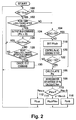
- Fig. 2 there is shown a flow of operation of the controller 26 in the first embodiment of a generator controlling method according to the present invention.
- the controller 26 detects an increase of the battery voltage V B in step 100.
- the voltage V B of the battery 16 increases depending on a charging current and a SOC in the charging operation.
- the battery voltage V B detected by the voltage sensor 30 is compared with a predetermined value V max .
- V max a predetermined value
- step 100 when V B ⁇ V max , or the voltage V B is judged to not have increased so much, the controller 26 discriminates whether SOC ⁇ 70% or not in step 104. As a result in step 104, when it is discriminated that SOC ⁇ 70%, the process moves to step 106.
- step 106 the controller 26 calculates an output P M of the motor 10.
- the motor output P M for example, can be calculated by multiplying the reference torque obtained based on the vehicle signal, by the revolution speed N detected by the rotation speed sensor 28, or it can also be calculated on the basis of the motor voltage V M and motor current I M detected by the respective voltage sensor 36 and current sensor 38.
- the calculated motor output P M is then integrated (or averaged) to obtain an integration (or average) P Mm of the motor outputs P M in step 108 and a decision is made depending on the obtained integration P Mm in step 110.
- step 110 the integration P Mm is compared with predetermined values a and b ( a ⁇ b ) which represent lower and upper limit power values in a target control range of the generator output of the generator 18.
- predetermined values a and b a ⁇ b
- the obtained P G as the reference generator output P Gref is used for controlling the generator 18 (for example, a field control of the generator 18) and the engine 22. Thereafter, the operation returns to step 100.
- the controller 26 also controls the motor output P M depending on the SOC of the battery 16 in step 120. That is, the controller 26 restricts the motor output P M so that the motor output P M may not increase beyond a maximum motor output P Mmax indicated by a solid line in Fig. 3.
- step 122 when the SOC of the battery 16 increases as a result of such controls of the generated power P G and the motor output P M and reaches SOC ⁇ 75%, the operation moves to step 106. In turn, when SOC ⁇ 75% in step 122, the steps 118 to 120 are repeated until the SOC reaches 75%.
- step 102 when it is discriminated that x seconds have not passed, the increase of the voltage V B can be regarded as only a temporary phenomenon and hence the process moves to step 104. On the other hand, when it is discriminated that x seconds have passed in step 102, the increase of the voltage V B is regarded as not the temporary phenomenon and the operation moves to step 124.
- step 124 the controller 26 supplies the idle command to the engine 22 and the generator 18, so that the engine 22 enters the idle state, and the generator 18 stops generation. That is, the generator output P G becomes zero.
- the controller 26 compares the voltage V B of the battery 16 with the predetermined value V max again in step 126. As a result in step 126, when it is discriminated that V B ⁇ V max , i.e., the voltage V B of the battery 16 is still high, the operation returns to step 102. On the contrary, when it is discriminated that V B ⁇ V max in step 126, i.e., the voltage V B of the battery 16 decreases, the operation moves to step 128.
- step 1208 it is discriminated whether or not more than a predetermined number y seconds have passed after the idle command is output.
- step 128 when it is discriminated that y seconds have not passed, the operation returns to step 102.
- step 130 the idle command is canceled and the operation returns to step 100.
- the operation in steps 118 to 122 concerns the SOC control function in this embodiment. That is, when the SOC of the battery 16 drops to less than 70%, the generator output P G is controlled to the predetermined value b , and the motor output P M is restricted based on the curve shown in Fig. 3.
- the predetermined value b in step 118 shows an average consumption power of the motor 10 in a heavy load state which can continuously occur during actual use of the vehicle, for example, an average consumption power when the vehicle is continuously driven at a speed of 100 km/h.
- the operation in step 118 corresponds to controlling of the generator output P G to a relatively large value.
- the restriction of the motor output P M in step 120 that is, the operation for reducing the maximum output P Mmax of the motor 10, as shown in Fig. 3, when the SOC is less than 70%, permits not only a reduction in the amount of the generator output P G which is consumed by the motor 10, but also increases the amount used is change the battery 16.
- the minimum value of the maximum motor output P Mmax is b .
- the operation in steps 106 to 116 corresponds to controlling of the generator output P G depending on the motor output P M .
- the generator output P G is controlled in accordance with the motor output P M calculated on the basis of the reference torque and the revolution speed N or the motor voltage V M and the motor current I M .
- the power consumption of the motor 10 and the generator output P G are nearly coincident with each other, preventing the degradation of the SOC of the battery 16.
- the motor output P M is integrated (or averaged) in step 108, as shown in Fig.
- the motor output P M can be used for the generator control, resulting in the prevention of an emission and fuel consumption drop which are caused by determining the motor output P M to the reference generator output P Gref .
- the generator output P G is limited by the output range a to b of the generator 18 in steps 110 to 116 to obtain the reference generator output P Gref suitable for this output range.
- the motor output P M is multiplied by a factor k resulting from the efficiency of the motor 10 or the inverter 20 in step 114, permitting control considering this efficiency. In this case, it is preferable to determine the integration (average) time constant to approximately 5 seconds in step 108. Further, the value a corresponds to the average consumption power in actual use.
- the operation in steps 100, 102 and 124 to 130 corresponds to the idle control of the engine 22 when the battery voltage V B increases.
- the increase of the voltage V B caused during charging, depending on the charging current I G and the SOC in the rapid regeneration of the motor 10 leads to gassing within the battery 16.
- the voltage increase leads to heat generation. These gassing and heat generation phenomena cause the output change of the engine 22 and also have a detrimental bad effect on the life of the battery 16.
- the idle command is output and the gassing and the heat generation can be prevented.
- the life of the battery 16 can be properly ensured. Since the mutual rapid transition movement between the output state and the idling state on the occasion of outputting or canceling of the idle command induces degradation of fuel consumption and emission, the transitior operation is preferably carried out gradually.
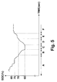
- Fig. 5 illustrates one example of an SOC change of a battery 16 when an SOC control described above, and a generator output P G control on the basis of a motor output P M , are carried out.
- the SOC of the battery 16 is first greater than 80% and is gradually reduced to 70% as the battery is discharged (period A).
- the generator output P G is controlled depending on the motor output P M , and concerning the motor output P M , the restriction as in step 120 is not carried out. It is assumed that from this situation, the battery 16 is further discharged so that the SOC is reduced to 60% (period B).
- steps 118 to 122 are executed via step 104, the generator output P G is controlled to the value b and on the other hand, as shown in Fig. 3, the motor output P M is controlled within the range indicated by the values b to c depending on the SOC.
- the SOC of the battery 16 can be controlled to be close to 70% or at least 60% at the worst, preventing the degradation of the emission and the fuel consumption.
- the control of the generator output P G depending on the motor output P M a similar engine sound to that of an engine vehicle can be obtained and a similar driving feeling to that of a conventional engine vehicle can also be obtained.
- Fig. 6 there is shown a flow of an operation of the controller 26 in the second embodiment of a generator controlling method according to the present invention.
- step 132 is executed in place of steps 106 to 116 in the first embodiment described above.
- the generator output P G is set to the value a and the reference generator output P Gref becomes a value corresponding to the value a .
- the control depending on the motor output P M is not carried out and when considering the situation shown in Fig. 5, a controlling shown in Table 2 is obtained.
- the control of the generator output P G becomes control of a two stage steady state driving of the values a and b and the high efficiency driving of the engine 22 and the generator 18, the reduction of the emission and the like can be attained more noticeably.
- Period generator output P G (kW) motor output P M (kW) A a no limit B b limit to value of range b to c depending on SOC C b b D b limit to value of range b to c depending on SOC E b no limit F a no limit
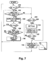
- Fig. 7 there is shown a flow of an operation of the controller 26 in the third embodiment of a generator controlling method according to the present invention.
- step 134 is carried out in place of step 132 in the second embodiment.
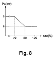
- the generator output P G as the reference generator output P Gref is continuously controlled according to, for example, a map shown in Fig. 8. That is, when the generator output P G is controlled depending on the SOC of the battery 16, two stage control using 70% as a threshold value is not used, but a continuous control, as shown in Fig. 8. Hence, in this embodiment, for instance, while the value of the SOC of the battery 16 is reflected, the generation with an optimum output is performed and the SOC of the battery 16 can be controlled more properly. In this case, although a linear map is shown in Fig. 8, a non-linear map can, of course, be used.
- Fig. 10 there is shown a flow of an operation of the controller 26 in the fourth embodiment of a generator controlling method according to the present invention.
- step 136 is executed in place of steps 108 to 116 in the first embodiment.
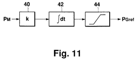
- the reference generator output P Gref is output via a limiter circuit shown in Fig. 11.
- the limiter circuit includes a multiplier 40 for multiplying the motor output P M calculated in step 106 by a predetermined value k, an integrator 42 for integrating the output of the multiplier 40 for a predetermined time (for example, 5 seconds), and a limiter 44 for limiting the output of the integrator 42 on the basis of the output range a to b of the generator 18.
- the output of the limiter 44 as the reference generator output P Gref is supplied to the engine 22 and the generator 18.
- the predetermined value k is determined considering the efficiency of the inverter 20 and the motor 10 in the same manner as the factor k in the first embodiment. Hence, in this embodiment, the same effects as those of the first embodiment can be obtained.
- Fig. 12 there is shown a flow of an operation of the controller 26 in the fifth embodiment of a generator controlling method according to the present invention.
- step 138 is inserted between steps 102 and 124 and step 143 is inserted after step 118 and after step 112, 114 or 116.
- step 138 the generator output P G is controlled so as to be gradually decreased. That is, as shown in Fig. 13, in step 140, a predetermined value ⁇ P G is reduced from the generator output P G and step 140 is repeatedly executed until the obtained generator output P G becomes equal to or less than the value a (P G ⁇ a ) in step 142. At the time point where P G ⁇ a , the operation returns to step 124.
- step 143 as shown in Fig. 14, the generator output P G is controlled to be gradually increased.
- step 146 the generator output P G is substituted with the sum of the generator output P G and the predetermined value ⁇ P G and step 146 is repeatedly executed until the addition result in step 146 becomes more than predetermined value P G0 (P G > P G0 ) in step 148.
- P G > P G0 the generator output P G is substituted with the predetermined value P G0 in step 150 and thereafter the operation returns to step 120 or 100.
- the idle control of the engine 22 and the generation stop control of the generator 18 are carried out in the same manner as the first embodiment and in these controlling steps, the gradual increase or decrease control of the generator output P G is further executed. That is, the reduction in step 140 and the discrimination in step 142 represent the gradual reduction control of the generator output P G or the reference generator output P Gref every predetermined value P G0 and the idle command cannot be output until the time point where the generator output P G becomes small enough (that is, below the value a ).
- step 130 the generator output P G is reiteratively increased by predetermined value ⁇ P G until the generator output P G or reference generator output P Gref reaches the predetermined value P G0 .
- the present invention can be executed in the two states. Further, although the discharge of the battery 16 is also caused by a power supply to electrical appliances on the vehicle (not shown), it can be solved by reflecting as a compensation item in the output restriction of the motor 10 or the generation output control of the generator 18. Moreover, it is preferable to add the limitation to the regeneration amount of the motor 10.
- the generator output is controlled to be increased and the output of the motor is restricted.
- the SOC of the battery can be suitably controlled so as to come within the target range and the life of the battery can be ensured.
- the increase control of the generator output and the output limit of the motor are stopped or avoided and the overcharge of the battery can be prevented.
- the idle control of the engine and the generator stop control are carried out. Hence, the overcharging can be definitely prevented. Moreover, at this time, the generator output is gradually changed and the emission degradation and the fuel consumption deterioration can be prevented.
- the motor output is detected and the generator output is controlled on the basis of the detected output.
- the SOC of the battery can properly be ensured and the fuel consumption degradation of the engine can be prevented.
- the motor output is flattened. Hence, the sharp change of the motor output is not transferred to the generator output and the emission degradation and the fuel consumption deterioration can be prevented more effectively.
- a voltage V B of a battery (16) is compared with a predetermined value V max (100) and when the battery voltage V B is lower than the predetermined value V max as a result of the comparison, a state of charge (SOC) of the battery (16) is discriminated (104).
- SOC state of charge
- an output P G of a generator (18) is controlled on the basis of an output P M of a motor (10) (106 - 116), and in the case of an SOC of less than 70%, while the output P G of the generator (18) is controlled to a relatively high value a , the output P M of the motor (10) is limited (120).
- steps on and after 106 are executed.
- the battery voltage V B is at least the predetermined value V max
- an idle control of an engine (22) is carried out (124). As a result, the SOC of the battery (16) can be ensured and overcharging of the battery (16) can be prevented.
Abstract
Description
- The present invention relates to a controller of a generator mounted on a hybrid vehicle and a control method for this generator.
- As an electric vehicle, a so-called hybrid vehicle is well-known. In the vehicle of this kind, an engine is provided in addition to a motor as a driving source of the vehicle. For example, in a series hybrid vehicle, while an output of a battery such as a lead battery or the like mounted on the vehicle is supplied to the motor as driving power, an output of a generator driven by the engine is also supplied to this motor as the driving power. In this case, the generator and the battery connected in parallel are coupled with the motor and thus the battery can be charged using the output of the generator. That is, even when the battery is discharged during running of the vehicle, it is not necessary to charge this battery using an external power source. In other words, by driving the engine, the battery can be charged using the output of the generator. Moreover, the driving power of the motor can be supplied from not only the battery but also the generator, and the battery can be miniaturized.
- In the case of using the battery such as the lead battery or the like mounted on the hybrid vehicle, by maintaining the state of charge (SOC) of the battery at approximately 70 to 80%, the life of the battery can be sugnificantly extended. Hence, it is preferable to control the SOC of the battery. As the controlling means for the SOC of the battery, for instance, a field current of a generator, that is, a generator output, is controlled to turn on or off, as disclosed in Japanese Patent Laid-Open No.Sho 57-202842.
- However, in such a battery SOC control by controlling the generator output using the on/off control of the field current, it is difficult to accurately control the SOC of the battery in a predetermined range and to prevent overcharging. That is, simple on/off control of the field current often causes the SOC to go out of a target range and also causes overcharging of the battery in certain cases.
- Further, when the motor is under heavy load, the generator output and the power of the battery are used for driving the motor. When this situation lasts for a long period of time, the battery is discharged and its SOC is significantly reduced. This SOC reduction brings about a short battery life.
- Accordingly, it is a first object of the present invention to ensure an elongated battery life.
- It is a second object of the present invention to effectively prevent overcharging of the battery.
- It is a third object of the present invention to improve emission and fuel consumption of an engine.
- It is a fourth object of the present invention to realize a driving feeling similar to a gasoline engine vehicle.
- It is a fifth object of the present invention to attain these objects by controlling an SOC of the battery to be in a predetermined target range even in a continuous heavy load state.
- In accordance with one aspect of the present invention, there is provided a generator controller for controlling an operation of a generator, mounted on a hybrid vehicle including a motor for driving the vehicle; a battery for supplying electric power to the motor; the generator supplying electric power to the motor and the battery; and an engine for driving the generator, the generator controller comprising:
- a) means for detecting a heavy load state in which a battery charge state is reduced to less than a predetermined value;
- b) means for carrying out an increase control of an output of the generator and an output limitation of the motor so that, when the heavy load state is detected, there is a period during which the generator output is used for charging the battery occurs; and
- c) means for either stopping or avoiding the increase control of the generator output and the output limitation of the motor at least when the heavy load state is not detected.
- In accordance with another aspect of the present invention, there is provided a generator controlling method for controlling an operation of a generator, executed on a hybrid vehicle including a battery for supplying electric power to a motor; the generator for supplying electric power to the motor and the battery; and an engine for driving the generator, the generator controlling method comprising:
- a) a step for detecting a heavy load state in which a battery charge state is reduced to less than a predetermined value;
- b) a step for carrying out an increase control of an output of the generator and an output limitation of the motor so that, when the heavy load state is detected, there is a period during which the generator output is used for charging the battery; and
- c) a step for either stopping or avoiding the increase control of the generator output and the output limitation of the motor at least when the heavy load state is not detected.
- In the present invention, first, the heavy load state is detected. When the heavy load state is detected, the increase control of the output of the generator and the output limitation of the motor output are carried out. As a result of this control, there is a period during which the output of the generator is used for the charging of the battery. As a result of this charging, the charge state of the battery is recovered and when the heavy load state is released, the increase control of the generator output and the output limitation of the motor are stopped. Hence, according to the present invention, the SOC of the battery can suitably be ensured and overcharging of the battery can be prevented.
- In the present invention, further, the procedure including step for detecting at least a predetermined degree of charging of the battery as a voltage increased state of at least a predetermined voltage of the battery; a step for carrying out an idle control of the engine and a generation stop control of the generator when the voltage increased state is detected; and a step for either stopping or avoiding the idle control of the engine and the generation stop control of the generator at least when the voltage increased state is not detected, can be executed. At the stage where the idle control of the engine and the generation stop control of the generator are carried out, only the discharge output of the battery is consumed by the motor. As a result of this discharging, after coming from at least the voltage increased state, the idle control of the engine and the generation stop control of the generator are stopped. Hence, in this construction, overcharging of the battery can definitely be prevented.
- In the present invention, moreover, the procedure including a step for gradually decreasing the output of the generator to a predetermined value when the idle control of the engine and the generation stop control of the generator are executed; and a step for gradually increasing the output of the generator to an equivalent value required for the motor output, can be executed. According to this procedure, the degradation of the fuel consumption and emission, upon moving to or stopping the idle control of the engine and the generation stop control of the generator, can be prevented.
- In the present invention, also, the procedure including a step for detecting the output of the motor; and a step for flattening the motor output detected, and controlling the output of the generator on the basis of a value obtained by adding a limitation corresponding to a generation output range of the generator to the flattened motor output, can be performed. According to this procedure, the generator output corresponding to the motor output can be obtained, and hence it becomes difficult to continue discharge of the battery, and its SOC degradation can be prevented. Also, since a flattening of output is carried out, the degradation of the emission and the fuel consumption can be prevented. In addition, in order to obtain the engine output corresponding to the motor output, the control can be executed, and this leads to a realization of a driving feeling similar to that of an engine vehicle due to the engine sound and the like. Further, the motor output is flattened and the control is executed in order to obtain the engine output corresponding to the flattened motor output, thereby carrying out generation depending on an average output of the motor during driving. Hence, a sharp change of the motor output does not appear in the generator output and the generation can be performed with better fuel consumption when the engine is used to for the generator.
- The present invention further includes a step for either stopping or avoiding the idle control of the engine and the generation stop control of the generator only when the voltage increase state continues for a predetermined period of time. In this case, the execution of the idle control of the engine and the generation stop control of the generator regardless of a temporary voltage increase can be prevented.
- In the present invention, also, the idle control of the engine and the generation stop control of the generator are maintained for at least a predetermined time. In this case, the frequency of moving between the idle state and the driving state can be restricted, and hence the degradation of the fuel consumption and the emission with this transition can be prevented.
- In the present invention, the flattening is executed by integrating. This integration can be executed in a software or hardware manner. Also, prior to the flattening, by multiplying the detected motor output by a factor considering efficiency, more precise control can be carried out.
- Further, when the charge state of the battery becomes at least a predetermined value owing to the increase control of the generator output and the output limitation of the motor, in place of the control based on the detected motor output, limitation control of the generator output can be carried out or the generator output can be controlled depending on the charge state of the battery.
- The objects, features and advantages of the present invention will become more apparent from the consideration of the following detailed description, taken in conjunction with the accompanying drawings, in which:
- Fig. 1 is a block diagram of a system of a generator controller of a hybrid vehicle according to the present invention;
- Fig. 2 is a flowchart showing an operation of a first embodiment of a generator controlling method according to the present invention;
- Fig. 3 is a graphical representation showing restriction of a motor output in the first embodiment shown in Fig. 2;
- Fig. 4 is a graphical representation showing control of a generator output depending on the motor output in the first embodiment shown in Fig. 2;
- Fig. 5 is a graphical representation showing one example of an SOC change when carrying out an SOC control in the first embodiment shown in Fig. 2;
- Fig. 6 is a flowchart showing an operation of a second embodiment of a generator controlling method according to the present invention;
- Fig. 7 is a flowchart showing an operation of a third embodiment of a generator controlling method according to the present invention;
- Fig. 8 is a graphical representation showing continuous control of a generator output in the third embodiment shown in Fig. 7;
- Fig. 9 is a graphical representation showing an SOC change when carrying out an SOC control in the third embodiment shown in Fig. 7;
- Fig. 10 is a flowchart showing an operation of a fourth embodiment of a generator controlling method according to the present invention;
- Fig. 11 is a block diagram of an output circuit for a reference generator output in the fourth embodiment shown in Fig. 10;
- Fig. 12 is a flowchart showing an operation of a fifth embodiment of a generator controlling method according to the present invention;
- Fig. 13 is a flowchart showing a gradual decrease of generator output in the fifth embodiment shown in Fig. 12; and
- Fig. 14 is a flowchart showing a gradual increase of the generator output in the fifth embodiment shown in Fig. 12.
- The present invention will now be described in connection with its preferred embodiments with reference to the accompanying drawings, wherein like reference characters designate like or corresponding parts throughout the views and thus the repeated description thereof can be omitted for brevity.
- In Fig. 1, there is shown a system of a generator controller of a hybrid vehicle according to the present invention.
- As shown in Fig. 1, a three-
phase AC motor 10 as a driving source is mounted on the hybrid vehicle. An output axis of themotor 10 is coupled with drivingwheels 14 via adifferential gear unit 12, and thus the vehicle can be driven by driving themotor 10. As a driving source of themotor 10, abattery 16 and agenerator 18 are provided. Thebattery 16 is a lead battery and is connected to the input side of aninverter 20, which converts the output of thebattery 16 into three-phase AC electric power. This power is supplied to themotor 10 to be used for driving. Thegenerator 18 is a three-phase AC generator driven by anengine 22. Theengine 22 is operated in a predetermined high efficiency area with good emission and fuel consumption. The output of thegenerator 18 is rectified by arectifier 24 and the obtained DC current is input to theinverter 20 in the same manner as the output of thebattery 16. Hence, the output of thegenerator 18 is also used as the driving power of themotor 10. The output of thegenerator 18 is also used for charging thebattery 16. - A
controller 26 supplies a PWM (pulse width modulation) signal to theinverter 20 in order to control the output of themotor 10. That is, thecontroller 26 receives a vehicle signal representing the operation of an accelerator, a brake or the like by the driver and calculates a reference torque indicating a torque to be output from themotor 10. In addition, thecontroller 26 also calculates a reference current for themotor 10 using a rotation speed N of themotor 10, detected by arotation speed sensor 28 attached to themotor 10. The obtained reference current is converted into a PWM signal for controlling switching elements which constitute theinverter 20. Since this PWM signal is supplied to theinverter 20, the output of themotor 10 is controlled so as to become an output torque shown by the vehicle signal. - Further, the
controller 26 controls the operations of theengine 22 and thegenerator 18 together with the output torque. In other words, thecontroller 26 controls various driving conditions of theengine 22 and a field current of thegenerator 18 on the basis of a reference generator output PGref obtained by a predetermined calculation. When predetermined conditions are satisfied, thecontroller 26 also gives an idle command to theengine 22 and thegenerator 18, thereby not only controlling theengine 22 to an idle state but stopping the operation of thegenerator 18. - Moreover, in Fig. 1, the
battery 16 is provided with avoltage sensor 30 and anSOC sensor 32. Thesesensors battery 16, respectively, and feed the detected results to thecontroller 26. Acurrent sensor 34 is arranged in a current path between therectifier 24 and thebattery 16 and detects a generated current IG, which is sent to thecontroller 26. Further, avoltage sensor 36 and acurrent sensor 38 are mounted on a wiring coupling between theinverter 20 and themotor 10 and thesesensors controller 26. - In Fig. 2, there is shown a flow of operation of the
controller 26 in the first embodiment of a generator controlling method according to the present invention. - In this embodiment, as shown in Fig. 2, the
controller 26 detects an increase of the battery voltage VB instep 100. The voltage VB of thebattery 16 increases depending on a charging current and a SOC in the charging operation. Instep 100, the battery voltage VB detected by thevoltage sensor 30 is compared with a predetermined value Vmax. As a result, when VB ≧ Vmax instep 100, it is considered that the voltage VB has increased considerably, and steps 102 and subsequent steps will be executed. On the contrary, instep 100, when VB < Vmax, steps 104 and subsequent steps will be carried out. - First, in
step 100, when VB < Vmax, or the voltage VB is judged to not have increased so much, thecontroller 26 discriminates whether SOC ≧ 70% or not instep 104. As a result instep 104, when it is discriminated that SOC ≧ 70%, the process moves to step 106. - In
step 106, thecontroller 26 calculates an output PM of themotor 10. The motor output PM, for example, can be calculated by multiplying the reference torque obtained based on the vehicle signal, by the revolution speed N detected by therotation speed sensor 28, or it can also be calculated on the basis of the motor voltage VM and motor current IM detected by therespective voltage sensor 36 andcurrent sensor 38. The calculated motor output PM is then integrated (or averaged) to obtain an integration (or average) PMm of the motor outputs PM instep 108 and a decision is made depending on the obtained integration PMm instep 110. Instep 110, the integration PMm is compared with predetermined values a and b (a < b) which represent lower and upper limit power values in a target control range of the generator output of thegenerator 18. As a result instep 110, when it is discriminated that PMm < a, a ≦ PMm ≦ b, or PMm > b, the process moves to step 112, 114 or 116, respectively, and a calculation of


step engine 22. Thereafter, the operation returns to step 100. - Then, when the discharge of the
battery 16 continues and it is discriminated that SOC < 70% instep 104, thecontroller 26 sets
generator 18 and outputs this PG as the reference generator output PGref to thegenerator 18 instep 118. Thecontroller 26 also controls the motor output PM depending on the SOC of thebattery 16 instep 120. That is, thecontroller 26 restricts the motor output PM so that the motor output PM may not increase beyond a maximum motor output PMmax indicated by a solid line in Fig. 3. Instep 122, when the SOC of thebattery 16 increases as a result of such controls of the generated power PG and the motor output PM and reaches SOC ≧ 75%, the operation moves to step 106. In turn, when SOC < 75% instep 122, thesteps 118 to 120 are repeated until the SOC reaches 75%. - Next, when it is discriminated that VB ≧ Vmax in
step 100, it is discriminated whether or not more than a predetermined number x seconds have passed after the voltage VB reaches Vmax instep 102. Instep 102, when it is discriminated that x seconds have not passed, the increase of the voltage VB can be regarded as only a temporary phenomenon and hence the process moves to step 104. On the other hand, when it is discriminated that x seconds have passed instep 102, the increase of the voltage VB is regarded as not the temporary phenomenon and the operation moves to step 124. - In
step 124, thecontroller 26 supplies the idle command to theengine 22 and thegenerator 18, so that theengine 22 enters the idle state, and thegenerator 18 stops generation. That is, the generator output PG becomes zero. After executing this control, thecontroller 26 compares the voltage VB of thebattery 16 with the predetermined value Vmax again instep 126. As a result instep 126, when it is discriminated that VB ≧ Vmax, i.e., the voltage VB of thebattery 16 is still high, the operation returns to step 102. On the contrary, when it is discriminated that VB < Vmax instep 126, i.e., the voltage VB of thebattery 16 decreases, the operation moves to step 128. Instep 128, it is discriminated whether or not more than a predetermined number y seconds have passed after the idle command is output. Instep 128, when it is discriminated that y seconds have not passed, the operation returns to step 102. On the other hand, instep 128, when it is discriminated that y seconds have passed, the operation moves to step 130. Instep 130, the idle command is canceled and the operation returns to step 100. - Next, various functions realized by the operation described above will be described.
- First, the operation in
steps 118 to 122, executed depending on the discrimination result instep 104, concerns the SOC control function in this embodiment. That is, when the SOC of thebattery 16 drops to less than 70%, the generator output PG is controlled to the predetermined value b, and the motor output PM is restricted based on the curve shown in Fig. 3. The predetermined value b instep 118 shows an average consumption power of themotor 10 in a heavy load state which can continuously occur during actual use of the vehicle, for example, an average consumption power when the vehicle is continuously driven at a speed of 100 km/h. In other words, the operation instep 118 corresponds to controlling of the generator output PG to a relatively large value. The restriction of the motor output PM instep 120, that is, the operation for reducing the maximum output PMmax of themotor 10, as shown in Fig. 3, when the SOC is less than 70%, permits not only a reduction in the amount of the generator output PG which is consumed by themotor 10, but also increases the amount used is change thebattery 16. The minimum value of the maximum motor output PMmax is b. When such a control is executed, a significant part of the generator output PG is used for the charging of thebattery 16 and as a result, the SOC of thebattery 16 increases. In this embodiment, at the time point where the SOC of thebattery 16 is completely restored instep 122, the compulsory charging insteps step 122, hysteresis relating to the control of the SOC of thebattery 16 can be realized. - Such an SOC control enables suitable control of the SOC of the
battery 16 in the target range, for example, to a range of at least 60%. That is, even if the reduction of the SOC is remarkable, PG becomes equal to PMmax at the time point where SOC = 60% and thus the SOC cannot decrease any further. Also, this is effective in preventing overcharging of thebattery 16. Further, since the generator output PG is controlled to the fixed value b instep 118, theengine 22 and thegenerator 18 are in a steady state during the execution ofsteps - Secondly, the operation in
steps 106 to 116 corresponds to controlling of the generator output PG depending on the motor output PM. This means that the generator output PG is controlled in accordance with the motor output PM calculated on the basis of the reference torque and the revolution speed N or the motor voltage VM and the motor current IM. As a result, the power consumption of themotor 10 and the generator output PG, are nearly coincident with each other, preventing the degradation of the SOC of thebattery 16. Further, in this embodiment, since the motor output PM is integrated (or averaged) instep 108, as shown in Fig. 4, after flattening the acute variations, the motor output PM can be used for the generator control, resulting in the prevention of an emission and fuel consumption drop which are caused by determining the motor output PM to the reference generator output PGref. Moreover, the generator output PG is limited by the output range a to b of thegenerator 18 insteps 110 to 116 to obtain the reference generator output PGref suitable for this output range. Furthermore, the motor output PM is multiplied by a factor k resulting from the efficiency of themotor 10 or theinverter 20 instep 114, permitting control considering this efficiency. In this case, it is preferable to determine the integration (average) time constant to approximately 5 seconds instep 108. Further, the value a corresponds to the average consumption power in actual use. - Thirdly, the operation in
steps engine 22 when the battery voltage VB increases. In particular, in the case of the lead battery used as thebattery 16, the increase of the voltage VB caused during charging, depending on the charging current IG and the SOC in the rapid regeneration of themotor 10, leads to gassing within thebattery 16. Also, in a case of another kind of battery being used, the voltage increase leads to heat generation. These gassing and heat generation phenomena cause the output change of theengine 22 and also have a detrimental bad effect on the life of thebattery 16. In this embodiment, when the battery voltage increase continues for at least x seconds, the idle command is output and the gassing and the heat generation can be prevented. As a result, the life of thebattery 16 can be properly ensured. Since the mutual rapid transition movement between the output state and the idling state on the occasion of outputting or canceling of the idle command induces degradation of fuel consumption and emission, the transitior operation is preferably carried out gradually. - Fig. 5 illustrates one example of an SOC change of a
battery 16 when an SOC control described above, and a generator output PG control on the basis of a motor output PM, are carried out. - As shown in Fig. 5, it is assumed that the SOC of the
battery 16 is first greater than 80% and is gradually reduced to 70% as the battery is discharged (period A). In this period A, sincesteps 106 to 116 are executed, the generator output PG is controlled depending on the motor output PM, and concerning the motor output PM, the restriction as instep 120 is not carried out. It is assumed that from this situation, thebattery 16 is further discharged so that the SOC is reduced to 60% (period B). In this case, sincesteps 118 to 122 are executed viastep 104, the generator output PG is controlled to the value b and on the other hand, as shown in Fig. 3, the motor output PM is controlled within the range indicated by the values b to c depending on the SOC. After the SOC of thebattery 16reaches 60%, as shown in Fig. 3, since the maximum motor output PMmax is set to the value b, the motor output PM is not permitted to exceed the value b. On the other hand, since the generator output PG is controlled to the value b instep 118, thebattery 16 stops discharging period C). That is, the SOC of thebattery 16 does not degrade below 60%. Thereafter, when the charging of thebattery 16 continves due to the difference between the generator output PG and the motor output PM, and the SOC is restoring, until the SOC of thebattery 16reaches 70% (period D), the maximum motor output PMmax of the motor output PM is gradually changed and set from the value b to the value c, and the limit of the motor output PM is gradually released. When the SOC of thebattery 16reaches 70% (period E), the restriction of the motor output PM is removed. Then, when the SOC of thebattery 16 reaches 75% (period F), the limit of the generator output PG is also removed. The SOC change described above is shown in Table 1. - Hence, in this embodiment, by a combination of the SOC control and the generator output PG control depending on the motor output PM, the SOC of the
battery 16 can be controlled to be close to 70% or at least 60% at the worst, preventing the degradation of the emission and the fuel consumption. Moreover, by the control of the generator output PG depending on the motor output PM, a similar engine sound to that of an engine vehicle can be obtained and a similar driving feeling to that of a conventional engine vehicle can also be obtained.TABLE 1 Period generator output PG (kW) motor output PM (kW) A Control depending on PM no limit B b limit to value of range b to c depending on SOC C b b D b limit to value of range b to c depending on SOC E b no limit F Control depending on PM no limit - In Fig. 6, there is shown a flow of an operation of the
controller 26 in the second embodiment of a generator controlling method according to the present invention. - In this embodiment,
step 132 is executed in place ofsteps 106 to 116 in the first embodiment described above. Instep 132, the generator output PG is set to the value a and the reference generator output PGref becomes a value corresponding to the value a. Hence, in this embodiment, differing from the first embodiment, the control depending on the motor output PM is not carried out and when considering the situation shown in Fig. 5, a controlling shown in Table 2 is obtained. - Hence, in this embodiment, the control of the generator output PG becomes control of a two stage steady state driving of the values a and b and the high efficiency driving of the
engine 22 and thegenerator 18, the reduction of the emission and the like can be attained more noticeably.TABLE 2 Period generator output PG (kW) motor output PM (kW) A a no limit B b limit to value of range b to c depending on SOC C b b D b limit to value of range b to c depending on SOC E b no limit F a no limit - In Fig. 7, there is shown a flow of an operation of the
controller 26 in the third embodiment of a generator controlling method according to the present invention. - In this embodiment,
step 134 is carried out in place ofstep 132 in the second embodiment. Instep 134, the generator output PG, as the reference generator output PGref is continuously controlled according to, for example, a map shown in Fig. 8. That is, when the generator output PG is controlled depending on the SOC of thebattery 16, two stage control using 70% as a threshold value is not used, but a continuous control, as shown in Fig. 8. Hence, in this embodiment, for instance, while the value of the SOC of thebattery 16 is reflected, the generation with an optimum output is performed and the SOC of thebattery 16 can be controlled more properly. In this case, although a linear map is shown in Fig. 8, a non-linear map can, of course, be used. Further, in this embodiment, when a situation shown in Fig. 9 is considered, a controlling of the generator output PG and the motor output PM is obtained, as shown in Table 3.TABLE 3 Period generator output PG (kW) motor output PM (kW) A1 a no limit A2 change in range of b to c depending on SOC no limit B b limit to value of range b to c depending on SOC C b b D b limit to value of range b to c depending on SOC E b no limit F change in range of b to c depending on SOC no limit - In Fig. 10, there is shown a flow of an operation of the
controller 26 in the fourth embodiment of a generator controlling method according to the present invention. - In this embodiment,
step 136 is executed in place ofsteps 108 to 116 in the first embodiment. Instep 136, the reference generator output PGref is output via a limiter circuit shown in Fig. 11. - As shown in Fig. 11, the limiter circuit includes a
multiplier 40 for multiplying the motor output PM calculated instep 106 by a predetermined value k, anintegrator 42 for integrating the output of themultiplier 40 for a predetermined time (for example, 5 seconds), and alimiter 44 for limiting the output of theintegrator 42 on the basis of the output range a to b of thegenerator 18. The output of thelimiter 44 as the reference generator output PGref is supplied to theengine 22 and thegenerator 18. Also, the predetermined value k is determined considering the efficiency of theinverter 20 and themotor 10 in the same manner as the factor k in the first embodiment. Hence, in this embodiment, the same effects as those of the first embodiment can be obtained. - In Fig. 12, there is shown a flow of an operation of the
controller 26 in the fifth embodiment of a generator controlling method according to the present invention. - In this embodiment, differing from the first embodiment,
step 138 is inserted betweensteps step 118 and afterstep step 138, as shown in Fig. 13, the generator output PG is controlled so as to be gradually decreased. That is, as shown in Fig. 13, instep 140, a predetermined value ΔPG is reduced from the generator output PG and step 140 is repeatedly executed until the obtained generator output PG becomes equal to or less than the value a (PG ≦ a) instep 142. At the time point where PG ≦ a, the operation returns to step 124. On the other hand, instep 143, as shown in Fig. 14, the generator output PG is controlled to be gradually increased. That is, first, the value of the generator output PG is discriminated to see whether
step 144. As a result of this discrimination, when it is discriminated that
step 146, the generator output PG is substituted with the sum of the generator output PG and the predetermined value ΔPG and step 146 is repeatedly executed until the addition result instep 146 becomes more than predetermined value PG0 (PG > PG0) instep 148. When PG > PG0, the generator output PG is substituted with the predetermined value PG0 instep 150 and thereafter the operation returns to step 120 or 100. - Hence, in this embodiment, the idle control of the
engine 22 and the generation stop control of thegenerator 18 are carried out in the same manner as the first embodiment and in these controlling steps, the gradual increase or decrease control of the generator output PG is further executed. That is, the reduction instep 140 and the discrimination instep 142 represent the gradual reduction control of the generator output PG or the reference generator output PGref every predetermined value PG0 and the idle command cannot be output until the time point where the generator output PG becomes small enough (that is, below the value a). On the other hand, after the idle command is canceled instep 130, as a result of the addition instep 146 and the discrimination instep 148, the generator output PG is reiteratively increased by predetermined value ΔPG until the generator output PG or reference generator output PGref reaches the predetermined value PG0. - These controls prevent the fuel consumption degradation of the
engine 22. That is, when the idle command is output in the state that the generator output PG is relatively large, the generator output PG changes significantly and also there is a fuel consumption degradation due to inertia with the revolution speed increase of theengine 22 on the occasion of increasing the generator output PG again after the idle command is canceled. In this embodiment, this fuel consumption degradation can be prevented. - In the above-described embodiments, whether the
motor 10 is being used for powering or regeneration is not mentioned but the present invention can be executed in the two states. Further, although the discharge of thebattery 16 is also caused by a power supply to electrical appliances on the vehicle (not shown), it can be solved by reflecting as a compensation item in the output restriction of themotor 10 or the generation output control of thegenerator 18. Moreover, it is preferable to add the limitation to the regeneration amount of themotor 10. - As described above, according to the present invention, when the heavy load state is detected, the generator output is controlled to be increased and the output of the motor is restricted. Hence, the SOC of the battery can be suitably controlled so as to come within the target range and the life of the battery can be ensured. Further, when at least the heavy load state is not detected, the increase control of the generator output and the output limit of the motor are stopped or avoided and the overcharge of the battery can be prevented.
- Further, according to the present invention, when the voltage increase state of the battery is detected, the idle control of the engine and the generator stop control are carried out. Hence, the overcharging can be definitely prevented. Moreover, at this time, the generator output is gradually changed and the emission degradation and the fuel consumption deterioration can be prevented.
- According to the present invention, the motor output is detected and the generator output is controlled on the basis of the detected output. Thus, the SOC of the battery can properly be ensured and the fuel consumption degradation of the engine can be prevented. Furthermore, at this time, the motor output is flattened. Hence, the sharp change of the motor output is not transferred to the generator output and the emission degradation and the fuel consumption deterioration can be prevented more effectively.
- Although the present invention has been described in its preferred embodiments with reference to the accompanying drawings, it it readily understood that the present invention is not restricted to the preferred embodiments and that various changes and modifications can be made by those skilled in the art without departing from the spirit and scope of the present invention.
- A voltage VB of a battery (16) is compared with a predetermined value Vmax (100) and when the battery voltage VB is lower than the predetermined value Vmax as a result of the comparison, a state of charge (SOC) of the battery (16) is discriminated (104). In the case of an SOC of at least 70%, an output PG of a generator (18) is controlled on the basis of an output PM of a motor (10) (106 - 116), and in the case of an SOC of less than 70%, while the output PG of the generator (18) is controlled to a relatively high value a, the output PM of the motor (10) is limited (120). When the SOC is restored to more than 75%, steps on and after 106 are executed. When the battery voltage VB is at least the predetermined value Vmax, an idle control of an engine (22) is carried out (124). As a result, the SOC of the battery (16) can be ensured and overcharging of the battery (16) can be prevented.
Claims (12)
- A generator controller (26) for controlling an operation of a generator (18), mounted on a hybrid vehicle, said hydrid vehicle including a motor (10) for driving the vehicle, a battery (16) for supplying electric power to the motor (10); the generator (18) for supplying electric power to the motor (10) and the battery (18); and an engine (22) for driving the generator (18), comprising:
means (104) for detecting a heavy load state in which a battery (16) charge state is reduced to less than a predetermined value;
means (118, 120) for carrying out an increase control of an output of the generator (18) and an output limitation of the motor (10) so that, when the heavy load state is detected, the generator (18) output is used, for a certain period, to charge the battery (16); and
means (104, 122) for either stopping or avoiding the increase control of the generator output and the output limitation of the motor (10) when at least the heavy load state is not detected. - The generator controller of claim 1, further comprising:
means (100) for detecting the battery charge reaching at least a predetermined level as voltage increased condition, which exists when the battery voltage becomes at least a predetermined voltage;
means (124) for carrying out an idle control of the engine (22) and a generation stop control of the generator (18) when the voltage increased condition is detected; and
means (100) for either stopping or avoiding the idle control of the engine (22) and the generation stop control of the generator (18) when at least the voltage increased condition is not detected. - The generator controller of claim 2, further comprising:
means (138) for gradually decreasing the output of the generator (18) to a predetermined value when the idle control of the engine (22) and the generation stop control of the generator (18) are executed; and
means (143) for gradually increasing the output of the generator (18) to an equivalent value required for the motor (10) output. - The generator controller of claim 2, further comprising means (102) for either stopping or avoiding the idle control of the engine (22) and the generation stop control of the generator (18) only when the voltage increase state continues for a predetermined time of period.
- The generator controller of claim 2, wherein the idle control of the engine (22) and the generation stop control of the generator (18) are maintained for at least a predetermined time (128).
- The generator controller of claim 1, further comprising:
means (106) for detecting the output of the motor (10); and
means (108 - 116, 136) for flattening the detected motor output and controlling the output of the generator (18) on the basis of a value obtained by adding a limitation, corresponding to a generation output range of the generator (18), to the flattened motor (10) output. - The generator controller of claim 2, further comprising: means (106) for detecting the output of the motor (10); and
means (108 - 116, 136) for flattening the detected motor output and controlling the output of the generator (18) on the basis of a value obtained by adding a limitation corresponding to a generation output range of the generator (18), to the flattened motor (10) output. - The generator controller of claim 3, further comprising:
means (106) for detecting the output of the motor (10); and
means (108 - 116, 136) for flattening the detected motor output and controlling the output of the generator (18) on the basis of a value obtained by adding a limitation, corresponding to a generation output range of the generator (18), to the flattened motor (10) output. - The generator controller of claim 8, wherein the flattening is executed by integrating.
- The generator controller of claim 8, further comprising means (114, 40) for multiplying the detected motor (10) output by a factor considering efficiency prior to the flattening.
- The generator controller of claim 1, further comprising means (132) for carrying out a limitation control of the output of the generator (18) when the charge state of the battery (16) becomes at least a predetermined value owing to the increase control of the generator output and the output limitation of the motor (10).
- The generator controller of claim 1, further comprising means (134) for controlling the output of the generator (18) depending on the charge state of the battery (16) when the charge state of the battery (16) becomes to at least a predetermined value owing to the increase control of the generator output and the output limitation of the motor (10).
Applications Claiming Priority (2)
| Application Number | Priority Date | Filing Date | Title |
|---|---|---|---|
| JP05237547A JP3094745B2 (en) | 1993-09-24 | 1993-09-24 | Hybrid vehicle power generation control device |
| JP237547/93 | 1993-09-24 |
Publications (2)
| Publication Number | Publication Date |
|---|---|
| EP0645278A1 true EP0645278A1 (en) | 1995-03-29 |
| EP0645278B1 EP0645278B1 (en) | 1999-01-07 |
Family
ID=17016952
Family Applications (1)
| Application Number | Title | Priority Date | Filing Date |
|---|---|---|---|
| EP94114971A Expired - Lifetime EP0645278B1 (en) | 1993-09-24 | 1994-09-22 | Generator controller and controlling method for hybrid vehicle |
Country Status (4)
| Country | Link |
|---|---|
| US (1) | US5550445A (en) |
| EP (1) | EP0645278B1 (en) |
| JP (1) | JP3094745B2 (en) |
| DE (1) | DE69415754T2 (en) |
Cited By (36)
| Publication number | Priority date | Publication date | Assignee | Title |
|---|---|---|---|---|
| EP0743211A2 (en) * | 1995-05-19 | 1996-11-20 | Toyota Jidosha Kabushiki Kaisha | Hybrid vehicle power output apparatus and method of controlling the same at engine idle |
| EP0771687A1 (en) * | 1995-11-06 | 1997-05-07 | Toyota Jidosha Kabushiki Kaisha | Power output apparatus and method of controlling the same |
| EP0782941A1 (en) | 1996-01-05 | 1997-07-09 | SMH Management Services AG | Method and device for control of the electric power distribution in a motor vehicle, especially with hybride drive |
| EP0782940A1 (en) * | 1996-01-05 | 1997-07-09 | SMH Management Services AG | Processing system for a hybrid driven vehicle and control method |
| EP0781680A3 (en) * | 1995-12-27 | 1997-07-23 | Denso Corporation | Power source control apparatus for hybrid vehicles |
| EP0868005A2 (en) * | 1997-03-24 | 1998-09-30 | Toyota Jidosha Kabushiki Kaisha | Power output apparatus and method of controlling the same |
| EP0917982A1 (en) * | 1997-11-21 | 1999-05-26 | Lockheed Martin Corporation | Hybrid electric vehicle with traction motor drive allocated between battery and auxiliary source depending upon battery charge state |
| EP0917981A1 (en) * | 1997-11-21 | 1999-05-26 | Lockheed Martin Corporation | Electric vehicle with variable efficiency regenerative braking depending upon battery charge state |
| US5909094A (en) * | 1995-05-19 | 1999-06-01 | Toyota Jidosha Kabushiki Kaisha | Power output apparatus and method of controlling the same |
| US5988307A (en) * | 1995-05-19 | 1999-11-23 | Toyota Jidosha Kabushiki Kaisha | Power transmission apparatus, four-wheel drive vehicle with power transmission apparatus incorporated therein, method of transmitting power, and method of four-wheel driving |
| EP0903259A3 (en) * | 1997-09-17 | 2000-02-23 | Honda Giken Kogyo Kabushiki Kaisha | Control system for hybrid vehicle |
| GB2346596A (en) * | 1999-02-15 | 2000-08-16 | Automobile Ass Limited The | Operation of a vehicle alternator |
| US6116368A (en) * | 1997-11-21 | 2000-09-12 | Lockheed Martin Corp. | Electric vehicle with battery regeneration dependent on battery charge state |
| EP1127734A2 (en) * | 2000-02-24 | 2001-08-29 | Mitsubishi Jidosha Kogyo Kabushiki Kaisha | Regeneration control device of hybrid electric vehicle |
| WO2001070533A2 (en) * | 2000-03-21 | 2001-09-27 | Nissan Motor Co., Ltd. | Control device for hybrid vehicle |
| EP0773131B1 (en) * | 1995-11-08 | 2001-11-21 | XCELLSIS GmbH | Method for determining the setpoint value of a load for a load-dependent power system within an electric vehicle |
| EP1201486A2 (en) * | 2000-10-27 | 2002-05-02 | Ford Motor Company | Energy control strategy for a hybrid electric vehicle |
| EP1234708A2 (en) * | 2000-10-27 | 2002-08-28 | Ford Motor Company | A hybrid electric vehicle and a control system therefor |
| EP1354746A1 (en) * | 2000-10-31 | 2003-10-22 | Nissan Diesel Motor Co., Ltd. | Hybrid vehicle system |
| FR2841835A1 (en) * | 2002-07-08 | 2004-01-09 | Toyota Motor Co Ltd | VEHICLE CONTROL APPARATUS AND VEHICLE CONTROL METHOD |
| EP1241042A3 (en) * | 2001-03-15 | 2004-01-14 | Nissan Motor Co., Ltd. | Motor-generator control in a hybrid vehicle |
| EP1075976A3 (en) * | 1999-08-10 | 2004-01-21 | Honda Giken Kogyo Kabushiki Kaisha | Apparatus and method for controlling power generation for hybrid vehicle |
| EP1391342A1 (en) * | 2001-03-08 | 2004-02-25 | Aisin Aw Co., Ltd. | Drive controller for hybrid vehicle, control method and program of drive controller for hybrid vehicle |
| EP1302353A3 (en) * | 2001-10-11 | 2004-03-10 | Nissan Motor Co., Ltd. | Control device and control method for hybrid vehicle |
| EP1465315A1 (en) * | 2003-04-04 | 2004-10-06 | Ford Global Technologies, Inc., A subsidiary of Ford Motor Company | Device for supplying electrical energy to a vehicle |
| WO2005002040A1 (en) * | 2003-06-30 | 2005-01-06 | Dometic Sweden Ab | Inverter |
| WO2006064335A1 (en) * | 2004-12-14 | 2006-06-22 | Toyota Jidosha Kabushiki Kaisha | Power output apparatus and vehicle equipped therewith |
| WO2007017043A1 (en) * | 2005-08-10 | 2007-02-15 | Daimler Ag | Drive train for a motor vehicle and method for operating a drive train |
| CN101949160A (en) * | 2009-05-25 | 2011-01-19 | 神钢建设机械株式会社 | Hybrid working machine |
| CN102387932A (en) * | 2009-04-10 | 2012-03-21 | 丰田自动车株式会社 | Automobile and method for controlling said automobile |
| FR2970913A1 (en) * | 2011-02-01 | 2012-08-03 | Sncf | METHOD AND SYSTEM FOR MANAGING THE ENERGY OF A RAIL VEHICLE. |
| EP1902905A3 (en) * | 2006-09-21 | 2013-12-04 | Robert Bosch GmbH | Method and device for stabilising the operating voltage in the electrical system of a motor vehicle |
| RU2501674C1 (en) * | 2012-07-09 | 2013-12-20 | Открытое акционерное общество Научно-исследовательский и конструкторско-технологический институт подвижного состава (ОАО "ВНИКТИ") | Traction motor for transport facility |
| EP2750284A1 (en) * | 2012-12-28 | 2014-07-02 | Denso Corporation | Electric power generation control device and electric power generation control system |
| CN107667032A (en) * | 2015-06-01 | 2018-02-06 | 标致摩托车公司 | Method for the component for controlling battery and alternating current generator of motor vehicle engine |
| CN108859768A (en) * | 2018-07-11 | 2018-11-23 | 阳光电源股份有限公司 | A kind of power system of electric automobile, control method and electric car |
Families Citing this family (94)
| Publication number | Priority date | Publication date | Assignee | Title |
|---|---|---|---|---|
| JP2790779B2 (en) * | 1994-08-22 | 1998-08-27 | 本田技研工業株式会社 | Power generation control device for hybrid vehicle |
| DE4446485C2 (en) * | 1994-12-23 | 2003-06-26 | Daimler Chrysler Ag | Method and device for braking a motor vehicle with hybrid drive |
| JP3505882B2 (en) * | 1995-01-31 | 2004-03-15 | 株式会社デンソー | Power generator for vehicles |
| JP2796698B2 (en) * | 1995-02-02 | 1998-09-10 | 株式会社エクォス・リサーチ | Hybrid vehicle |
| JPH08289407A (en) * | 1995-02-13 | 1996-11-01 | Nippon Soken Inc | Power generation control device for hybrid vehicle |
| KR100316280B1 (en) * | 1995-03-10 | 2002-04-24 | 무라타 기카이 가부시키가이샤 | Step motor control method |
| JP3286492B2 (en) * | 1995-04-28 | 2002-05-27 | 本田技研工業株式会社 | Control device for on-board power generator |
| JPH08331704A (en) * | 1995-05-30 | 1996-12-13 | Honda Motor Co Ltd | Electric propulsion vehicle and its battery output setting method |
| JPH0998515A (en) * | 1995-07-25 | 1997-04-08 | Nippon Soken Inc | Engine controller for hybrid vehicle |
| JP3055439B2 (en) * | 1995-09-28 | 2000-06-26 | 三菱自動車工業株式会社 | Power generation control device for hybrid electric vehicle |
| US5841201A (en) * | 1996-02-29 | 1998-11-24 | Toyota Jidosha Kabushiki Kaisha | Hybrid vehicle drive system having a drive mode using both engine and electric motor |
| CN1055574C (en) * | 1996-03-06 | 2000-08-16 | 杨泰和 | Automatically-monitored and engine-driven assistant accumulator charging system |
| JP3861321B2 (en) * | 1996-05-02 | 2006-12-20 | トヨタ自動車株式会社 | Hybrid car |
| JP3304777B2 (en) * | 1996-08-22 | 2002-07-22 | トヨタ自動車株式会社 | Electric vehicle |
| FR2752778B1 (en) * | 1996-08-27 | 1998-10-09 | Smh Management Services Ag | TANDEM DRIVE UNIT WITH REDUCERS AND ELECTRIC OR HYBRID DRIVE VEHICLE COMPRISING SUCH A GROUP |
| US5994881A (en) * | 1997-10-07 | 1999-11-30 | Hitachi, Ltd. | Control apparatus for a synchronous generator system and a hybrid-type electric vehicle using it |
| US5820172A (en) * | 1997-02-27 | 1998-10-13 | Ford Global Technologies, Inc. | Method for controlling energy flow in a hybrid electric vehicle |
| JP3536581B2 (en) * | 1997-04-16 | 2004-06-14 | 日産自動車株式会社 | Power generation control device for hybrid electric vehicle |
| DE19729382A1 (en) * | 1997-07-10 | 1999-01-14 | Voith Turbo Kg | The electric drive arrangement with a starting torque converter |
| JP3767103B2 (en) * | 1997-07-16 | 2006-04-19 | 日産自動車株式会社 | Electric vehicle control device |
| US6338391B1 (en) | 1999-03-01 | 2002-01-15 | Paice Corporation | Hybrid vehicles incorporating turbochargers |
| US6209672B1 (en) | 1998-09-14 | 2001-04-03 | Paice Corporation | Hybrid vehicle |
| US6554088B2 (en) | 1998-09-14 | 2003-04-29 | Paice Corporation | Hybrid vehicles |
| DE19858697A1 (en) * | 1998-12-18 | 2000-07-27 | Mannesmann Vdo Ag | Method and circuit arrangement for monitoring the operating state of a load |
| DE69936796T2 (en) * | 1999-09-20 | 2008-04-30 | Hitachi, Ltd. | DYNAMOTOR FOR A HYBRID VEHICLE AND METHOD FOR CONTROLLING IT |
| JP3566151B2 (en) * | 1999-10-04 | 2004-09-15 | 本田技研工業株式会社 | Motor control device for hybrid vehicle |
| DE19947922B4 (en) * | 1999-10-06 | 2014-10-30 | Daimler Ag | Device for a commercial vehicle |
| US6274944B1 (en) | 2000-01-06 | 2001-08-14 | Detroit Diesel Corporation | Method for engine control |
| US6242873B1 (en) | 2000-01-31 | 2001-06-05 | Azure Dynamics Inc. | Method and apparatus for adaptive hybrid vehicle control |
| JP2002112406A (en) * | 2000-09-29 | 2002-04-12 | Mitsubishi Motors Corp | Control device for hybrid electric automobile |
| JP3624831B2 (en) | 2000-12-28 | 2005-03-02 | 株式会社デンソー | Vehicle power supply device and engine drive regulation support device |
| US6362602B1 (en) | 2001-05-03 | 2002-03-26 | Ford Global Technologies, Inc. | Strategy to control battery state of charge based on vehicle velocity |
| JP3539406B2 (en) | 2001-06-25 | 2004-07-07 | 日産自動車株式会社 | Hybrid vehicle control device |
| JP4158363B2 (en) * | 2001-08-01 | 2008-10-01 | アイシン・エィ・ダブリュ株式会社 | Hybrid vehicle drive control device |
| JP3607246B2 (en) * | 2001-11-30 | 2005-01-05 | 本田技研工業株式会社 | Control device for hybrid vehicle |
| JP3642319B2 (en) * | 2002-01-30 | 2005-04-27 | トヨタ自動車株式会社 | Control device for vehicle power supply |
| US7042110B2 (en) * | 2003-05-07 | 2006-05-09 | Clipper Windpower Technology, Inc. | Variable speed distributed drive train wind turbine system |
| JP2005018159A (en) * | 2003-06-23 | 2005-01-20 | Fujitsu Ltd | Storage system construction support device, storage system construction support method and storage system construction support program |
| DE10346213A1 (en) * | 2003-10-06 | 2005-04-21 | Bosch Gmbh Robert | Regulating load condition of energy storage device for vehicle with hybrid drive involves regulating state of charge of energy storage device depending on vehicle's speed of travel |
| JP2005138791A (en) * | 2003-11-10 | 2005-06-02 | Nsk Ltd | Steering column device of shock absorbing type |
| ITTO20040054A1 (en) * | 2004-02-04 | 2004-05-04 | Fiat Ricerche | INNOVATIVE ARCHITECTURES OF ENERGY GENERATION AND DISTRIBUTION SYSTEMS ON BOARD MOTOR VEHICLES |
| US7301304B2 (en) * | 2004-02-14 | 2007-11-27 | General Motors Corporation | Energy storage system state of charge diagnostic |
| JP4217192B2 (en) * | 2004-06-01 | 2009-01-28 | 富士重工業株式会社 | Control device for hybrid vehicle |
| KR101119090B1 (en) * | 2004-06-24 | 2012-03-16 | 엘지전자 주식회사 | Apparatus and Method for Preventing Remnant Adhesion of The Dish Washer |
| US20060010844A1 (en) * | 2004-06-30 | 2006-01-19 | Self Guided Systems, L.L.C. | Unmanned utility vehicle |
| US7267191B2 (en) * | 2004-07-30 | 2007-09-11 | Ford Global Technologies, Llc | System and method for battery protection strategy for hybrid electric vehicles |
| US20060030450A1 (en) * | 2004-08-09 | 2006-02-09 | Kyle Ronald L | Hybrid vehicle formed by converting a conventional IC engine powered vehicle and method of such conversion |
| US20100044129A1 (en) * | 2004-08-09 | 2010-02-25 | Hybrid Electric Conversion Co., Llc | Hybrid vehicle formed by converting a conventional ic engine powered vehicle and method of such conversion |
| US20060059880A1 (en) * | 2004-09-13 | 2006-03-23 | Angott Paul G | Unmanned utility vehicle |
| DE102004055128A1 (en) * | 2004-11-16 | 2006-06-01 | Volkswagen Ag | Method for controlling an operation of a hybrid motor vehicle and hybrid vehicle |
| US20070080664A1 (en) * | 2005-07-29 | 2007-04-12 | Ford Global Technologies, Llc | System and method for rebalancing a battery during vehicle operation |
| JP4527047B2 (en) * | 2005-12-02 | 2010-08-18 | パナソニックEvエナジー株式会社 | Secondary battery control device and secondary battery output control method |
| JP4527048B2 (en) * | 2005-12-02 | 2010-08-18 | パナソニックEvエナジー株式会社 | Secondary battery control device and secondary battery input control method |
| JP2007166874A (en) * | 2005-12-16 | 2007-06-28 | Toyota Motor Corp | Voltage converter |
| US7479707B2 (en) * | 2006-02-28 | 2009-01-20 | Deere & Company | Method to optimize alternator load capabilities |
| JP4386451B2 (en) * | 2006-03-06 | 2009-12-16 | 株式会社日立製作所 | Control device for electric vehicle |
| JP2007312469A (en) * | 2006-05-17 | 2007-11-29 | Hitachi Ltd | On-board power supply system, on-board power supply generator, and its control device |
| JP4440232B2 (en) * | 2006-06-06 | 2010-03-24 | 日立建機株式会社 | Electric drive truck drive system |
| JP2007326404A (en) * | 2006-06-06 | 2007-12-20 | Hitachi Constr Mach Co Ltd | Drive system of power-driven dump truck |
| JP4478172B2 (en) * | 2007-05-17 | 2010-06-09 | 本田技研工業株式会社 | Fuel cell vehicle |
| JP4490458B2 (en) * | 2007-06-15 | 2010-06-23 | 日立オートモティブシステムズ株式会社 | Rotating electrical machine control device and vehicle drive device |
| US7825530B2 (en) * | 2007-06-29 | 2010-11-02 | Ise Corporation | Generator voltage stabilization system and method |
| FR2921884A1 (en) * | 2007-10-03 | 2009-04-10 | Peugeot Citroen Automobiles Sa | METHOD FOR CONTROLLING A HYBRID TRACTION CHAIN BASED ON THE BATTERY CHARGE STATE |
| CN101254744B (en) * | 2007-12-28 | 2011-09-21 | 奇瑞汽车股份有限公司 | Hybrid electric vehicle complete vehicle system as well as multi-energy control system and control method thereof |
| US7898219B2 (en) * | 2008-02-25 | 2011-03-01 | Jimmie Doyle Felps | On-board battery supervisor |
| DE102008034461A1 (en) | 2008-07-24 | 2010-01-28 | Ford Global Technologies, LLC, Dearborn | Method and device for determining the operating state of a vehicle battery |
| JPWO2010013314A1 (en) * | 2008-07-29 | 2012-01-05 | 三菱電機株式会社 | Series hybrid vehicle |
| EP2362840A1 (en) * | 2008-09-26 | 2011-09-07 | Arb Greenpower, Llc | Hybrid energy conversion system |
| JP5386935B2 (en) * | 2008-11-05 | 2014-01-15 | 日産自動車株式会社 | Engine start control device for hybrid vehicle |
| EP2308708B1 (en) * | 2009-09-16 | 2016-08-17 | swissauto powersport llc | Electric vehicle with range extension |
| US9187083B2 (en) | 2009-09-16 | 2015-11-17 | Polaris Industries Inc. | System and method for charging an on-board battery of an electric vehicle |
| DE202009015027U1 (en) * | 2009-11-04 | 2010-02-18 | Fischer Panda Gmbh | Device for controlling a vehicle |
| EP2547545B1 (en) * | 2010-01-21 | 2018-12-05 | Epower Engine Systems LLC | Hydrocarbon fueled-electric series hybrid propulsion systems |
| DE112011104613T5 (en) | 2010-12-27 | 2013-12-12 | Honda Motor Co., Ltd. | Generation control device and generation control method |
| RU2013135287A (en) | 2010-12-27 | 2015-02-10 | Хонда Мотор Ко., Лтд. | DEVICE FOR MANAGEMENT OF GENERATION AND METHOD OF MANAGEMENT OF GENERATION |
| JP5332051B2 (en) * | 2011-03-25 | 2013-11-06 | 株式会社小松製作所 | Engine, hydraulic pump and generator motor controller |
| KR20130025822A (en) * | 2011-09-02 | 2013-03-12 | 삼성에스디아이 주식회사 | Apparatus and method for charging a battery of electric device having motor |
| JP6028499B2 (en) * | 2012-04-06 | 2016-11-16 | ソニー株式会社 | Power supply |
| JP5384771B1 (en) * | 2012-07-20 | 2014-01-08 | 三菱電機株式会社 | Control device for hybrid vehicle |
| WO2014073107A1 (en) * | 2012-11-12 | 2014-05-15 | ボルボ ラストバグナー アクチエボラグ | Charge/discharge system |
| JP6195049B2 (en) * | 2013-02-12 | 2017-09-13 | 三菱自動車工業株式会社 | Control device for internal combustion engine |
| JP6171822B2 (en) * | 2013-10-09 | 2017-08-02 | マツダ株式会社 | Control device for hybrid vehicle |
| US9272628B2 (en) * | 2013-12-09 | 2016-03-01 | Textron Inc. | Using AC induction motor as a generator in a utility vehicle |
| US9719477B2 (en) | 2013-12-09 | 2017-08-01 | Textron Inc. | Using a DC or AC generator as a starter with fault detection |
| JP6237583B2 (en) | 2014-11-14 | 2017-11-29 | トヨタ自動車株式会社 | Fuel cell system and air compressor rotation speed control method |
| JP6308111B2 (en) * | 2014-11-21 | 2018-04-11 | トヨタ自動車株式会社 | Vehicle control device |
| US10300786B2 (en) | 2014-12-19 | 2019-05-28 | Polaris Industries Inc. | Utility vehicle |
| US10093166B2 (en) * | 2015-06-08 | 2018-10-09 | Nissan Motor Co., Ltd. | Power generation control system for hybrid vehicle |
| US9816474B2 (en) | 2015-10-20 | 2017-11-14 | Ford Global Technologies, Llc | State of charge based engine start-stop control |
| CA3138437A1 (en) | 2016-06-14 | 2017-12-21 | Polaris Industries Inc. | Hybrid utility vehicle |
| US11807112B2 (en) * | 2016-12-14 | 2023-11-07 | Bendix Commercial Vehicle Systems Llc | Front end motor-generator system and hybrid electric vehicle operating method |
| JP6891974B2 (en) * | 2017-12-15 | 2021-06-18 | 日産自動車株式会社 | Hybrid vehicle control method and hybrid vehicle control device |
| US10780770B2 (en) | 2018-10-05 | 2020-09-22 | Polaris Industries Inc. | Hybrid utility vehicle |
| US11370266B2 (en) | 2019-05-16 | 2022-06-28 | Polaris Industries Inc. | Hybrid utility vehicle |
Citations (5)
| Publication number | Priority date | Publication date | Assignee | Title |
|---|---|---|---|---|
| DE4109379A1 (en) * | 1990-04-04 | 1991-10-10 | Avl Verbrennungskraft Messtech | Vehicle hybrid drive operating control - maintains constant RPM of IC engine at optimum fuel economy and exhaust emission point |
| US5081365A (en) * | 1990-06-06 | 1992-01-14 | Field Bruce F | Electric hybrid vehicle and method of controlling it |
| DE4113386A1 (en) * | 1991-04-24 | 1992-10-29 | Hoehn Bernd Robert Prof Dr Ing | Combined power plant for motor vehicle - has specific fuel consumption, with drive from combustion engine and auxiliary unit, better than with combustion engine alone |
| DE4133013A1 (en) * | 1991-10-04 | 1993-04-08 | Mannesmann Ag | NON-TRACKED VEHICLE WITH ELECTRODYNAMIC CONVERTER |
| EP0543390A1 (en) * | 1991-11-22 | 1993-05-26 | Toyota Jidosha Kabushiki Kaisha | Drive control apparatus of series hybrid vehicle |
Family Cites Families (9)
| Publication number | Priority date | Publication date | Assignee | Title |
|---|---|---|---|---|
| US4199037A (en) * | 1978-05-19 | 1980-04-22 | White Bruce D | Electric automobile |
| US4327295A (en) * | 1980-09-12 | 1982-04-27 | Electro-Kinetics, Inc. | Energy conserving drive system |
| US4413698A (en) * | 1981-01-21 | 1983-11-08 | Conrad Walter W | Battery operated hydraulic vehicle |
| JPS57202842A (en) * | 1981-06-05 | 1982-12-11 | Nissan Motor | Charger for vehicle |
| US4459489A (en) * | 1982-09-30 | 1984-07-10 | General Motors Corporation | Generator load response control |
| JP2932607B2 (en) * | 1990-05-23 | 1999-08-09 | 日産自動車株式会社 | Electric car |
| DE4038225A1 (en) * | 1990-11-30 | 1992-06-04 | Bosch Gmbh Robert | METHOD AND DEVICE FOR VOLTAGE REGULATION DEPENDING ON THE BATTERY CHARGE STATE |
| US5301764A (en) * | 1992-04-13 | 1994-04-12 | Gardner Conrad O | Hybrid motor vehicle having an electric motor and utilizing an internal combustion engine for fast charge during cruise mode off condition |
| US5264764A (en) * | 1992-12-21 | 1993-11-23 | Ford Motor Company | Method for controlling the operation of a range extender for a hybrid electric vehicle |
-
1993
- 1993-09-24 JP JP05237547A patent/JP3094745B2/en not_active Expired - Lifetime
-
1994
- 1994-09-08 US US08/302,412 patent/US5550445A/en not_active Expired - Lifetime
- 1994-09-22 EP EP94114971A patent/EP0645278B1/en not_active Expired - Lifetime
- 1994-09-22 DE DE69415754T patent/DE69415754T2/en not_active Expired - Lifetime
Patent Citations (5)
| Publication number | Priority date | Publication date | Assignee | Title |
|---|---|---|---|---|
| DE4109379A1 (en) * | 1990-04-04 | 1991-10-10 | Avl Verbrennungskraft Messtech | Vehicle hybrid drive operating control - maintains constant RPM of IC engine at optimum fuel economy and exhaust emission point |
| US5081365A (en) * | 1990-06-06 | 1992-01-14 | Field Bruce F | Electric hybrid vehicle and method of controlling it |
| DE4113386A1 (en) * | 1991-04-24 | 1992-10-29 | Hoehn Bernd Robert Prof Dr Ing | Combined power plant for motor vehicle - has specific fuel consumption, with drive from combustion engine and auxiliary unit, better than with combustion engine alone |
| DE4133013A1 (en) * | 1991-10-04 | 1993-04-08 | Mannesmann Ag | NON-TRACKED VEHICLE WITH ELECTRODYNAMIC CONVERTER |
| EP0543390A1 (en) * | 1991-11-22 | 1993-05-26 | Toyota Jidosha Kabushiki Kaisha | Drive control apparatus of series hybrid vehicle |
Cited By (68)
| Publication number | Priority date | Publication date | Assignee | Title |
|---|---|---|---|---|
| US5988307A (en) * | 1995-05-19 | 1999-11-23 | Toyota Jidosha Kabushiki Kaisha | Power transmission apparatus, four-wheel drive vehicle with power transmission apparatus incorporated therein, method of transmitting power, and method of four-wheel driving |
| EP0743211A2 (en) * | 1995-05-19 | 1996-11-20 | Toyota Jidosha Kabushiki Kaisha | Hybrid vehicle power output apparatus and method of controlling the same at engine idle |
| US5909094A (en) * | 1995-05-19 | 1999-06-01 | Toyota Jidosha Kabushiki Kaisha | Power output apparatus and method of controlling the same |
| EP0743211A3 (en) * | 1995-05-19 | 1998-03-18 | Toyota Jidosha Kabushiki Kaisha | Hybrid vehicle power output apparatus and method of controlling the same at engine idle |
| US5791426A (en) * | 1995-11-06 | 1998-08-11 | Toyota Jidosha Kabushiki Kaisha | Power output apparatus and method of controlling the same |
| EP0771687A1 (en) * | 1995-11-06 | 1997-05-07 | Toyota Jidosha Kabushiki Kaisha | Power output apparatus and method of controlling the same |
| EP0773131B1 (en) * | 1995-11-08 | 2001-11-21 | XCELLSIS GmbH | Method for determining the setpoint value of a load for a load-dependent power system within an electric vehicle |
| EP0781680A3 (en) * | 1995-12-27 | 1997-07-23 | Denso Corporation | Power source control apparatus for hybrid vehicles |
| US5789881A (en) * | 1995-12-27 | 1998-08-04 | Denso Corporation | Power source control apparatus for hybrid vehicles |
| US5924505A (en) * | 1996-01-05 | 1999-07-20 | Smh Management Services Ag | Driving system for hybrid-powered motor vehicle and control method for such a system |
| CN1051044C (en) * | 1996-01-05 | 2000-04-05 | Smh管理服务有限公司 | Method and device of controlling electric power distribution for motor vehicles especially the mixing power driven vehicles |
| US5847520A (en) * | 1996-01-05 | 1998-12-08 | Smh Management Services Ag | Method and apparatus for adjusting the electric power distribution in a motor vehicle, in patricular a hybrid-powered vehicle |
| FR2743342A1 (en) * | 1996-01-05 | 1997-07-11 | Smh Management Services Ag | METHOD AND DEVICE FOR ADJUSTING THE DISTRIBUTION OF ELECTRIC POWER IN A MOTOR VEHICLE, IN PARTICULAR HYBRID PROPULSION |
| FR2743343A1 (en) * | 1996-01-05 | 1997-07-11 | Smh Management Services Ag | DRIVE SYSTEM FOR A HYBRID-DRIVEN MOTOR VEHICLE AND ITS DRIVING METHOD |
| EP0782941A1 (en) | 1996-01-05 | 1997-07-09 | SMH Management Services AG | Method and device for control of the electric power distribution in a motor vehicle, especially with hybride drive |
| EP0782940A1 (en) * | 1996-01-05 | 1997-07-09 | SMH Management Services AG | Processing system for a hybrid driven vehicle and control method |
| EP0868005A3 (en) * | 1997-03-24 | 1998-11-11 | Toyota Jidosha Kabushiki Kaisha | Power output apparatus and method of controlling the same |
| EP0868005A2 (en) * | 1997-03-24 | 1998-09-30 | Toyota Jidosha Kabushiki Kaisha | Power output apparatus and method of controlling the same |
| US5936312A (en) * | 1997-03-24 | 1999-08-10 | Toyota Jidosha Kabushiki Kaisha | Power output apparatus and method of controlling the same |
| CN1124208C (en) * | 1997-09-17 | 2003-10-15 | 本田技研工业株式会社 | Control system for hybrid vehicle |
| EP0903259A3 (en) * | 1997-09-17 | 2000-02-23 | Honda Giken Kogyo Kabushiki Kaisha | Control system for hybrid vehicle |
| KR100568727B1 (en) * | 1997-11-21 | 2006-09-20 | 배 시스템즈 컨트롤즈 인코포레이티드 | Method of operating a hybrid electric vehicle with traction motor drive allocated between battery and auxiliary source depending upon battery charge state |
| EP0917981A1 (en) * | 1997-11-21 | 1999-05-26 | Lockheed Martin Corporation | Electric vehicle with variable efficiency regenerative braking depending upon battery charge state |
| US6116368A (en) * | 1997-11-21 | 2000-09-12 | Lockheed Martin Corp. | Electric vehicle with battery regeneration dependent on battery charge state |
| EP0917982A1 (en) * | 1997-11-21 | 1999-05-26 | Lockheed Martin Corporation | Hybrid electric vehicle with traction motor drive allocated between battery and auxiliary source depending upon battery charge state |
| US5941328A (en) * | 1997-11-21 | 1999-08-24 | Lockheed Martin Corporation | Electric vehicle with variable efficiency regenerative braking depending upon battery charge state |
| KR100568728B1 (en) * | 1997-11-21 | 2006-08-23 | 배 시스템즈 컨트롤즈 인코포레이티드 | Method of operating an electric vehicle with variable efficiency regenerative braking depending upon battery charge state |
| GB2346596A (en) * | 1999-02-15 | 2000-08-16 | Automobile Ass Limited The | Operation of a vehicle alternator |
| EP1075976A3 (en) * | 1999-08-10 | 2004-01-21 | Honda Giken Kogyo Kabushiki Kaisha | Apparatus and method for controlling power generation for hybrid vehicle |
| US6429613B2 (en) | 2000-02-24 | 2002-08-06 | Mitsubishi Jidosha Kogyo Kabushiki Kaisha | Generation control device of hybrid electric vehicle |
| EP1127734A3 (en) * | 2000-02-24 | 2002-04-24 | Mitsubishi Jidosha Kogyo Kabushiki Kaisha | Regeneration control device of hybrid electric vehicle |
| EP1127734A2 (en) * | 2000-02-24 | 2001-08-29 | Mitsubishi Jidosha Kogyo Kabushiki Kaisha | Regeneration control device of hybrid electric vehicle |
| WO2001070533A2 (en) * | 2000-03-21 | 2001-09-27 | Nissan Motor Co., Ltd. | Control device for hybrid vehicle |
| WO2001070533A3 (en) * | 2000-03-21 | 2003-04-03 | Nissan Motor | Control device for hybrid vehicle |
| US6659213B2 (en) | 2000-03-21 | 2003-12-09 | Nissan Motor Co., Ltd. | Control device for hybrid vehicle |
| EP1201486A3 (en) * | 2000-10-27 | 2003-11-05 | Ford Motor Company | Energy control strategy for a hybrid electric vehicle |
| EP1234708A3 (en) * | 2000-10-27 | 2003-03-26 | Ford Motor Company | A hybrid electric vehicle and a control system therefor |
| EP1201486A2 (en) * | 2000-10-27 | 2002-05-02 | Ford Motor Company | Energy control strategy for a hybrid electric vehicle |
| EP1234708A2 (en) * | 2000-10-27 | 2002-08-28 | Ford Motor Company | A hybrid electric vehicle and a control system therefor |
| EP1354746A4 (en) * | 2000-10-31 | 2006-03-22 | Nissan Diesel Motor Co | Hybrid vehicle system |
| EP1354746A1 (en) * | 2000-10-31 | 2003-10-22 | Nissan Diesel Motor Co., Ltd. | Hybrid vehicle system |
| EP1391342A1 (en) * | 2001-03-08 | 2004-02-25 | Aisin Aw Co., Ltd. | Drive controller for hybrid vehicle, control method and program of drive controller for hybrid vehicle |
| EP1391342A4 (en) * | 2001-03-08 | 2007-06-13 | Aisin Aw Co | Drive controller for hybrid vehicle, control method and program of drive controller for hybrid vehicle |
| US6819006B2 (en) | 2001-03-15 | 2004-11-16 | Nissan Motor Co., Ltd. | Vehicle control system and vehicle control method |
| EP1241042A3 (en) * | 2001-03-15 | 2004-01-14 | Nissan Motor Co., Ltd. | Motor-generator control in a hybrid vehicle |
| EP1302353A3 (en) * | 2001-10-11 | 2004-03-10 | Nissan Motor Co., Ltd. | Control device and control method for hybrid vehicle |
| US7463958B2 (en) | 2002-07-08 | 2008-12-09 | Toyota Jidosha Kabushiki Kaisha | Vehicle control apparatus and vehicle control method |
| FR2841835A1 (en) * | 2002-07-08 | 2004-01-09 | Toyota Motor Co Ltd | VEHICLE CONTROL APPARATUS AND VEHICLE CONTROL METHOD |
| EP1465315A1 (en) * | 2003-04-04 | 2004-10-06 | Ford Global Technologies, Inc., A subsidiary of Ford Motor Company | Device for supplying electrical energy to a vehicle |
| US7609010B2 (en) | 2003-06-30 | 2009-10-27 | Dometic Sweden Ab | Inverter |
| WO2005002040A1 (en) * | 2003-06-30 | 2005-01-06 | Dometic Sweden Ab | Inverter |
| WO2006064335A1 (en) * | 2004-12-14 | 2006-06-22 | Toyota Jidosha Kabushiki Kaisha | Power output apparatus and vehicle equipped therewith |
| WO2007017043A1 (en) * | 2005-08-10 | 2007-02-15 | Daimler Ag | Drive train for a motor vehicle and method for operating a drive train |
| EP1902905A3 (en) * | 2006-09-21 | 2013-12-04 | Robert Bosch GmbH | Method and device for stabilising the operating voltage in the electrical system of a motor vehicle |
| CN102387932A (en) * | 2009-04-10 | 2012-03-21 | 丰田自动车株式会社 | Automobile and method for controlling said automobile |
| CN102387932B (en) * | 2009-04-10 | 2014-09-17 | 丰田自动车株式会社 | Automobile and method for controlling said automobile |
| CN101949160A (en) * | 2009-05-25 | 2011-01-19 | 神钢建设机械株式会社 | Hybrid working machine |
| CN101949160B (en) * | 2009-05-25 | 2013-09-04 | 神钢建设机械株式会社 | Hybrid working machine |
| FR2970913A1 (en) * | 2011-02-01 | 2012-08-03 | Sncf | METHOD AND SYSTEM FOR MANAGING THE ENERGY OF A RAIL VEHICLE. |
| WO2012104541A3 (en) * | 2011-02-01 | 2013-04-11 | Societe Nationale Des Chemins De Fer Francais Sncf | Method and system for managing the energy of a rail vehicle |
| RU2501674C1 (en) * | 2012-07-09 | 2013-12-20 | Открытое акционерное общество Научно-исследовательский и конструкторско-технологический институт подвижного состава (ОАО "ВНИКТИ") | Traction motor for transport facility |
| EP2750284A1 (en) * | 2012-12-28 | 2014-07-02 | Denso Corporation | Electric power generation control device and electric power generation control system |
| US9184686B2 (en) | 2012-12-28 | 2015-11-10 | Denso Corporation | Electric power generation control device and electric power generation control system |
| CN107667032A (en) * | 2015-06-01 | 2018-02-06 | 标致摩托车公司 | Method for the component for controlling battery and alternating current generator of motor vehicle engine |
| CN107667032B (en) * | 2015-06-01 | 2021-06-01 | 标致摩托车公司 | Method for controlling an assembly of a battery and an alternator for a motor vehicle engine |
| CN108859768A (en) * | 2018-07-11 | 2018-11-23 | 阳光电源股份有限公司 | A kind of power system of electric automobile, control method and electric car |
| CN108859768B (en) * | 2018-07-11 | 2020-08-28 | 阳光电源股份有限公司 | Electric automobile power system, control method and electric automobile |
| US10974600B2 (en) | 2018-07-11 | 2021-04-13 | Sungrow Power Supply Co., Ltd. | Power system of electric vehicle, control method and electric vehicle |
Also Published As
| Publication number | Publication date |
|---|---|
| DE69415754D1 (en) | 1999-02-18 |
| EP0645278B1 (en) | 1999-01-07 |
| JP3094745B2 (en) | 2000-10-03 |
| JPH0795703A (en) | 1995-04-07 |
| DE69415754T2 (en) | 1999-06-17 |
| US5550445A (en) | 1996-08-27 |
Similar Documents
| Publication | Publication Date | Title |
|---|---|---|
| EP0645278A1 (en) | Generator controller and controlling method for hybrid vehicle | |
| US5428274A (en) | Drive control apparatus of series hybrid vehicle | |
| US5945808A (en) | Hybrid electric vehicle with battery management | |
| US8718843B2 (en) | Control method for industrial vehicle and industrial vehicle | |
| US6630810B2 (en) | Hybrid vehicle and control method therefor | |
| EP0647541B1 (en) | Control method for electrical appliance in hybrid vehicle | |
| US5545928A (en) | Electric power generation control method in a hybrid vehicle utilizing detected generator output and engine revolutions | |
| US7533746B2 (en) | Engine control apparatus, control method and control system | |
| KR100361456B1 (en) | Brake control device for electric motor vehicle and its control method | |
| US6727676B2 (en) | Control device for hybrid vehicle | |
| US5635771A (en) | Secondary accumulator charging/discharging for a motor vehicle using a controllable resistor | |
| US5880574A (en) | Control system for electric vehicle | |
| US5600215A (en) | Controller for electric vehicle | |
| US20040018399A1 (en) | Method and system for controlling fuel-cell power for fuel-cell hybrid electric vehicle | |
| US20170047603A1 (en) | Method of controlling fuel cell system, method of controlling fuel cell automobile, and fuel cell automobile | |
| CN110239371B (en) | Fuel cell system, control method, and vehicle provided with fuel cell system | |
| JP3094701B2 (en) | Control device for engine drive generator for electric vehicle | |
| JP3171217B2 (en) | Power supply for motor drive | |
| JPH07236203A (en) | Controller for electric automobile | |
| JP2973657B2 (en) | Power distribution system for series hybrid vehicles | |
| US11485234B2 (en) | Power supply system | |
| JP3200493B2 (en) | Control device for engine drive generator for electric vehicle | |
| JP2019125461A (en) | Fuel cell system | |
| JP3654196B2 (en) | Hybrid electric vehicle | |
| JPH0837702A (en) | Method for controlling power generation of series hybrid vehicle |
Legal Events
| Date | Code | Title | Description |
|---|---|---|---|
| PUAI | Public reference made under article 153(3) epc to a published international application that has entered the european phase |
Free format text: ORIGINAL CODE: 0009012 |
|
| 17P | Request for examination filed |
Effective date: 19940922 |
|
| AK | Designated contracting states |
Kind code of ref document: A1 Designated state(s): DE FR GB |
|
| 17Q | First examination report despatched |
Effective date: 19960710 |
|
| GRAG | Despatch of communication of intention to grant |
Free format text: ORIGINAL CODE: EPIDOS AGRA |
|
| GRAG | Despatch of communication of intention to grant |
Free format text: ORIGINAL CODE: EPIDOS AGRA |
|
| GRAH | Despatch of communication of intention to grant a patent |
Free format text: ORIGINAL CODE: EPIDOS IGRA |
|
| GRAH | Despatch of communication of intention to grant a patent |
Free format text: ORIGINAL CODE: EPIDOS IGRA |
|
| GRAA | (expected) grant |
Free format text: ORIGINAL CODE: 0009210 |
|
| AK | Designated contracting states |
Kind code of ref document: B1 Designated state(s): DE FR GB |
|
| REF | Corresponds to: |
Ref document number: 69415754 Country of ref document: DE Date of ref document: 19990218 |
|
| ET | Fr: translation filed | ||
| PLBE | No opposition filed within time limit |
Free format text: ORIGINAL CODE: 0009261 |
|
| STAA | Information on the status of an ep patent application or granted ep patent |
Free format text: STATUS: NO OPPOSITION FILED WITHIN TIME LIMIT |
|
| 26N | No opposition filed | ||
| REG | Reference to a national code |
Ref country code: GB Ref legal event code: IF02 |
|
| REG | Reference to a national code |
Ref country code: GB Ref legal event code: 746 Effective date: 20130624 |
|
| REG | Reference to a national code |
Ref country code: DE Ref legal event code: R084 Ref document number: 69415754 Country of ref document: DE Effective date: 20130614 |
|
| PGFP | Annual fee paid to national office [announced via postgrant information from national office to epo] |
Ref country code: DE Payment date: 20130918 Year of fee payment: 20 |
|
| PGFP | Annual fee paid to national office [announced via postgrant information from national office to epo] |
Ref country code: FR Payment date: 20130910 Year of fee payment: 20 Ref country code: GB Payment date: 20130918 Year of fee payment: 20 |
|
| REG | Reference to a national code |
Ref country code: DE Ref legal event code: R071 Ref document number: 69415754 Country of ref document: DE |
|
| REG | Reference to a national code |
Ref country code: DE Ref legal event code: R071 Ref document number: 69415754 Country of ref document: DE |
|
| REG | Reference to a national code |
Ref country code: GB Ref legal event code: PE20 Expiry date: 20140921 |
|
| PG25 | Lapsed in a contracting state [announced via postgrant information from national office to epo] |
Ref country code: DE Free format text: LAPSE BECAUSE OF EXPIRATION OF PROTECTION Effective date: 20140923 |
|
| PG25 | Lapsed in a contracting state [announced via postgrant information from national office to epo] |
Ref country code: GB Free format text: LAPSE BECAUSE OF EXPIRATION OF PROTECTION Effective date: 20140921 |