EP0647764A2 - Well treating system with pressure readout at surface - Google Patents
Well treating system with pressure readout at surface Download PDFInfo
- Publication number
- EP0647764A2 EP0647764A2 EP94402221A EP94402221A EP0647764A2 EP 0647764 A2 EP0647764 A2 EP 0647764A2 EP 94402221 A EP94402221 A EP 94402221A EP 94402221 A EP94402221 A EP 94402221A EP 0647764 A2 EP0647764 A2 EP 0647764A2
- Authority
- EP
- European Patent Office
- Prior art keywords
- well
- coiled tubing
- housing
- fluids
- transducer
- Prior art date
- Legal status (The legal status is an assumption and is not a legal conclusion. Google has not performed a legal analysis and makes no representation as to the accuracy of the status listed.)
- Granted
Links
- 238000005259 measurement Methods 0.000 claims abstract description 27
- 239000004020 conductor Substances 0.000 claims abstract description 18
- 238000012545 processing Methods 0.000 claims abstract description 5
- 238000003860 storage Methods 0.000 claims abstract description 3
- 239000012530 fluid Substances 0.000 claims description 58
- 238000002347 injection Methods 0.000 claims description 13
- 239000007924 injection Substances 0.000 claims description 13
- 238000000034 method Methods 0.000 claims description 11
- 230000005540 biological transmission Effects 0.000 claims description 9
- 230000002706 hydrostatic effect Effects 0.000 claims description 4
- 238000005070 sampling Methods 0.000 claims description 4
- 238000012935 Averaging Methods 0.000 claims description 2
- 230000004044 response Effects 0.000 abstract description 5
- 238000004519 manufacturing process Methods 0.000 description 9
- 230000015572 biosynthetic process Effects 0.000 description 6
- 238000004891 communication Methods 0.000 description 6
- 230000004888 barrier function Effects 0.000 description 5
- 230000008901 benefit Effects 0.000 description 4
- 230000007246 mechanism Effects 0.000 description 4
- 230000006870 function Effects 0.000 description 3
- 210000002445 nipple Anatomy 0.000 description 3
- 238000012856 packing Methods 0.000 description 3
- 238000013016 damping Methods 0.000 description 2
- 230000007423 decrease Effects 0.000 description 2
- 238000013461 design Methods 0.000 description 2
- 238000010586 diagram Methods 0.000 description 2
- 229920001971 elastomer Polymers 0.000 description 2
- 239000000806 elastomer Substances 0.000 description 2
- 210000004907 gland Anatomy 0.000 description 2
- 238000012986 modification Methods 0.000 description 2
- 230000004048 modification Effects 0.000 description 2
- BASFCYQUMIYNBI-UHFFFAOYSA-N platinum Chemical compound [Pt] BASFCYQUMIYNBI-UHFFFAOYSA-N 0.000 description 2
- 238000005086 pumping Methods 0.000 description 2
- 239000011435 rock Substances 0.000 description 2
- 238000012360 testing method Methods 0.000 description 2
- 238000004804 winding Methods 0.000 description 2
- 238000004458 analytical method Methods 0.000 description 1
- 230000000712 assembly Effects 0.000 description 1
- 238000000429 assembly Methods 0.000 description 1
- 238000009530 blood pressure measurement Methods 0.000 description 1
- 238000009529 body temperature measurement Methods 0.000 description 1
- 238000010276 construction Methods 0.000 description 1
- 230000005251 gamma ray Effects 0.000 description 1
- 239000007788 liquid Substances 0.000 description 1
- 229910052697 platinum Inorganic materials 0.000 description 1
- 238000003825 pressing Methods 0.000 description 1
- 125000006850 spacer group Chemical group 0.000 description 1
- 239000000126 substance Substances 0.000 description 1
Images


Classifications
-
- E—FIXED CONSTRUCTIONS
- E21—EARTH DRILLING; MINING
- E21B—EARTH DRILLING, e.g. DEEP DRILLING; OBTAINING OIL, GAS, WATER, SOLUBLE OR MELTABLE MATERIALS OR A SLURRY OF MINERALS FROM WELLS
- E21B23/00—Apparatus for displacing, setting, locking, releasing, or removing tools, packers or the like in the boreholes or wells
- E21B23/004—Indexing systems for guiding relative movement between telescoping parts of downhole tools
- E21B23/006—"J-slot" systems, i.e. lug and slot indexing mechanisms
-
- E—FIXED CONSTRUCTIONS
- E21—EARTH DRILLING; MINING
- E21B—EARTH DRILLING, e.g. DEEP DRILLING; OBTAINING OIL, GAS, WATER, SOLUBLE OR MELTABLE MATERIALS OR A SLURRY OF MINERALS FROM WELLS
- E21B33/00—Sealing or packing boreholes or wells
- E21B33/10—Sealing or packing boreholes or wells in the borehole
- E21B33/12—Packers; Plugs
- E21B33/124—Units with longitudinally-spaced plugs for isolating the intermediate space
- E21B33/1243—Units with longitudinally-spaced plugs for isolating the intermediate space with inflatable sleeves
-
- E—FIXED CONSTRUCTIONS
- E21—EARTH DRILLING; MINING
- E21B—EARTH DRILLING, e.g. DEEP DRILLING; OBTAINING OIL, GAS, WATER, SOLUBLE OR MELTABLE MATERIALS OR A SLURRY OF MINERALS FROM WELLS
- E21B47/00—Survey of boreholes or wells
- E21B47/06—Measuring temperature or pressure
-
- E—FIXED CONSTRUCTIONS
- E21—EARTH DRILLING; MINING
- E21B—EARTH DRILLING, e.g. DEEP DRILLING; OBTAINING OIL, GAS, WATER, SOLUBLE OR MELTABLE MATERIALS OR A SLURRY OF MINERALS FROM WELLS
- E21B47/00—Survey of boreholes or wells
- E21B47/12—Means for transmitting measuring-signals or control signals from the well to the surface, or from the surface to the well, e.g. for logging while drilling
Definitions
- This invention relate generally to a new and improved tool string and methods for use in treating an isolated zone in a well, and particularly to a tool string run on coiled tubing and including a sensor package which monitors various pressures and other variables and enables measurements thereof to be read out at the surface in real-time.
- Coiled tubing conveyed tool strings for treating well intervals or zones are known. See for example, U.S. Pat. No. 4,913,231, Muller and Randermann, issued April 3, 1990, which is incorporated herein by express reference.
- the running of tool strings on coiled tubing has the advantage that there are no threaded joints to be made up or broken out, so that the tools can be run much faster and at considerably less expense.
- the 4,913,231 patent also discloses certain valve subsystems for opening and closing various ports and pressure passageways whereby inflatable packers can be expanded and retracted, and treating fluids injected into a zone that is isolated by the packers.
- a general object of the present invention is to provide a new and improved well treating tool string and methods where various downhole measurements of interest can be made and monitored at the surface in real-time.
- Another object of the present invention is to provide a new and improved well treating tool string having inflatable packers to isolate the treatment zone and where packer pressure differentials can be determined at the surface based upon real-time read-out of pressure data.
- a tool string arranged to be run into a well, for example through the production tubing, on the lower end of a length of coiled tubing.
- the tool string includes upper and lower, normally retracted, inflatable packers which are expanded to isolate a well zone in the casing below the production tubing by applying pressure to the inside of the packer elements via the coiled tubing.
- the packer elements are mounted below a selector valve system that performs the necessary valving functions in response to up and down movement of the lower end of the coiled tubing, and a plurality of transducers are mounted inside a tubular body structure located above the selector valve system.
- the transducers are arranged with respect to ports and passages in the body structure to sense internal pressures at the lower end of the coiled tubing, inflation pressures applied to the packers, hydrostatic pressure in the well annulus above the upper packer, treatment fluid injection pressures, and the temperature of fluids in the well bore. Signals which are representative of each of these measures are made available at the surface by a transmission means such as an armored electrical cable which is positioned inside the bore of the coiled tubing prior to winding the same on its reel. The lower end of the armored cable is connected to a transmitter package at the upper end of the transducers, and the upper end of the cable extends out of the upper end of the coiled tubing via a packing gland at the inner portion of the storage reel.
- a transmission means such as an armored electrical cable which is positioned inside the bore of the coiled tubing prior to winding the same on its reel.
- the lower end of the armored cable is connected to a transmitter package at the upper end of the transducers
- the cable is connected to a transmission module and to data processing and display units which make the down-hole measurements of pressure and temperature available at the surface in real time for information, analysis, or interpretation.
- the packer elements are deflated so that they return to their original retracted conditions.
- the tool string is withdrawn from the well through the production tubing as the coiled tubing is wound back onto its reel.
- the signals which are transmitted over the armored cable can be either binary or analog, and other types of transmission methods could be used.
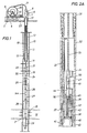
- a well environment in which the present invention typically is used includes a casing 10 that lines a well bore 11 and which has a string of lesser diameter production tubing 12 disposed therein.
- the tubing 12 extends from the surface down to a typical packer 13 which seals off the annulus between the tubing 12 and the casing 10 to confine the pressure in the zone 14 below the packer to the inside of the tubing 12.
- the casing 10 has been perforated at 15 to communicate a producing formation 16 with the bore of the casing so that fluids such as oil or gas can flow upward to the surface via the tubing 12.
- the production tubing 12 is hung off in a tree 17 having side outlets for conveying the produced fluids to a gathering facility (not shown).
- a through-tubing tool string 18 that is constructed in accordance with the present invention is used.
- the use of a through-tubing tool string 18, as noted above, makes it unnecessary to remove or reinstall the production tubing 12, which otherwise would be a time-consuming and expensive procedure.
- the production tubing 12 could be temporarily removed from the well, if desired.
- the tool string 18 is connected to the lower end of coiled tubing 19 which has the tremendous advantage over a standard tubing string having joints threaded end-to-end that no joints need be made up or broken out as the running string 19 is lowered or withdrawn.
- the coiled tubing 19 is wound on a reel 20 at the surface which is mounted on the bed of a truck 23.
- the tubing 19 goes over a guide 9 and into the top of an injector 8 which drives the tubing into and out of the well.
- One or more blowout preventors 7 are provided to ensure complete well control.
- a weight indicator gauge 6 is provided, and fluids under pressure can be pumped into the coiled tubing 19 via a line 5 which leads to the end of the innermost coil of the tubing from a pump 4 which takes fluid from a supply tank 3.
- a depth meter (not shown) also can be provided to inform the operator of the length of the coiled tubing 19 in the well at all times.
- the tool string 18 includes a number of individual components that are connected end-to-end and which cooperate to enable various types of well service jobs to be performed.
- the lower end of the coiled tubing 21 is connected by a typical grapple 21 which can be connected to a check valve assembly 22 which prevents back flow of fluids up the tubing 19.
- the valve assembly 22 is connected to the upper end of a transducer carrier 30 in which a telemetry package and a plurality gauges are mounted.
- One or more accessory tools 24, such as a tubing nipple locator, a casing collar locator, or a gamma ray sensitive tool can be mounted below the carrier 30, and a drag spring valve 25 is located below the tools 24.
- the drag spring valve 25 is connected to the top of a selector valve or packer setting tool 26 which includes a hydraulic delay section 27.
- the lower end of the selector valve 26 suspends upper and lower inflatable packers 28 and 29 which are separated by a spacer nipple 2.
- the tool string 18 can be configured in other ways, the foregoing is exemplary where a well treating operation is to be performed.
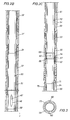
- the telemetry package and transducer carrier assembly 30 is shown in Figures 2A-2D.
- a threaded adapter sub 31 is screwed into the top of an upper tubular housing member 32.
- the upper sub 31 is formed with a depending, generally semi-circular tray 33 having upper and lower circular guide portions 34 and 35.
- the upper nose portion 36 of a hanger sub 37 threads into the bore of the lower guide portion 35, and the lower end of the sub 37 is threaded at 38 to the upper end portion of the housing 40 of a telemetry package indicated generally at 41.
- An insulated electrical lead 42 from the assembly 41 extends up through a central bore 43 in the hanger sub 37 and connects to a male connector member 44 that is seated and sealed in a counterbore 45 in the nose portion 36.
- the connector member 44 has an upstanding pin 47 which engages in the socket 48 of a female connector member 50 which is positioned in the guide 34 as shown.
- the connector member 50 is on the low end of an armored electric monocable 51 which extends up through the coiled tubing 19 to the surface as noted above.
- a single conductor cable 51 having a ground return via the outer armor wires is shown, of course a multi-conductor armored cable can be used. Moreover the return current flow path could be via the coil tubing 19.
- the telemetry package 41 is mounted inside the tubular housing 40, which is threaded at 49 to the upper end of a temperature transducer housing 50 as shown in Figure 2B.
- the outer diameter of the housing 50 is substantially less than the inner diameter of the outer tubular housing member 32' to provide an annular fluid flow passage 51 therebetween.
- the tubular housing members 32 and 32' are threaded to an adapter sub 31' which is located adjacent the connection 49 for ease of assembly.
- the sensing element 46' of the temperature gauge 50 is exposed to fluids in the annular space 51 by ports 46, and thus senses the temperature of fluids flowing through the passage 51 near the lower end of the coiled tubing 19.
- a pressure gauge 52 is threaded at 59 to the lower end of the temperature gauge 50.
- the lower end portion 53 of the carrier housing section 54 is threaded to the upper end of a port sub 55 whose lower end is threaded to the upper end of the next lower carrier housing section 56 therebelow.
- the sub 55 has an inwardly thickened section 57 in which vertical and radial ports 58 and 60 are formed as shown in Figure 3.
- the tubular gauge housing 61 fits snugly in the bore 62 of the sub 55, and seal rings 65 and 66 mounted on the housing 61 are employed to prevent communication between the radial ports 58 and the fluids in the passages 63, 58 and 69.
- the vertical ports 58 allow fluids pumped down the coiled tubing 21 to pass downward through the sub 55 between the annular spaces 63, 64, and the radial ports 60 extend through the walls of the sub 55 to communicate pressures in the well annulus outside the tool string with the pressure sensor element of the gauge 52 via the ports in the housing 61 as shown.
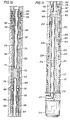
- Another pressure transducer assembly 70 is threaded at 71 to the lower end of the pressure transducer 52 and extends downward within a housing section 72 to where its lower end portion 73 extends into a receiver sub 74 as shown in Figure 2D.
- the sub 74 is threaded to the lower end of the housing section 72 at 75.
- the sub 74 has an integral internal sleeve 76 which forms a pocket 76' in which the lower portion 73 of the gauge 70 is received, there being an arcuate passageway 78 which bypasses such sleeve so that fluids can flow from the annular passageway 64 into the bore region 80 below the lower portion 73.
- the lower end of the receiver sub 74 is threaded at 77 to an adapter sleeve 82 having vertical ports 83 which lead upward to an annular space 84, a radial port 85, and an elongated upwardly extended port 86 which ends in an inwardly directed radial port 87.
- the port 87 communicates with a port 88 in the wall of the sensor section of the pressure transducer 70. Suitable seals 89 and 89' located on the housing 77 above and below the port 88 can be employed to ensure that pressures applied to the sensor port 88 are those in the passages and ports 83-87.
- a mandrel 81 extends up inside the adapter sleeve 82 and the lower end portion of the sub 74 and is sealed with respect to these members as shown.
- the mandrel 81 which is threaded to the sub 74 at 81' forms the upper end portion of a back pressure valve assembly 90 which includes a spring loaded check valve (not shown).
- the details of the valve 90 form no part of the present invention and thus are not shown.
- the annular space 91 between the outer wall surface of the valve assembly 90 and the inner wall surface of the housing section 92 provides a path for fluid pressure to reach the ports 83-87 from a location in the housing 92 below the check valve assembly 90.
- the low end of the housing 92 is attached to an adapter sub 103 which is shown at the top of Figure 4.
- the equalizing-deflate valve assembly 25 whose use in the tool string is optional includes an upper mandrel 101 having whose upper end is secured to an enlarged collar 102 that is threaded to the adapter sub 103.
- the mandrel 101 slides inside a housing 104 which defines an internal annular chamber 105.
- the mandrel 101 carries a stop shoulder 106 that can slide in such chamber between upper and lower positions.
- the stop shoulder 106 is threaded to a lower mandrel 107 which is surrounded by a lower housing 108.
- the housing 108 is connected by threads to the upper end of a tubular valve member 110 having spaced upper and lower internal seals 111, 112 that slidably engage the lower mandrel 107.
- a friction drag assembly which enables circulation ports 113 in the mandrel 107 to be selectively opened and closed includes upper and lower heads 114, 115 which are connected to the ends of resilient bow springs 116 that in their relaxed states have a central diameter that is considerably larger than the inner diameter of the casing 10.
- the lower head 115 is movable relatively along the sleeve 108 so that the springs can retract to positions alongside the housing 100 where the drag tool 25 can pass through the tubing 12. Whether the springs 116 are inside the tubing 12 or the casing 10, they exert friction drag forces which retard longitudinal movement.
- the springs 116 hold the housing 100 in the upper position, as shown, where the circulation ports 113 in the mandrel 107 are open so that the tool string and coiled tubing can fill with fluids standing in the well.
- the springs 116 hold the housing 100 stationary so that the shoulder 106 moves up and engages the shoulder 118.
- the valve sleeve 110 and the seal rings 111, 112 span the ports 113 and closes same to prevent communication between the well annulus and the interior of the tool string.
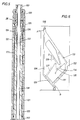
- the lower end of the mandrel 107 of the drag valve tool 25 extends into the upper end portion of the selector-setting tool 26 shown in Figures 5-9.
- the mandrel 107 extends through a sub 120 at the upper end of a tubular housing 121 and is connected at 122 to a mandrel 123 therein.
- a ring 124 which is rotatably mounted between a shoulder 125 and the upper end of the mandrel 123 carries a follower lug 126 which cooperates with a jay-slot system shown in Figure 6 to control the longitudinal relative position of the inner mandrel 123 with respect to the housing 121, which, in turn, controls certain valve functions to be described below.
- the automatic jay-slot tool 26 has a central open bore 139 through which fluids from the coiled tubing can pass when the ports 113 of the drag valve sleeve 110 (Fig. 4) are closed.
- a hydraulic time delay assembly 27 which is shown in Figure 7 forms a lower extension of the jay-slot tool 26.
- the assembly 27 includes a tubular housing 140 and an inner tubular mandrel 141 that are connected as shown to the respective lower ends of the housing 121 and mandrel 123 of the automatic jay mechanism 26.
- the housing 140 has an upper, reduced inner diameter portion 155 that extends downward to a point 159 where the inner diameter thereof is enlarged somewhat to provide a lower enlarged inner diameter portion 154.
- a delay piston assembly 144 is secured to the upper portion of the mandrel 141, and includes a head 145 having a close tolerance fit in the reduced diameter portion 155.
- the head 145 carries a plurality of fluid flow control devices 147, as disclosed in further detail in U.S. Pat. No. 4,913,231.
- the assembly 144 includes a sleeve valve member 146 which is biased toward the head 145 by springs 147 which are mounted on an outwardly directed shoulder 148 on the mandrel 141.
- the valve member 146 carries an upper seal ring 150 that normally is above a lateral port 151 which leads to a longitudinal port 152 in the head 145, and a lower seal ring 153 which engages the wall of the reduced diameter housing section 155.
- the delay assembly 27 is oil-filled in the known manner.
- the force of the springs 147 is overcome and the valve sleeve moves downward to isolate the port 151 and thus the orifice assembly 147.
- the orifice assembly 147 provides two rates of damping because the shifting of the valve sleeve 146 does not affect some of its orifices.
- both sets of orifices are open, the mandrel 141 can move faster relative to the housing 140 in the downward direction, whereas when only one set of orifices is open the mandrel can move only very slowly in the upward direction.
- FIGS. 8-10 illustrate the various operating positions of the selective flow valve mechanism 27 included in the packer setting tool assembly 26.
- the valve mechanism 27 includes a housing member 162 which is connected to the lower end of the delay housing 140 and which receives the lower end portion 163 of the mandrel 160 of the hydraulic delay assembly 144.
- the housing member 162 defines a central bore 164 and a laterally offset, separate packer inflation passage 165.
- the end portion 163 of the mandrel 160 is threaded at 166 to a valve sleeve 167 that has lateral flow ports 168 and carries a seal ring 170 near its lower ends.
- An upstanding flow tube 176 is mounted centrally in the housing 162 and has an upper bore 171 that is open down to a barrier 172, and a lower bore 193 therebelow. Lateral flow ports 173 and 174 are provided respectively above and below the barrier 172.
- the flow tube 176 extends up inside the bore 177 of the valve sleeve 167 and partly up into the lower end of the mandrel 163.
- the tube 176 has additional lateral flow ports 178 which are located opposite the ports 168 in the position of the valve assembly shown in Figure 8.
- a port 180 connects the inflation passage 165 with the ports 168 and 178 and the open bore 171 of the flow tube 176 to enable inflation of the packer elements 28, 29 in the position of parts shown in Figure 8.
- a seal ring 181 prevents leakage between the mandrel 163 and the flow tube 176, and a seal 182 prevents leakage between the valve sleeve 167 and the bore 164 of the housing 162.
- a compensating piston 183 is movable between the housing 162 and the mandrel 163 and carries inside and outside seal rings 184, 185.
- the lower side of the piston 183 is in communication with the well annulus via ports 186.
- the piston 186 can move in order to compensate for changes in volume of hydraulic fluid in the delay section 144 due to downhole changes in temperature and pressure.
- fluids under pressure are pumped into the coiled tubing 19 at the surface which causes flow through the annular passageways 51, 63, and 64 in the instrument housing 32, 54, 56, and thence through the bore of the mandrel 81 and through the open bores of the drag tool 25, the automatic jay mechanism 26, the hydraulic delay 144, and into the bore 171 of the valve tube 176. From there the fluids pass out through the ports 178, 168 and 180 and into the inflation passage 165 which leads to the respective interiors of the inflatable packer elements 28, 29.
- Figure 9 shows the valve assembly 27 with the valve sleeve 167 moved downward along the flow tube 176 to the circulating position in response to lowering of the coiled tubing 19 after the packers 28, 29 have been inflated and set.
- the seal ring 181 now is positioned below the upper radial flow ports 178 and above the radial flow ports 173 which are above the barrier 172. Fluids pumped down the coiled tubing 19 now can pass out of the ports 173, through the annular passage 190, out the ports 168, through the annular passage 191 and out the housing ports 192 into the well annulus.
- Such circulation enables the well fluids in the tubing 19 and tool string 18 to be displaced by a treating fluid until the lower end of the column of such fluid is adjacent the packers 28 and 29.
- Annulus pressures are sensed by the transducer inside the housing 61 via the ports 60 at all times.
- Figure 10 shows the relative position of the selector valve parts when treating fluids are being injected into the interval that is isolated by the packers 28, 29.
- the valve sleeves 163 and 167 have been lowered further until the seal ring 181 is below both the barrier 172 and the lower radial ports 174.
- the circulating ports 192 are closed off from communication with the lower bore 193 of the flow tube 176 by the seal rings 181 and 170 (Fig. 8).
- Treating fluids now can be pumped down the tubing 19 flow past the barrier 172 via the annular space 194, and then through the ports 174 and into the bore 193. From there the fluids flow down through the body of the upper packer 28 and out the injection ports 213 into the isolated zone.
- the lower end of the flow tube 176 is mounted by a fixture 195 in a lower portion 196 of the housing member 162.
- a seal ring 197 prevents fluid leakage.
- An internal chamber 198 in the housing portion 196 receives a connector head 200 at the upper end of the body member 201 which mounts the packer assemblies 28, 29.
- the head 200 defines an injection passage 212 and an inflation passage 202.
- the passage 202 communicates with a radial port 203 which leads to the inflation passage 165 via port 204. Seals 205 and 206 prevent leakage.
- the lower end of the housing 162 is provided with a collar 207 which can be secured to the connector head 200 by tangential shear pins 208 or the like to provide a releasable connection in the event the packers 28, 29 should get stuck in the well bore.
- the upper end of the connector head 208 provides a fishing neck for that purpose.
- the lower packer element 29 is identical to the upper packer 28 and also is not shown.
- the inflation passage 202 leads to a port 210 that communicates with the interior of an elastomer sleeve-like structure 211 whose upper end is fixed and sealed against the body member 201.
- the lower end of the sleeve structure 212 also is sealed against the body member 201, but can be arranged to move upward as the structure expands.
- the inflation passage 202 also leads down to a port which communicates fluid under pressure to the lower packer element 29 ( Figure 1).
- the injection passageway 212 extends down in the body member 201 to one or more side ports 213 through which treating fluids are injected into the well interval that is isolated by the packers.
- a separate equalizing passage 213 which extends from below the lower packer 29 up through the body member 201 to a port 214 located above the upper packer element 28 functions to communicate the pressure of fluids below the lower packer 29 with those in the annulus above the upper packer 28 at all times.
- the surface equipment comprises a telemetry module 250 having an amplifier and signal conditioner 251, a universal asynchronous receiver/transmitter (UART) 252 and a telemetry interface 249.
- the balance of the surface components includes a central processing unit (CPU) 253 and a display 254.
- This system employs a baseband telemetry technique where binary encoded commercial and data packets with error checking are used to communicate with the downhole telemetry sub 41 via the armored electric cable 51 and to obtain surface readouts of the measurements made by the temperature transducer sub 50 and the pressure transducer subs 52 and 70.
- the downhole measurement and telemetry components which receive line power and signals via the armored cable 51 include a power supply 256 and a switcher 257 in the telemetry sub 41.
- the switcher 257 is connected to a telemetry interface 258, a signal conditioner 260 and a temperature sensor 261 housed in the sub 50.
- the sensor 261 can be a platinum thermocouple or the like.
- the pressure reading sub 52 also includes a telemetry interface 263, a signal conditioner 264, and a pressure sensor 265 which can be, for example, a strain gauge mounted on an atmospheric chamber wall that is deformed in proportion to pressure differential.
- the pressure measuring sub 70 iii cludes essentially the same components as the sub 52, namely a telemetry interface 267, a signal conditioner 268 and a strain gauge pressure transducer 270.
- the subs 52 and 70 enable the measurement of a combination of outside and inside pressures as well as packer inflation pressures.
- the string tool 18 is assembled as shown in the drawings and run into the well through the production tubing 12 on the lower end of the coiled tubing 19.
- the electrical conductor cable 51 will have been positioned inside the coiled tubing 21 prior to the time it was wound on the reel 20.
- the cable 51 can be an armored monocable (single center conductor) or an armored multiconductor cable, as desired.
- the waterproof connector 50 is terminated on the outer end of the cable 51, and is connected to the companion male connector 47 at the upper end of the conductor 42 which connects to the telemetry sub 140.
- the upper end of the cable 51 is brought out through a packing gland on the outer end of the coiled tubing, and leads to the telemetry module 250 at the surface.
- the transducer 52 measures annulus pressure above the upper packer element 28, which will be approximately the same as the pressure below the lower packer 29 on account of the equalizing passage 214, and the other pressure transducer measures pressures inside the tool string 10, which reflect inflation pressures during packer setting, as well as injection pressures during the treating operation.
- the transducer 50 measures the temperature of fluids inside the tool string 18 which is useful in calculating packer and injection pressures.
- the tool string 18 is halted a few feet below such depth, and then raised back upward about the same distance. This causes the drag mandrel 101, 107 to move upward relative to the springs 116 and the valve sleeve 110 which closes off the ports 113. Fluid then is pumped down the coiled tubing 19 and through the various inflation passages and ports including 178, 168, 180, 165, 203, 202 and 210 and into the interior of each inflatable packer element 28, 29. As such pressure is increased, the elastomer packer elements 211 expand outward until their outer peripheries sealingly engage the surrounding walls of the casing 10 to pack off the upper and lower ends of the treatment zone.
- the transducers 52 and 70 together with the telemetry cartridge 40, the conductor cable 51 and the surface components 250, 253 and 254 provide real time read-outs at the surface of the hydrostatic pressure in the annulus, the inflation pressures applied to the packers 28, 29 and the treating fluid pressure applied to the isolated zone via the ports and passages 173, 190, 174, 193, 212 and 213. Pressures inside the tool string involved in circulating through the port 192 to spot treating fluids also can be read out at the surface.
- the transducer 50 provides a surface reading ot downhole temperature which is useful in connection with packer setting pressure determinations.
- the operator can cause the traction system 8 at the surface to pull upward on the coil tubing 19, which should result in an increase in the reading of the weight indicator gauge 6.
- the coiled tubing 19 is lowered so that the selector valve mandrel 163, 167 moves downward within housing 12 as shown in Figure 9 as the follower lug 126 on the ring 124 moves into the lower pocket "B".
- the inflate/deflate passages continue to be closed off so that inflation pressures are trapped within the packers 28, 19.
- This position also communicates the coiled tubing 19 with the isolated zone via the injection ports 213 and the ports and passages 194, 174, 193 and 212, so that pressure can be applied to the formation 16 to determine if it will accept fluids, and at what pressures.
- the inside pressure sensitive transducers 70 make measurements which are transmitted to the surface so that they can be read out in real time.
- treating fluid is spotted as follows.
- the traction device 8 is operated to raise the valve mandrel 165 relative to its housing 162. Initially, there is an amount of free travel that occurs as the piston head 146 in the damper assembly 144 moves up the enlarged diameter lower cylinder portion 154. However when the piston assembly 146 enters the reduced diameter cylinder portion 155, restricted flow retards upward movement so that several minutes are required for the damper assembly 144 to become fully extended as shown in Figure 7.
- the resistance to further upward movement of the tubing 19 provides a surface indication of the sequence of operation.
- the follower lug 126 moves up the channel to the position "D".
- the operator increases the tension on the tubing 19 to raise the follow lug 126 out of the pocket "C" until it moves past the position indicated at "D” in Figure 6. Such tension is not maintained for more than about two minutes to ensure that the valve 27 does not move back to the inflate/deflate position.
- the tubing 19 then is lowered to cause the follower lug 126 to move down along the channel surfaces 137 and 129 and back to the lower pocket "B". This relative movement positions the valve 27 for injection, and a weight indication that is less than run-in weight confirms that the packers 28 and 29 are still set.
- the spotted treatment fluid then is pumped down the tool passages and injected via ports 213 into the isolated zone between the packers 28, 29 where it enters the formation 16 through the perforations 15. Injection pressures are monitored continuously by the inside-reading gauge 70 and transmitted to the surface as described above.
- the surface pump 4 is shut down and the traction unit 8 is operated to cause the follower lug 126 to move up along the channel 131, Figure 6.
- the dampener piston 146 moves into active position, tension is maintained on the tubing 19 for more than about three minutes, so that the follower lug 146 moves all the way back to the upper pocket "A", at which point the inflate/deflate passage 165 is opened. This enables the packers 28, 29 to deflate and inherently retract, which can be confirmed by observing a decrease in weight indicator reading at the surface.
- the telemetry system 250 at the surface samples each of the downhole transducers every 100 milliseconds, for example, during normal operation. Sampling rates may differ during initialization.
- the data signals received from the downhole transducers 50, 52 and 70 are stored in memory by the CPU 253.
- the surface electronics performs averaging and noise rejection before passing the data on to other recording equipment and the interference module 249.
- the module 254 is the display unit that plots the data for the operator to observe for trends in the downhole measurements.
- the packers are deflated so that the tool string 18 can be moved to another location in the casing 10 where another operation is to be performed, or the tool string can be removed from the well by winding the tubing 19 back onto the reel 20.
- a read-out of pressures and temperature is available in real-time at the surface. From such readings the inflatable packer pressure differentials can be determined, and operational adjustment can be made at the surface to maintain such differentials within design limits. The response of the formation rock to the treatment can be monitored which allows real-time adjustment of treatment pressures to optimize the results.
Abstract
Description
- This invention relate generally to a new and improved tool string and methods for use in treating an isolated zone in a well, and particularly to a tool string run on coiled tubing and including a sensor package which monitors various pressures and other variables and enables measurements thereof to be read out at the surface in real-time.
- Coiled tubing conveyed tool strings for treating well intervals or zones are known. See for example, U.S. Pat. No. 4,913,231, Muller and Randermann, issued April 3, 1990, which is incorporated herein by express reference. The running of tool strings on coiled tubing has the advantage that there are no threaded joints to be made up or broken out, so that the tools can be run much faster and at considerably less expense. The 4,913,231 patent also discloses certain valve subsystems for opening and closing various ports and pressure passageways whereby inflatable packers can be expanded and retracted, and treating fluids injected into a zone that is isolated by the packers. Although such systems and subsystems represent considerable advances in the art, it would be highly useful and advantageous to have real-time surface read out of the values of certain downhole pressures, such as the pressure inside the coil tubing, hydrostatic pressure, packer inflation pressures, injection pressures, as well as other data such as downhole temperatures and the like. These measurements are significant because changing downhole well conditions during a treatment operation, which are not otherwise known at the surface without extensive calculations and assumptions, can cause unexpected failure of inflatable packers and/or tool operations. Of particular interest are inflatable packer pressure differentials to allow adjustments to be made at the surface which will maintain such differentials within design limits. Another variable of significance is the response of the reservoir rock to the treatment, which can be monitored if the pressure in the isolated zone is known so that the treatment can be adjusted to achieve optimum results. Other advantages for surface read-out of pressure as well as other variables will be apparent.
- A general object of the present invention is to provide a new and improved well treating tool string and methods where various downhole measurements of interest can be made and monitored at the surface in real-time.
- Another object of the present invention is to provide a new and improved well treating tool string having inflatable packers to isolate the treatment zone and where packer pressure differentials can be determined at the surface based upon real-time read-out of pressure data.
- These as well as other objects are attained in accordance with the present invention through the provision of a tool string arranged to be run into a well, for example through the production tubing, on the lower end of a length of coiled tubing. The tool string includes upper and lower, normally retracted, inflatable packers which are expanded to isolate a well zone in the casing below the production tubing by applying pressure to the inside of the packer elements via the coiled tubing. The packer elements are mounted below a selector valve system that performs the necessary valving functions in response to up and down movement of the lower end of the coiled tubing, and a plurality of transducers are mounted inside a tubular body structure located above the selector valve system. The transducers are arranged with respect to ports and passages in the body structure to sense internal pressures at the lower end of the coiled tubing, inflation pressures applied to the packers, hydrostatic pressure in the well annulus above the upper packer, treatment fluid injection pressures, and the temperature of fluids in the well bore. Signals which are representative of each of these measures are made available at the surface by a transmission means such as an armored electrical cable which is positioned inside the bore of the coiled tubing prior to winding the same on its reel. The lower end of the armored cable is connected to a transmitter package at the upper end of the transducers, and the upper end of the cable extends out of the upper end of the coiled tubing via a packing gland at the inner portion of the storage reel. From there the cable is connected to a transmission module and to data processing and display units which make the down-hole measurements of pressure and temperature available at the surface in real time for information, analysis, or interpretation. When the treatment operation is completed, the packer elements are deflated so that they return to their original retracted conditions. Then the tool string is withdrawn from the well through the production tubing as the coiled tubing is wound back onto its reel. The signals which are transmitted over the armored cable can be either binary or analog, and other types of transmission methods could be used.
- The present invention has the above as well as other objects, features and advantages which will become more clearly apparent in connection with the following detailed description of a preferred embodiment in which:
- Figure 1 is a schematic view of a well treating operation using a tool string that is run on coiled tubing;
- Figures 2A-C are longitudinal sectional views, with some parts in side elevation, of the telemetry and sensor package of the present invention;
- Figure 3 is a cross-section on line 3-3 of Figure 2B;
- Figure 4 is a longitudinal sectional view of the deflate/drag spring valve;
- Figure 5 is a longitudinal sectional view of the indexing portion of the selector valve assembly;
- Figure 6 is a developed plan view of the automatic jay-slot used in the valve assembly of Figure 5;
- Figure 7 is a longitudinal sectional view of the hydraulic delay portion of the assembly shown in Figure 5;
- Figures 8-10 are sectional views showing various operating positions of the selector valve assembly;
- Figure 11 is a sectional view of the packer section of the tool string; and
- Figure 12 is a schematic block diagram of the transducers, telemetry and other related components of the present invention.
- Referring initially to Figure 1, a well environment in which the present invention typically is used includes a
casing 10 that lines a well bore 11 and which has a string of lesserdiameter production tubing 12 disposed therein. Thetubing 12 extends from the surface down to atypical packer 13 which seals off the annulus between thetubing 12 and thecasing 10 to confine the pressure in thezone 14 below the packer to the inside of thetubing 12. Thecasing 10 has been perforated at 15 to communicate a producingformation 16 with the bore of the casing so that fluids such as oil or gas can flow upward to the surface via thetubing 12. At the surface theproduction tubing 12 is hung off in atree 17 having side outlets for conveying the produced fluids to a gathering facility (not shown). - In order to perform a well treating or other service operation in the
well casing 10 below thepacker 13 in a manner such that downhole pressures, temperatures and other variables are immediately available at the surface, a through-tubing tool string 18 that is constructed in accordance with the present invention is used. The use of a through-tubing tool string 18, as noted above, makes it unnecessary to remove or reinstall theproduction tubing 12, which otherwise would be a time-consuming and expensive procedure. However theproduction tubing 12 could be temporarily removed from the well, if desired. Thetool string 18 is connected to the lower end of coiledtubing 19 which has the tremendous advantage over a standard tubing string having joints threaded end-to-end that no joints need be made up or broken out as the runningstring 19 is lowered or withdrawn. The coiledtubing 19 is wound on areel 20 at the surface which is mounted on the bed of atruck 23. Thetubing 19 goes over a guide 9 and into the top of aninjector 8 which drives the tubing into and out of the well. One ormore blowout preventors 7 are provided to ensure complete well control. Aweight indicator gauge 6 is provided, and fluids under pressure can be pumped into thecoiled tubing 19 via aline 5 which leads to the end of the innermost coil of the tubing from apump 4 which takes fluid from asupply tank 3. A depth meter (not shown) also can be provided to inform the operator of the length of the coiledtubing 19 in the well at all times. - The
tool string 18 includes a number of individual components that are connected end-to-end and which cooperate to enable various types of well service jobs to be performed. The lower end of the coiledtubing 21 is connected by atypical grapple 21 which can be connected to acheck valve assembly 22 which prevents back flow of fluids up thetubing 19. Thevalve assembly 22 is connected to the upper end of atransducer carrier 30 in which a telemetry package and a plurality gauges are mounted. One ormore accessory tools 24, such as a tubing nipple locator, a casing collar locator, or a gamma ray sensitive tool can be mounted below thecarrier 30, and adrag spring valve 25 is located below thetools 24. Thedrag spring valve 25 is connected to the top of a selector valve orpacker setting tool 26 which includes ahydraulic delay section 27. The lower end of theselector valve 26 suspends upper and lowerinflatable packers spacer nipple 2. Although thetool string 18 can be configured in other ways, the foregoing is exemplary where a well treating operation is to be performed. - The telemetry package and
transducer carrier assembly 30 is shown in Figures 2A-2D. A threadedadapter sub 31 is screwed into the top of an uppertubular housing member 32. Theupper sub 31 is formed with a depending, generally semi-circular tray 33 having upper and lowercircular guide portions upper nose portion 36 of ahanger sub 37 threads into the bore of thelower guide portion 35, and the lower end of thesub 37 is threaded at 38 to the upper end portion of thehousing 40 of a telemetry package indicated generally at 41. An insulatedelectrical lead 42 from theassembly 41 extends up through acentral bore 43 in thehanger sub 37 and connects to amale connector member 44 that is seated and sealed in acounterbore 45 in thenose portion 36. Various additional seals, as shown, prevent fluid leakage into thetelemetry package 41. Theconnector member 44 has anupstanding pin 47 which engages in thesocket 48 of afemale connector member 50 which is positioned in theguide 34 as shown. Theconnector member 50 is on the low end of an armoredelectric monocable 51 which extends up through the coiledtubing 19 to the surface as noted above. Although asingle conductor cable 51 having a ground return via the outer armor wires is shown, of course a multi-conductor armored cable can be used. Moreover the return current flow path could be via thecoil tubing 19. - The
telemetry package 41 is mounted inside thetubular housing 40, which is threaded at 49 to the upper end of atemperature transducer housing 50 as shown in Figure 2B. The outer diameter of thehousing 50 is substantially less than the inner diameter of the outer tubular housing member 32' to provide an annularfluid flow passage 51 therebetween. Thetubular housing members 32 and 32' are threaded to an adapter sub 31' which is located adjacent the connection 49 for ease of assembly. The sensing element 46' of thetemperature gauge 50 is exposed to fluids in theannular space 51 byports 46, and thus senses the temperature of fluids flowing through thepassage 51 near the lower end of the coiledtubing 19. Apressure gauge 52 is threaded at 59 to the lower end of thetemperature gauge 50. As shown in Figure 2C, thelower end portion 53 of thecarrier housing section 54 is threaded to the upper end of aport sub 55 whose lower end is threaded to the upper end of the next lowercarrier housing section 56 therebelow. Thesub 55 has an inwardly thickenedsection 57 in which vertical andradial ports tubular gauge housing 61 fits snugly in thebore 62 of thesub 55, and seal rings 65 and 66 mounted on thehousing 61 are employed to prevent communication between theradial ports 58 and the fluids in thepassages vertical ports 58 allow fluids pumped down the coiledtubing 21 to pass downward through thesub 55 between theannular spaces radial ports 60 extend through the walls of thesub 55 to communicate pressures in the well annulus outside the tool string with the pressure sensor element of thegauge 52 via the ports in thehousing 61 as shown. - Another
pressure transducer assembly 70 is threaded at 71 to the lower end of thepressure transducer 52 and extends downward within ahousing section 72 to where itslower end portion 73 extends into areceiver sub 74 as shown in Figure 2D. Thesub 74 is threaded to the lower end of thehousing section 72 at 75. Thesub 74 has an integralinternal sleeve 76 which forms a pocket 76' in which thelower portion 73 of thegauge 70 is received, there being anarcuate passageway 78 which bypasses such sleeve so that fluids can flow from theannular passageway 64 into thebore region 80 below thelower portion 73. The lower end of thereceiver sub 74 is threaded at 77 to anadapter sleeve 82 havingvertical ports 83 which lead upward to anannular space 84, aradial port 85, and an elongated upwardly extended port 86 which ends in an inwardly directedradial port 87. Theport 87 communicates with a port 88 in the wall of the sensor section of thepressure transducer 70.Suitable seals 89 and 89' located on thehousing 77 above and below the port 88 can be employed to ensure that pressures applied to the sensor port 88 are those in the passages and ports 83-87. - A
mandrel 81 extends up inside theadapter sleeve 82 and the lower end portion of thesub 74 and is sealed with respect to these members as shown. Themandrel 81 which is threaded to thesub 74 at 81' forms the upper end portion of a backpressure valve assembly 90 which includes a spring loaded check valve (not shown). The details of thevalve 90 form no part of the present invention and thus are not shown. Theannular space 91 between the outer wall surface of thevalve assembly 90 and the inner wall surface of thehousing section 92 provides a path for fluid pressure to reach the ports 83-87 from a location in thehousing 92 below thecheck valve assembly 90. The low end of thehousing 92 is attached to anadapter sub 103 which is shown at the top of Figure 4. - Referring now to Figure 4, the equalizing-
deflate valve assembly 25 whose use in the tool string is optional includes anupper mandrel 101 having whose upper end is secured to anenlarged collar 102 that is threaded to theadapter sub 103. Themandrel 101 slides inside ahousing 104 which defines an internalannular chamber 105. Themandrel 101 carries astop shoulder 106 that can slide in such chamber between upper and lower positions. Thestop shoulder 106 is threaded to alower mandrel 107 which is surrounded by alower housing 108. Thehousing 108 is connected by threads to the upper end of atubular valve member 110 having spaced upper and lowerinternal seals lower mandrel 107. A friction drag assembly which enablescirculation ports 113 in themandrel 107 to be selectively opened and closed includes upper andlower heads casing 10. Thelower head 115 is movable relatively along thesleeve 108 so that the springs can retract to positions alongside thehousing 100 where thedrag tool 25 can pass through thetubing 12. Whether thesprings 116 are inside thetubing 12 or thecasing 10, they exert friction drag forces which retard longitudinal movement. During downward movement, thesprings 116 hold thehousing 100 in the upper position, as shown, where thecirculation ports 113 in themandrel 107 are open so that the tool string and coiled tubing can fill with fluids standing in the well. When themandrel 101 is lifted upward, thesprings 116 hold thehousing 100 stationary so that theshoulder 106 moves up and engages theshoulder 118. In this position thevalve sleeve 110 and the seal rings 111, 112 span theports 113 and closes same to prevent communication between the well annulus and the interior of the tool string. - The lower end of the
mandrel 107 of thedrag valve tool 25 extends into the upper end portion of the selector-settingtool 26 shown in Figures 5-9. Themandrel 107 extends through asub 120 at the upper end of atubular housing 121 and is connected at 122 to amandrel 123 therein. Aring 124 which is rotatably mounted between ashoulder 125 and the upper end of themandrel 123 carries afollower lug 126 which cooperates with a jay-slot system shown in Figure 6 to control the longitudinal relative position of theinner mandrel 123 with respect to thehousing 121, which, in turn, controls certain valve functions to be described below. Once thepackers housing 121 is supported thereby, downward movement of themandrels lug 126 to move downward through avertical channel 128 formed on the inner walls of thehousing 121, as shown in Figure 6, until it engages aninclined channel 129. At this point thering 124 rotates or indexes and thelug 126 moves into a lower pocket "B" where longitudinal movement is stopped. When themandrel 123 is raised, thelug 126 automatically moves into and through theinclined channel 131 as thering 124 again indexes, after which the lug moves upward through the shortvertical channel 132 and into an oppositelyinclined channel 133. When themandrel 123 is again lowered, thelug 126 encounters theinclined channel 134 and moves into an intermediate pocket "C" where movement is stopped at a different longitudinal relative position. Then if themandrel 123 is raised and then lowered, thelug 126 automatically moves up theinclined channel 136 as thering 124 indexes, and then down theinclined surface 137 which leads to the firstinclined channel 129 and thus to the lower pocket "B". If raising of themandrel 123 had been continued while it was in theinclined channel 133, thelug 126 would have moved back up to the starting pocket "A". The paths of movement of thelug 126 are shown in phantom lines in Figure 6. The automatic jay-slot tool 26 has a centralopen bore 139 through which fluids from the coiled tubing can pass when theports 113 of the drag valve sleeve 110 (Fig. 4) are closed. - A hydraulic
time delay assembly 27 which is shown in Figure 7 forms a lower extension of the jay-slot tool 26. Theassembly 27 includes atubular housing 140 and an innertubular mandrel 141 that are connected as shown to the respective lower ends of thehousing 121 andmandrel 123 of theautomatic jay mechanism 26. Thehousing 140 has an upper, reducedinner diameter portion 155 that extends downward to apoint 159 where the inner diameter thereof is enlarged somewhat to provide a lower enlargedinner diameter portion 154. Adelay piston assembly 144 is secured to the upper portion of themandrel 141, and includes ahead 145 having a close tolerance fit in the reduceddiameter portion 155. Thehead 145 carries a plurality of fluidflow control devices 147, as disclosed in further detail in U.S. Pat. No. 4,913,231. Theassembly 144 includes asleeve valve member 146 which is biased toward thehead 145 bysprings 147 which are mounted on an outwardly directedshoulder 148 on themandrel 141. Thevalve member 146 carries anupper seal ring 150 that normally is above alateral port 151 which leads to alongitudinal port 152 in thehead 145, and alower seal ring 153 which engages the wall of the reduceddiameter housing section 155. Thedelay assembly 27 is oil-filled in the known manner. When a differential pressure of a predetermined magnitude is imposed across thevalve sleeve 106, the force of thesprings 147 is overcome and the valve sleeve moves downward to isolate theport 151 and thus theorifice assembly 147. Theorifice assembly 147 provides two rates of damping because the shifting of thevalve sleeve 146 does not affect some of its orifices. Thus when both sets of orifices are open, themandrel 141 can move faster relative to thehousing 140 in the downward direction, whereas when only one set of orifices is open the mandrel can move only very slowly in the upward direction. When thepiston assembly 146 moves downward into the enlargeddiameter housing portion 154, substantial clearance is provided so that thepiston assembly 146 and themandrel 141 can move freely. However when themandrel 141 is raised so that thepiston assembly 146 enters the reduceddiameter cylinder portion 155, damping again is provided to prevent rapid upward movement of themandrel 141. The lower end of themandrel 141 is coupled by anadapter 156 to atubular valve member 160 which extends downward within thehousing 140. - Figures 8-10 illustrate the various operating positions of the selective
flow valve mechanism 27 included in the packersetting tool assembly 26. Thevalve mechanism 27 includes ahousing member 162 which is connected to the lower end of thedelay housing 140 and which receives thelower end portion 163 of themandrel 160 of thehydraulic delay assembly 144. Thehousing member 162 defines acentral bore 164 and a laterally offset, separatepacker inflation passage 165. Theend portion 163 of themandrel 160 is threaded at 166 to avalve sleeve 167 that haslateral flow ports 168 and carries aseal ring 170 near its lower ends. Anupstanding flow tube 176 is mounted centrally in thehousing 162 and has anupper bore 171 that is open down to abarrier 172, and alower bore 193 therebelow.Lateral flow ports barrier 172. - The
flow tube 176 extends up inside thebore 177 of thevalve sleeve 167 and partly up into the lower end of themandrel 163. Thetube 176 has additionallateral flow ports 178 which are located opposite theports 168 in the position of the valve assembly shown in Figure 8. Aport 180 connects theinflation passage 165 with theports open bore 171 of theflow tube 176 to enable inflation of thepacker elements seal ring 181 prevents leakage between themandrel 163 and theflow tube 176, and aseal 182 prevents leakage between thevalve sleeve 167 and thebore 164 of thehousing 162. Anotherseal 170' seals between thevalve sleeve 167 and thebore wall 164. - A compensating
piston 183 is movable between thehousing 162 and themandrel 163 and carries inside and outside seal rings 184, 185. The lower side of thepiston 183 is in communication with the well annulus viaports 186. Thepiston 186 can move in order to compensate for changes in volume of hydraulic fluid in thedelay section 144 due to downhole changes in temperature and pressure. - To inflate the
packer elements tubing 19 at the surface which causes flow through theannular passageways instrument housing mandrel 81 and through the open bores of thedrag tool 25, theautomatic jay mechanism 26, thehydraulic delay 144, and into thebore 171 of thevalve tube 176. From there the fluids pass out through theports inflation passage 165 which leads to the respective interiors of theinflatable packer elements space 91 and the ports 83-88 where they act on the pressure sensor in thesub 70, and thus can be read out at the surface as will be described below. While holding the desired inflation pressure on thepackers tubing 19 is picked up at the surface and placed in tension to ensure that the packers are set, as will be shown on theweight indicator 6. - Figure 9 shows the
valve assembly 27 with thevalve sleeve 167 moved downward along theflow tube 176 to the circulating position in response to lowering of the coiledtubing 19 after thepackers seal ring 181 now is positioned below the upperradial flow ports 178 and above theradial flow ports 173 which are above thebarrier 172. Fluids pumped down the coiledtubing 19 now can pass out of theports 173, through theannular passage 190, out theports 168, through theannular passage 191 and out thehousing ports 192 into the well annulus. Such circulation enables the well fluids in thetubing 19 andtool string 18 to be displaced by a treating fluid until the lower end of the column of such fluid is adjacent thepackers housing 61 via theports 60 at all times. - Figure 10 shows the relative position of the selector valve parts when treating fluids are being injected into the interval that is isolated by the
packers valve sleeves seal ring 181 is below both thebarrier 172 and the lowerradial ports 174. In this position the circulatingports 192 are closed off from communication with thelower bore 193 of theflow tube 176 by the seal rings 181 and 170 (Fig. 8). Treating fluids now can be pumped down thetubing 19 flow past thebarrier 172 via theannular space 194, and then through theports 174 and into thebore 193. From there the fluids flow down through the body of theupper packer 28 and out theinjection ports 213 into the isolated zone. - As shown in Figure 11, the lower end of the
flow tube 176 is mounted by afixture 195 in alower portion 196 of thehousing member 162. Aseal ring 197 prevents fluid leakage. Aninternal chamber 198 in thehousing portion 196 receives aconnector head 200 at the upper end of thebody member 201 which mounts thepacker assemblies head 200 defines aninjection passage 212 and aninflation passage 202. Thepassage 202 communicates with aradial port 203 which leads to theinflation passage 165 viaport 204.Seals housing 162 is provided with acollar 207 which can be secured to theconnector head 200 bytangential shear pins 208 or the like to provide a releasable connection in the event thepackers connector head 208 provides a fishing neck for that purpose. - Only the upper portion of the
packing element 28 is shown in Figure 11 since the details of construction of inflatable packers is generally well known. Thelower packer element 29 is identical to theupper packer 28 and also is not shown. Theinflation passage 202 leads to aport 210 that communicates with the interior of an elastomer sleeve-like structure 211 whose upper end is fixed and sealed against thebody member 201. The lower end of thesleeve structure 212 also is sealed against thebody member 201, but can be arranged to move upward as the structure expands. Theinflation passage 202 also leads down to a port which communicates fluid under pressure to the lower packer element 29 (Figure 1). Theinjection passageway 212 extends down in thebody member 201 to one ormore side ports 213 through which treating fluids are injected into the well interval that is isolated by the packers. Aseparate equalizing passage 213 which extends from below thelower packer 29 up through thebody member 201 to aport 214 located above theupper packer element 28 functions to communicate the pressure of fluids below thelower packer 29 with those in the annulus above theupper packer 28 at all times. - A functional block diagram of the surface and downhole components which enable the pressure and temperature measurements to be read out at the surface in real time is shown in Figure 12. The surface equipment comprises a
telemetry module 250 having an amplifier andsignal conditioner 251, a universal asynchronous receiver/transmitter (UART) 252 and atelemetry interface 249. The balance of the surface components includes a central processing unit (CPU) 253 and adisplay 254. This system employs a baseband telemetry technique where binary encoded commercial and data packets with error checking are used to communicate with thedownhole telemetry sub 41 via the armoredelectric cable 51 and to obtain surface readouts of the measurements made by thetemperature transducer sub 50 and thepressure transducer subs - The downhole measurement and telemetry components which receive line power and signals via the
armored cable 51 include apower supply 256 and a switcher 257 in thetelemetry sub 41. The switcher 257 is connected to atelemetry interface 258, asignal conditioner 260 and atemperature sensor 261 housed in thesub 50. Thesensor 261 can be a platinum thermocouple or the like. Thepressure reading sub 52 also includes atelemetry interface 263, asignal conditioner 264, and apressure sensor 265 which can be, for example, a strain gauge mounted on an atmospheric chamber wall that is deformed in proportion to pressure differential. Thepressure measuring sub 70 iiicludes essentially the same components as thesub 52, namely atelemetry interface 267, asignal conditioner 268 and a straingauge pressure transducer 270. Thesubs - The
string tool 18 is assembled as shown in the drawings and run into the well through theproduction tubing 12 on the lower end of the coiledtubing 19. Theelectrical conductor cable 51 will have been positioned inside the coiledtubing 21 prior to the time it was wound on thereel 20. Thecable 51 can be an armored monocable (single center conductor) or an armored multiconductor cable, as desired. Thewaterproof connector 50 is terminated on the outer end of thecable 51, and is connected to thecompanion male connector 47 at the upper end of theconductor 42 which connects to thetelemetry sub 140. The upper end of thecable 51 is brought out through a packing gland on the outer end of the coiled tubing, and leads to thetelemetry module 250 at the surface. Although other combinations of measurements can be made, thetransducer 52 measures annulus pressure above theupper packer element 28, which will be approximately the same as the pressure below thelower packer 29 on account of the equalizingpassage 214, and the other pressure transducer measures pressures inside thetool string 10, which reflect inflation pressures during packer setting, as well as injection pressures during the treating operation. Thetransducer 50 measures the temperature of fluids inside thetool string 18 which is useful in calculating packer and injection pressures. - As the
tool string 18 is lowered, the frictional resistance to downward movement afforded by the bow springs 116 on thedrag valve 25 maintains thevalve sleeve 110 in its upper or open so that thetubing 19 fills with liquids through theports 113. The time delay means 144 and theselector valve assembly 26 remain in their fully extended positions as shown in Figures 5 and 7 where thelug 126 on thefollower ring 124 is positioned in the upper pocket A as shown in Figure 6. Thevalve ports deflate passageway 165, so that thepackers drag tool 23 is positioned below the lower end of theproduction tubing 12, thesprings 116 resile further outward and engage inner walls of thecasing 10 so that they continue to provide frictional restraint. - At the general depth in the
casing 10 where a treating operation is to be performed, thetool string 18 is halted a few feet below such depth, and then raised back upward about the same distance. This causes thedrag mandrel springs 116 and thevalve sleeve 110 which closes off theports 113. Fluid then is pumped down the coiledtubing 19 and through the various inflation passages and ports including 178, 168, 180, 165, 203, 202 and 210 and into the interior of eachinflatable packer element elastomer packer elements 211 expand outward until their outer peripheries sealingly engage the surrounding walls of thecasing 10 to pack off the upper and lower ends of the treatment zone. Thetransducers telemetry cartridge 40, theconductor cable 51 and thesurface components packers passages port 192 to spot treating fluids also can be read out at the surface. Thetransducer 50 provides a surface reading ot downhole temperature which is useful in connection with packer setting pressure determinations. - To verify that the
packers traction system 8 at the surface to pull upward on thecoil tubing 19, which should result in an increase in the reading of theweight indicator gauge 6. Once setting of the packers is verified, it may be desirable to test the isolated zone to determine if theformation 16 will take fluids. For this purpose, the coiledtubing 19 is lowered so that theselector valve mandrel housing 12 as shown in Figure 9 as thefollower lug 126 on thering 124 moves into the lower pocket "B". During this movement of themandrel packers tubing 19 with the isolated zone via theinjection ports 213 and the ports andpassages formation 16 to determine if it will accept fluids, and at what pressures. Hereagain the inside pressuresensitive transducers 70 make measurements which are transmitted to the surface so that they can be read out in real time. - At the completion of the injection testing phase of the operation, treating fluid is spotted as follows. The
traction device 8 is operated to raise thevalve mandrel 165 relative to itshousing 162. Initially, there is an amount of free travel that occurs as thepiston head 146 in thedamper assembly 144 moves up the enlarged diameterlower cylinder portion 154. However when thepiston assembly 146 enters the reduceddiameter cylinder portion 155, restricted flow retards upward movement so that several minutes are required for thedamper assembly 144 to become fully extended as shown in Figure 7. The resistance to further upward movement of thetubing 19 provides a surface indication of the sequence of operation. During a specified short time of continued upward pull, during which movement of thepiston 146 is restricted, thefollower lug 126 moves up the channel to the position "D". Then the operator decreases the tension applied to thetubing 19, which causes thefollower lug 126 to move down along thechannel 134 to the pocket "C". In this intermediate position of thevalve mandrel 163 theports 173 on thevalve tube 176 are below theseal 181 to permit circulation to the annulus via the ports andpassages tubing 19 to cause standing fluids to flow to the annulus via theports tool string 19. - To inject the fluids into the
formation 26, the operator increases the tension on thetubing 19 to raise thefollow lug 126 out of the pocket "C" until it moves past the position indicated at "D" in Figure 6. Such tension is not maintained for more than about two minutes to ensure that thevalve 27 does not move back to the inflate/deflate position. Thetubing 19 then is lowered to cause thefollower lug 126 to move down along the channel surfaces 137 and 129 and back to the lower pocket "B". This relative movement positions thevalve 27 for injection, and a weight indication that is less than run-in weight confirms that thepackers ports 213 into the isolated zone between thepackers formation 16 through theperforations 15. Injection pressures are monitored continuously by the inside-readinggauge 70 and transmitted to the surface as described above. - When treating fluid injection has been completed, the
surface pump 4 is shut down and thetraction unit 8 is operated to cause thefollower lug 126 to move up along thechannel 131, Figure 6. When thedampener piston 146 moves into active position, tension is maintained on thetubing 19 for more than about three minutes, so that thefollower lug 146 moves all the way back to the upper pocket "A", at which point the inflate/deflate passage 165 is opened. This enables thepackers - Surface readings of the downhole measurements of pressure and temperature are obtained as follows. Communication is initiated by the
surface telemetry package 250 which sends a binary encoded command signal to thedownhole telemetry sub 41. The command signal can be addressed to one of the twopressure transducers temperature transducer 50 or thetelemetry sub 41. Whichever component has been addressed by the command signal responds to thesurface telemetry package 250 with a reply signal that also is binary encoded. The power supply in thetelemetry sub 41 regulates line power on thecable 51 and passes communication signals through to aparticular transducer sub - The
telemetry system 250 at the surface samples each of the downhole transducers every 100 milliseconds, for example, during normal operation. Sampling rates may differ during initialization. The data signals received from thedownhole transducers CPU 253. The surface electronics performs averaging and noise rejection before passing the data on to other recording equipment and theinterference module 249. Themodule 254 is the display unit that plots the data for the operator to observe for trends in the downhole measurements. - When a particular operation is completed, the packers are deflated so that the
tool string 18 can be moved to another location in thecasing 10 where another operation is to be performed, or the tool string can be removed from the well by winding thetubing 19 back onto thereel 20. At all stages in the operation of the tools, a read-out of pressures and temperature is available in real-time at the surface. From such readings the inflatable packer pressure differentials can be determined, and operational adjustment can be made at the surface to maintain such differentials within design limits. The response of the formation rock to the treatment can be monitored which allows real-time adjustment of treatment pressures to optimize the results. Although pressures and temperatures are disclosed as those variables being measured and monitored as disclosed herein, it is clear that numerous other measurements could be made, such as casing collar and tubing nipple locations, or any other well data or characteristic properties which are susceptible to measurement. Since certain changes or modifications may be made in the disclosed embodiments without departing from the inventive concepts involved, it is the aim of the appended claims to cover all such changes and modifications falling within the true spirit and scope of the present invention.
Claims (21)
- A well treating system where downhole variables such as pressure and temperature are made available at the surface in real time, comprising: a tubular body adapted to be lowered into the well on a running string; inflatable packer means on said body for isolating a zone of the well; valve means operatively associated with said body for allowing packer inflation, fluid circulation, fluid injection and packer deflation; a plurality of transducers in said body for sensing said variables and providing signals representative thereof; transmission means connected to each of said transducers and including switching means for sampling the output of each of said transducer means; electrical conductor cable means extending through said running string from the surface to said telemetry means; and means connected to said cable at the surface for processing said signals and providing a real time display of each of said variables.
- The system of claim 1 wherein said running string is coiled tubing wound on a reel and arranged to be run into and out of the well by traction means, said conductor cable extending throughout the entire length of said coiled tubing and being positioned therein prior to storage of said coiled tubing on said reel.
- The system of claim 2 further including electrical connector means at the lower end of said conductor cable arranged to mate with electrical connector means at the upper end of said telemetry means.
- The system of claim 3 wherein said transducers are mounted end-to-end in housings mounted within said body; first passage means for communicating one of said transducers with fluid pressures in the well annulus externally of said body; and second passage means for communicating another of said transducers with pressures inside said body.
- The system of claim 4 wherein another of said transducers includes sensor means for measuring the temperature of fluids in said body.
- A method of treating a well zone with a tool string run on coiled tubing and providing a surface read out of at least one downhole measurement during said treating, comprising the steps of: positioning an electrical conductor throughout the length of said coiled tubing; placing said coiled tubing on the reel of a coiled tubing unit; bringing said conductor to the outside of the inner end of said coiled tubing where said conductor can be hooked up to a read-out device; connecting the outer end of said coiled tubing to a tool string that can be operated downhole to isolate the zone to be treated; electrically connecting the outer end of said conductor to transducer means for making said measurement; lowering said tool string into the well on said coiled tubing and operating said tool string to isolate said well zone; performing a treating operation in said well zone; making a measurement with said transducer means in connection with said treating operation; and obtaining a surface read out of said measurement via said conductor.
- The method of claim 6 wherein said measurement is of the pressure of fluids in said isolated zone.
- The method of claim 6 wherein said measurement is of the hydrostatic pressure of fluids in the well bore above said isolated zone.
- The method of claim 6 wherein said measurement is of the temperature of fluids within said tool string.
- The method of claim 6 or claim 7 wherein said tool string includes upper and lower inflatable packers for isolating a zone of a well bore, and wherein said measurement is of the inflation pressure applied to said packers.
- A well treating system including a tool string having inflatable packer means and adapted to be lowered into a well on a running string, said tool string including: an elongated tubular housing; a plurality of transducer means and a transmission sub mounted end-to-end in said housing; means for transmitting measurements made by said transducer means upward to the surface through said running string; means providing a flow passage space between the exterior of said transducer means and said transmission sub and the inner walls of said housing to enable fluids to flow past said transmission sub and transducer means; means included in one of said transducer means to measure a property of said fluid in said flow space; and port means in said housing adjacent another of said transducer means for communicating fluids in the well bore externally of said housing to said other transducer means to enable measurement of a property of fluids externally of said housing.
- The system of claim 11 wherein said housing includes receiver means adjacent the lower end thereof, the lower one of said transducer means having a lower portion thereof extending into said receiver means and including port means; and further including passage means communicating said port means with the interior of said housing below said lower transducer means.
- The system of claim 11 wherein a third one of said transducer means includes means for measuring the temperature of fluids in said passageway.
- The system of claim 11 wherein said transmitting means includes a sub which is connected to each of said transducer means by switching means to enable consecutive sampling of the measurements made thereby; and wherein said transmission means includes means for providing an output signal which is representative of said sampling when said sub receives a command signal from the surface.
- The system of claim 14 further including means at the surface for processing said signals received from said sub and for displaying values of each of said measurements.
- The system of claim 14 wherein said transmitting means includes a conductor cable that extends from said transmission sub to the surface through said running string, and wherein said command signal is a binary encoded command signal sent down said conductor cable and which is addressed to said transducer means.
- The system of claim 16 wherein said transducer means is caused to respond to said command signal with a reply signal that is binary encoded to represent a measurement made by said transducer means.
- The system of claim 17 wherein said encoded reply signal is transmitted to the surface via said conductor cable.
- The method of claim 18 wherein said reply signal is stored in a memory.
- The system of claim 18 wherein said sending and causing steps are performed repeatedly in a sequential manner; and including the further steps of recovering noise signals and averaging the data represented by said reply signals.
- The system of claim 20 wherein the data signals are recorder and plotted to provide a visible display of said data and any trends in the values thereof.
Applications Claiming Priority (2)
| Application Number | Priority Date | Filing Date | Title |
|---|---|---|---|
| US08/133,631 US5350018A (en) | 1993-10-07 | 1993-10-07 | Well treating system with pressure readout at surface and method |
| US133631 | 1993-10-07 |
Publications (3)
| Publication Number | Publication Date |
|---|---|
| EP0647764A2 true EP0647764A2 (en) | 1995-04-12 |
| EP0647764A3 EP0647764A3 (en) | 1997-10-29 |
| EP0647764B1 EP0647764B1 (en) | 2003-05-28 |
Family
ID=22459583
Family Applications (1)
| Application Number | Title | Priority Date | Filing Date |
|---|---|---|---|
| EP94402221A Expired - Lifetime EP0647764B1 (en) | 1993-10-07 | 1994-10-04 | Well treating system with pressure readout at surface |
Country Status (5)
| Country | Link |
|---|---|
| US (1) | US5350018A (en) |
| EP (1) | EP0647764B1 (en) |
| CA (1) | CA2133800A1 (en) |
| DE (1) | DE69432736D1 (en) |
| NO (1) | NO943767L (en) |
Cited By (3)
| Publication number | Priority date | Publication date | Assignee | Title |
|---|---|---|---|---|
| WO1998050673A1 (en) * | 1997-05-09 | 1998-11-12 | Cidra Corporation | Packer having sensors for downhole inflation monitoring |
| US6601671B1 (en) | 2000-07-10 | 2003-08-05 | Weatherford/Lamb, Inc. | Method and apparatus for seismically surveying an earth formation in relation to a borehole |
| CN103454107A (en) * | 2013-09-03 | 2013-12-18 | 西北大学 | Simulation test system for temperature resistance and pressure resistance of packer rubber sleeve |
Families Citing this family (48)
| Publication number | Priority date | Publication date | Assignee | Title |
|---|---|---|---|---|
| US5547028A (en) * | 1994-09-12 | 1996-08-20 | Pes, Inc. | Downhole system for extending the life span of electronic components |
| US5730217A (en) * | 1994-09-12 | 1998-03-24 | Pes, Inc. | Vacuum insulated converter for extending the life span of electronic components |
| US5462116A (en) * | 1994-10-26 | 1995-10-31 | Carroll; Walter D. | Method of producing methane gas from a coal seam |
| US5538092A (en) * | 1994-10-27 | 1996-07-23 | Ingersoll-Rand Company | Flexible drill pipe |
| US5554804A (en) * | 1995-03-20 | 1996-09-10 | Panex Corporation | High temperature pressure monitoring system |
| JP3160186B2 (en) * | 1995-07-10 | 2001-04-23 | 核燃料サイクル開発機構 | Hydraulic test equipment with simultaneous front and side monitoring borehole television |
| FR2742795B1 (en) * | 1995-12-22 | 1998-02-27 | Rech Geol Et Minieres Brgm Bur | DEVICE FOR THE SELECTIVE COLLECTION OF LIQUIDS AT DIFFERENT LEVELS OF A WELL |
| CN2269463Y (en) * | 1996-06-07 | 1997-12-03 | 辽河石油勘探局钻采工艺研究院 | Four parameter testing instrument for high temperature and high pressure |
| US5954136A (en) * | 1997-08-25 | 1999-09-21 | Camco International, Inc. | Method of suspending an ESP within a wellbore |
| US6082454A (en) * | 1998-04-21 | 2000-07-04 | Baker Hughes Incorporated | Spooled coiled tubing strings for use in wellbores |
| US6192983B1 (en) | 1998-04-21 | 2001-02-27 | Baker Hughes Incorporated | Coiled tubing strings and installation methods |
| NO982017L (en) | 1998-05-04 | 1999-11-05 | Subsurface Technology As | Method of plugging wells for use in recovering a fluid |
| NO321960B1 (en) * | 1998-05-29 | 2006-07-31 | Baker Hughes Inc | Process for producing a flushable coiled tubing string |
| US6116085A (en) * | 1998-06-09 | 2000-09-12 | Aec East | Instrumentation tubing string assembly for use in wellbores |
| US6135210A (en) * | 1998-07-16 | 2000-10-24 | Camco International, Inc. | Well completion system employing multiple fluid flow paths |
| US6257338B1 (en) | 1998-11-02 | 2001-07-10 | Halliburton Energy Services, Inc. | Method and apparatus for controlling fluid flow within wellbore with selectively set and unset packer assembly |
| US6116340A (en) * | 1998-12-24 | 2000-09-12 | Atlantic Richfield Company | Downhole build-up pressure test using coiled tubing |
| GB9909364D0 (en) * | 1999-04-23 | 1999-06-16 | Xl Technology Limited | Seabed analysis |
| US6989764B2 (en) * | 2000-03-28 | 2006-01-24 | Schlumberger Technology Corporation | Apparatus and method for downhole well equipment and process management, identification, and actuation |
| WO2001081712A1 (en) | 2000-04-18 | 2001-11-01 | Alberta Research Council Inc. | Method and apparatus for injecting one or more fluids into a borehole |
| CA2306016C (en) | 2000-04-18 | 2004-11-23 | Ernest H. Perkins | Method and apparatus for injecting one or more fluids into a borehole |
| US6789621B2 (en) | 2000-08-03 | 2004-09-14 | Schlumberger Technology Corporation | Intelligent well system and method |
| US7222676B2 (en) * | 2000-12-07 | 2007-05-29 | Schlumberger Technology Corporation | Well communication system |
| US6776239B2 (en) * | 2001-03-12 | 2004-08-17 | Schlumberger Technology Corporation | Tubing conveyed fracturing tool and method |
| US6655461B2 (en) * | 2001-04-18 | 2003-12-02 | Schlumberger Technology Corporation | Straddle packer tool and method for well treating having valving and fluid bypass system |
| US6776240B2 (en) | 2002-07-30 | 2004-08-17 | Schlumberger Technology Corporation | Downhole valve |
| US6915848B2 (en) | 2002-07-30 | 2005-07-12 | Schlumberger Technology Corporation | Universal downhole tool control apparatus and methods |
| US7216703B2 (en) | 2003-05-09 | 2007-05-15 | Schlumberger Technology Corp. | Method and apparatus for testing and treatment of a completed well with production tubing in place |
| US7325747B2 (en) * | 2004-05-18 | 2008-02-05 | Masco Corporation Of Indiana | Flow compensated control valve |
| US7980306B2 (en) | 2005-09-01 | 2011-07-19 | Schlumberger Technology Corporation | Methods, systems and apparatus for coiled tubing testing |
| US7658226B2 (en) * | 2005-11-02 | 2010-02-09 | Schlumberger Technology Corporation | Method of monitoring fluid placement during stimulation treatments |
| CN101375015B (en) * | 2006-02-03 | 2013-06-05 | 埃克森美孚上游研究公司 | Wellbore operation method |
| US8517098B2 (en) * | 2006-02-03 | 2013-08-27 | Exxonmobil Upstream Research Company | Wellbore method and apparatus for completion, production and injection |
| US7740708B2 (en) * | 2006-06-14 | 2010-06-22 | Dana Wayne Lofton | Thermal fluid stimulation unit |
| US7654318B2 (en) * | 2006-06-19 | 2010-02-02 | Schlumberger Technology Corporation | Fluid diversion measurement methods and systems |
| US20080308272A1 (en) * | 2007-06-12 | 2008-12-18 | Thomeer Hubertus V | Real Time Closed Loop Interpretation of Tubing Treatment Systems and Methods |
| US8857507B2 (en) * | 2008-01-10 | 2014-10-14 | Baker Hughes Incorporated | Downhole communication system and method |
| CA2711683C (en) | 2008-01-11 | 2016-03-15 | Schlumberger Canada Limited | Zonal testing with the use of coiled tubing |
| NO333099B1 (en) * | 2008-11-03 | 2013-03-04 | Statoil Asa | Process for modifying an existing subsea oil well and a modified oil well |
| US8225869B2 (en) * | 2008-11-07 | 2012-07-24 | Ge Oil & Gas Logging Services, Inc. | Locator tool and methods of use |
| WO2010123566A1 (en) | 2009-04-22 | 2010-10-28 | Lxdata Inc. | Pressure sensor arrangement using an optical fiber and methodologies for performing an analysis of a subterranean formation |
| US8726598B2 (en) * | 2010-07-13 | 2014-05-20 | Peter W Harding | Non-structural insulating panel system |
| MX337002B (en) | 2010-12-16 | 2016-02-09 | Exxonmobil Upstream Res Co | Communications module for alternate path gravel packing, and method for completing a wellbore. |
| WO2014022384A1 (en) * | 2012-07-31 | 2014-02-06 | Schlumberger Canada Limited | Dual barrier open water well completion systems |
| BR112015017203A2 (en) * | 2013-02-19 | 2017-07-11 | Halliburton Energy Services Inc | Method and System for Converting Wellhead Surface Fluid Pressure to Bottom Well Pressure |
| US20170130569A1 (en) * | 2015-11-10 | 2017-05-11 | Michael Sequino | System for forming a horizontal well for environmental remediation and method of operation |
| CN107227954B (en) * | 2017-07-08 | 2021-03-30 | 西安科技大学 | Three-zone rapid observation and analysis method for spontaneous combustion of coal in goaf |
| US11339636B2 (en) * | 2020-05-04 | 2022-05-24 | Saudi Arabian Oil Company | Determining the integrity of an isolated zone in a wellbore |
Citations (10)
| Publication number | Priority date | Publication date | Assignee | Title |
|---|---|---|---|---|
| US3417827A (en) * | 1967-01-09 | 1968-12-24 | Gulf Research Development Co | Well completion tool |
| US4178579A (en) * | 1976-10-05 | 1979-12-11 | Trw Inc. | Remote instrumentation apparatus |
| US4535843A (en) * | 1982-05-21 | 1985-08-20 | Standard Oil Company (Indiana) | Method and apparatus for obtaining selected samples of formation fluids |
| US4753291A (en) * | 1987-01-20 | 1988-06-28 | Atlantic Richfield Company | Modular wireline tool connector with swivel coupling |
| US4787446A (en) * | 1987-05-01 | 1988-11-29 | Atlantic Richfield Company | Inflatable packer and fluid flow control apparatus for wellbore operations |
| CA1249772A (en) * | 1986-03-07 | 1989-02-07 | David Sask | Drill stem testing system |
| US4838349A (en) * | 1987-11-16 | 1989-06-13 | Baker Oil Tools, Inc. | Apparatus for testing selected zones of a subterranean bore |
| US4913231A (en) * | 1988-12-09 | 1990-04-03 | Dowell Schlumberger | Tool for treating subterranean wells |
| US4941349A (en) * | 1989-06-20 | 1990-07-17 | Western Atlas International, Inc. | Coaxial coiled-tubing cable head |
| US5018574A (en) * | 1989-11-15 | 1991-05-28 | Atlantic Richfield Company | Tubing conveyed wellbore fluid flow measurement apparatus |
Family Cites Families (5)
| Publication number | Priority date | Publication date | Assignee | Title |
|---|---|---|---|---|
| US3876003A (en) * | 1973-10-29 | 1975-04-08 | Schlumberger Technology Corp | Drill stem testing methods and apparatus utilizing inflatable packer elements |
| US3876000A (en) * | 1973-10-29 | 1975-04-08 | Schlumberger Technology Corp | Inflatable packer drill stem testing apparatus |
| US4320800A (en) * | 1979-12-14 | 1982-03-23 | Schlumberger Technology Corporation | Inflatable packer drill stem testing system |
| US4635717A (en) * | 1984-06-08 | 1987-01-13 | Amoco Corporation | Method and apparatus for obtaining selected samples of formation fluids |
| FR2617621B1 (en) * | 1987-07-03 | 1989-12-01 | Thomson Semiconducteurs | TRANSPOSITION MEMORY FOR DATA PROCESSING CIRCUIT |
-
1993
- 1993-10-07 US US08/133,631 patent/US5350018A/en not_active Expired - Lifetime
-
1994
- 1994-10-04 DE DE69432736T patent/DE69432736D1/en not_active Expired - Lifetime
- 1994-10-04 EP EP94402221A patent/EP0647764B1/en not_active Expired - Lifetime
- 1994-10-06 NO NO943767A patent/NO943767L/en unknown
- 1994-10-06 CA CA002133800A patent/CA2133800A1/en not_active Abandoned
Patent Citations (10)
| Publication number | Priority date | Publication date | Assignee | Title |
|---|---|---|---|---|
| US3417827A (en) * | 1967-01-09 | 1968-12-24 | Gulf Research Development Co | Well completion tool |
| US4178579A (en) * | 1976-10-05 | 1979-12-11 | Trw Inc. | Remote instrumentation apparatus |
| US4535843A (en) * | 1982-05-21 | 1985-08-20 | Standard Oil Company (Indiana) | Method and apparatus for obtaining selected samples of formation fluids |
| CA1249772A (en) * | 1986-03-07 | 1989-02-07 | David Sask | Drill stem testing system |
| US4753291A (en) * | 1987-01-20 | 1988-06-28 | Atlantic Richfield Company | Modular wireline tool connector with swivel coupling |
| US4787446A (en) * | 1987-05-01 | 1988-11-29 | Atlantic Richfield Company | Inflatable packer and fluid flow control apparatus for wellbore operations |
| US4838349A (en) * | 1987-11-16 | 1989-06-13 | Baker Oil Tools, Inc. | Apparatus for testing selected zones of a subterranean bore |
| US4913231A (en) * | 1988-12-09 | 1990-04-03 | Dowell Schlumberger | Tool for treating subterranean wells |
| US4941349A (en) * | 1989-06-20 | 1990-07-17 | Western Atlas International, Inc. | Coaxial coiled-tubing cable head |
| US5018574A (en) * | 1989-11-15 | 1991-05-28 | Atlantic Richfield Company | Tubing conveyed wellbore fluid flow measurement apparatus |
Cited By (4)
| Publication number | Priority date | Publication date | Assignee | Title |
|---|---|---|---|---|
| WO1998050673A1 (en) * | 1997-05-09 | 1998-11-12 | Cidra Corporation | Packer having sensors for downhole inflation monitoring |
| US5925879A (en) * | 1997-05-09 | 1999-07-20 | Cidra Corporation | Oil and gas well packer having fiber optic Bragg Grating sensors for downhole insitu inflation monitoring |
| US6601671B1 (en) | 2000-07-10 | 2003-08-05 | Weatherford/Lamb, Inc. | Method and apparatus for seismically surveying an earth formation in relation to a borehole |
| CN103454107A (en) * | 2013-09-03 | 2013-12-18 | 西北大学 | Simulation test system for temperature resistance and pressure resistance of packer rubber sleeve |
Also Published As
| Publication number | Publication date |
|---|---|
| US5350018A (en) | 1994-09-27 |
| NO943767D0 (en) | 1994-10-06 |
| CA2133800A1 (en) | 1995-04-08 |
| EP0647764B1 (en) | 2003-05-28 |
| DE69432736D1 (en) | 2003-07-03 |
| EP0647764A3 (en) | 1997-10-29 |
| NO943767L (en) | 1995-04-10 |
Similar Documents
| Publication | Publication Date | Title |
|---|---|---|
| US5350018A (en) | Well treating system with pressure readout at surface and method | |
| US5626192A (en) | Coiled tubing joint locator and methods | |
| US5503014A (en) | Method and apparatus for testing wells using dual coiled tubing | |
| US4553428A (en) | Drill stem testing apparatus with multiple pressure sensing ports | |
| EP1381755B1 (en) | Drawdown apparatus and method for in-situ analysis of formation fluids | |
| US9581017B2 (en) | Zonal testing with the use of coiled tubing | |
| CA2610525C (en) | Multi-zone formation evaluation systems and methods | |
| US4678035A (en) | Methods and apparatus for subsurface testing of well bore fluids | |
| US4252015A (en) | Wellbore pressure testing method and apparatus | |
| EP0121329B1 (en) | Downhole well tool | |
| US7980306B2 (en) | Methods, systems and apparatus for coiled tubing testing | |
| US6192983B1 (en) | Coiled tubing strings and installation methods | |
| CA2484927C (en) | Method and apparatus for mwd formation testing | |
| US6330913B1 (en) | Method and apparatus for testing a well | |
| US6357525B1 (en) | Method and apparatus for testing a well | |
| US4597439A (en) | Full-bore sample-collecting apparatus | |
| US4928759A (en) | Tubing conveyed wellbore fluid flow measurement system | |
| US3965978A (en) | Subsurface transient pressure testing apparatus and method of use thereof | |
| US4782897A (en) | Multiple indexing J-slot for model E SRO valve | |
| WO2001027432A2 (en) | Methods and apparatus for making measurements on fluids produced from underground formations | |
| US4598771A (en) | Method and apparatus for firing a perforating gun and simultaneously recording the downhole pressure | |
| EP0413628B1 (en) | Well testing apparatus | |
| US3059696A (en) | Testing of well packers | |
| EP0095837A2 (en) | Well testing apparatus and method | |
| GB2121084A (en) | Well testing apparatus |
Legal Events
| Date | Code | Title | Description |
|---|---|---|---|
| PUAI | Public reference made under article 153(3) epc to a published international application that has entered the european phase |
Free format text: ORIGINAL CODE: 0009012 |
|
| AK | Designated contracting states |
Kind code of ref document: A2 Designated state(s): DE DK FR GB NL |
|
| PUAL | Search report despatched |
Free format text: ORIGINAL CODE: 0009013 |
|
| AK | Designated contracting states |
Kind code of ref document: A3 Designated state(s): DE DK FR GB NL |
|
| 17P | Request for examination filed |
Effective date: 19971204 |
|
| R17P | Request for examination filed (corrected) |
Effective date: 19971204 |
|
| 17Q | First examination report despatched |
Effective date: 19981125 |
|
| GRAH | Despatch of communication of intention to grant a patent |
Free format text: ORIGINAL CODE: EPIDOS IGRA |
|
| GRAH | Despatch of communication of intention to grant a patent |
Free format text: ORIGINAL CODE: EPIDOS IGRA |
|
| GRAA | (expected) grant |
Free format text: ORIGINAL CODE: 0009210 |
|
| AK | Designated contracting states |
Designated state(s): DE DK FR GB NL |
|
| PG25 | Lapsed in a contracting state [announced via postgrant information from national office to epo] |
Ref country code: NL Free format text: LAPSE BECAUSE OF FAILURE TO SUBMIT A TRANSLATION OF THE DESCRIPTION OR TO PAY THE FEE WITHIN THE PRESCRIBED TIME-LIMIT Effective date: 20030528 Ref country code: FR Free format text: LAPSE BECAUSE OF FAILURE TO SUBMIT A TRANSLATION OF THE DESCRIPTION OR TO PAY THE FEE WITHIN THE PRESCRIBED TIME-LIMIT Effective date: 20030528 |
|
| REG | Reference to a national code |
Ref country code: GB Ref legal event code: FG4D |
|
| REF | Corresponds to: |
Ref document number: 69432736 Country of ref document: DE Date of ref document: 20030703 Kind code of ref document: P |
|
| PG25 | Lapsed in a contracting state [announced via postgrant information from national office to epo] |
Ref country code: DK Free format text: LAPSE BECAUSE OF FAILURE TO SUBMIT A TRANSLATION OF THE DESCRIPTION OR TO PAY THE FEE WITHIN THE PRESCRIBED TIME-LIMIT Effective date: 20030828 |
|
| PG25 | Lapsed in a contracting state [announced via postgrant information from national office to epo] |
Ref country code: DE Free format text: LAPSE BECAUSE OF FAILURE TO SUBMIT A TRANSLATION OF THE DESCRIPTION OR TO PAY THE FEE WITHIN THE PRESCRIBED TIME-LIMIT Effective date: 20030829 |
|
| NLV1 | Nl: lapsed or annulled due to failure to fulfill the requirements of art. 29p and 29m of the patents act | ||
| PLBE | No opposition filed within time limit |
Free format text: ORIGINAL CODE: 0009261 |
|
| STAA | Information on the status of an ep patent application or granted ep patent |
Free format text: STATUS: NO OPPOSITION FILED WITHIN TIME LIMIT |
|
| 26N | No opposition filed |
Effective date: 20040302 |
|
| EN | Fr: translation not filed | ||
| REG | Reference to a national code |
Ref country code: GB Ref legal event code: 732E |
|
| PGFP | Annual fee paid to national office [announced via postgrant information from national office to epo] |
Ref country code: GB Payment date: 20121003 Year of fee payment: 19 |
|
| GBPC | Gb: european patent ceased through non-payment of renewal fee |
Effective date: 20131004 |
|
| PG25 | Lapsed in a contracting state [announced via postgrant information from national office to epo] |
Ref country code: GB Free format text: LAPSE BECAUSE OF NON-PAYMENT OF DUE FEES Effective date: 20131004 |