EP0648607B1 - Tintenstrahldruckkopfmodul für einen Face-Shooter-Tintenstrahldruckkopf und Verfahren zu seiner Herstellung - Google Patents
Tintenstrahldruckkopfmodul für einen Face-Shooter-Tintenstrahldruckkopf und Verfahren zu seiner Herstellung Download PDFInfo
- Publication number
- EP0648607B1 EP0648607B1 EP94250212A EP94250212A EP0648607B1 EP 0648607 B1 EP0648607 B1 EP 0648607B1 EP 94250212 A EP94250212 A EP 94250212A EP 94250212 A EP94250212 A EP 94250212A EP 0648607 B1 EP0648607 B1 EP 0648607B1
- Authority
- EP
- European Patent Office
- Prior art keywords
- ink
- chamber
- nozzle
- plate
- chambers
- Prior art date
- Legal status (The legal status is an assumption and is not a legal conclusion. Google has not performed a legal analysis and makes no representation as to the accuracy of the status listed.)
- Expired - Lifetime
Links
- 238000004519 manufacturing process Methods 0.000 title claims description 60
- 239000011521 glass Substances 0.000 claims description 36
- 239000004020 conductor Substances 0.000 claims description 25
- 239000012528 membrane Substances 0.000 claims description 24
- 238000005530 etching Methods 0.000 claims description 16
- 238000000227 grinding Methods 0.000 claims description 16
- 235000012431 wafers Nutrition 0.000 claims description 13
- 238000003754 machining Methods 0.000 claims description 8
- 238000000926 separation method Methods 0.000 claims description 5
- 238000004544 sputter deposition Methods 0.000 claims description 4
- 230000000694 effects Effects 0.000 claims description 3
- 230000015572 biosynthetic process Effects 0.000 claims description 2
- 150000001875 compounds Chemical class 0.000 claims 2
- 238000005304 joining Methods 0.000 claims 2
- 238000007496 glass forming Methods 0.000 claims 1
- 238000000034 method Methods 0.000 description 19
- 210000004379 membrane Anatomy 0.000 description 17
- 239000000463 material Substances 0.000 description 14
- 230000008569 process Effects 0.000 description 14
- 125000006850 spacer group Chemical group 0.000 description 11
- 238000012545 processing Methods 0.000 description 7
- 239000013078 crystal Substances 0.000 description 6
- 238000000137 annealing Methods 0.000 description 4
- 238000009792 diffusion process Methods 0.000 description 4
- 238000010438 heat treatment Methods 0.000 description 4
- 239000007788 liquid Substances 0.000 description 4
- 230000008901 benefit Effects 0.000 description 3
- 239000011248 coating agent Substances 0.000 description 3
- 238000000576 coating method Methods 0.000 description 3
- 230000001427 coherent effect Effects 0.000 description 3
- 239000002131 composite material Substances 0.000 description 3
- 238000010276 construction Methods 0.000 description 3
- 229910052751 metal Inorganic materials 0.000 description 3
- 239000002184 metal Substances 0.000 description 3
- 239000006089 photosensitive glass Substances 0.000 description 3
- 239000000853 adhesive Substances 0.000 description 2
- 230000001070 adhesive effect Effects 0.000 description 2
- 238000004140 cleaning Methods 0.000 description 2
- 238000013461 design Methods 0.000 description 2
- 238000011161 development Methods 0.000 description 2
- 230000018109 developmental process Effects 0.000 description 2
- 238000007641 inkjet printing Methods 0.000 description 2
- BASFCYQUMIYNBI-UHFFFAOYSA-N platinum Chemical compound [Pt] BASFCYQUMIYNBI-UHFFFAOYSA-N 0.000 description 2
- 238000007639 printing Methods 0.000 description 2
- 230000007704 transition Effects 0.000 description 2
- 238000004026 adhesive bonding Methods 0.000 description 1
- 230000002146 bilateral effect Effects 0.000 description 1
- 230000008859 change Effects 0.000 description 1
- 238000004891 communication Methods 0.000 description 1
- 239000002178 crystalline material Substances 0.000 description 1
- 230000007423 decrease Effects 0.000 description 1
- 238000004090 dissolution Methods 0.000 description 1
- 238000005516 engineering process Methods 0.000 description 1
- 230000007613 environmental effect Effects 0.000 description 1
- 230000002209 hydrophobic effect Effects 0.000 description 1
- HFGPZNIAWCZYJU-UHFFFAOYSA-N lead zirconate titanate Chemical group [O-2].[O-2].[O-2].[O-2].[O-2].[Ti+4].[Zr+4].[Pb+2] HFGPZNIAWCZYJU-UHFFFAOYSA-N 0.000 description 1
- 238000001465 metallisation Methods 0.000 description 1
- 150000002739 metals Chemical class 0.000 description 1
- 238000012856 packing Methods 0.000 description 1
- 239000003973 paint Substances 0.000 description 1
- 238000005192 partition Methods 0.000 description 1
- 230000000737 periodic effect Effects 0.000 description 1
- 230000010363 phase shift Effects 0.000 description 1
- 229920002120 photoresistant polymer Polymers 0.000 description 1
- 229910052697 platinum Inorganic materials 0.000 description 1
- -1 platinum group metals Chemical class 0.000 description 1
- 238000002203 pretreatment Methods 0.000 description 1
- 238000004886 process control Methods 0.000 description 1
- 230000001681 protective effect Effects 0.000 description 1
- 230000009467 reduction Effects 0.000 description 1
- 238000005245 sintering Methods 0.000 description 1
- 238000005507 spraying Methods 0.000 description 1
- 238000005496 tempering Methods 0.000 description 1
- 238000012360 testing method Methods 0.000 description 1
- 238000012546 transfer Methods 0.000 description 1
- 230000009466 transformation Effects 0.000 description 1
Images


Classifications
-
- B—PERFORMING OPERATIONS; TRANSPORTING
- B41—PRINTING; LINING MACHINES; TYPEWRITERS; STAMPS
- B41J—TYPEWRITERS; SELECTIVE PRINTING MECHANISMS, i.e. MECHANISMS PRINTING OTHERWISE THAN FROM A FORME; CORRECTION OF TYPOGRAPHICAL ERRORS
- B41J2/00—Typewriters or selective printing mechanisms characterised by the printing or marking process for which they are designed
- B41J2/005—Typewriters or selective printing mechanisms characterised by the printing or marking process for which they are designed characterised by bringing liquid or particles selectively into contact with a printing material
- B41J2/01—Ink jet
- B41J2/135—Nozzles
- B41J2/16—Production of nozzles
- B41J2/1621—Manufacturing processes
- B41J2/1626—Manufacturing processes etching
-
- B—PERFORMING OPERATIONS; TRANSPORTING
- B41—PRINTING; LINING MACHINES; TYPEWRITERS; STAMPS
- B41J—TYPEWRITERS; SELECTIVE PRINTING MECHANISMS, i.e. MECHANISMS PRINTING OTHERWISE THAN FROM A FORME; CORRECTION OF TYPOGRAPHICAL ERRORS
- B41J2/00—Typewriters or selective printing mechanisms characterised by the printing or marking process for which they are designed
- B41J2/005—Typewriters or selective printing mechanisms characterised by the printing or marking process for which they are designed characterised by bringing liquid or particles selectively into contact with a printing material
- B41J2/01—Ink jet
- B41J2/135—Nozzles
- B41J2/14—Structure thereof only for on-demand ink jet heads
- B41J2/14201—Structure of print heads with piezoelectric elements
- B41J2/14233—Structure of print heads with piezoelectric elements of film type, deformed by bending and disposed on a diaphragm
-
- B—PERFORMING OPERATIONS; TRANSPORTING
- B41—PRINTING; LINING MACHINES; TYPEWRITERS; STAMPS
- B41J—TYPEWRITERS; SELECTIVE PRINTING MECHANISMS, i.e. MECHANISMS PRINTING OTHERWISE THAN FROM A FORME; CORRECTION OF TYPOGRAPHICAL ERRORS
- B41J2/00—Typewriters or selective printing mechanisms characterised by the printing or marking process for which they are designed
- B41J2/005—Typewriters or selective printing mechanisms characterised by the printing or marking process for which they are designed characterised by bringing liquid or particles selectively into contact with a printing material
- B41J2/01—Ink jet
- B41J2/135—Nozzles
- B41J2/16—Production of nozzles
- B41J2/1607—Production of print heads with piezoelectric elements
- B41J2/161—Production of print heads with piezoelectric elements of film type, deformed by bending and disposed on a diaphragm
-
- B—PERFORMING OPERATIONS; TRANSPORTING
- B41—PRINTING; LINING MACHINES; TYPEWRITERS; STAMPS
- B41J—TYPEWRITERS; SELECTIVE PRINTING MECHANISMS, i.e. MECHANISMS PRINTING OTHERWISE THAN FROM A FORME; CORRECTION OF TYPOGRAPHICAL ERRORS
- B41J2/00—Typewriters or selective printing mechanisms characterised by the printing or marking process for which they are designed
- B41J2/005—Typewriters or selective printing mechanisms characterised by the printing or marking process for which they are designed characterised by bringing liquid or particles selectively into contact with a printing material
- B41J2/01—Ink jet
- B41J2/135—Nozzles
- B41J2/16—Production of nozzles
- B41J2/1621—Manufacturing processes
- B41J2/1623—Manufacturing processes bonding and adhesion
-
- B—PERFORMING OPERATIONS; TRANSPORTING
- B41—PRINTING; LINING MACHINES; TYPEWRITERS; STAMPS
- B41J—TYPEWRITERS; SELECTIVE PRINTING MECHANISMS, i.e. MECHANISMS PRINTING OTHERWISE THAN FROM A FORME; CORRECTION OF TYPOGRAPHICAL ERRORS
- B41J2/00—Typewriters or selective printing mechanisms characterised by the printing or marking process for which they are designed
- B41J2/005—Typewriters or selective printing mechanisms characterised by the printing or marking process for which they are designed characterised by bringing liquid or particles selectively into contact with a printing material
- B41J2/01—Ink jet
- B41J2/135—Nozzles
- B41J2/16—Production of nozzles
- B41J2/1621—Manufacturing processes
- B41J2/1631—Manufacturing processes photolithography
-
- B—PERFORMING OPERATIONS; TRANSPORTING
- B41—PRINTING; LINING MACHINES; TYPEWRITERS; STAMPS
- B41J—TYPEWRITERS; SELECTIVE PRINTING MECHANISMS, i.e. MECHANISMS PRINTING OTHERWISE THAN FROM A FORME; CORRECTION OF TYPOGRAPHICAL ERRORS
- B41J2/00—Typewriters or selective printing mechanisms characterised by the printing or marking process for which they are designed
- B41J2/005—Typewriters or selective printing mechanisms characterised by the printing or marking process for which they are designed characterised by bringing liquid or particles selectively into contact with a printing material
- B41J2/01—Ink jet
- B41J2/135—Nozzles
- B41J2/16—Production of nozzles
- B41J2/1621—Manufacturing processes
- B41J2/1632—Manufacturing processes machining
- B41J2/1634—Manufacturing processes machining laser machining
-
- B—PERFORMING OPERATIONS; TRANSPORTING
- B41—PRINTING; LINING MACHINES; TYPEWRITERS; STAMPS
- B41J—TYPEWRITERS; SELECTIVE PRINTING MECHANISMS, i.e. MECHANISMS PRINTING OTHERWISE THAN FROM A FORME; CORRECTION OF TYPOGRAPHICAL ERRORS
- B41J2/00—Typewriters or selective printing mechanisms characterised by the printing or marking process for which they are designed
- B41J2/005—Typewriters or selective printing mechanisms characterised by the printing or marking process for which they are designed characterised by bringing liquid or particles selectively into contact with a printing material
- B41J2/01—Ink jet
- B41J2/135—Nozzles
- B41J2/16—Production of nozzles
- B41J2/1621—Manufacturing processes
- B41J2/164—Manufacturing processes thin film formation
- B41J2/1646—Manufacturing processes thin film formation thin film formation by sputtering
-
- B—PERFORMING OPERATIONS; TRANSPORTING
- B41—PRINTING; LINING MACHINES; TYPEWRITERS; STAMPS
- B41J—TYPEWRITERS; SELECTIVE PRINTING MECHANISMS, i.e. MECHANISMS PRINTING OTHERWISE THAN FROM A FORME; CORRECTION OF TYPOGRAPHICAL ERRORS
- B41J2/00—Typewriters or selective printing mechanisms characterised by the printing or marking process for which they are designed
- B41J2/005—Typewriters or selective printing mechanisms characterised by the printing or marking process for which they are designed characterised by bringing liquid or particles selectively into contact with a printing material
- B41J2/01—Ink jet
- B41J2/135—Nozzles
- B41J2/14—Structure thereof only for on-demand ink jet heads
- B41J2/14201—Structure of print heads with piezoelectric elements
- B41J2/14233—Structure of print heads with piezoelectric elements of film type, deformed by bending and disposed on a diaphragm
- B41J2002/14241—Structure of print heads with piezoelectric elements of film type, deformed by bending and disposed on a diaphragm having a cover around the piezoelectric thin film element
-
- B—PERFORMING OPERATIONS; TRANSPORTING
- B41—PRINTING; LINING MACHINES; TYPEWRITERS; STAMPS
- B41J—TYPEWRITERS; SELECTIVE PRINTING MECHANISMS, i.e. MECHANISMS PRINTING OTHERWISE THAN FROM A FORME; CORRECTION OF TYPOGRAPHICAL ERRORS
- B41J2/00—Typewriters or selective printing mechanisms characterised by the printing or marking process for which they are designed
- B41J2/005—Typewriters or selective printing mechanisms characterised by the printing or marking process for which they are designed characterised by bringing liquid or particles selectively into contact with a printing material
- B41J2/01—Ink jet
- B41J2/135—Nozzles
- B41J2/14—Structure thereof only for on-demand ink jet heads
- B41J2/14201—Structure of print heads with piezoelectric elements
- B41J2002/14306—Flow passage between manifold and chamber
-
- B—PERFORMING OPERATIONS; TRANSPORTING
- B41—PRINTING; LINING MACHINES; TYPEWRITERS; STAMPS
- B41J—TYPEWRITERS; SELECTIVE PRINTING MECHANISMS, i.e. MECHANISMS PRINTING OTHERWISE THAN FROM A FORME; CORRECTION OF TYPOGRAPHICAL ERRORS
- B41J2/00—Typewriters or selective printing mechanisms characterised by the printing or marking process for which they are designed
- B41J2/005—Typewriters or selective printing mechanisms characterised by the printing or marking process for which they are designed characterised by bringing liquid or particles selectively into contact with a printing material
- B41J2/01—Ink jet
- B41J2/135—Nozzles
- B41J2/14—Structure thereof only for on-demand ink jet heads
- B41J2002/14387—Front shooter
-
- Y—GENERAL TAGGING OF NEW TECHNOLOGICAL DEVELOPMENTS; GENERAL TAGGING OF CROSS-SECTIONAL TECHNOLOGIES SPANNING OVER SEVERAL SECTIONS OF THE IPC; TECHNICAL SUBJECTS COVERED BY FORMER USPC CROSS-REFERENCE ART COLLECTIONS [XRACs] AND DIGESTS
- Y10—TECHNICAL SUBJECTS COVERED BY FORMER USPC
- Y10T—TECHNICAL SUBJECTS COVERED BY FORMER US CLASSIFICATION
- Y10T29/00—Metal working
- Y10T29/42—Piezoelectric device making
-
- Y—GENERAL TAGGING OF NEW TECHNOLOGICAL DEVELOPMENTS; GENERAL TAGGING OF CROSS-SECTIONAL TECHNOLOGIES SPANNING OVER SEVERAL SECTIONS OF THE IPC; TECHNICAL SUBJECTS COVERED BY FORMER USPC CROSS-REFERENCE ART COLLECTIONS [XRACs] AND DIGESTS
- Y10—TECHNICAL SUBJECTS COVERED BY FORMER USPC
- Y10T—TECHNICAL SUBJECTS COVERED BY FORMER US CLASSIFICATION
- Y10T29/00—Metal working
- Y10T29/49—Method of mechanical manufacture
- Y10T29/49401—Fluid pattern dispersing device making, e.g., ink jet
-
- Y—GENERAL TAGGING OF NEW TECHNOLOGICAL DEVELOPMENTS; GENERAL TAGGING OF CROSS-SECTIONAL TECHNOLOGIES SPANNING OVER SEVERAL SECTIONS OF THE IPC; TECHNICAL SUBJECTS COVERED BY FORMER USPC CROSS-REFERENCE ART COLLECTIONS [XRACs] AND DIGESTS
- Y10—TECHNICAL SUBJECTS COVERED BY FORMER USPC
- Y10T—TECHNICAL SUBJECTS COVERED BY FORMER US CLASSIFICATION
- Y10T29/00—Metal working
- Y10T29/49—Method of mechanical manufacture
- Y10T29/49789—Obtaining plural product pieces from unitary workpiece
- Y10T29/49798—Dividing sequentially from leading end, e.g., by cutting or breaking
-
- Y—GENERAL TAGGING OF NEW TECHNOLOGICAL DEVELOPMENTS; GENERAL TAGGING OF CROSS-SECTIONAL TECHNOLOGIES SPANNING OVER SEVERAL SECTIONS OF THE IPC; TECHNICAL SUBJECTS COVERED BY FORMER USPC CROSS-REFERENCE ART COLLECTIONS [XRACs] AND DIGESTS
- Y10—TECHNICAL SUBJECTS COVERED BY FORMER USPC
- Y10T—TECHNICAL SUBJECTS COVERED BY FORMER US CLASSIFICATION
- Y10T29/00—Metal working
- Y10T29/49—Method of mechanical manufacture
- Y10T29/49826—Assembling or joining
- Y10T29/49904—Assembling a subassembly, then assembling with a second subassembly
Definitions
- the invention relates to an inkjet printhead module for a face shooter inkjet printhead that Preamble of claim 1 specified type and associated processes for its manufacture.
- Such an ink jet print head can be small fast printers. Such will be for example for franking machines for franking Postage used.
- Ink-jet printheads developed later after the Face shooting principle such as in the relevant Patents US 47 30 197, US 47 03 333, US 46 95 854, US 46 35 079, US 46 41 153 and US 46 80 595 described is also made up of ink chambers, the left and to the right of a line of nozzle orifices orthogonal to the longitudinal axes of the ink chambers are arranged.
- the ink chambers are with her Longitudinal axis all in one plane. Even with this arrangement the achievable density in the arrangement of the Nozzles through the width of the chamber and through the thickness the partition between two chambers, because of the cross-talk effect a certain minimum cannot fall below.
- EP 426 473 A2 is a face shooter ink jet print head with a high packing density Ink chambers known in one level, the higher one Resolution in the printed image through a concentration of all It is permitted to reach nozzles in a row of nozzles.
- the Structure of the head is extremely complicated and with a variety of panels in several levels fitted. The high number of levels in total but requires a complex ink supply and also longer ink channels to the nozzles. Its manufacture is complex and therefore expensive.
- Each rectangular chamber is a supply channel and a nozzle and a vibrating plate with piezoceramic Associated with item.
- the disadvantage here is that those in the ink supply and in each chamber occurring pressure waves a crosstalk to other Can cause pressure chambers. Only through very complex This crosstalk can be implemented subsequently be eliminated so that these ink jet printheads ultimately consist of many individual plates that in a complex and expensive manufacturing process have to be manufactured.
- DE 34 45 761 A1 also describes a method for Manufacture of a transducer assembly from a single Plate of a transducer material known. After this Coating the lower plate surface with a Material is removed from the membrane layer upper plate surface of the transducer material in order to create separate areas on the membrane above each pressure chamber (area 25.4 mm * 2.54 mm) are arranged. This eliminates the need an adhesive bond between the to manufacture individual transducer elements and the membrane and the uniformity of all distances is improved. However, the resulting nozzle spacing is one printhead thus produced continues to be relatively large.
- the one with the face-shooter-ink-jet module with two Groups of. arranged symmetrically to the nozzle line Ink chambers achieved double nozzle density in one Series is used in the solution mentioned in US 4,525,728 an edge shooter ink jet printing module with one each Row of nozzles per chamber plate increased in a different way.
- the dimensions of the chamber and channels can be under be further reduced in certain circumstances.
- the longitudinal axes of the relatively long ink chambers towards the ink jet while the width of the Ink chamber is extremely reduced. Becomes problematic but now the manufacturing step of applying the PZT elements. The tolerances to be observed are extreme small.
- the task is to create one if possible compact inkjet print head based on the face-shooter principle with high resolution, with one module which can be assembled from a few panel parts, with a structure around a particularly narrow nozzle spacing in a row of nozzles for a particularly high resolution to reach when printing.
- the structure should also the lowest possible crosstalk of the ink chambers with associated actuators with each other via the Have ink chambers and only a simple control individual groups of nozzles. It is still task with a manufacturing process to create low manufacturing costs. Low Size or material differences between the glass pieces should not lead to deviations in the nozzle shape and Position.
- the invention assumes that due to this solution according to the invention with horizontal and vertical staggered ink chambers a higher Nozzle density, completely independent of the dimensions of the Ink chambers, for a face-shooter-ink-jet print head is achievable. This will be approximately the same Channel length through defined offset of the ink chamber group reached to the nozzle line within each level, which, due to the vertical offset of the levels, differently designed channel length compensated.
- Channels of a first Art connect the ink chambers of the first level with the nozzle plate.
- Channels of a second kind connect the Ink chambers of the second level through those in the first Level chamber plate through with the nozzle plate.
- nozzles have to be supplied with ink, which in turn between those nozzles that come from the ink chambers the first level are arranged are and with these a dense line of equidistant Forms nozzles in the z direction.
- the arrangement of the chambers on the one hand and the nozzle line to an intake chamber on the other hand is therefore done in such a way that differently long ink channels (nozzle and Inlet channels) are provided, the sum of the Ink channel lengths per chamber remains approximately constant.
- the first level ink chambers form a first Chamber group, which is connected to the associated nozzle channels Nozzle group is connected.
- the Second level ink chambers a second chamber group, which via inlet channels with the associated Nozzle group is connected. In the same way can ink chambers of other levels via channels of second type in connection with associated nozzle groups to be brought.
- the chamber groups of at least one chamber plate are symmetrical to the row of nozzles in the Middle of a module is arranged on the pressure side.
- third and / or fourth chamber groups provided to the first and second chamber groups the chamber plate are symmetrical to the row of nozzles arranged in the middle of a module on the pressure side is.
- the are symmetrical on both sides of the nozzle line is through the further plane and the horizontal offset in x-, z-direction in each plane with a larger chamber width higher resolution possible.
- the chamber width be doubled.
- Nozzle density can be doubled.
- the inkjet printhead is made up of just one module is the chamber groups in at least one chamber plate in several rows parallel to the nozzle line in different Contains distance arranged.
- the distances are bridged by ink channels, which in the volume of the module and partly between the Chambers.
- the ink channels are in the inkjet printhead offset in the x-direction and z-direction.
- the Nozzles around at least two in the z direction not more than half a nozzle distance apart Ink channels are arranged in the same piece of glass and with the aforementioned ink channels via vertical Nozzle channels connected.
- Each of the nozzle channels from the Chambers on the one hand have a defined same first flow resistance and each Inlet channels from the intake chamber to the chambers on the other hand, have a defined same second flow resistance on. This can be achieved that the channels in the vertical direction by several Lead levels to the chambers or to the nozzles, whereby all channels of the same length have the same length Have cross-section.
- Each nozzle channel has one defines lower first flow resistance than every inlet duct. This can also be done through either cross-sectional changes and / or turns can be reached in the horizontal direction.
- ink jet print head in several rows of ink chamber groups on each level arranged parallel and symmetrical to the nozzle line are, among the chamber groups of the first level in at least a second plane symmetrical to Nozzle line chambers arranged in another chamber group are which laterally in the z direction and to The nozzle line is offset in the x direction.
- the Process for manufacturing the ink jet print head starts from the CAD development of a printhead design out. A mask is made to make one cover photosensitive glass plate.
- the masked glass plate becomes one at least once Irradiation with UV light of the appropriate wavelength then subjected to heat treatment.
- the areas to be removed from each plate preferably etched out.
- the duration of the etching bath determines the layer thickness of the removed Materials.
- the layer thickness of when etching out remaining membrane is monitored. When reached a predetermined layer thickness is determined by means of Fine grinding the surface treated or a defined membrane thickness set.
- the membrane plate and a chamber plate comes with Conductor tracks for the later applied PZT elements Mistake.
- Three individual parts each consisting of two Chamber parts, and consisting of at least one another plate, at the same time serving as a spacer, are aligned and tacked together as well then annealed or the diffusion bonding process fed.
- nozzle channels are specially treated and the cavities (chambers) and the nozzle plate of the module before the printhead with driver circuits is contacted, completed and assembled.
- a glass plate immediately separated into individual module plates In a preferred variant, a glass plate immediately separated into individual module plates.
- a composite of at least two Modular plates placed next to each other are the same Type persists.
- This has the advantage that the litographic process of the offset of the module plates against each other in the z direction by half a nozzle distance can be realized with high precision.
- An advantage in addition to the increased nozzle density of the face shooter ink jet in-line print head (FSIJIL printhead) is also that all the nozzles in the same piece of glass are arranged because before the diffusion bond process corresponding vertical nozzle channels into the Nozzle plate of the module forming the glass piece is etched or be introduced in a comparable manner. This is it is possible to have a constant for all nozzles Nozzle size and an equal distance and from Nozzle line to nozzle line an even offset to reach. This reduces the manufacturing costs.
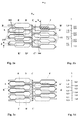
- Figures 1a and 1b and Figures 1c and 1d show two variants, according to which the FSIJIL print head according to the invention can be manufactured.
- the two variants differ only in the sequence of periodic arrangement of nozzles which chambers the first and second levels or left and right Half of the printhead are assigned. Nozzles each the nozzle group 1.1, 1.2, 1.3 and 1.4 belong to one Chamber of chamber groups 101, 102, 103, 104.
- FIG. 1a The face shooter ink jet in-line print head is shown in FIG. 1a in plan view from the nozzle side on the second chamber plate according to the invention from the nozzle side shown here in the first variant.
- the one below lying chambers of the known first chamber plate are drawn with dashed lines to their position relative to to clarify the second chamber plate according to the invention.
- the coverage area F of a chamber of the Chamber group 102 in the second chamber plate with one Chamber of chamber group 104 in the first chamber plate is hatched. Both chambers have one Offset of size X in the x direction and an offset of Size Z in the z direction.
- the individual chamber groups are mutually offset in the x and z directions.
- the a nozzle group 1.1, 1.2, 1.3, 1.4 forming nozzles are arranged in a row in a direction z.
- the Ink drops become in one of the x and z directions eject orthogonal y direction.
- the associated Chamber groups 101, 102 are in the x direction and Chamber groups 103, 104 are in one of these two Directions x and z offset orthogonal direction y arranged.
- the nozzle groups are with the corresponding ones in the chamber plates 3 or 2 located chamber groups 101, 102, 103, 104 via ink channels in communication to supply the ink. It is provided that in the Nozzle row the nozzles of the nozzle groups with nozzles of the other nozzle groups alternate.
- FIG. 1b shows the nozzle arrangement for explanation in the nozzle line after the first variant of the FSIJIL print head shown.
- FIG. 1c The face shooter ink jet in-line print head is shown in FIG. 1c in plan view of the second according to the invention Chamber plate from the nozzle side in the second Variant shown.
- the chambers below the known first chamber plate are also drawn in dashed lines to their position relative to to clarify the second chamber plate according to the invention.
- the coverage area F is in advantageously smaller than in Figure 1a.
- Figure 1d shows the nozzle arrangement in the nozzle line 1 after the second variant of the FSIJIL printhead.
- the nozzle row 1 includes the different Nozzle groups 1.1, 1.2, 1.3, 1.4 belonging to which nozzles so alternate that the coverage of chamber groups one level with those of the other level only at the Chamber edges is effective.
- the coverage area F of each chamber of the Chamber group 101 or 102 in the second chamber plate with chambers of chamber group 103 or 104 in the first Chamber plate is due to the offset in the x and z directions minimizable.
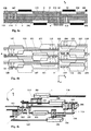
- FIG. 1c The sectional views in Figures 2a to 2e show the layered structure of the printhead and the Ink flow path according to the preferred embodiment the invention (second variant, Fig.1c).
- a first in a first level bearing ink chambers first chamber plate 2 is provided with means for feeding 151, 110 and actuators for driving out 10 of ink each chamber assigned to a nozzle.
- the print head from only 3 plates. There is one in each chamber plate 2, 3 Group 101, 102, 103, 104 of ink chambers on the Nozzle plate 4 facing side worked into it.
- the Inkjet printhead has a nozzle plate 4 after Face shooter principle.
- the nozzle plate 4 acts on the one hand as a membrane plate for the ink chambers of the second level. It also contains the nozzles and Nozzle channels 112 in the form of the cylindrical Nozzle plate with vertical through openings.
- the nozzle plate 4 is on the invention the second chamber plate supporting the ink chambers arranged and carries a single row of nozzles 1, those belonging to k chamber groups 101, 102, 103, 104, ... Has nozzle groups 1.1, 1.2, 1.3, 1.4, ... and which in the middle of the surface of the nozzle plate 4 is arranged.
- nozzles of a nozzle group 1.1, 1.2 via ink channels 115 with that in the same chamber plate 3 associated chamber group 101, 102 connected are and that at least one another Nozzle group 1.3, 1.4 via through openings 112 and Ink channels 111 in the aforementioned first chamber plate 2 with the associated chambers at least one further chamber group 103, 104 are connected.
- FIG. 2b shows a section B-B ' Ink channel guide from the suction chamber 151 of the Intake channel 110, 113, 114 to an ink chamber 102 the second level and from there via the nozzle channels 115, 112 to the associated nozzle.
- the chamber plate 3 in addition to the structure the ink chambers, the inflow (suction channels) the ink supply (suction chamber) and the nozzle channel too nor the vertical connection channels 112 from the ink chambers to the first chamber plate 2 has their associated nozzles in the nozzle plate 4.
- the chamber plate 2 contains the structures of the ink chambers and horizontal ink channels 111 and at least one suction chamber 151, 152 and horizontal connecting channels 110 (intake channels) to Intake space 151, 152.
- the section C-C 'shown in FIG. 2c is longitudinal the nozzle line 1 and in the y-direction of the nozzle axes placed. It illustrates how the interlocking of the Ink channels of the left and right half of the according 1c a particularly high plan view Density in the arrangement of the nozzles is reached.
- the Nozzle channels 112 of the left half are shown in bold.
- the associated ink chambers 101 and 103 are bold drawn in dashed lines.
- 2d is a section by the line D-D 'shown in FIG. 1c Top view shown for the left half, with the Cut through the chambers of the 1st level.
- Fig. 2e is a section through the line E-E 'on the the left half of the top view according to FIG. 1c has been placed, the section E-E 'through all chambers of the plane of left half goes.
- the passage openings can be in different ways are manufactured, so they can be etched with Laser beam burned out or with special tools to be punched. The choice of procedure depends on other from the material used.
- the nozzle plate 4 not only the nozzles but also the actuators 10 for changing the volume of the ink chambers is a homogeneous connection with the material the underlying chamber plate is required.
- the material the underlying chamber plate is required.
- the structuring including the formation of the nozzles is carried out by a photolithographic process and etching of the exposed parts reached.
- the homogeneous and dense final connection of the panels is done by thermal diffusion bonding.
- FIGS. 3a to 3c the invention (variant 3) shown, the Offset, as in principle in FIG. 1a to variant 1 already explained, was chosen.
- the print head consists of more than 3 plates, with a central plate 5 of thickness H as Spacer plate between the chamber plates 2 and 3 is used. This can while maintaining the Principle of the same nozzle channel length as that Offset in the x direction can be increased by the thickness H. This enables a further reduction in the Chamber overlap.
- the nozzle plate 4 acts as Cover plate for the second level ink chambers. In addition, it contains the nozzles in the form of cylindrical ones the plate vertically continuous openings.
- Figure 3a shows the section through - in the figure 1a shown - line A-A 'for part of the FSIJIL printhead according to the 3rd variant.
- Figure 3b shows the corresponding Section through the line B-B ',
- Figure 3c the section through the line C-C 'and the figure 3d den Section through line D-D 'for part of the FSIJIL printhead according to the third variant.
- Figure 3e shows the section through - in the figure 1a shown - line A-A 'for part of the FSIJIL printhead after a modified third Variant with another spacer plate 7.
- the corresponding cuts through the lines B-B 'and C-C' for part of the FSIJIL printhead do not have to are explained in detail because they are similar to the Cuts after the third variant are.
- FIGS 4c Another version with several rows of Ink channel groups 101 to 108 parallel and symmetrical the nozzle line per level is based on FIGS 4c explained for a fourth variant.
- the nozzle density can be doubled in this way.
- Figure 4a shows a section through the line A-A 'a part of FSIJIL printhead, that shown in Fig. 4b Top view of the nozzle side of the fourth variant. Of the Course of nearby ink channels outside the section plane A-A 'is shown in dashed lines.
- FIG. 4b shows the fourth variant of a face shooter ink jet in-line print head in top view of the second chamber plate 3 (nozzle side) is shown.
- the chambers and ink channels underneath in the volume are drawn with dashed lines.
- FIGS. 4a and 4b It can be seen from FIGS. 4a and 4b that the Ink channels between the chambers in the volume of the module lie. According to the distance between the aforementioned series of ink channel groups within each level increased so that this leads to another Minimizing the coverage area leads. So can with good results also the offset after the first principle variant Fig. 1a can be applied.
- FIG. 4c illustrates the ink guidance in FIG perspective view for a detail of the FSIJIL printhead to the right of the nozzle line 1 related to the Figures 4a and 4b.
- Each ink channel 111 or 115 has Ink guide sections in other layers and group 101 and 103 and 102 ink chambers and 104 are one path closer to the nozzle line arranged.
- the ink chambers are the additional groups 105 and 107 and 106 and 108 arranged closer to the suction space 151, 152 and each Ink input channel 124 and 120 thus have sections the ink guide in other levels.
- the conductor track guidance is shown in FIGS. 5 and 9 Contacting the PZT elements on the nozzle side evident.
- the conductor track on the circuit side is arranged comparable.
- this module is in another one pending application shown in more detail.
- driver switching circuit comes for example the type HV 04 or HV 06 in HVCMOS technology from Supertexinc. to the Commitment.
- the suction spaces 151, 152 combine at the Periphery of the module to a room 150, one of which Passage 153 to an attenuator 154 on the Surface (circuit side) of the module leads the via feed channels 155, 156 with an ink supply opening connected is.
- Module 200 has holes 177 for fastening of the module and ground conductors 180 with connected Electrode surface 181. On the latter the respective PZT crystal is later arranged and contacted. The other electrode on the surface of the PZT crystal is attached using a bonded wire the associated interconnect 190 connected to the corresponding output of the driver circuit leads.
- Figure 6 shows a cut in line A-A ' Section of the FSIJIL printhead according to the invention a first variant.
- Circuit 160 and the Actuators 10 are formed by outer plastic molded parts 170, 171 protected against environmental influences.
- the PZT elements are via bonded wires 131, 132 with conductor tracks 190, 191. which to the above drive circuit 160 lead.
- a flat cable 185 provides the Connection to the control electronics, for example one Franking machine, fro. Between the print head and the surface of the mail 100 a defined distance is maintained.
- the advantages of the defined offset are based on that on the one hand material properties between the individual wafers and on the other hand the individual process parameters be balanced with each other, that is, that all parts for the same print module are made from the same wafer and the same process.
- the manufacturing process for the invention FSIJIL printhead is based on the use of a wafer made of photosensitive glass, on which a mask is launched. After exposure to UV light turns on the exposed areas by heat treatment Phase transformation of amorphous materials into their crystalline Phase. Etching then becomes crystalline Material removed in layers, like that of IBM had been proposed in US 4,092,166.
- Step a) consists of several sub-steps a1) to a3), which are designed differently can be.
- the depth accuracy when etching the areas for continuous Holes is smaller than when etching very flat areas for the channels in the chamber parts and where first the through holes, then the chambers and then the nozzle channels are etched. It is further provided that the thickness of the bottom layer is monitored during the etching of the chambers and that the for Completion of the manufacture of the chambers required Thickness of the bottom layer (membrane) of the chambers Fine grinding each of the chamber parts is achieved.
- step a3) Before separating into individual chamber plates or Nozzle plates in step b) takes place in step a3) Application of the conductor tracks.
- the traces will but are preferably also produced by sputtering other processes, such as conventional photoresist and metallization processes suitable. Metals are made as possible used a subsequent annealing process survive. It is known from DE OS 37 33 109 platinum or to use platinum group metals that Endure sintering process up to 1300 ° C.
- Step b) The individual parts for the chamber parts, if necessary, the spacer or for the nozzle plate of each module are in Step b) separated and then into a module connected, whereby the individual parts are aligned. After the individual parts have been tacked together, a Module was created, which is then annealed. During the tempering there is a phase transition in the glass material from amorphous to crystalline instead.
- step c) the application of further electrical conductor tracks on the chamber surface, the application of the piezo crystals and that Contact in a manner known per se.
- the Piezo crystals can be glued on individually then curing the adhesive.
- it can also a layer of piezoelectric material on the chamber surface provided with conductor tracks which are later structured and applied is contacted. It is envisaged that the PZT layer first separated into individual PZT elements becomes. For this purpose, a Laser beam processing used. After applying further conductor tracks are contacted PZT elements.
- the last step d) is the assembly of the modules to a printhead.
- Figure 8 shows a fifth variant for the structure an ink jet print head in which the ink chambers the second chamber plate from the opposite Page were arranged in a structured manner. By doing Case no additional cover plate is required, which closes the ink chambers down. Instead of which is used to seal off the ink chambers a middle plate is used.
- an ink jet print head is made of several modules are built up in blocks.
- Such Block construction is known for example from US 4,703,333.
- the chamber parts for the lower levels simultaneously with those for the upper level and simultaneously with the spacers or the nozzle plate a common glass plate.
- the inkjet printhead that works on the face-shooter principle a row of nozzles in the surface of a nozzle plate arranged in the z-direction contains an ink jet allowed to eject in the y direction, existing thus from several modules.
- On a first level a chamber plate carrying the ink chambers with a Membrane arranged, each chamber part means for Feed and drive ink out of each chamber assigned. It is provided according to the invention that at least one additional chamber plate 3 in.
- a further level between the nozzle plate 4 and the first chamber plate 2 is arranged and chamber groups has, the chamber groups at least one Chamber plate 2, 3 per module symmetrical to nozzle row 1 of the respective module, which are in the middle of each Module on the printed side in the nozzle plate 4 is arranged and wherein the nozzle plate 4 membrane areas 20, which with ink expulsion means 10 are provided.
- the invention are in one level contiguous complexes of similar chamber plates or nozzle plates, if necessary, spacer plates arranged. It is provided that at least the structures the chamber plates 2, 3 and nozzle plate 4 each two modules in the respective x, z plane in the z direction offset by a maximum of half the nozzle distance are worked in side by side.
- the nozzle row 1 in the nozzle plate 4 of each module comprises several Nozzle groups 1.1, 1.2, 1.3 and 1.4, each module the inkjet printhead at least one group 101, 102 of ink chambers on that of the nozzle plate 4 facing side of the second chamber plate 3, where at least one nozzle group 1.1, 1.2 with the in the same chamber plate 3 associated chamber groups 101, 102 is connected, and at least one further nozzle group 1.3, 1.4 through through openings in the aforementioned chamber plate 3 with the associated Chambers at least one more on the first level chamber group 103, 104 located in chamber plate 2 connected is.
- the conductor track is on the nozzle side one due to the manufacturing process mentioned above manufactured FSIJIL printhead according to the sixth variant partially shown.
- the neighboring ones Modules of each complex are in the x-direction from each other spaced on the glass plate to accommodate the to create necessary electrical conductor tracks.
- Step aa first through holes and vertical Nozzle channels and non-continuous openings and chambers manufactured at the same time.
- first Areas e.g. continuous nozzle channels
- second areas e.g. Chambers
- the first conductor tracks be applied (by sputtering).
- the middle parts are also provided with conductor tracks can.
- the module plates are through Sputter coated with a metal. This can routing from the other layers to the upper layers of the module are cross-free, especially when very many items to contact are.
- step b) separation there is a sub-step b1) Separating the required parts of the module from the Glass plate or the related complexes. It is provided that spacers between the modules lie or are additionally arranged and that the Spacers made from the same sheet material structuring before separating is provided by etching in step aa3).
- the individual module parts are aligned in sub-step b2) stapled and annealed, one Phase transition from amorphous to crystalline takes place.
- FIG. 7c This further production method is shown in FIG. 7c shown.
- Step bb) includes based on the previous one So step ii) is not a sub-step to connect Individual parts or related complexes.
- the Separation is advantageously possible if the individual Module plates or related complexes only are connected to each other via webs, which are allow to be cut easily, preferably by sawing.
- the lands are previously etched in the first Process step aaa) produced. After execution steps aaa), i), ii) and bb) become the others Steps c) and d) performed.
- the invention is not based on the present Embodiment limited. Rather is a number of variants conceivable, which of the shown Solution even with fundamentally different types Make use of the remarks.
Description
- Figur 1a,
- erste Variante eines Face-Shooter-Ink-Jet-In-Line-Druckkopfes in Draufsicht auf die zweite Kammerplatte (Düsenseite)
- Figur 1b,
- Düsenanordnung in der Düselinie nach der ersten Variante des FSIJIL-Druckkopfes
- Figur 1c,
- zweite Variante eines Face-Shooter-Ink-Jet-In-Line-Druckkopfes in Draufsicht auf die zweite Kammerplatte (Düsenseite)
- Figur 1d,
- Düsenanordnung in der Düselinie nach der zweiten Variante des FSIJIL-Druckkopfes
- Figur 2a,
- Schnitt durch die Linie A-A'eines Teils des FSIJIL-Druckkopfes nach Variante zwei Fig. 1c
- Figur 2b,
- Schnitt durch die Linie B-B'eines Teils des FSIJIL-Druckkopfes nach Variante zwei
- Figur 2c,
- Schnitt durch die Linie C-C'eines Teils
- Figur 2d,
- Schnitt durch die Linie D-D'eines Teils
- Figur 2e,
- Schnitt durch die Linie E-E'eines Teils
- Figur 3a,
- Schnitt durch die Linie A-A'eines Teils des FSIJIL-Druckkopfes nach der dritten Variante
- Figur 3b,
- Schnitt durch die Linie B-B'eines Teils des FSIJIL-Druckkopfes nach der dritten Variante
- Figur 3c,
- Schnitt durch die Linie C-C'eines Teils des FSIJIL-Druckkopfes nach der dritten Variante
- Figur 3d,
- Schnitt durch die Linie D-D' eines Teils des FSIJIL-Druckkopfes nach der dritten Variante
- Figur 3e,
- Schnitt durch die Linie A-A' eines Teils des FSIJIL-Druckkopfes nach einer weiteren modifizierten dritten Variante
- Figur 4a,
- Schnitt durch die Linie A-A' eines Teils des FSIJIL-Druckkopfes nach der vierten Variante
- Figur 4b,
- Draufsicht auf die zweite Kammerplatte (Düsenseite) nach der vierte Variante,
- Figur 4c,
- perspektivische Ansicht der Tintenführung nach der vierte Variante,
- Figur 5,
- Leiterbahnführung auf der Düsenseite des FSIJIL-Druckkopfes nach der ersten Variante
- Figur 6,
- Schnitt durch die Linie A-A'eines Teils des FSIJIL-Druckkopfes nach der ersten Variante
- Figur 7a,
- Herstellungsverfahren Variante eins,
- Figur 7b,
- Herstellungsverfahren Variante zwei,
- Figur 7c,
- Herstellungsverfahren Variante drei,
- Figur 8,
- Fünfte Variante des Aufbaues eines Moduls des erfindungsgemäßen FSIJIL-Druckkopf,
- Figur 9,
- Leiterbahnführung auf der Düsenseite des FSIJIL-Druckkopfes nach einer sechsten Variante,
Die Figur 7b zeigt folgende Schritte:
Claims (16)
- Tintenstrahldruckkopfmodul für einen Tintenstrahldruckkopf nach dem Face-Shooter-Prinzip, wobei der Tintenstrahldruckkopfmodul aufgebaut ist aus Modulplatten vom Typeiner Düsenplatte (4) in einer x/z-Ebene, wobei in der Fläche der Düsenplatte (4) eine Düsenreihe (1) in z-Richtung angeordnet ist, die einen Tintenstrahl in y-Richtung auszustoßen gestattet,einer ersten Kammerplatte (2) in einer ersten x/z-Ebene mit einer auf der der Düsenplatte zugewandten Seite hineingearbeiteten Gruppe an Tintenkammern, wobei jeder Tintenkammer Kanäle zum Zu- und Abführen von Tinte, eine Membran Sowie ein Aktuator (10) zum Austreiben von Tinte zugeordnet sind,mindestens einer weiteren Kammerplatte (3) mit Tintenkammern, wobei die weitere Kammerplatte (3) in einer weiteren x/z-Ebene zwischen der Düsenplatte (4) und der ersten Kammerplatte (2) angeordnet ist, wobei jeder Tintenkammer Kanäle zum Zu- und Abführen von Tinte, Membran und Aktuator (10) zum Austreiben von Tinte aus jeder Tintenkammer zugeordnet sind,wobei die einzelnen Kammergruppen (101 und 103 bzw. 102 und 104) der Kammerplatten (2, 3) gegeneinander in x- und z-Richtung derart versetzt sind, so daß eine annähernd gleiche Kanallänge von jeder Tintenkammer zur zugehörigen Düse in der Düsenlinie erreicht wird und die Überdeckungsflächen (F) von Tintenkammern der Kammerngruppen der einen x/z-Ebene mit denen der anderen x/z-Ebene minimiert ist, um den cross talk-Effekt zwischen den vorgenannten ersten und Weiteren x/z-Ebenen gelegenen Tintenkammern zu verringern.
- Tintenstrahldruckkopfmodul nach Anspruch 1, dadurch gekennzeichnet, daß eine einzige Düsenreihe (1) in der Düsenplatte (4) vorgesehen ist, die mehrere Düsengruppen (1.1, 1.2, 1.3, 1.4) umfaßt, wobei die weitere Kammerplatte (3) mindestens eine Gruppe (101, 102) von Tintenkammern auf der der Düsenplatte (4) zugewandten Seite der zweiten Kammerplatte (3) aufweist, mindestens eine Düsengruppe (1.1, 1.2) mit der in derselben Kammerplatte (3) gelegenen zugehörigen Kammergruppen (101,102) über Kanäle verbunden ist, und mindestens eine weitere Düsengruppe (1.3, 1.4) über Durchgangsöffnungen in der vorgenannten zweiten Kammerplatte (3) mit den zugehörigen Kammern mindestens einer weiteren auf der ersten x/z-Ebene in der ersten Kammerplatte (2) gelegenen Kammergruppe (103, 104) verbunden ist, wobei in der Düsenreihe (1) die zu unterschiedlichen Düsengruppen (1.1, 1.2, 1.3, 1.4) gehörigen Düsen so alternieren, daß die Überdeckung von Kammerngruppen der einen Ebene mit denen der anderen Ebene nur an den Kammerrändern wirksam ist.
- Tintenstrahldruckkopfmodul nach den Ansprüchen 1 und 2, dadurch gekennzeichnet, daß die Tintenkammern zur Düsenreihe (1) einerseits und zu einem Ansaugraum (151, 152) andererseits derart angeordnet sind, daß in den Kammerplatten (2, 3) unterschiedlich lange Düsenkanäle (111, 112, 115, 121, 125) und Einlaßkanäle (110, 113, 114, 120, 124) vorgesehen sind, wobei die Summe der Tintenkanallängen je Kammer annähernd konstant bleibt.
- Tintenstrahldruckkopfmodul nach den Ansprüchen 1 bis 3, dadurch gekennzeichnet, daß die Tintenkammern wenigstens einer Kammerplatte (2, 3) in Kammergruppen symmetrisch zur Düsenreihe (1) liegen, die in der Mitte des Tintenstrahldruckkopfmoduls auf der Aufdruckseite in der Düsenplatte (4) angeordnet ist
- Tintenstrahldruckkopfmodul nach einem der vorgenannten Ansprüche 1 bis 4, dadurch gekennzeichnet, daß in jeder Kammerplatte (2, 3) mehrere Reihen von Kammergruppen (101, 102, 105, 106; 103, 104, 107, 108) parallel und symmetrisch zur Düsenreihe (1) angeordnet sind, wobei unter den Kammergruppen (103, 104, 107, 108) der ersten Ebene in mindestens einer zweiten Ebene symmetrisch zur Düsenreihe (1) Tintenkammern einer weiteren Kammergruppe (101, 102, 105, 106) angeordnet sind, welche seitlich in z-Richtung und zur Düsenreihe (1) in x-Richtung versetzt liegen.
- Tintenstrahldruckkopfmodul nach den Ansprüchen 1 bis 5, dadurch gekennzeichnet, daß zwischen der ersten (2) und zweiten Kammerplatte (3) mindestens eine Tintenkanäle aufweisende Abstandsplatte (5, 7) angeordnet ist.
- Tintenstrahldruckkopfmodul nach den Ansprüchen 1 bis 6, dadurch gekennzeichnet, daß durch die in einer zu diesen beiden Richtungen x und z orthogonalen y-Richtung angeordneten Kammergruppen (103, 104, 107, 108) und durch eine ins Volumen gelegte Tintenführung außerhalb der Ebene, in der sich die Tintenkammern der vorgenannten Kammergruppen befinden, wobei die Tintenführung teilweise zwischen den Kammern in weiteren Ebenen in Kanälen erfolgt, der Abstand zwischen den vorgenannten Reihen von Tintenkammergruppen (101 und 105 bzw. 102 und 106 sowie 103 und 107 bzw. 104 und 108) innerhalb jeder Kammerplatte (2, 3) soweit erhöht wird, so daß die Überdeckungsfläche F von jeder Tintenkammer der Kammergruppe (101, 105 bzw. 102, 106) der zweiten Kammerplatte (3) mit Kammern der Kammergruppe (103, 105 bzw. 104, 108) in der ersten Kammerplatte (2) durch den Versatz in x- und z-Richtung minimal wird.
- Tintenstrahldruckkopfmodul nach den Ansprüchen 1 bis 3, dadurch gekennzeichnet, daß der Tintenstrahldruckkopfmodul in wenigsten einer Kammerplatte (2, 3) Kammergruppen in mehreren Reihen parallel zur Düsenreihe (1) und in unterschiedlicher Entfernung zur Düsenreihe (1) angeordnet enthält.
- Tintenstrahldruckkopfmodul nach einem der vorgenannten Ansprüche 1 bis 8, dadurch gekennzeichnet, daß in jede Kammerplatte (2, 3) eine Gruppe an Tintenkammern auf der der Düsenplatte (4) zugewandten Seite hineingearbeitet ist, wobei die Düsenplatte (4) hineingearbeitete Membranbereiche (20) für die Tintenkammern der weiteren Kammerplatte (3) aufweist, die mit zugeordneten Aktuatoren (10) zum Austreiben von Tinte aus jeder Tintenkammer versehen sind, daß die Aktuatoren (10) auf Membranbereichen (20) der Düsenplatte (4) und die Aktuatoren (10) auf Membranbereichen der ersten Kammerplatte (2) PZT-Ebenen bilden, sowie daß auf der zur Düsenseite abgewandten Seite des Moduls mindestens ein Treiberschaltkreis (160) angeordnet ist, welcher über elektrische Leiterbahnen (180, 181, 190) ausgangsseitig mit den PZT-Ebenen und eingangsseitig mit einem Flachbandkabel (185) verbunden ist.
- Herstellungsverfahren für einen Tintenstrahldruckkopf mit Tintenstrahldruckkopfmodulen nach Anspruch 1, mit einer parallelen Bearbeitung einer Glasplatte zur Herausbildung von Bohrungen, vertikalen Düsenkanälen, Öffnungen und Kammern,
gekennzeichnet durch die Schritte:a) Herstellung von unterschiedlichen Modulplatten durch die parallele Bearbeitung einer Glasplatte zur Herausbildung mindestens der Bohrungen und vertikalen Düsenkanäle und der Öffnungen und Kammern und Schritte zur Aufbringung von Leiterbahnen auf die vorgenannte Glasplatte,b) Separieren der Einzelteile aus der Glasplatte und Verbinden der Einzelteile zu einem Modul,c) Aufbringen von PZT-Elementen, ggf. Vereinzeln undd) Assemblieren der Module zu einem Druckkopf - Herstellungsverfahren, nach Anspruch 10, dadurch gekennzeichnet, daß der Herstellungsschritt a) der eine parallele Bearbeitung einer Glasplatte zur Herausbildung mindestens der Bohrungen und vertikalen Düsenkanälen und der Öffnungen und Kammern aufweist, im Subschritt a1) Maßnahmen vorsieht, entsprechende vertikale Düsenkanäle in das die Düsenplatte des Moduls bildende Glasstück zu ätzen bzw. auf vergleichbare Weise einzubringen, daß der Subschritt a1) auch das Herausbilden von horizontalen Düsenkanälen, Trennlinien und Einlaßkanäle mit umfaßt und daß ein nachfolgender Subschritt a2) vorgesehen ist, in dem die Herstellung von Kanälen vorbestimmter Tiefe durch Feinschleifen der einen Seite und die Herstellung von Membranen vorbestimmter Dicke durch Feinschleifen der anderen Seite der Glasplatte erfolgt.
- Herstellungsverfahren, nach Anspruch 10, dadurch gekennzeichnet, daß der Herstellungsschritt a) der eine parallele Bearbeitung einer Glasplatte zur Herausbildung mindestens der Bohrungen und vertikalen Düsenkanälen und der Öffnungen und Kammern aufweist, zur Herstellung von unterschiedlichen Modulplatten innerhalb einer Glasplatte folgende Subschritte vorsieht:aa1) die parallele Bearbeitung einer Glasplatte zur Herausbildung mindestens der Bohrungen, vertikalen Düsenkanäle, der Öffnungen und Kammern,aa2) Feinschleifen der einen Seite und Herstellung von Membranen vorbestimmter Dicke durch Feinschleifen der anderen Seite der Glasplatte,aa3) Herstellen von horizontalen Düsenkanälen, Trennlinien und Einlaßkanälen durch Ätzen und Herstellung von Kanälen vorbestimmter Tiefe durch Feinschleifen der einen Seite der Platte,aa4) Aufbringung von Leiterbahnen auf die vorgenannte Glasplatte.
- Herstellungsverfahren für einen Tintenstrahldruckkopf mit Tintenstrahldruckkopfmodulen nach Anspruch 1, mit aaa) Herstellung eines Satzes von gleichen Modulplatten auf separaten Wafern, einschließlich einem Schritt a1) parallele Bearbeitung einer Glasplatte zur Herausbildung mindestens einer Kavität,
gekennzeichnet, durch weitere Schritte:i) Herstellung von weiteren Sätzen an gleichen Modulplatten auf separten Wafern gemäß dem vorgenannten Schritt aaa), wobei der Schritt aaa) Herstellung von gleichen Modulplatten auf separaten Wafern neben a1) paralleler Bearbeitung zur Herausbildung mindestens einer der Bohrungen, vertikalen und horizontalen Düsenkanäle, der Öffnungen, Kammern, Trennlinien, Einlaßkanäle, die folgenden Subschritte mit umfaßt:und weitere Schritte:a2) Herstellen von Kanälen vorbestimmter Tiefe durch Feinschleifen der einen Seite und Herstellen von Membranen vorbestimmter Dicke durch Feinschleifen der anderen Seite der Glasplatte,a3) Aufbringung von Leiterbahnen auf die vorgenannte Glasplatte,ii) Verbinden der Wafer zu einem Glasplattenverbund mit einer Vielzahl von Modulen,bb) Separieren der einzelnen oder zusammenhängenden Module aus dem Glasplattenverbund,c) Aufbringen von PZT-Elementen, ggf. Vereinzeln, sowied) Assemblieren der Module zu einem Druckkopf. - Herstellungsverfahren, nach einem der vorgenannten Ansprüche 10-13, dadurch gekennzeichnet, daß, nach dem Aufbringen von PZT-Elementen (c) und vor dem Assemblieren (d) der Module zu einem Druckkopf, ein weiteres Aufbringen der Leiterbahnen auf die Glasplatte erfolgt, wobei vorzugsweise zum Aufbringen der Leiterbahnen ein Sputtern vorgesehen ist.
- Herstellungsverfahren, nach einem der vorgenannten Ansprüche 10-14, dadurch gekennzeichnet, daß im Schritt c) das Kontaktieren der PZT-Elemente auf der entsprechenden Seite jeder einzelnen Modulplatte erfolgt.
- Herstellungsverfahren, nach einem der vorgenannten Ansprüche 10-15, dadurch gekennzeichnet, daß beim Ätzen von Öffnungen im ersten Herstellungsschritt zwischen den Modulplatten Stege gebildet werden, die sich im Verfahrensschritt Separieren leicht durchtrennen lassen.
Applications Claiming Priority (2)
| Application Number | Priority Date | Filing Date | Title |
|---|---|---|---|
| DE4336416A DE4336416A1 (de) | 1993-10-19 | 1993-10-19 | Face-Shooter-Tintenstrahldruckkopf und Verfahren zu seiner Herstellung |
| DE4336416 | 1993-10-19 |
Publications (3)
| Publication Number | Publication Date |
|---|---|
| EP0648607A2 EP0648607A2 (de) | 1995-04-19 |
| EP0648607A3 EP0648607A3 (de) | 1996-03-20 |
| EP0648607B1 true EP0648607B1 (de) | 1998-10-14 |
Family
ID=6500995
Family Applications (1)
| Application Number | Title | Priority Date | Filing Date |
|---|---|---|---|
| EP94250212A Expired - Lifetime EP0648607B1 (de) | 1993-10-19 | 1994-08-24 | Tintenstrahldruckkopfmodul für einen Face-Shooter-Tintenstrahldruckkopf und Verfahren zu seiner Herstellung |
Country Status (5)
| Country | Link |
|---|---|
| US (3) | US5752303A (de) |
| EP (1) | EP0648607B1 (de) |
| CA (1) | CA2125250C (de) |
| DE (2) | DE4336416A1 (de) |
| IL (1) | IL111422A0 (de) |
Families Citing this family (63)
| Publication number | Priority date | Publication date | Assignee | Title |
|---|---|---|---|---|
| JP3987139B2 (ja) * | 1995-06-27 | 2007-10-03 | セイコーエプソン株式会社 | インクジェット式記録ヘッド |
| US5907340A (en) * | 1995-07-24 | 1999-05-25 | Seiko Epson Corporation | Laminated ink jet recording head with plural actuator units connected at outermost ends |
| US6729002B1 (en) * | 1995-09-05 | 2004-05-04 | Seiko Epson Corporation | Method of producing an ink jet recording head |
| JPH09272205A (ja) * | 1996-04-04 | 1997-10-21 | Seiko Epson Corp | 積層型インクジェット式記録ヘッド |
| DE69719747T2 (de) * | 1996-11-18 | 2004-02-05 | Seiko Epson Corp. | Tintenstrahlschreibkopf |
| US7337532B2 (en) | 1997-07-15 | 2008-03-04 | Silverbrook Research Pty Ltd | Method of manufacturing micro-electromechanical device having motion-transmitting structure |
| US6857724B2 (en) * | 1997-07-15 | 2005-02-22 | Silverbrook Research Pty Ltd | Print assembly for a wide format pagewidth printer |
| US6935724B2 (en) | 1997-07-15 | 2005-08-30 | Silverbrook Research Pty Ltd | Ink jet nozzle having actuator with anchor positioned between nozzle chamber and actuator connection point |
| US7468139B2 (en) | 1997-07-15 | 2008-12-23 | Silverbrook Research Pty Ltd | Method of depositing heater material over a photoresist scaffold |
| US7465030B2 (en) | 1997-07-15 | 2008-12-16 | Silverbrook Research Pty Ltd | Nozzle arrangement with a magnetic field generator |
| US7195339B2 (en) | 1997-07-15 | 2007-03-27 | Silverbrook Research Pty Ltd | Ink jet nozzle assembly with a thermal bend actuator |
| US7303254B2 (en) * | 1997-07-15 | 2007-12-04 | Silverbrook Research Pty Ltd | Print assembly for a wide format pagewidth printer |
| US6712453B2 (en) | 1997-07-15 | 2004-03-30 | Silverbrook Research Pty Ltd. | Ink jet nozzle rim |
| US6855264B1 (en) | 1997-07-15 | 2005-02-15 | Kia Silverbrook | Method of manufacture of an ink jet printer having a thermal actuator comprising an external coil spring |
| US6648453B2 (en) | 1997-07-15 | 2003-11-18 | Silverbrook Research Pty Ltd | Ink jet printhead chip with predetermined micro-electromechanical systems height |
| US7556356B1 (en) | 1997-07-15 | 2009-07-07 | Silverbrook Research Pty Ltd | Inkjet printhead integrated circuit with ink spread prevention |
| US7891767B2 (en) * | 1997-07-15 | 2011-02-22 | Silverbrook Research Pty Ltd | Modular self-capping wide format print assembly |
| US6682174B2 (en) | 1998-03-25 | 2004-01-27 | Silverbrook Research Pty Ltd | Ink jet nozzle arrangement configuration |
| EP2000307B1 (de) * | 1997-07-18 | 2013-09-11 | Seiko Epson Corporation | Tintenstrahlaufzeichnungskopf, Herstellungsverfahren dafür und Tintenstrahlaufzeichnungsvorrichtung |
| US6036874A (en) * | 1997-10-30 | 2000-03-14 | Applied Materials, Inc. | Method for fabrication of nozzles for ink-jet printers |
| JP3267937B2 (ja) * | 1998-09-04 | 2002-03-25 | 松下電器産業株式会社 | インクジェットヘッド |
| US6726304B2 (en) * | 1998-10-09 | 2004-04-27 | Eastman Kodak Company | Cleaning and repairing fluid for printhead cleaning |
| US6656432B1 (en) * | 1999-10-22 | 2003-12-02 | Ngk Insulators, Ltd. | Micropipette and dividedly injectable apparatus |
| JP4269136B2 (ja) * | 1999-12-10 | 2009-05-27 | 富士フイルム株式会社 | インクジェットヘッドおよびインクジェットヘッドの製造方法並びに印刷装置 |
| JP4300565B2 (ja) * | 2000-03-27 | 2009-07-22 | 富士フイルム株式会社 | マルチノズルインクジェットヘッド及びその製造方法 |
| US6540339B2 (en) * | 2001-03-21 | 2003-04-01 | Hewlett-Packard Company | Flextensional transducer assembly including array of flextensional transducers |
| US20020196314A1 (en) * | 2001-06-25 | 2002-12-26 | Xerox Corporation | Piezoelectric transducer |
| KR100395529B1 (ko) * | 2001-10-30 | 2003-08-25 | 삼성전자주식회사 | 잉크젯 프린트 헤드 및 그 제조방법 |
| US6953241B2 (en) | 2001-11-30 | 2005-10-11 | Brother Kogyo Kabushiki Kaisha | Ink-jet head having passage unit and actuator units attached to the passage unit, and ink-jet printer having the ink-jet head |
| US6984027B2 (en) * | 2001-11-30 | 2006-01-10 | Brother Kogyo Kabushiki Kaisha | Ink-jet head and ink-jet printer having ink-jet head |
| CN1273298C (zh) * | 2002-02-18 | 2006-09-06 | 兄弟工业株式会社 | 喷墨打印头及具有喷墨打印头的喷墨打印机 |
| US6846069B2 (en) * | 2002-05-10 | 2005-01-25 | Brother Kogyo Kabushiki Kaisha | Ink-jet head |
| US7052117B2 (en) | 2002-07-03 | 2006-05-30 | Dimatix, Inc. | Printhead having a thin pre-fired piezoelectric layer |
| JP4218444B2 (ja) * | 2003-06-30 | 2009-02-04 | ブラザー工業株式会社 | インクジェットヘッドの製造方法 |
| US6890067B2 (en) * | 2003-07-03 | 2005-05-10 | Hewlett-Packard Development Company, L.P. | Fluid ejection assembly |
| US20050206679A1 (en) * | 2003-07-03 | 2005-09-22 | Rio Rivas | Fluid ejection assembly |
| JP2005035013A (ja) * | 2003-07-15 | 2005-02-10 | Brother Ind Ltd | 液体移送装置の製造方法 |
| US8491076B2 (en) | 2004-03-15 | 2013-07-23 | Fujifilm Dimatix, Inc. | Fluid droplet ejection devices and methods |
| US7281778B2 (en) | 2004-03-15 | 2007-10-16 | Fujifilm Dimatix, Inc. | High frequency droplet ejection device and method |
| JP4218594B2 (ja) * | 2004-06-08 | 2009-02-04 | ブラザー工業株式会社 | インクジェットヘッド |
| JP2006027132A (ja) * | 2004-07-16 | 2006-02-02 | Fuji Photo Film Co Ltd | 液滴吐出ヘッド及び画像形成装置 |
| KR20070087223A (ko) | 2004-12-30 | 2007-08-27 | 후지필름 디마틱스, 인크. | 잉크 분사 프린팅 |
| JP4770413B2 (ja) * | 2005-03-04 | 2011-09-14 | リコープリンティングシステムズ株式会社 | インクジェット式記録ヘッド |
| US7540593B2 (en) * | 2005-04-26 | 2009-06-02 | Hewlett-Packard Development Company, L.P. | Fluid ejection assembly |
| US7380914B2 (en) * | 2005-04-26 | 2008-06-03 | Hewlett-Packard Development Company, L.P. | Fluid ejection assembly |
| US7694398B2 (en) * | 2005-09-15 | 2010-04-13 | Fujifilm Corporation | Method of manufacturing a liquid ejection head |
| US7686432B2 (en) * | 2006-01-20 | 2010-03-30 | Samsung Electro-Mechanics Co., Ltd. | Inkjet printer head and fabricating method thereof |
| US7988247B2 (en) | 2007-01-11 | 2011-08-02 | Fujifilm Dimatix, Inc. | Ejection of drops having variable drop size from an ink jet printer |
| CN101977773B (zh) * | 2008-03-17 | 2013-08-07 | 惠普开发有限公司 | 一种打印头和用于制造打印头的方法 |
| US8814328B2 (en) * | 2011-12-13 | 2014-08-26 | Xerox Corporation | Polymer film as an interstitial fill for PZT printhead fabrication |
| JP6260096B2 (ja) * | 2013-03-27 | 2018-01-17 | セイコーエプソン株式会社 | 液体噴射ヘッドおよび液体噴射装置 |
| JP6318475B2 (ja) * | 2013-06-10 | 2018-05-09 | セイコーエプソン株式会社 | 流路ユニットおよび流路ユニットを搭載した液体噴射ヘッド、液体噴射装置 |
| JP6402573B2 (ja) * | 2014-10-08 | 2018-10-10 | ローム株式会社 | インクジェット装置およびインクジェット装置の製造方法 |
| JP6492756B2 (ja) * | 2015-02-25 | 2019-04-03 | ブラザー工業株式会社 | 液体吐出装置 |
| JP6520237B2 (ja) * | 2015-03-10 | 2019-05-29 | 株式会社リコー | 液滴吐出ヘッド、液体カートリッジおよび画像形成装置 |
| JP6447819B2 (ja) * | 2015-03-10 | 2019-01-09 | セイコーエプソン株式会社 | ヘッド及び液体噴射装置 |
| GB2547951A (en) * | 2016-03-04 | 2017-09-06 | Xaar Technology Ltd | Droplet deposition head and manifold component therefor |
| JP2017185826A (ja) * | 2017-07-14 | 2017-10-12 | セイコーエプソン株式会社 | 液体噴射ヘッド、及び、液体噴射装置 |
| JP7027950B2 (ja) * | 2018-02-24 | 2022-03-02 | 株式会社リコー | 液体吐出ヘッド、液体吐出ユニット、液体を吐出する装置 |
| WO2020189695A1 (ja) * | 2019-03-20 | 2020-09-24 | 京セラ株式会社 | 液体吐出ヘッドおよび記録装置 |
| JP2021088080A (ja) * | 2019-12-03 | 2021-06-10 | セイコーエプソン株式会社 | 液体噴射ヘッドおよび液体噴射システム |
| JP2021088083A (ja) | 2019-12-03 | 2021-06-10 | セイコーエプソン株式会社 | 液体噴射ヘッドおよび液体噴射システム |
| JP2023114029A (ja) * | 2022-02-04 | 2023-08-17 | セイコーエプソン株式会社 | 液体噴射ヘッド、及び、液体噴射装置 |
Citations (1)
| Publication number | Priority date | Publication date | Assignee | Title |
|---|---|---|---|---|
| US4769654A (en) * | 1982-09-01 | 1988-09-06 | Konishiroku Photo Industry Co., Ltd. | Ink jet printing head having plurality of ink-jetting units disposed parallel to circular-shaped reference plane |
Family Cites Families (46)
| Publication number | Priority date | Publication date | Assignee | Title |
|---|---|---|---|---|
| DE2349555C2 (de) * | 1973-04-25 | 1983-04-07 | Siemens AG, 1000 Berlin und 8000 München | Druckkopf für Farbflüssigkeits-Spritzdrucker und dergleichen |
| SE364385B (de) * | 1973-04-25 | 1974-02-18 | Original Odhner Ab | |
| US4216477A (en) * | 1978-05-10 | 1980-08-05 | Hitachi, Ltd. | Nozzle head of an ink-jet printing apparatus with built-in fluid diodes |
| AT368283B (de) * | 1980-11-07 | 1982-09-27 | Philips Nv | Duesenplatte fuer einen tintenstrahlschreibkopf und verfahren zur herstellung einer solchen duesen- platte |
| AT372651B (de) * | 1980-12-15 | 1983-11-10 | Philips Nv | Tintenstrahlschreibkopf und verfahren zur herstellung eines solchen tintenstrahlschreibkopfes |
| DE3117028A1 (de) * | 1981-04-29 | 1982-11-18 | Siemens AG, 1000 Berlin und 8000 München | Schreibkopf fuer tintenschreibeinrichtungen mit zylinderfoermigen tintenkanaelen |
| DE3222636A1 (de) * | 1981-06-18 | 1983-01-05 | Konishiroku Photo Industry Co., Ltd., Tokyo | Schreibkopf fuer einen tintenstrahlschreiber |
| US4611219A (en) * | 1981-12-29 | 1986-09-09 | Canon Kabushiki Kaisha | Liquid-jetting head |
| DE3311956A1 (de) * | 1982-03-31 | 1983-10-13 | Ricoh Co., Ltd., Tokyo | Farbstrahl-druckerkopf |
| JPS58187365A (ja) * | 1982-04-27 | 1983-11-01 | Seiko Epson Corp | オンデマンド型インクジエツト記録ヘツド |
| DE3445761A1 (de) * | 1983-12-16 | 1985-06-27 | Pitney Bowes, Inc., Stamford, Conn. | Verfahren und herstellung einer wandleranordnung |
| US4635079A (en) * | 1985-02-11 | 1987-01-06 | Pitney Bowes Inc. | Single element transducer for an ink jet device |
| US4601777A (en) * | 1985-04-03 | 1986-07-22 | Xerox Corporation | Thermal ink jet printhead and process therefor |
| US4641153A (en) * | 1985-09-03 | 1987-02-03 | Pitney Bowes Inc. | Notched piezo-electric transducer for an ink jet device |
| US4752788A (en) * | 1985-09-06 | 1988-06-21 | Fuji Electric Co., Ltd. | Ink jet recording head |
| US4730197A (en) * | 1985-11-06 | 1988-03-08 | Pitney Bowes Inc. | Impulse ink jet system |
| US4680595A (en) * | 1985-11-06 | 1987-07-14 | Pitney Bowes Inc. | Impulse ink jet print head and method of making same |
| US4703333A (en) * | 1986-01-30 | 1987-10-27 | Pitney Bowes Inc. | Impulse ink jet print head with inclined and stacked arrays |
| US4695854A (en) * | 1986-07-30 | 1987-09-22 | Pitney Bowes Inc. | External manifold for ink jet array |
| DE3764474D1 (de) * | 1986-10-16 | 1990-09-27 | Siemens Ag | Mehrschichtig aufgebauter tintenschreibkopf. |
| DE3710654A1 (de) * | 1987-03-31 | 1988-10-13 | Siemens Ag | Mehrschichtig aufgebauter tintenschreibkopf |
| US4835554A (en) * | 1987-09-09 | 1989-05-30 | Spectra, Inc. | Ink jet array |
| DE3730844A1 (de) * | 1987-09-14 | 1989-03-23 | Siemens Ag | Matrix-schreibeinrichtung |
| US4812859A (en) * | 1987-09-17 | 1989-03-14 | Hewlett-Packard Company | Multi-chamber ink jet recording head for color use |
| DE3803432A1 (de) * | 1988-02-05 | 1989-08-17 | Olympia Aeg | Piezoelektrisch betriebener schreibkopf in tintenmosaikschreibeinrichtungen |
| DE3805279A1 (de) * | 1988-02-19 | 1989-08-31 | Siemens Ag | Piezoelektrischer tintendruckkopf und verfahren zu seiner herstellung |
| GB8810241D0 (en) * | 1988-04-29 | 1988-06-02 | Am Int | Drop-on-demand printhead |
| DE3814720A1 (de) * | 1988-04-30 | 1989-11-09 | Olympia Aeg | Verfahren zur herstellung einer grundplatte mit durch aetzen hergestellte einarbeitungen fuer einen tintendruckkopf |
| US4878992A (en) * | 1988-11-25 | 1989-11-07 | Xerox Corporation | Method of fabricating thermal ink jet printheads |
| DE3917434A1 (de) * | 1989-05-29 | 1989-11-09 | Siemens Ag | Mehrschichtig aufgebauter tintendruckkopf mit durch selektives aetzen erzeugten tintenkanaelen |
| US5157420A (en) * | 1989-08-17 | 1992-10-20 | Takahiro Naka | Ink jet recording head having reduced manufacturing steps |
| JPH0392355A (ja) * | 1989-09-05 | 1991-04-17 | Seiko Epson Corp | インクジェットヘッド製造方法 |
| US5087930A (en) * | 1989-11-01 | 1992-02-11 | Tektronix, Inc. | Drop-on-demand ink jet print head |
| US5059989A (en) * | 1990-05-16 | 1991-10-22 | Lexmark International, Inc. | Thermal edge jet drop-on-demand ink jet print head |
| US5265315A (en) * | 1990-11-20 | 1993-11-30 | Spectra, Inc. | Method of making a thin-film transducer ink jet head |
| EP0488675A1 (de) * | 1990-11-28 | 1992-06-03 | Canon Kabushiki Kaisha | Herstellungsverfahren eines Farbstrahlaufzeichnungskopfes und Farbstrahlaufzeichnungskopf |
| JP2744536B2 (ja) * | 1991-10-04 | 1998-04-28 | 株式会社テック | インクジェットプリンタヘッド及びその製造方法 |
| US5194877A (en) * | 1991-05-24 | 1993-03-16 | Hewlett-Packard Company | Process for manufacturing thermal ink jet printheads having metal substrates and printheads manufactured thereby |
| JPH05104714A (ja) * | 1991-10-17 | 1993-04-27 | Canon Inc | 液体噴射記録ヘツドおよびその製造方法 |
| US5218754A (en) * | 1991-11-08 | 1993-06-15 | Xerox Corporation | Method of manufacturing page wide thermal ink-jet heads |
| JP2798845B2 (ja) * | 1992-03-26 | 1998-09-17 | 株式会社テック | インクジェットプリンタヘッドの製造方法 |
| JP2843199B2 (ja) * | 1992-03-26 | 1999-01-06 | 株式会社テック | インクジェットプリンタヘッドの製造方法 |
| JP3308337B2 (ja) * | 1992-04-02 | 2002-07-29 | ヒューレット・パッカード・カンパニー | インクジェット・プリンタ用プリントヘッド,インクジェット・プリンタ用プリントヘッドの形成方法及び部品組立方法 |
| DE4225799A1 (de) * | 1992-07-31 | 1994-02-03 | Francotyp Postalia Gmbh | Tintenstrahldruckkopf und Verfahren zu seiner Herstellung |
| US5365645A (en) * | 1993-03-19 | 1994-11-22 | Compaq Computer Corporation | Methods of fabricating a page wide piezoelectric ink jet printhead assembly |
| US5408739A (en) * | 1993-05-04 | 1995-04-25 | Xerox Corporation | Two-step dieing process to form an ink jet face |
-
1993
- 1993-10-19 DE DE4336416A patent/DE4336416A1/de not_active Withdrawn
-
1994
- 1994-06-06 CA CA002125250A patent/CA2125250C/en not_active Expired - Fee Related
- 1994-08-24 EP EP94250212A patent/EP0648607B1/de not_active Expired - Lifetime
- 1994-08-24 DE DE59407085T patent/DE59407085D1/de not_active Expired - Fee Related
- 1994-10-27 IL IL11142294A patent/IL111422A0/xx unknown
-
1995
- 1995-12-11 US US08/570,677 patent/US5752303A/en not_active Expired - Fee Related
-
1997
- 1997-02-04 US US08/795,324 patent/US6070972A/en not_active Expired - Fee Related
- 1997-03-18 US US08/820,669 patent/US5845380A/en not_active Expired - Fee Related
Patent Citations (1)
| Publication number | Priority date | Publication date | Assignee | Title |
|---|---|---|---|---|
| US4769654A (en) * | 1982-09-01 | 1988-09-06 | Konishiroku Photo Industry Co., Ltd. | Ink jet printing head having plurality of ink-jetting units disposed parallel to circular-shaped reference plane |
Also Published As
| Publication number | Publication date |
|---|---|
| CA2125250C (en) | 1999-10-05 |
| US5752303A (en) | 1998-05-19 |
| US5845380A (en) | 1998-12-08 |
| US6070972A (en) | 2000-06-06 |
| IL111422A0 (en) | 1994-10-27 |
| DE4336416A1 (de) | 1995-08-24 |
| EP0648607A3 (de) | 1996-03-20 |
| EP0648607A2 (de) | 1995-04-19 |
| DE59407085D1 (de) | 1998-11-19 |
| CA2125250A1 (en) | 1995-04-20 |
Similar Documents
| Publication | Publication Date | Title |
|---|---|---|
| EP0648607B1 (de) | Tintenstrahldruckkopfmodul für einen Face-Shooter-Tintenstrahldruckkopf und Verfahren zu seiner Herstellung | |
| EP0581395B1 (de) | Tintenstrahldruckkopf | |
| DE69908807T2 (de) | Tröpfchenaufzeichnungsgerät | |
| EP0713777B1 (de) | Anordnung für einen Tintendruckkopf aus einzelnen Tintendruckmodulen | |
| DE3630206C2 (de) | ||
| EP0615844B1 (de) | Modularer Tintenstrahldruckkopf | |
| DE69935179T2 (de) | Strukturierungstechnik unter Verwendung eines Templates und Tintenstrahlsystems | |
| DE69818666T2 (de) | Auf abruf arbeitende tintenstrahldruckvorrichtung | |
| DE69636021T2 (de) | Tintenstrahldruckkopf und Verfahren zu seiner Herstellung | |
| EP0695641B1 (de) | Anordnung für plattenförmige Piezoaktoren und Verfahren zu deren Herstellung | |
| DE60313233T2 (de) | Tintenstrahlkopf, Verfahren für dessen Herstellung, und Tintenstrahldrucker | |
| EP0691205B1 (de) | Tintendruckkopf aus einzelnen Tintendruckmodulen | |
| DE69928549T2 (de) | Auf Abruf arbeitende Tintenstrahldruckvorrichtung, Druckverfahren und Herstellungsverfahren | |
| DE69833154T2 (de) | Mikrovorrichtung | |
| DE3248087A1 (de) | Fluessigkeitsstrahlkopf | |
| DE2703320A1 (de) | Troepfchenstrahlen-aufzeichnungsvorrichtung | |
| DE4435914C2 (de) | Piezoelektrischer Antrieb für einen Tintenstrahlaufzeichnungskopf und Verfahren zu dessen Herstellung | |
| DE60222367T2 (de) | Flüssigkeitsausstosskopf | |
| EP0671270B1 (de) | Tintenstrahldruckkopf | |
| EP0713775B1 (de) | Anordnung für einen Tintendruckkopf aus einzelnen Tintendruckmodulen | |
| DE3804165A1 (de) | Verfahren zum bestuecken eines tintenstrahldruckkopfes mit piezokristallen | |
| DE69822928T2 (de) | Tintenstrahldruckkopf | |
| DE69935462T2 (de) | Verfahren zur Herstellung eines Tintenstrahl-Aufzeichnungskopfs | |
| DE10026133A1 (de) | Verfahren zum Herstellen eines Tintenstrahldruckkopfs | |
| DE69918191T2 (de) | Tintenstrahldruckkopf und herstellungsverfahren |
Legal Events
| Date | Code | Title | Description |
|---|---|---|---|
| PUAI | Public reference made under article 153(3) epc to a published international application that has entered the european phase |
Free format text: ORIGINAL CODE: 0009012 |
|
| AK | Designated contracting states |
Kind code of ref document: A2 Designated state(s): CH DE FR GB IT LI |
|
| PUAL | Search report despatched |
Free format text: ORIGINAL CODE: 0009013 |
|
| AK | Designated contracting states |
Kind code of ref document: A3 Designated state(s): CH DE FR GB IT LI |
|
| 17P | Request for examination filed |
Effective date: 19960419 |
|
| RAP1 | Party data changed (applicant data changed or rights of an application transferred) |
Owner name: FRANCOTYP-POSTALIA AKTIENGESELLSCHAFT & CO. |
|
| RAP3 | Party data changed (applicant data changed or rights of an application transferred) |
Owner name: FRANCOTYP-POSTALIA AKTIENGESELLSCHAFT & CO. |
|
| 17Q | First examination report despatched |
Effective date: 19970403 |
|
| GRAG | Despatch of communication of intention to grant |
Free format text: ORIGINAL CODE: EPIDOS AGRA |
|
| GRAG | Despatch of communication of intention to grant |
Free format text: ORIGINAL CODE: EPIDOS AGRA |
|
| GRAH | Despatch of communication of intention to grant a patent |
Free format text: ORIGINAL CODE: EPIDOS IGRA |
|
| GRAH | Despatch of communication of intention to grant a patent |
Free format text: ORIGINAL CODE: EPIDOS IGRA |
|
| GRAA | (expected) grant |
Free format text: ORIGINAL CODE: 0009210 |
|
| AK | Designated contracting states |
Kind code of ref document: B1 Designated state(s): CH DE FR GB IT LI |
|
| REG | Reference to a national code |
Ref country code: CH Ref legal event code: NV Representative=s name: ROTTMANN, ZIMMERMANN + PARTNER AG Ref country code: CH Ref legal event code: EP |
|
| REF | Corresponds to: |
Ref document number: 59407085 Country of ref document: DE Date of ref document: 19981119 |
|
| ET | Fr: translation filed | ||
| GBT | Gb: translation of ep patent filed (gb section 77(6)(a)/1977) |
Effective date: 19990115 |
|
| PLBE | No opposition filed within time limit |
Free format text: ORIGINAL CODE: 0009261 |
|
| STAA | Information on the status of an ep patent application or granted ep patent |
Free format text: STATUS: NO OPPOSITION FILED WITHIN TIME LIMIT |
|
| 26N | No opposition filed | ||
| REG | Reference to a national code |
Ref country code: GB Ref legal event code: IF02 |
|
| REG | Reference to a national code |
Ref country code: CH Ref legal event code: PUE Owner name: DIGITAL GRAPHICS INCORPORATION Free format text: FRANCOTYP-POSTALIA AKTIENGESELLSCHAFT & CO.#TRIFTWEG 21-26#16547 BIRKENWERDER (DE) -TRANSFER TO- DIGITAL GRAPHICS INCORPORATION#517, DEOKE-DON YANGJU-SHI#KYUNGGI-DO, 482-050 (KR) |
|
| REG | Reference to a national code |
Ref country code: FR Ref legal event code: TP |
|
| REG | Reference to a national code |
Ref country code: GB Ref legal event code: 732E |
|
| PGFP | Annual fee paid to national office [announced via postgrant information from national office to epo] |
Ref country code: FR Payment date: 20050804 Year of fee payment: 12 |
|
| PGFP | Annual fee paid to national office [announced via postgrant information from national office to epo] |
Ref country code: CH Payment date: 20050830 Year of fee payment: 12 |
|
| PG25 | Lapsed in a contracting state [announced via postgrant information from national office to epo] |
Ref country code: LI Free format text: LAPSE BECAUSE OF NON-PAYMENT OF DUE FEES Effective date: 20060831 Ref country code: CH Free format text: LAPSE BECAUSE OF NON-PAYMENT OF DUE FEES Effective date: 20060831 |
|
| PGFP | Annual fee paid to national office [announced via postgrant information from national office to epo] |
Ref country code: IT Payment date: 20060831 Year of fee payment: 13 |
|
| REG | Reference to a national code |
Ref country code: CH Ref legal event code: PL |
|
| REG | Reference to a national code |
Ref country code: FR Ref legal event code: ST Effective date: 20070430 |
|
| PGFP | Annual fee paid to national office [announced via postgrant information from national office to epo] |
Ref country code: DE Payment date: 20071031 Year of fee payment: 14 |
|
| PG25 | Lapsed in a contracting state [announced via postgrant information from national office to epo] |
Ref country code: FR Free format text: LAPSE BECAUSE OF NON-PAYMENT OF DUE FEES Effective date: 20060831 |
|
| PGFP | Annual fee paid to national office [announced via postgrant information from national office to epo] |
Ref country code: GB Payment date: 20071116 Year of fee payment: 14 |
|
| GBPC | Gb: european patent ceased through non-payment of renewal fee |
Effective date: 20080824 |
|
| PG25 | Lapsed in a contracting state [announced via postgrant information from national office to epo] |
Ref country code: DE Free format text: LAPSE BECAUSE OF NON-PAYMENT OF DUE FEES Effective date: 20090303 |
|
| PG25 | Lapsed in a contracting state [announced via postgrant information from national office to epo] |
Ref country code: IT Free format text: LAPSE BECAUSE OF NON-PAYMENT OF DUE FEES Effective date: 20070824 |
|
| PG25 | Lapsed in a contracting state [announced via postgrant information from national office to epo] |
Ref country code: GB Free format text: LAPSE BECAUSE OF NON-PAYMENT OF DUE FEES Effective date: 20080824 |