EP0648649A2 - Air bag module with a centrally mounted inflator using a clamshell inflator retention system - Google Patents
Air bag module with a centrally mounted inflator using a clamshell inflator retention system Download PDFInfo
- Publication number
- EP0648649A2 EP0648649A2 EP94307446A EP94307446A EP0648649A2 EP 0648649 A2 EP0648649 A2 EP 0648649A2 EP 94307446 A EP94307446 A EP 94307446A EP 94307446 A EP94307446 A EP 94307446A EP 0648649 A2 EP0648649 A2 EP 0648649A2
- Authority
- EP
- European Patent Office
- Prior art keywords
- module housing
- air bag
- module
- base
- inflator
- Prior art date
- Legal status (The legal status is an assumption and is not a legal conclusion. Google has not performed a legal analysis and makes no representation as to the accuracy of the status listed.)
- Ceased
Links
Images


Classifications
-
- B—PERFORMING OPERATIONS; TRANSPORTING
- B60—VEHICLES IN GENERAL
- B60R—VEHICLES, VEHICLE FITTINGS, OR VEHICLE PARTS, NOT OTHERWISE PROVIDED FOR
- B60R21/00—Arrangements or fittings on vehicles for protecting or preventing injuries to occupants or pedestrians in case of accidents or other traffic risks
- B60R21/02—Occupant safety arrangements or fittings, e.g. crash pads
- B60R21/16—Inflatable occupant restraints or confinements designed to inflate upon impact or impending impact, e.g. air bags
- B60R21/20—Arrangements for storing inflatable members in their non-use or deflated condition; Arrangement or mounting of air bag modules or components
- B60R21/217—Inflation fluid source retainers, e.g. reaction canisters; Connection of bags, covers, diffusers or inflation fluid sources therewith or together
Definitions
- This invention relates to an air bag module for use on the driver side of automotive and other vehicles wherein an inflatable air bag or cushion is inflated in the event of a collision to protect the driver from injury that could result from being forcibly thrown against the steering wheel, dashboard, etc.
- the air bag module uses a toroidal hybrid inflator assembly.
- Pyrotechnic inflator assemblies that currently are in use in driver side air bag modules, as disclosed, for example, in U.S. application for patent bearing Serial No. 07/820,826, filed January 15, 1992 by Gary V. Adams and Bradley W. Smith, typically are toroidal types having relatively flat disk-like shapes that include a flange.
- the modules currently produced use the flange of the toroidal inflator to attach it to the module housing.
- Inflator assemblies of the toroidal type as disclosed in the aforementioned U.S. application for patent bearing Serial No. 07/820,826, produce a cushion inflating gas source from a combustible gas generating material which, upon ignition, generates a quantity of gas sufficient to inflate the cushion.
- the cushion inflating gas results from a combination of stored compressed gas and a gas generating material, as disclosed, for example, in German patent Off. 2443 267 and in U.S. Patents 3,901,530 and 5,199,740.
- the latter form of toroidal inflator assembly is commonly referred to as a toroidal augmented gas or hybrid inflator.
- a toroidal hybrid inflator affects the performance of an air bag module in several ways including variation in the amount of stored gas, the transmission of heat to the stored gas, and the rate at which the inflating gas is dispensed into the inflatable cushion.
- the toroidal hybrid inflator is characterized in that it does not have a flange to attach it to the air bag module. There is thus a need and a demand to devise another method to attach the toroidal hybrid inflator to an air bag module thereby to eliminate the need for a flange to be welded thereto.
- the present invention was devised to fill the technological gap that has existed in the art in these respects.
- An object of the invention is to provide an air bag module for the driver side of an automotive or other vehicle which module uses a toroidal inflator assembly that is so clamped in the module that a flange is not needed, there being no change in the external appearance and function of the module and with only the internal components of the module being changed.
- Another object of the invention is to provide such an air bag module in which the toroidal inflator assembly is mounted in the center of the module.
- Still another object of the invention is to provide such an air bag module in which the toroidal inflator assembly is of the augmented gas or hybrid type.
- a further object of the invention is to provide such an air bag module in which the toroidal hybrid inflator assembly is held very firmly in position within the air bag module during the life of the module.
- Another object of the invention is to provide such an air bag module in which the inflating gas discharge exit openings of the toroidal hybrid inflator assembly are substantially sealed within the inflating gas inlet opening of the inflatable cushion stored in folded condition within the air bag module.
- An additional object of the invention is to provide such an air bag module in which the toroidal hybrid inflator assembly is of the "thrust neutral" type in which the gas discharge openings are so positioned that upon initiation of the inflator assembly the gas is discharged in opposing directions whereby there are not resulting forces tending to cause movement of the inflator assembly.
- the tubular inflator assembly is a hybrid type, a pressure vessel including a storage chamber that is filled and pressurized with an inert gas such as Argon or Nitrogen to a pressure typically in the range of 2000-4000 psi.
- the storage chamber is defined a toroidal container.
- a pyrotechnic heater typically is centrally positioned in sealing relation in the storage chamber from the bottom of the container.
- a diffuser protrudes, that is, projects outwardly from the upper surface of the container at a central location thereof.
- Provided in the diffuser are a plurality of gas exit ports or orifices for dispensing inflating gas uniformly in opposing directions in a thrust neutral manner from the pressurized chamber.
- the toroidal hybrid inflator assembly is partially positioned in a concave raised portion of the module housing.
- This raised portion is located substantially in the center of the housing and, closely matching the upper body portion contour of the toroidal hybrid inflator, allows the inflator to nest in the housing.
- the diffuser of the inflator protrudes through a hole in the center of the raised portion of the module housing into the area or space where the air bag or cushion would be packed.
- the contour of the raised portion of the module housing closely matches the inflator and normally would be half as deep as the inflator is thick. If the inflator needs to be moved into the module more to reduce the envelope size, the raised portion of the housing is made larger to accommodate the inflator.
- the cushion retaining ring in the air bag module for clamping the inflatable cushion to the module housing and the toroidal inflator assembly is the same type of rivetless retaining ring that is used in air bag modules of current design.
- the retaining ring encircles the raised concave portion of the housing.
- the cushion used in the module according to the preferred embodiment of the invention is the same as that which is currently used in driver side air bag modules.
- Fasteners such as studs or bolts, which have been pressed into the retaining ring, also extend through the fabric of the cushion, the module housing, and a retaining bracket. The module is held together with nuts on the studs or bolts.
- the retaining bracket has a concave lowered portion in it to support the lower or bottom half of the toroidal hybrid inflator assembly and to hold it in place.
- the lowered concave portion closely matches the bottom contour of the inflator.
- Module cover retaining brackets are incorporated in the retaining bracket so that it is a unitary member or system instead of three pieces.
- the radius of the downward concave portion of the retaining bracket is made such that, when nuts on the studs that hold the air bag module together, are drawn down, the toroidal hybrid inflator assembly is held very firmly in position and will be so held during the life of the air bag module.
- the attach or mounting points of the air bag module for the attachment thereof to the steering wheel of an automotive or other vehicle are located on the module housing.
- the mounting arrangement for the module assembly may comprise a two-point attachment or a four-point attachment as needed.
- an air bag module 10 comprises a toroidal hybrid inflator assembly 12, a module housing 14, a cushion retaining ring 16, a folded inflatable cushion 18 formed of a suitable air bag fabric, a module cover 20, and a retaining bracket 22.
- the toroidal hybrid inflator assembly 12 does not have a flange and includes a short cylindrical diffuser 24.
- the diffuser 24 protrudes outwardly from the inflator assembly exterior upper surface 26.
- a plurality of gas exit ports or orifices 28 facing in different directions in substantially the same plane in the cylindrical wall of the diffuser 24 dispense inflating gas in a thrust neutral manner.
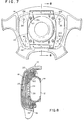
- the module housing 14 has a base plane portion 32 from which a raised concave portion 30 extends and in which the upper half of the toroidal hybrid inflator assembly 10 is positioned.
- the raised concave portion 30, as best seen in Figs. 1 and 2 is located in the center of the module housing 14 and allows the toroidal hybrid inflator assembly 12 to nest therein.
- Centrally located in the raised concave portion 30 of the module housing 14, as seen in Figs. 1 and 2 is an opening or hole 34 through which the diffuser 24 and a portion of the upper half of the toroidal hybrid inflator assembly 12 extends.
- the module housing 14 includes four spaced holes 36, 38, 40 and 44 that provide a four-point attach system for the air bag module 10, that is, for the attachment thereof to the steering wheel of an automotive or other vehicle.
- a stud, designated 44 in each case, extends downwardly through each of the holes 36, 38, 40 and 42.
- Four additional evenly spaced holes 46, 48, 50 and 52 provide a means for the attachment to the module housing 14 of the toroidal hybrid inflator assembly 12, the retaining ring 16, the inflatable cushion 18, and the retaining bracket 22.
- Eight additional smaller sized holes 54, 56, 58, 60, 62, 64, 66 and 68 are provided in the module housing 14 for the attachment thereto of the retaining ring 16 and the inflatable cushion 18.
- the module housing 14 further includes an upwardly extending wall 70 that extends completely around the periphery thereof.
- the upper edge of the wall 70 is curled outwardly forming a rolled-over lip 72, as shown in Figs. 2 and 8.
- Lip 72 engages and is locked in mating relation in a groove 74 in the side wall 76 of an inner portion 78 of the module cover 20, as best seen in Fig. 9, when the module housing 14 and the folded inflatable cushion 18 are pressed in place within the cover 20.
- the inflatable cushion 18 as illustrated in Figs. 8 and 9, has a substantially circular inflating gas inlet opening 80 with an inner periphery in a generally central region thereof.
- the diameter of the cushion gas inlet opening 80 is less than the diameter of the raised concave portion 30 immediately adjacent the base plan portion 32 of the module housing 14.
- Concave portion 30 is inserted through the cushion gas inlet opening 80 in the assembly of the air bag module 10.
- the retaining ring 16 is inserted through the gas inlet opening 80 in the cushion 18.
- the retaining ring 16, as shown in Fig. 3, has a substantial circular inner boundary and a generally rectangular outer boundary with a low inner wall 82 and a higher outer wall 84, on one side of a planar base 86, with both walls 82 and 84 being disposed substantially prependicular to the planar base 86.
- the diameter of circular inner boundary of the retaining ring 16 is substantially the same as the diameter of the concave portion 30 at the surface of the base planar portion 32 of the module housing 14.
- the planar base 86 of the retaining ring 16 also includes eight spaced downwardly extending tabs 96, 98, 100, 102, 104, 106, 108 and 110.
- the spacing of the holes 88-94 and of the tabs 96-110 is such that when the retaining ring 16 is placed in cooperating relation with the module housing 14 over the raised concave portion 30, the four holes 88-94 in the retaining ring 16 align with a respectively associated one of the four holes 46-52 in the module housing 14, and the eight tabs 96-110 in the retaining ring 16 align with a respectively associated one of the eight holes 54-68 in the module housing 14.
- Fasteners such as bolts or studs designated by reference numeral 112 and having a head at one end and threaded at the other end are inserted from the wall side of the retaining ring 16 through each of the holes 88-94.
- the retaining ring 16 is then inserted in the gas inlet opening 80 in the cushion 80 with the wall side of the retaining ring 16 facing inwardly of the cushion 18.
- the studs 112 are inserted through holes that are provided in the cushion 18 and match in position the holes 88-94 that are provided in the retaining ring 16.
- the peripheral area of the cushion 18 near the gas inlet opening is placed around the 'module housing concave portion 30 side of the inner wall 82 of the retaining ring 16.
- the eight tabs 96-110 hanging down from the retaining ring 16 match in position the eight holes 54-68 in the base plane portion 32 of the module housing 14 and extend therethrough. Tabs 96-110 extend through the holes 54-68.
- the threaded ends of the four studs 112 hang downwardly from the module housing planar base 32.
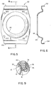
- the retaining bracket 22 as shown in Figs. 5 and 6, has a lowered concave portion 114 in which the lower or bottom half of the toroidal hybrid inflator is positioned in physically contacting relation and thereby supported, as shown in Figs. 8 and 9.
- the concave portion 114 is located in the center of the retaining bracket 22.
- Centrally located in the concave portion 114 is an opening or hole 116 through which a portion 118 of the bottom or lower half of the toroidal hybrid inflator 12 may extend.
- Four spaced holes 120, 122, 124 and 126 are provided in a base planar portion or member 128 of the retaining bracket 22.
- the spacing of the holes 120-126 is the same as the spacings of the holes 46-52 of the module housing 14 and of the holes 88-94 of the retaining ring 16.
- Clamping of the peripheral area or region of the cushion 18 near the gas inlet opening 80 thereof between the retaining ring 16 and the upper surface of the module housing planar base 32 is effected by positioning and firmly securing the retaining bracket so that the concave portion 114 thereof supports the bottom half of the hybrid inflator 12.
- Such firm securement is obtained by the application of and torquing of a nut 130 on the threaded ends of each of the four studs 112 that protrude from the holes 120-126 of the retaining bracket 22 as shown in Fig. 7.
- the manner in which the toroidal hybrid inflator 12 is clamped between the module housing 14 and the retaining bracket 22 is illustrated in Fig. 8.
- the air bag module With the peripheral region adjacent the gas inlet opening 80 of the inflatable cushion 18 clamped between the retaining ring 16 and the module housing 14, the air bag module is assembled with the toroidal hybrid inflator 12 securely attached.
- the inflatable cushion 18 can be folded prior to or after such assembly, as desired.
- the retaining bracket 22 is generally rectangular in shape.
- Cover retaining brackets 132 and 134 are incorporated, that is, formed integrally with the retaining bracket 22.
- the cover retaining brackets 132 and 134 cooperate with the module housing wall 70 and rolled over lip 72 to lock the module cover 20 in place on the air bag module 10.
- the mounting points of the air bag module 10 are located on the module housing 14 and comprise holes 36, 38, 40 and 42 which, as best seen in Figs. 1 and 7, are positioned in circular embossments 136, 138, 140 and 142, respectively. These holes facilitate the attachment by studs 44 of the air bag module 10 to the steering wheel of an automotive or other vehicle.
- the impact upon a crash or collision is detected by a sensor (not shown) which ignites a pyrotechnic heater provided in the toroidal hybrid inflator 12.
- the inflator 12 discharges inflating gas into the cushion 18 to effect rapid inflation thereof, breaking open the cover 20, which, as shown in Fig. 8, is rupturable, so that the bag can expand over the region between the steering wheel and the driver of the vehicle and thus absorb the impact on the driver.
- the clamped portion of the cushion 18 is subjected to high radial forces which tend to pull cushion 18 from the mounted position thereof.
- the engagement of the air bag gas inlet opening 80 by radial clamping provided by the inner wall 82 of the retaining ring 16 and the concave portion 30 of the module housing 14 act in opposition to those forces and retains the cushion 18 firmly in place, thus preventing gas leakage and assuring the protection of the driver.
- an air bag module for the driver side of an automtive or other vehicle in which a toroidal hybrid inflator assembly 12 of thrust neutral type is employed.
- the toroidal hybrid inflator assembly 12 is mounted in the center of the air bag module 10, being firmly held in position therewithin with the diffuser inflating gas discharge exit openings 28 thereof substantially sealed within the gas inlet opening 80 of the inflatable cushion 18 stored within the air bag module 10.
Abstract
Description
- This invention relates to an air bag module for use on the driver side of automotive and other vehicles wherein an inflatable air bag or cushion is inflated in the event of a collision to protect the driver from injury that could result from being forcibly thrown against the steering wheel, dashboard, etc. The air bag module uses a toroidal hybrid inflator assembly.
- Pyrotechnic inflator assemblies that currently are in use in driver side air bag modules, as disclosed, for example, in U.S. application for patent bearing Serial No. 07/820,826, filed January 15, 1992 by Gary V. Adams and Bradley W. Smith, typically are toroidal types having relatively flat disk-like shapes that include a flange. The modules currently produced use the flange of the toroidal inflator to attach it to the module housing.
- Inflator assemblies of the toroidal type, as disclosed in the aforementioned U.S. application for patent bearing Serial No. 07/820,826, produce a cushion inflating gas source from a combustible gas generating material which, upon ignition, generates a quantity of gas sufficient to inflate the cushion. In another form of toroidal inflator assembly, the cushion inflating gas results from a combination of stored compressed gas and a gas generating material, as disclosed, for example, in German patent Off. 2443 267 and in U.S. Patents 3,901,530 and 5,199,740. The latter form of toroidal inflator assembly is commonly referred to as a toroidal augmented gas or hybrid inflator. A toroidal hybrid inflator affects the performance of an air bag module in several ways including variation in the amount of stored gas, the transmission of heat to the stored gas, and the rate at which the inflating gas is dispensed into the inflatable cushion.
- The toroidal hybrid inflator is characterized in that it does not have a flange to attach it to the air bag module. There is thus a need and a demand to devise another method to attach the toroidal hybrid inflator to an air bag module thereby to eliminate the need for a flange to be welded thereto. The present invention was devised to fill the technological gap that has existed in the art in these respects.
- An object of the invention is to provide an air bag module for the driver side of an automotive or other vehicle which module uses a toroidal inflator assembly that is so clamped in the module that a flange is not needed, there being no change in the external appearance and function of the module and with only the internal components of the module being changed.
- Another object of the invention is to provide such an air bag module in which the toroidal inflator assembly is mounted in the center of the module.
- Still another object of the invention is to provide such an air bag module in which the toroidal inflator assembly is of the augmented gas or hybrid type.
- A further object of the invention is to provide such an air bag module in which the toroidal hybrid inflator assembly is held very firmly in position within the air bag module during the life of the module.
- Another object of the invention is to provide such an air bag module in which the inflating gas discharge exit openings of the toroidal hybrid inflator assembly are substantially sealed within the inflating gas inlet opening of the inflatable cushion stored in folded condition within the air bag module.
- An additional object of the invention is to provide such an air bag module in which the toroidal hybrid inflator assembly is of the "thrust neutral" type in which the gas discharge openings are so positioned that upon initiation of the inflator assembly the gas is discharged in opposing directions whereby there are not resulting forces tending to cause movement of the inflator assembly.
- In accomplishing these and other objectives of the invention, there is provided, in cooperative relation with a toroidal inflator assembly having no flange to attach it to an air bag module, a different housing and retaining bracket than that used in current designs to assemble a driver side air bag module. The external appearance and function of the driver side air bag module according to the invention are not changed insofar as it would be of any concern to the purchaser of an automotive or other vehicle in which such air bag module is installed. Only the internal components of the air bag module are changed.
- In a preferred embodiment of the invention, the tubular inflator assembly is a hybrid type, a pressure vessel including a storage chamber that is filled and pressurized with an inert gas such as Argon or Nitrogen to a pressure typically in the range of 2000-4000 psi. The storage chamber is defined a toroidal container. A pyrotechnic heater typically is centrally positioned in sealing relation in the storage chamber from the bottom of the container. A diffuser protrudes, that is, projects outwardly from the upper surface of the container at a central location thereof. Provided in the diffuser are a plurality of gas exit ports or orifices for dispensing inflating gas uniformly in opposing directions in a thrust neutral manner from the pressurized chamber.
- The toroidal hybrid inflator assembly is partially positioned in a concave raised portion of the module housing. This raised portion is located substantially in the center of the housing and, closely matching the upper body portion contour of the toroidal hybrid inflator, allows the inflator to nest in the housing. The diffuser of the inflator protrudes through a hole in the center of the raised portion of the module housing into the area or space where the air bag or cushion would be packed. The contour of the raised portion of the module housing closely matches the inflator and normally would be half as deep as the inflator is thick. If the inflator needs to be moved into the module more to reduce the envelope size, the raised portion of the housing is made larger to accommodate the inflator.
- The cushion retaining ring in the air bag module for clamping the inflatable cushion to the module housing and the toroidal inflator assembly is the same type of rivetless retaining ring that is used in air bag modules of current design. The retaining ring encircles the raised concave portion of the housing.
- The cushion used in the module according to the preferred embodiment of the invention is the same as that which is currently used in driver side air bag modules. Fasteners such as studs or bolts, which have been pressed into the retaining ring, also extend through the fabric of the cushion, the module housing, and a retaining bracket. The module is held together with nuts on the studs or bolts.
- The retaining bracket has a concave lowered portion in it to support the lower or bottom half of the toroidal hybrid inflator assembly and to hold it in place. The lowered concave portion closely matches the bottom contour of the inflator. Module cover retaining brackets are incorporated in the retaining bracket so that it is a unitary member or system instead of three pieces. The radius of the downward concave portion of the retaining bracket is made such that, when nuts on the studs that hold the air bag module together, are drawn down, the toroidal hybrid inflator assembly is held very firmly in position and will be so held during the life of the air bag module.
- The attach or mounting points of the air bag module for the attachment thereof to the steering wheel of an automotive or other vehicle are located on the module housing. The mounting arrangement for the module assembly may comprise a two-point attachment or a four-point attachment as needed.
- The various features of novelty which characterize the invention are pointed out with particularity in the claims annexed to and forming a part of this specification. For a better understanding of the invention, its operating advantages, and specific objects attained by its use, reference is made to the accompanying drawings and descriptive matter in which a preferred embodiment of the invention is illustrated.
- With this summary of the invention, a detailed description follows with reference being made to the accompanying drawings which form part of the specification, of which:
- Fig. 1 is a top view of the module housing of the air bag module according to the invention;
- Fig. 2 is a sectional view of the module housing of the air bag module taken along the lines 2-2 of Fig. 1;
- Fig. 3 is a top plan view of the cushion retaining ring;
- Fig. 4 is a sectional view of the cushion matching ring taken along the lines 4-4 of Fig. 3;
- Fig. 5 is a bottom view of the retaining bracket;
- Fig. 6 is a sectional view of the retaining bracket taken along the lines 6-6 of Fig. 5;
- Fig. 7 is a bottom view of the air bag module assembly;
- Fig. 8 is a sectional view of the air bag module assembly taken along the lines 8-8 of Fig. 7; and
- Fig. 9 is an enlarged view of a portion of Fig. 8 showing the inflatable cushion extending along the raised portion of the module housing.
- Referring to the figures of drawing, an
air bag module 10 according to the invention comprises a toroidalhybrid inflator assembly 12, amodule housing 14, acushion retaining ring 16, a foldedinflatable cushion 18 formed of a suitable air bag fabric, amodule cover 20, and aretaining bracket 22. - The toroidal
hybrid inflator assembly 12, as shown in Fig. 8, does not have a flange and includes a shortcylindrical diffuser 24. Thediffuser 24 protrudes outwardly from the inflator assembly exteriorupper surface 26. A plurality of gas exit ports ororifices 28 facing in different directions in substantially the same plane in the cylindrical wall of thediffuser 24 dispense inflating gas in a thrust neutral manner. Thus, upon initiation of the toroidalhybrid inflator assembly 12 and the flow of gas throughports 28 there are no forces that tend to cause disruptive movement of thetoroidal inflator assembly 12 in theair bag module 10. - The
module housing 14 has abase plane portion 32 from which a raisedconcave portion 30 extends and in which the upper half of the toroidalhybrid inflator assembly 10 is positioned. The raisedconcave portion 30, as best seen in Figs. 1 and 2, is located in the center of themodule housing 14 and allows the toroidalhybrid inflator assembly 12 to nest therein. Centrally located in the raisedconcave portion 30 of themodule housing 14, as seen in Figs. 1 and 2, is an opening orhole 34 through which thediffuser 24 and a portion of the upper half of the toroidalhybrid inflator assembly 12 extends. - The
module housing 14 includes four spacedholes air bag module 10, that is, for the attachment thereof to the steering wheel of an automotive or other vehicle. A stud, designated 44 in each case, extends downwardly through each of theholes holes module housing 14 of the toroidalhybrid inflator assembly 12, theretaining ring 16, theinflatable cushion 18, and theretaining bracket 22. Eight additional smallersized holes module housing 14 for the attachment thereto of the retainingring 16 and theinflatable cushion 18. - The
module housing 14 further includes an upwardly extendingwall 70 that extends completely around the periphery thereof. The upper edge of thewall 70 is curled outwardly forming a rolled-overlip 72, as shown in Figs. 2 and 8.Lip 72 engages and is locked in mating relation in agroove 74 in theside wall 76 of aninner portion 78 of themodule cover 20, as best seen in Fig. 9, when themodule housing 14 and the foldedinflatable cushion 18 are pressed in place within thecover 20. - The
inflatable cushion 18 as illustrated in Figs. 8 and 9, has a substantially circular inflating gas inlet opening 80 with an inner periphery in a generally central region thereof. The diameter of the cushion gas inlet opening 80 is less than the diameter of the raisedconcave portion 30 immediately adjacent thebase plan portion 32 of themodule housing 14.Concave portion 30 is inserted through the cushion gas inlet opening 80 in the assembly of theair bag module 10. - For effecting the attachment of the
inflatable cushion 18 to themodule housing 14, the retainingring 16 is inserted through the gas inlet opening 80 in thecushion 18. The retainingring 16, as shown in Fig. 3, has a substantial circular inner boundary and a generally rectangular outer boundary with a lowinner wall 82 and a higherouter wall 84, on one side of aplanar base 86, with bothwalls planar base 86. The diameter of circular inner boundary of the retainingring 16 is substantially the same as the diameter of theconcave portion 30 at the surface of the baseplanar portion 32 of themodule housing 14. - Four spaced
holes planar base 86. Theplanar base 86 of the retainingring 16 also includes eight spaced downwardly extendingtabs ring 16 is placed in cooperating relation with themodule housing 14 over the raisedconcave portion 30, the four holes 88-94 in the retainingring 16 align with a respectively associated one of the four holes 46-52 in themodule housing 14, and the eight tabs 96-110 in the retainingring 16 align with a respectively associated one of the eight holes 54-68 in themodule housing 14. - Fasteners such as bolts or studs designated by
reference numeral 112 and having a head at one end and threaded at the other end are inserted from the wall side of the retainingring 16 through each of the holes 88-94. The retainingring 16 is then inserted in the gas inlet opening 80 in thecushion 80 with the wall side of the retainingring 16 facing inwardly of thecushion 18. Thestuds 112 are inserted through holes that are provided in thecushion 18 and match in position the holes 88-94 that are provided in the retainingring 16. The peripheral area of thecushion 18 near the gas inlet opening is placed around the 'module housingconcave portion 30 side of theinner wall 82 of the retainingring 16. With the retainingring 16 so positioned relatively to the upper side of themodule housing 14, the eight tabs 96-110 hanging down from the retainingring 16 match in position the eight holes 54-68 in thebase plane portion 32 of themodule housing 14 and extend therethrough. Tabs 96-110 extend through the holes 54-68. The threaded ends of the fourstuds 112 hang downwardly from the module housingplanar base 32. - As shown in Fig. 9, with the module housing
concave portion 30 extended through theopening 80 of theinflatable cushion 18, and with the side of the retainingring 16 opposite thewalls cushion 18 against the upper surface of thebase plane portion 32 of themodule housing 14, a portion of the peripheral region of thecushion 18 near the gas inlet opening 80 extends along and is pressed against the surface of the module housing concave wall. - The retaining
bracket 22, as shown in Figs. 5 and 6, has a loweredconcave portion 114 in which the lower or bottom half of the toroidal hybrid inflator is positioned in physically contacting relation and thereby supported, as shown in Figs. 8 and 9. Theconcave portion 114 is located in the center of the retainingbracket 22. Centrally located in theconcave portion 114 is an opening orhole 116 through which aportion 118 of the bottom or lower half of thetoroidal hybrid inflator 12 may extend. Four spacedholes bracket 22. The spacing of the holes 120-126 is the same as the spacings of the holes 46-52 of themodule housing 14 and of the holes 88-94 of the retainingring 16. Thus, when the retainingbracket 22 is placed in a cooperative relation with respect to themodule housing 14 with thebottom half portion 118 of thetoroidal hybrid inflator 12 extending through thehole 116 of the retaining bracketconcave portion 114, the four holes 120-126 of the retainingbracket 22 are in alignment with the four holes 46-52 of themodule housing 14 and the four holes 88-94 of the retainingring 16. - Clamping of the peripheral area or region of the
cushion 18 near the gas inlet opening 80 thereof between the retainingring 16 and the upper surface of the module housingplanar base 32 is effected by positioning and firmly securing the retaining bracket so that theconcave portion 114 thereof supports the bottom half of thehybrid inflator 12. Such firm securement is obtained by the application of and torquing of anut 130 on the threaded ends of each of the fourstuds 112 that protrude from the holes 120-126 of the retainingbracket 22 as shown in Fig. 7. The manner in which thetoroidal hybrid inflator 12 is clamped between themodule housing 14 and the retainingbracket 22 is illustrated in Fig. 8.
With the peripheral region adjacent the gas inlet opening 80 of theinflatable cushion 18 clamped between the retainingring 16 and themodule housing 14, the air bag module is assembled with thetoroidal hybrid inflator 12 securely attached. Theinflatable cushion 18 can be folded prior to or after such assembly, as desired. - As shown in Figs. 5 and 6, the retaining
bracket 22 is generally rectangular in shape. Cover retainingbrackets bracket 22. Thecover retaining brackets module housing wall 70 and rolled overlip 72 to lock themodule cover 20 in place on theair bag module 10. - The mounting points of the
air bag module 10 are located on themodule housing 14 and compriseholes circular embossments studs 44 of theair bag module 10 to the steering wheel of an automotive or other vehicle. - In the operation of the
air bag module 10, the impact upon a crash or collision is detected by a sensor (not shown) which ignites a pyrotechnic heater provided in thetoroidal hybrid inflator 12. The inflator 12 discharges inflating gas into thecushion 18 to effect rapid inflation thereof, breaking open thecover 20, which, as shown in Fig. 8, is rupturable, so that the bag can expand over the region between the steering wheel and the driver of the vehicle and thus absorb the impact on the driver. At this time the clamped portion of thecushion 18 is subjected to high radial forces which tend to pullcushion 18 from the mounted position thereof. However, the engagement of the air bag gas inlet opening 80 by radial clamping provided by theinner wall 82 of the retainingring 16 and theconcave portion 30 of themodule housing 14 act in opposition to those forces and retains thecushion 18 firmly in place, thus preventing gas leakage and assuring the protection of the driver. - Thus, in accordance with the invention, there has been provided an air bag module for the driver side of an automtive or other vehicle in which a toroidal
hybrid inflator assembly 12 of thrust neutral type is employed. The toroidalhybrid inflator assembly 12 is mounted in the center of theair bag module 10, being firmly held in position therewithin with the diffuser inflating gasdischarge exit openings 28 thereof substantially sealed within the gas inlet opening 80 of theinflatable cushion 18 stored within theair bag module 10. - Although the invention has been described in an application in which the
air bag module 10 is mounted to a steering wheel for the protection of the driver, those skilled in the art will understand that the air bag module can be mounted to the dashboard or some other part of the body of the vehicle. Those skilled in the art will understand also that although the invention has been described as involving toroidal hybrid inflators that it is applicable also for use with other toroidal inflators having no flange. - With this description of the invention in detail, those skilled in the art will appreciate that modifications may be made to the invention without departing from the spirit thereof, Therefore, it is not intended that the scope of the invention be limited to the specific embodiments that have been illustrated and described. Rather, it is intended that the scope of the invention be determined by the appended claims and their equivalents.
Claims (12)
- A vehicle air bag module (10) comprising:
a module housing (14) including a planar base portion (32) having a generally centrally located raised concave portion (30) and an upwardly extending wall (70) that extends substantially around the periphery thereof, said concave portion (30) having a substantially centrally located hole (34) provided therein,
a generally circular inflator (12) having a first half and a second half with a diffuser (24) provided at an outer portion of the first half of said inflator, the first half of said inflator (12) being so contoured and physically positioned as to nest in said raised concave portion (30) of said module housing (14) with said diffuser (24) adjacent said hole provided in said concave portion (30),
a retaining bracket (22) including a base planar portion having a generally centrally located concave portion (114) with a hole (116) therein, which concave portion (114) extends around a portion at least of said inflator (12) with said base planar portion thereof positioned adjacent said base planar portion (32) of said module housing (14), and
means to clamp the base planar portion of said retaining bracket (22) towards the base planar portion (32) of said module housing (14) thereby to clamp said inflator (12) to said module housing (14). - A vehicle air bag module (10) as claimed in claim 1,
wherein the size of the hole (116) in said retaining bracket (22) is such as to allow a portion of the second half of said inflator (12) to extend therethrough when the base planar portions of said retaining bracket (22) and of said module housing (14) are clamped towards each other. - A vehicle air bag module as claimed in claim 1 or 2 further including:
an inflatable cushion (18) formed of a suitable air bag fabric and having a gas inlet opening (80) with an inner peripheral region formed therein, and
a retaining ring (16) having a substantially circular inner boundary and an outer boundary with a low inner wall (82) and a higher outer wall (84) on one side and a planar base portion (86) with both walls being disposed substantially perpendicular to the planar base thereof, with the diameter of said circular inner boundary being substantially the same as the diameter of said module housing concave portion (30) at the base plane portion (32) thereof, said retaining ring (16) being positioned in said gas inlet opening (80) of said cushion (18) with the wall side thereof facing inwardly and extending around the inner peripheral region thereof, said retaining ring (16) being positioned in cooperative relation with said module housing (14) around said concave portion (30) thereof,
wherein said means to clamp the base planar portion of said retaining bracket (22) towards the base planar portion (32) of said module housing (14) also clamps the planar base portion (86) of said retaining ring (16) and a portion at least of the inner peripheral region of said cushion (18) to the planar base portion (32) of said module housing (14). - A vehicle air bag module (10) as claimed in claim 3,
wherein the planar base portion (32) of said module housing (14) includes a plurality of spaced holes (56, 58 ...) therein, and
wherein said retaining ring (16) includes a plurality of tabs (98, 100, ...) extending in spaced relation from the surface of the planar base portion (86) thereof that is opposite to the surface from which said walls (82, 84) extend, said tabs (98, 100, ...) being so positioned on said retaining ring (16) that they align with and extend through some at least of said plurality of holes (56, 58, ...) in the planar base portion (32) of said module housing (14). - A vehicle air bag module (10) as claimed in claim 3 or 4,
wherein the peripheral region of said cushion (18) and each of the base planar portions of said module housing (14), said retaining ring (16) and said retaining bracket (22) include holes (46, 88, 120, ...) that are all in alignment, and
wherein said means to clamp the base planar portions of said retaining ring (16) and said retaining bracket (22) to the base planar portion (32) of said module housing (14) comprise a plurality of fasteners (112) which extend through said holes in said cushion (18) and said base planar portions that are in alignment, each of which fasteners has a head at one end and is threaded at the other end with each of the heads positioned in engagement with the wall side of said retaining ring (16), and a nut (130) screwed on and tightened on the threaded end of each fastener (112). - A vehicle air bag module (10) as claimed in claim 3, 4 or 5,
wherein said inflatable cushion (18) is folded, and
wherein a distal edge of said outer wall (84) of said module housing (14) is curled outwardly forming a rolled over lip (72), the module further including
a cover (20) for an inflatable cushion (18) and module housing (14), said cover (20) including a groove (74) in a side wall (76) of an inner portion (78) thereof,
whereby said rolled over lip (72) on said module housing outer wall (70) engages and is locked in mating relation in said groove (74) in the side wall (76) of the inner portion (78) of said cover (20) when said module housing (14) and cushion (18) are pressed in place within said cover (20). - A vehicle air bag module (10) as claimed in claim 6,
wherein said retaining bracket includes cover retaining brackets (132, 134) that are formed integrally therewith and are positioned in engagement with said side wall (76) of said cover (20) and thereby cooperate with said module housing (14) and rolled over lip (72) to lock said cover (20) in place on said air bag module (10). - A vehicle air bag module (10) as claimed in any one of claims 3 to 7,
wherein the opening in said inflatable cushion (18) is substantially circular and has a diameter less than the diameter of the raised concave portion (30) of said module housing (14) at the base plane member portion (32) thereof,
whereby when said module housing concave portion (32) is extended through said opening and the side of said retaining ring (16) opposite said walls (82, 84) thereof is brought towards or into engagement with an upper surface of the base plane portion (32) of said module housing (14), a portion at least of said peripheral region of said cushion (18) near said gas inlet opening thereof extends along and in engagement with the surface of the module housing raised concave portion (30). - A vehicle air bag module (10) as claimed in any preceding claim, wherein said base planar portion of said retaining bracket (22) is clamped against said base planar portion (32) of said module housing (14).
- A vehicle air bag module (10) as claimed in any preceding claim, wherein said diffuser (24) extends through said hole (34) in said concave portion (30) of said module housing (14).
- A vehicle air bag module (10) as claimed in any preceding claim, wherein said inflator (12) is a toroidal inflator.
- A vehicle air bag module (10) as claimed in any preceding claim, wherein said concave portion (114) of said retaining bracket (22) physically contacts a portion at least of said inflator (12).
Applications Claiming Priority (2)
| Application Number | Priority Date | Filing Date | Title |
|---|---|---|---|
| US136355 | 1993-10-14 | ||
| US08/136,355 US5425548A (en) | 1993-10-14 | 1993-10-14 | Air bag module with a centrally mounted toroidal inflator using a clamshell inflator retention system |
Publications (2)
| Publication Number | Publication Date |
|---|---|
| EP0648649A2 true EP0648649A2 (en) | 1995-04-19 |
| EP0648649A3 EP0648649A3 (en) | 1995-09-06 |
Family
ID=22472480
Family Applications (1)
| Application Number | Title | Priority Date | Filing Date |
|---|---|---|---|
| EP94307446A Ceased EP0648649A3 (en) | 1993-10-14 | 1994-10-11 | Air bag module with a centrally mounted inflator using a clamshell inflator retention system. |
Country Status (4)
| Country | Link |
|---|---|
| US (1) | US5425548A (en) |
| EP (1) | EP0648649A3 (en) |
| JP (1) | JP2603807B2 (en) |
| CA (1) | CA2127333A1 (en) |
Cited By (1)
| Publication number | Priority date | Publication date | Assignee | Title |
|---|---|---|---|---|
| EP1024061A2 (en) * | 1999-01-26 | 2000-08-02 | TRW Automotive Safety Systems GmbH & Co. KG | Connection between inflator retainer and cover in an air bag module |
Families Citing this family (14)
| Publication number | Priority date | Publication date | Assignee | Title |
|---|---|---|---|---|
| US5577763A (en) * | 1995-03-29 | 1996-11-26 | Trw Inc. | Air bag mounting structure and method |
| US5931491A (en) * | 1997-08-28 | 1999-08-03 | Autoliv Asp, Inc. | Airbag module with a reduced number of fasteners |
| JP4560881B2 (en) | 2000-04-21 | 2010-10-13 | タカタ株式会社 | Airbag device |
| US6746042B2 (en) * | 2001-01-15 | 2004-06-08 | Trw Occupant Restraint Systems Gmbh & Co. Kg | Vehicle interior lining and method of producing a vehicle interior lining |
| US6702318B2 (en) * | 2001-04-11 | 2004-03-09 | Autoliv Asp, Inc. | Vehicle occupant restraint module with disk inflator |
| DE10150275A1 (en) * | 2001-10-12 | 2003-04-17 | Zf Lemfoerder Metallwaren Ag | Housing for inflatable airbag has gas generator fixed inside diffuser by form-locking and/or mechanically locking connection with inner wall of diffuser chamber |
| JP4364081B2 (en) * | 2004-07-14 | 2009-11-11 | 豊田合成株式会社 | Airbag device |
| US7630067B2 (en) | 2004-11-30 | 2009-12-08 | Molecular Imprints, Inc. | Interferometric analysis method for the manufacture of nano-scale devices |
| US8052167B2 (en) * | 2007-06-22 | 2011-11-08 | Tk Holdings Inc. | Airbag assembly |
| JP6215646B2 (en) | 2013-10-22 | 2017-10-18 | 株式会社ダイセル | Inflator and airbag fixing structure |
| US9682679B2 (en) * | 2014-08-08 | 2017-06-20 | Autoliv Asp, Inc. | Airbag inflator retainers and related methods and systems |
| US9573549B2 (en) | 2015-06-30 | 2017-02-21 | Autoliv Asp, Inc. | Inflator device with integral clamp stop |
| JP6951182B2 (en) * | 2016-12-16 | 2021-10-20 | 株式会社ダイセル | Retainer and gas generator |
| WO2018110350A1 (en) * | 2016-12-16 | 2018-06-21 | 株式会社ダイセル | Retainer and gas generator |
Citations (5)
| Publication number | Priority date | Publication date | Assignee | Title |
|---|---|---|---|---|
| FR2256056A1 (en) * | 1974-01-02 | 1975-07-25 | Eaton Corp | Power supply system for inflatable gas bag - has chamber for compressed gas valve system and combustible material heater |
| US4913461A (en) * | 1988-12-27 | 1990-04-03 | Talley Automotive Products, Inc. | Airbag module and method of making same |
| US4915410A (en) * | 1988-11-28 | 1990-04-10 | Trw Vehicle Safety Systems Inc. | Vehicle air bag module and method of assembly |
| US5186490A (en) * | 1991-09-23 | 1993-02-16 | Morton International, Inc. | Driver cover integral horn switch with solid reinforcement structure |
| US5209519A (en) * | 1990-06-18 | 1993-05-11 | Honda Giken Kogyo Kabushiki Kaisha | Vehicle occupant protection air bag module |
Family Cites Families (7)
| Publication number | Priority date | Publication date | Assignee | Title |
|---|---|---|---|---|
| US3901530A (en) * | 1973-08-08 | 1975-08-26 | Allied Chem | Multiple mini hybrid with direct bag connection |
| JPS5076735A (en) * | 1973-09-14 | 1975-06-23 | ||
| US4013010A (en) * | 1974-11-04 | 1977-03-22 | Thiokol Corporation | Gas generator with expandable cartridge |
| JPH02164640A (en) * | 1988-12-19 | 1990-06-25 | Takata Kk | Air bag device |
| US5199740A (en) * | 1991-06-10 | 1993-04-06 | Bendix Atlantic Inflator Co. | Hybrid inflator for air bag |
| US5314203A (en) * | 1992-01-15 | 1994-05-24 | Morton International, Inc. | Driver-side module attach bracket |
| US5290059A (en) * | 1993-04-28 | 1994-03-01 | Morton International, Inc. | Air bag module with a center mounted tubular inflator |
-
1993
- 1993-10-14 US US08/136,355 patent/US5425548A/en not_active Expired - Fee Related
-
1994
- 1994-07-04 CA CA002127333A patent/CA2127333A1/en not_active Abandoned
- 1994-07-13 JP JP6161044A patent/JP2603807B2/en not_active Expired - Fee Related
- 1994-10-11 EP EP94307446A patent/EP0648649A3/en not_active Ceased
Patent Citations (5)
| Publication number | Priority date | Publication date | Assignee | Title |
|---|---|---|---|---|
| FR2256056A1 (en) * | 1974-01-02 | 1975-07-25 | Eaton Corp | Power supply system for inflatable gas bag - has chamber for compressed gas valve system and combustible material heater |
| US4915410A (en) * | 1988-11-28 | 1990-04-10 | Trw Vehicle Safety Systems Inc. | Vehicle air bag module and method of assembly |
| US4913461A (en) * | 1988-12-27 | 1990-04-03 | Talley Automotive Products, Inc. | Airbag module and method of making same |
| US5209519A (en) * | 1990-06-18 | 1993-05-11 | Honda Giken Kogyo Kabushiki Kaisha | Vehicle occupant protection air bag module |
| US5186490A (en) * | 1991-09-23 | 1993-02-16 | Morton International, Inc. | Driver cover integral horn switch with solid reinforcement structure |
Cited By (2)
| Publication number | Priority date | Publication date | Assignee | Title |
|---|---|---|---|---|
| EP1024061A2 (en) * | 1999-01-26 | 2000-08-02 | TRW Automotive Safety Systems GmbH & Co. KG | Connection between inflator retainer and cover in an air bag module |
| EP1024061A3 (en) * | 1999-01-26 | 2001-02-14 | TRW Automotive Safety Systems GmbH & Co. KG | Connection between inflator retainer and cover in an air bag module |
Also Published As
| Publication number | Publication date |
|---|---|
| JP2603807B2 (en) | 1997-04-23 |
| EP0648649A3 (en) | 1995-09-06 |
| CA2127333A1 (en) | 1995-04-15 |
| US5425548A (en) | 1995-06-20 |
| JPH07117611A (en) | 1995-05-09 |
Similar Documents
| Publication | Publication Date | Title |
|---|---|---|
| US5290059A (en) | Air bag module with a center mounted tubular inflator | |
| JP2721719B2 (en) | Airbag module and its assembly method | |
| US5425548A (en) | Air bag module with a centrally mounted toroidal inflator using a clamshell inflator retention system | |
| US5458364A (en) | Inflator secured in diffuser housing of airbag module assembly by locking end cap | |
| US5470105A (en) | Diffuser device and incorporation thereof in an inflatable restraint system | |
| JP2604972B2 (en) | Apparatus and method for attaching inflatable cushion to reaction vessel member | |
| EP1150867B1 (en) | Driver side airbag module | |
| US6854760B2 (en) | Cylindrical passenger airbag module | |
| EP0558240A1 (en) | Continuous circumference diffuser reaction canister | |
| US5275431A (en) | Air bag inflator assembly | |
| US5685558A (en) | Air bag inflator mounting | |
| US5788266A (en) | Simplified airbag module housing | |
| US5520409A (en) | Cover retention in occupant restraint installations | |
| US5762360A (en) | Air bag assembly | |
| US5441299A (en) | Air bag inflator subassembly for installation onto the dashboard substrate of a motor vehicle | |
| US5511818A (en) | Passenger side airbag module | |
| US5498024A (en) | Inflatable restraint assembly | |
| EP0714816B1 (en) | Deployment door for use in a vehicle occupant restraint apparatus | |
| JPH09104314A (en) | Attachment method of mounting bracket to air bag inflator | |
| EP0668196B1 (en) | Vehicle occupant restraint apparatus | |
| US5470102A (en) | Air bag module with an off-center mounted tubular inflator | |
| US5799969A (en) | Vehicle occupant protection apparatus | |
| US5836607A (en) | Gas generator attachment means for a vehicle safety apparatus | |
| US5458363A (en) | Cylindrical inflator retainer ring | |
| US5449195A (en) | Constant diameter inflator retainer |
Legal Events
| Date | Code | Title | Description |
|---|---|---|---|
| PUAI | Public reference made under article 153(3) epc to a published international application that has entered the european phase |
Free format text: ORIGINAL CODE: 0009012 |
|
| AK | Designated contracting states |
Kind code of ref document: A2 Designated state(s): BE DE ES FR GB IT NL SE |
|
| PUAL | Search report despatched |
Free format text: ORIGINAL CODE: 0009013 |
|
| AK | Designated contracting states |
Kind code of ref document: A3 Designated state(s): BE DE ES FR GB IT NL SE |
|
| 17P | Request for examination filed |
Effective date: 19960217 |
|
| GRAG | Despatch of communication of intention to grant |
Free format text: ORIGINAL CODE: EPIDOS AGRA |
|
| 17Q | First examination report despatched |
Effective date: 19980618 |
|
| STAA | Information on the status of an ep patent application or granted ep patent |
Free format text: STATUS: THE APPLICATION HAS BEEN REFUSED |
|
| 18R | Application refused |
Effective date: 19981205 |