EP0650077A1 - Surface illuminant - Google Patents
Surface illuminant Download PDFInfo
- Publication number
- EP0650077A1 EP0650077A1 EP94914591A EP94914591A EP0650077A1 EP 0650077 A1 EP0650077 A1 EP 0650077A1 EP 94914591 A EP94914591 A EP 94914591A EP 94914591 A EP94914591 A EP 94914591A EP 0650077 A1 EP0650077 A1 EP 0650077A1
- Authority
- EP
- European Patent Office
- Prior art keywords
- light
- light source
- prism sheet
- source device
- conducting member
- Prior art date
- Legal status (The legal status is an assumption and is not a legal conclusion. Google has not performed a legal analysis and makes no representation as to the accuracy of the status listed.)
- Granted
Links
Images

Classifications
-
- G—PHYSICS
- G02—OPTICS
- G02B—OPTICAL ELEMENTS, SYSTEMS OR APPARATUS
- G02B6/00—Light guides; Structural details of arrangements comprising light guides and other optical elements, e.g. couplings
- G02B6/0001—Light guides; Structural details of arrangements comprising light guides and other optical elements, e.g. couplings specially adapted for lighting devices or systems
- G02B6/0011—Light guides; Structural details of arrangements comprising light guides and other optical elements, e.g. couplings specially adapted for lighting devices or systems the light guides being planar or of plate-like form
- G02B6/0033—Means for improving the coupling-out of light from the light guide
- G02B6/005—Means for improving the coupling-out of light from the light guide provided by one optical element, or plurality thereof, placed on the light output side of the light guide
- G02B6/0053—Prismatic sheet or layer; Brightness enhancement element, sheet or layer
-
- G—PHYSICS
- G02—OPTICS
- G02B—OPTICAL ELEMENTS, SYSTEMS OR APPARATUS
- G02B5/00—Optical elements other than lenses
- G02B5/02—Diffusing elements; Afocal elements
- G02B5/0205—Diffusing elements; Afocal elements characterised by the diffusing properties
- G02B5/021—Diffusing elements; Afocal elements characterised by the diffusing properties the diffusion taking place at the element's surface, e.g. by means of surface roughening or microprismatic structures
- G02B5/0231—Diffusing elements; Afocal elements characterised by the diffusing properties the diffusion taking place at the element's surface, e.g. by means of surface roughening or microprismatic structures the surface having microprismatic or micropyramidal shape
-
- G—PHYSICS
- G02—OPTICS
- G02F—OPTICAL DEVICES OR ARRANGEMENTS FOR THE CONTROL OF LIGHT BY MODIFICATION OF THE OPTICAL PROPERTIES OF THE MEDIA OF THE ELEMENTS INVOLVED THEREIN; NON-LINEAR OPTICS; FREQUENCY-CHANGING OF LIGHT; OPTICAL LOGIC ELEMENTS; OPTICAL ANALOGUE/DIGITAL CONVERTERS
- G02F1/00—Devices or arrangements for the control of the intensity, colour, phase, polarisation or direction of light arriving from an independent light source, e.g. switching, gating or modulating; Non-linear optics
- G02F1/01—Devices or arrangements for the control of the intensity, colour, phase, polarisation or direction of light arriving from an independent light source, e.g. switching, gating or modulating; Non-linear optics for the control of the intensity, phase, polarisation or colour
- G02F1/13—Devices or arrangements for the control of the intensity, colour, phase, polarisation or direction of light arriving from an independent light source, e.g. switching, gating or modulating; Non-linear optics for the control of the intensity, phase, polarisation or colour based on liquid crystals, e.g. single liquid crystal display cells
- G02F1/133—Constructional arrangements; Operation of liquid crystal cells; Circuit arrangements
- G02F1/1333—Constructional arrangements; Manufacturing methods
- G02F1/1335—Structural association of cells with optical devices, e.g. polarisers or reflectors
- G02F1/1336—Illuminating devices
- G02F1/133615—Edge-illuminating devices, i.e. illuminating from the side
-
- G—PHYSICS
- G02—OPTICS
- G02B—OPTICAL ELEMENTS, SYSTEMS OR APPARATUS
- G02B6/00—Light guides; Structural details of arrangements comprising light guides and other optical elements, e.g. couplings
- G02B6/0001—Light guides; Structural details of arrangements comprising light guides and other optical elements, e.g. couplings specially adapted for lighting devices or systems
-
- G—PHYSICS
- G02—OPTICS
- G02F—OPTICAL DEVICES OR ARRANGEMENTS FOR THE CONTROL OF LIGHT BY MODIFICATION OF THE OPTICAL PROPERTIES OF THE MEDIA OF THE ELEMENTS INVOLVED THEREIN; NON-LINEAR OPTICS; FREQUENCY-CHANGING OF LIGHT; OPTICAL LOGIC ELEMENTS; OPTICAL ANALOGUE/DIGITAL CONVERTERS
- G02F1/00—Devices or arrangements for the control of the intensity, colour, phase, polarisation or direction of light arriving from an independent light source, e.g. switching, gating or modulating; Non-linear optics
- G02F1/01—Devices or arrangements for the control of the intensity, colour, phase, polarisation or direction of light arriving from an independent light source, e.g. switching, gating or modulating; Non-linear optics for the control of the intensity, phase, polarisation or colour
- G02F1/13—Devices or arrangements for the control of the intensity, colour, phase, polarisation or direction of light arriving from an independent light source, e.g. switching, gating or modulating; Non-linear optics for the control of the intensity, phase, polarisation or colour based on liquid crystals, e.g. single liquid crystal display cells
- G02F1/133—Constructional arrangements; Operation of liquid crystal cells; Circuit arrangements
- G02F1/1333—Constructional arrangements; Manufacturing methods
- G02F1/1335—Structural association of cells with optical devices, e.g. polarisers or reflectors
- G02F1/1336—Illuminating devices
- G02F1/133602—Direct backlight
- G02F1/133606—Direct backlight including a specially adapted diffusing, scattering or light controlling members
- G02F1/133607—Direct backlight including a specially adapted diffusing, scattering or light controlling members the light controlling member including light directing or refracting elements, e.g. prisms or lenses
Definitions
- the present invention relates to a surface light source device for use in a back light system of a liquid crystal display apparatus.
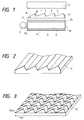
- Fig. 6 shows a construction of a liquid crystal display apparatus in which a conventional surface light source device using a light conducting member is used as its back light system.
- the numerical reference 1 represents a plate-like light conducting member, which is made of a transparent material
- 2 a linear light source disposed in the vicinity of a light emitting edge surface 1a of said light conducting member 1
- 3 a light diffusing plate disposed on a front surface 1b of said light conducting member 1
- the numerical reference 4 represents a light reflecting member arranged on a rear surface 1c of said light conducting member, constituting of the surface light source device.
- the numerical reference 5 represents a liquid crystal display apparatus.
- a light emitted from the light source 2 is made incident upon the light emitting surface 1a of the light conducting member 1 and then the light is introduced inside thereof.
- the light is transmitted to an opposite edge surface 1d of the light conducting member, the light is emitted from the front surface (light emitting surface) 1b of the light conducting member and then passes through the light diffusing plate 3 to become a diffused light.
- the liquid crystal display apparatus 5 is illuminated by the diffused light coming from the light diffusing plate 3.
- the illuminating light generated from the surface light source device is diffused in all directions by the light diffusing plate 3, but the most of them is directed to a direction shown by arrows in Fig. 6. Therefore, there exists some light which is not made incident upon the liquid crystal display apparatus, and thus enough brightness cannot be obtained on the apparatus. Further, out of the light being made incident upon the liquid crystal display apparatus, only a few light is directed to a direction substantially perpendicular to the liquid crystal display apparatus, because of the existence of the light diffusion plate 3. Therefore, there is a drawback that the image surface of the liquid crystal display apparatus is dark for an operator who observes the image surface in front of the liquid crystal display apparatus.
- a prism sheet 11 on the surface of which a multiplicity of prism-like portions are formed, is disposed between the light diffusing plate 3 and the liquid crystal display apparatus 5, and thereby the diffusing light emitted from the light diffusing plate 3 is directed to a direction which is perpendicular to the surface of the liquid crystal display apparatus.
- a prism sheet 11 on the surface of which a multiplicity of prism-like portions are formed, is disposed between the light diffusing plate 3 and the liquid crystal display apparatus 5, and thereby the diffusing light emitted from the light diffusing plate 3 is directed to a direction which is perpendicular to the surface of the liquid crystal display apparatus.
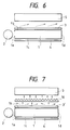
- a light diffusing plate 3' having a strong light diffusing power is used as shown in Fig. 7.
- the light coming through the light diffusing plate 3' is diffused into directions shown by the arrows in an enough manner, so that it can be prevented that the large amount of the diffusing light is directed into a perspective direction as shown in Fig. 6.
- the present invention has its object to provide a surface light source device using a light conducting member, particularly a surface light source device having a highly qualified brightness, by which an observation can be carried out on a bright image surface when the surface light source device according to the present invention is used as a back light system of a liquid crystal display apparatus.
- a surface light source device comprises a light conducting member, a linear light source disposed in the vicinity of a light emitting edge surface of the light conducting member, a light diffusing member having a comparatively weak light diffusing power disposed on a front surface of the light conducting member, a light reflecting member disposed on a rear surface of the light conducting member, and a prism sheet disposed on one side of the light diffusing member which is opposite to the side on which the light conducting member is arranged; wherein the prism sheet comprises a multiplicity of prisms on a surface thereof, and each of prism has its cross section, which is in a direction perpendicular to both the light incident edge surface and the front surface of the light conducting member, such that an angle of the cross section on the light incident edge surface side is smaller than an angle on an opposite side thereof.
- the prism sheet having such a construction By using the prism sheet having such a construction, the light diffused by the light diffusing member, which is directed in a perspective direction as a whole so as to be separated from the light source, is forced to change its direction into an upper direction. And thus, the brightness of the surface light source device becomes much higher.
- any kind of shape of the prism sheet may be possible to use in the device according to the present invention and the same effect can be obtained.
- Fig. 1 is a cross-sectional view showing a liquid crystal display apparatus in which an embodiment of the surface light source device according to the present invention is used; and Fig. 2 is a perspective view illustrating a part of the prism sheet which is used in the first embodiment of the surface light source device.
- the numerical reference 1 represents a light conducting member
- 2 a linear light source
- 3 a light diffusing plate
- 4 represents a light reflecting member.
- the surface light source device has the same construction as those of the devices shown in Figs. 6 and 7.
- the numerical reference 5 denotes a liquid crystal display apparatus.
- a prism sheet 11 having a construction which is different from the prism sheet 10 shown in Fig. 7 is disposed between the light diffusing plate 3 and the liquid crystal display apparatus 5.
- the prism sheet 11 has a saw-teeth like convex portions as shown in Fig. 2; that is to say, in a cross section thereof, which is cut in a direction perpendicular to both a light incident edge surface 1a and a front surface 1b of the light conducting member 1 (the cross section illustrated in Fig. 2, which is viewed from the direction shown by the arrow), there are provided a multiplicity of triangles in an orderly manner. It should be noted that the angles A and B of each triangle are arranged in such a manner that angle A on the light source side (a light incident edge surface side) is smaller than the angle B on the opposite side.
- the diffusing light emitted from the light diffusing plate 3 as a whole is firstly directed to a direction as shown in Fig. 6, but the direction is changed to an upper direction by the function of prisms provided on the prism sheet. Then, the diffusing light is made incident upon the liquid crystal display apparatus 5.
- the function of prisms the most of the diffusing light is directed to a direction which is perpendicular or substantially perpendicular to the prism sheet, so that a bright back light system for the liquid crystal display apparatus, for instance, can be obtained.
- Fig. 3 shows a construction of the second embodiment of the prism sheet.
- the prism sheet 12 comprises prisms each of which has a quadrangle pyramid shape, in which an inclined angle of a surface 12a, which is arranged on a light source side, is smaller than that of an opposite surface 12b.
- the prism sheet 12 comprising quadrangle pyramid shaped prisms gets the same function of the prism sheet 11, and thus the same effect can be obtained.
- Fig. 4 is a perspective view showing a construction of the third embodiment of the prism sheet 13.
- the prism sheet 13 comprises a multiplicity of conical shaped prisms, in which the top of each prisms is directed to an opposite side of the light source a little. Further, the prisms are arranged in such a manner that an angle corresponding to the angle A of the prism sheet of the second embodiment, which is shown in Fig. 2, is smaller than an angle corresponding to the angle B of the prism sheet of the second embodiment.
- Fig. 5 is a perspective view representing the prism sheet used in the third embodiment of the surface light source device.
- the prism sheet 14 comprises a multiplicity of prisms each having a quadrangle pyramid shape but without its top portion. Therefore, each of the prism has a trapezoid-like cross section. Further, the inclined angle of the inclined surface 14a of the prism is arranged to be smaller than the inclined angle of the inclined surface 14b, and thus the prism sheet has the same function and effect as those of the prism sheet of the second embodiment.
- the prism sheets may have some shapes other than the above-mentioned embodiments (prism sheets may have prisms having the shapes other than those of the embodiments, including the prisms whose corner portions, i.e. apical angle portions or edge portions thereof, are rounded off), and the prism sheets have the same function and effect as those of the above-mentioned embodiments, if only the prisms formed on the prism sheet are arranged such that the angle on the light source side is smaller than the angle on the opposite side.
- the angle A is less than 45° degrees and the angle B is between 35° to 60° degrees. That is to say, the angles A and B are desired to satisfy the following conditions.
- a ⁇ 45° 35° ⁇ B ⁇ 60° A ⁇ B In the above mentioned embodiments, the surface light source device comprising only one linear light source is shown. However, the present invention can be applied to the surface light source device having two or more linear light sources. For instance, the present invention may be applied to the surface light source device having two linear light sources which is obtained by adding one more linear light source on the edge surface 1d side of the light conducting member of the device shown in Fig. 1.
- the prism sheet should have its construction such that the prisms formed on the edge surface 1d side of the prism sheet are arranged to be inclined in a direction, which is reversed to the direction in which the prisms formed on the edge surface 1a side of the prism sheet are inclined.
- the prism sheets piled in an upper side from the second one may be possible to be designed such that the inclined angles of the prisms formed on the edge surface 1a side and the edge surface 1d side are the same.
- the prism sheet having special shaped prisms is arranged on the surface of the light diffusing plate so that the most of the light emitted from the prism sheet is directed to a direction perpendicular or substantially perpendicular to the surface of the prism sheet. Therefore, when the surface light source device according to the present invention is used, for instance, as a back light system of the liquid crystal display apparatus, a bright light source can be obtained.
Abstract
Description
- The present invention relates to a surface light source device for use in a back light system of a liquid crystal display apparatus.
- Fig. 6 shows a construction of a liquid crystal display apparatus in which a conventional surface light source device using a light conducting member is used as its back light system. In Fig. 6, the
numerical reference 1 represents a plate-like light conducting member, which is made of a transparent material, 2 a linear light source disposed in the vicinity of a light emittingedge surface 1a of saidlight conducting member 1, 3 a light diffusing plate disposed on afront surface 1b of saidlight conducting member 1 and thenumerical reference 4 represents a light reflecting member arranged on arear surface 1c of said light conducting member, constituting of the surface light source device. Further, thenumerical reference 5 represents a liquid crystal display apparatus. - In the surface light source device, a light emitted from the
light source 2 is made incident upon thelight emitting surface 1a of thelight conducting member 1 and then the light is introduced inside thereof. During when the light is transmitted to anopposite edge surface 1d of the light conducting member, the light is emitted from the front surface (light emitting surface) 1b of the light conducting member and then passes through thelight diffusing plate 3 to become a diffused light. The liquidcrystal display apparatus 5 is illuminated by the diffused light coming from thelight diffusing plate 3. - The illuminating light generated from the surface light source device is diffused in all directions by the
light diffusing plate 3, but the most of them is directed to a direction shown by arrows in Fig. 6. Therefore, there exists some light which is not made incident upon the liquid crystal display apparatus, and thus enough brightness cannot be obtained on the apparatus. Further, out of the light being made incident upon the liquid crystal display apparatus, only a few light is directed to a direction substantially perpendicular to the liquid crystal display apparatus, because of the existence of thelight diffusion plate 3. Therefore, there is a drawback that the image surface of the liquid crystal display apparatus is dark for an operator who observes the image surface in front of the liquid crystal display apparatus. - In order to dissolve the drawback, it is considered that a
prism sheet 11, on the surface of which a multiplicity of prism-like portions are formed, is disposed between the light diffusingplate 3 and the liquidcrystal display apparatus 5, and thereby the diffusing light emitted from thelight diffusing plate 3 is directed to a direction which is perpendicular to the surface of the liquid crystal display apparatus. However, an enough effect cannot be still obtained by using such prism sheet having the prism-like portions, which are formed thereon in a symmetrical manner. - Further, it is also considered that a light diffusing plate 3' having a strong light diffusing power is used as shown in Fig. 7. In such a device, the light coming through the light diffusing plate 3' is diffused into directions shown by the arrows in an enough manner, so that it can be prevented that the large amount of the diffusing light is directed into a perspective direction as shown in Fig. 6.
- However, in this device, since the light diffusing function is strong, the light directed in a perpendicular direction with respect to the light diffusing plate is relatively decreased, too. Therefore, the problem cannot be improved that the brightness is not enough for the operator who observes the image surface in front of the liquid crystal display apparatus. In this case, even if the
prism sheet 10 is arranged in the device, it is impossible to increase the brightness thereof. - The present invention has its object to provide a surface light source device using a light conducting member, particularly a surface light source device having a highly qualified brightness, by which an observation can be carried out on a bright image surface when the surface light source device according to the present invention is used as a back light system of a liquid crystal display apparatus.
- A surface light source device according to the present invention comprises a light conducting member, a linear light source disposed in the vicinity of a light emitting edge surface of the light conducting member, a light diffusing member having a comparatively weak light diffusing power disposed on a front surface of the light conducting member, a light reflecting member disposed on a rear surface of the light conducting member, and a prism sheet disposed on one side of the light diffusing member which is opposite to the side on which the light conducting member is arranged; wherein the prism sheet comprises a multiplicity of prisms on a surface thereof, and each of prism has its cross section, which is in a direction perpendicular to both the light incident edge surface and the front surface of the light conducting member, such that an angle of the cross section on the light incident edge surface side is smaller than an angle on an opposite side thereof. By using the prism sheet having such a construction, the light diffused by the light diffusing member, which is directed in a perspective direction as a whole so as to be separated from the light source, is forced to change its direction into an upper direction. And thus, the brightness of the surface light source device becomes much higher.
- It should be noted that unless the prism-like convex portions formed on the prism sheet are designed such that the angle on the light incident edge surface side is smaller than the angle on the opposite side thereof in the above mentioned cross section, any kind of shape of the prism sheet may be possible to use in the device according to the present invention and the same effect can be obtained.
-
- Fig. 1 is a cross-sectional view showing a construction of the first embodiment of the surface light source device according to the present invention;
- Fig. 2 is a perspective view depicting a construction of the prism sheet which is used in the first embodiment according to the present invention;
- Fig. 3 is a perspective view illustrating a construction of the prism sheet which is used in the second embodiment according to the present invention;
- Fig. 4 is a perspective view representing a construction of the prism sheet which is used in the third embodiment according to the present invention;
- Fig. 5 is a perspective view showing a construction of the prism sheet which is used in the fourth embodiment according tot he present invention;
- Fig. 6 is a cross-sectional view depicting a construction of the conventional surface light source device; and
- Fig. 7 is a cross sectional view illustrating a construction of another conventional surface light source device.
- The embodiments of the surface light source device according to the present invention will be explained in the following. Fig. 1 is a cross-sectional view showing a liquid crystal display apparatus in which an embodiment of the surface light source device according to the present invention is used; and Fig. 2 is a perspective view illustrating a part of the prism sheet which is used in the first embodiment of the surface light source device. In these figures, the
numerical reference 1 represents a light conducting member, 2 a linear light source, 3 a light diffusing plate, and thenumerical reference 4 represents a light reflecting member. It should be noted that the surface light source device has the same construction as those of the devices shown in Figs. 6 and 7. Thenumerical reference 5 denotes a liquid crystal display apparatus. In this embodiment, aprism sheet 11 having a construction which is different from theprism sheet 10 shown in Fig. 7 is disposed between the light diffusingplate 3 and the liquidcrystal display apparatus 5. Theprism sheet 11 has a saw-teeth like convex portions as shown in Fig. 2; that is to say, in a cross section thereof, which is cut in a direction perpendicular to both a lightincident edge surface 1a and afront surface 1b of the light conducting member 1 (the cross section illustrated in Fig. 2, which is viewed from the direction shown by the arrow), there are provided a multiplicity of triangles in an orderly manner. It should be noted that the angles A and B of each triangle are arranged in such a manner that angle A on the light source side (a light incident edge surface side) is smaller than the angle B on the opposite side. - According to the embodiment, the diffusing light emitted from the
light diffusing plate 3 as a whole is firstly directed to a direction as shown in Fig. 6, but the direction is changed to an upper direction by the function of prisms provided on the prism sheet. Then, the diffusing light is made incident upon the liquidcrystal display apparatus 5. By the function of prisms, the most of the diffusing light is directed to a direction which is perpendicular or substantially perpendicular to the prism sheet, so that a bright back light system for the liquid crystal display apparatus, for instance, can be obtained. - Fig. 3 shows a construction of the second embodiment of the prism sheet. The
prism sheet 12 comprises prisms each of which has a quadrangle pyramid shape, in which an inclined angle of a surface 12a, which is arranged on a light source side, is smaller than that of an opposite surface 12b. Such a construction, theprism sheet 12 comprising quadrangle pyramid shaped prisms gets the same function of theprism sheet 11, and thus the same effect can be obtained. - Fig. 4 is a perspective view showing a construction of the third embodiment of the
prism sheet 13. Theprism sheet 13 comprises a multiplicity of conical shaped prisms, in which the top of each prisms is directed to an opposite side of the light source a little. Further, the prisms are arranged in such a manner that an angle corresponding to the angle A of the prism sheet of the second embodiment, which is shown in Fig. 2, is smaller than an angle corresponding to the angle B of the prism sheet of the second embodiment. - Fig. 5 is a perspective view representing the prism sheet used in the third embodiment of the surface light source device. The
prism sheet 14 comprises a multiplicity of prisms each having a quadrangle pyramid shape but without its top portion. Therefore, each of the prism has a trapezoid-like cross section. Further, the inclined angle of theinclined surface 14a of the prism is arranged to be smaller than the inclined angle of theinclined surface 14b, and thus the prism sheet has the same function and effect as those of the prism sheet of the second embodiment. - In the embodiments mentioned in the above, typical shapes of the convex portions (prism portions) formed on the prism sheet are shown. However, the prism sheets may have some shapes other than the above-mentioned embodiments (prism sheets may have prisms having the shapes other than those of the embodiments, including the prisms whose corner portions, i.e. apical angle portions or edge portions thereof, are rounded off), and the prism sheets have the same function and effect as those of the above-mentioned embodiments, if only the prisms formed on the prism sheet are arranged such that the angle on the light source side is smaller than the angle on the opposite side.
- It is desired that the angle A is less than 45° degrees and the angle B is between 35° to 60° degrees. That is to say, the angles A and B are desired to satisfy the following conditions.
A ≦ 45°
35°≦ B ≦ 60°
A < B
In the above mentioned embodiments, the surface light source device comprising only one linear light source is shown. However, the present invention can be applied to the surface light source device having two or more linear light sources. For instance, the present invention may be applied to the surface light source device having two linear light sources which is obtained by adding one more linear light source on theedge surface 1d side of the light conducting member of the device shown in Fig. 1. In this case, the prism sheet should have its construction such that the prisms formed on theedge surface 1d side of the prism sheet are arranged to be inclined in a direction, which is reversed to the direction in which the prisms formed on theedge surface 1a side of the prism sheet are inclined. (This means in theedge surface 1d side of the prism sheet the smaller angle A should be arranged on theedge surface 1d side and the larger angle B on theedge surface 1a side); and thus the direction of the prisms should be changed at the center of the prism sheet, i.e. between theedge surface 1a and theedge surface 1d. Irrespective of the number of light sources provided in the device, it may be possible to arrange a plurality of piled-up prism sheets in the device. In this case, the prism sheets piled in an upper side from the second one may be possible to be designed such that the inclined angles of the prisms formed on theedge surface 1a side and theedge surface 1d side are the same. - In the surface light source device according to the present invention, the prism sheet having special shaped prisms is arranged on the surface of the light diffusing plate so that the most of the light emitted from the prism sheet is directed to a direction perpendicular or substantially perpendicular to the surface of the prism sheet. Therefore, when the surface light source device according to the present invention is used, for instance, as a back light system of the liquid crystal display apparatus, a bright light source can be obtained.
Claims (8)
- A surface light source device comprising a light conducting member; a linear light source being disposed in the vicinity of at least one of light emitting edge surfaces of said light conducting member; a light diffusing member being disposed on a front surface side of said light conducting member; a light reflecting member being disposed on a rear surface of said light conducting member; and a prism sheet being disposed on one side of said light diffusing member, which is opposite to the side where the light conducting member is arranged, and having a multiplicity of prism-like convex portions on at least one of surfaces of the prism sheet; wherein each convex portion of said prism sheet is arranged such that an inclined angle on a light source side is smaller than an inclined angle on an opposite side thereof in a cross-section of the prism sheet which is cut in a direction perpendicular to both an light incident edge surface and a front surface of said light conducting member.
- A surface light source device according to Claim 1, wherein said light source is arranged only one of the edge side surfaces of the light conducting member.
- A surface light source device according to Claim 2, wherein said surface light source device satisfies the following conditions:
A ≦ 45°
35° ≦ B ≦ 60°
A < B
wherein the reference symbol A represents an angle at a light source side of said convex portion of the prism sheet, and the reference symbol B denotes an angle at an opposite side of the light source side of said convex portion. - A surface light source device according to Claim 1, 2 or 3, wherein the convex portions of said prism sheet form a saw-teeth like shape cross section, when the prism sheet is cut in a direction perpendicular to both the light emitting edge surface and the front surface of the light conducting member; and the saw-teeth like convex portions are extended in a perpendicular direction with respect to the cross section.
- A surface light source device according to C;claim 1, 2 or 3, wherein each of the convex portion of said prism sheet has a quadrangle pyramid shape.
- A surface light source device according to Claim 1, 2 or 3, wherein each of the convex portion of said prism sheet has a conical shape.
- A surface light source device according to Claim 1, 2,or 3, wherein each of the convex portions of said prism sheet has a quadrangle pyramid shape without its top portion and thus has its cross section of trapezoid.
- A surface light source device according to Claim 1, 2 or 3, wherein each of the convex portion of the prism sheet has a conical or polygonal pyramid shape with a rounded top portion.
Applications Claiming Priority (4)
| Application Number | Priority Date | Filing Date | Title |
|---|---|---|---|
| JP2899393U | 1993-05-07 | ||
| JP28993/93U | 1993-05-07 | ||
| JP1993028993U JP2599121Y2 (en) | 1993-05-07 | 1993-05-07 | Surface light source device |
| PCT/JP1994/000743 WO1994027171A1 (en) | 1993-05-07 | 1994-05-06 | Surface illuminant |
Publications (3)
| Publication Number | Publication Date |
|---|---|
| EP0650077A1 true EP0650077A1 (en) | 1995-04-26 |
| EP0650077A4 EP0650077A4 (en) | 1995-12-06 |
| EP0650077B1 EP0650077B1 (en) | 1999-11-17 |
Family
ID=12263945
Family Applications (1)
| Application Number | Title | Priority Date | Filing Date |
|---|---|---|---|
| EP94914591A Expired - Lifetime EP0650077B1 (en) | 1993-05-07 | 1994-05-06 | Surface illuminant |
Country Status (5)
| Country | Link |
|---|---|
| US (1) | US5572411A (en) |
| EP (1) | EP0650077B1 (en) |
| JP (1) | JP2599121Y2 (en) |
| DE (1) | DE69421668T2 (en) |
| WO (1) | WO1994027171A1 (en) |
Cited By (6)
| Publication number | Priority date | Publication date | Assignee | Title |
|---|---|---|---|---|
| WO2006121690A1 (en) * | 2005-05-05 | 2006-11-16 | 3M Innovative Properties Company | Optical film having a surface with rounded pyramidal structures |
| US7220026B2 (en) | 2004-12-30 | 2007-05-22 | 3M Innovative Properties Company | Optical film having a structured surface with offset prismatic structures |
| WO2007110543A1 (en) * | 2006-03-27 | 2007-10-04 | Saint-Gobain Glass France | Diffusing structure |
| US7320538B2 (en) | 2004-12-30 | 2008-01-22 | 3M Innovative Properties Company | Optical film having a structured surface with concave pyramid-shaped structures |
| US7416309B2 (en) | 2004-12-30 | 2008-08-26 | 3M Innovative Properties Company | Optical film having a surface with rounded structures |
| EP2184628A3 (en) * | 2008-11-06 | 2010-10-06 | CEAG Notlichtsysteme GmbH | Lights, in particular emergency, rescue or safety lights |
Families Citing this family (49)
| Publication number | Priority date | Publication date | Assignee | Title |
|---|---|---|---|---|
| DE69432353T2 (en) * | 1993-11-05 | 2003-11-20 | Enplas Corp | AREA LIGHT SOURCE |
| JP2742880B2 (en) * | 1994-08-12 | 1998-04-22 | 大日本印刷株式会社 | Surface light source, display device using the same, and light diffusion sheet used for them |
| US5657408A (en) * | 1994-12-23 | 1997-08-12 | Alliedsignal Inc. | Optical device comprising a plurality of units having at least two geometrically-differentiated tapered optical waveguides therein |
| JP3548812B2 (en) * | 1995-08-11 | 2004-07-28 | オムロン株式会社 | Surface light source device, planar optical element used in the device, and image display device using the device |
| JPH09274184A (en) * | 1996-04-04 | 1997-10-21 | Dainippon Printing Co Ltd | Lens film and surface light source device using it |
| JPH10105087A (en) * | 1996-09-30 | 1998-04-24 | Sony Corp | Flat display |
| DE69841612D1 (en) * | 1997-02-13 | 2010-05-27 | Honeywell Int Inc | LIGHTING SYSTEM WITH REUSE OF LIGHT TO INCREASE BRIGHTNESS |
| US6123431A (en) * | 1997-03-19 | 2000-09-26 | Sanyo Electric Co., Ltd | Backlight apparatus and light guide plate |
| JP3615355B2 (en) * | 1997-06-04 | 2005-02-02 | 株式会社エンプラス | Sidelight type surface light source device and light guide plate |
| US6752505B2 (en) * | 1999-02-23 | 2004-06-22 | Solid State Opto Limited | Light redirecting films and film systems |
| US6590711B1 (en) * | 2000-04-03 | 2003-07-08 | 3M Innovative Properties Co. | Light directing construction having corrosion resistant feature |
| US6264336B1 (en) | 1999-10-22 | 2001-07-24 | 3M Innovative Properties Company | Display apparatus with corrosion-resistant light directing film |
| KR20030096509A (en) * | 2002-06-12 | 2003-12-31 | 삼성전자주식회사 | Prism sheet and lcd having the same |
| TW547670U (en) * | 2002-11-08 | 2003-08-11 | Hon Hai Prec Ind Co Ltd | Backlight system and its light guide plate |
| JP2005055481A (en) * | 2003-06-09 | 2005-03-03 | Toyota Industries Corp | Optical element, planar illumination apparatus and display apparatus |
| KR100717499B1 (en) * | 2003-11-12 | 2007-05-14 | 엘지전자 주식회사 | Prism sheet, back light assembly and display device |
| JP2006086075A (en) * | 2004-09-17 | 2006-03-30 | Alps Electric Co Ltd | Surface-emitting device, back surface-lighting system and liquid crystal display |
| KR100660707B1 (en) * | 2004-11-18 | 2006-12-21 | 엘지전자 주식회사 | backlight unit |
| JP4789175B2 (en) * | 2005-02-25 | 2011-10-12 | 株式会社エンプラス | Surface light source device and display device |
| JP4645256B2 (en) * | 2005-03-25 | 2011-03-09 | ソニー株式会社 | Electro-optical device and electronic apparatus |
| JP4693556B2 (en) * | 2005-09-02 | 2011-06-01 | シャープ株式会社 | Liquid crystal display |
| TWI315432B (en) * | 2005-11-21 | 2009-10-01 | Optoma Corp | Brightness enhancement film and backlight module |
| US7674028B2 (en) | 2006-01-13 | 2010-03-09 | Avery Dennison Corporation | Light enhancing structures with multiple arrays of elongate features of varying characteristics |
| US7866871B2 (en) | 2006-01-13 | 2011-01-11 | Avery Dennison Corporation | Light enhancing structures with a plurality of arrays of elongate features |
| US7366393B2 (en) | 2006-01-13 | 2008-04-29 | Optical Research Associates | Light enhancing structures with three or more arrays of elongate features |
| CN101025452A (en) * | 2006-02-17 | 2007-08-29 | 鸿富锦精密工业(深圳)有限公司 | Optical sheet and backlight module using same |
| CN101025518A (en) * | 2006-02-25 | 2007-08-29 | 鸿富锦精密工业(深圳)有限公司 | Optical sheet |
| US20080062704A1 (en) * | 2006-09-08 | 2008-03-13 | Yu-Wei Chang | High uniformity diffuser lens structure |
| US20110241977A1 (en) * | 2010-04-01 | 2011-10-06 | Microsoft Corporation | Enhanced viewing brightness for surface display |
| US9625638B2 (en) | 2013-03-15 | 2017-04-18 | Cree, Inc. | Optical waveguide body |
| US9581751B2 (en) | 2013-01-30 | 2017-02-28 | Cree, Inc. | Optical waveguide and lamp including same |
| US9869432B2 (en) | 2013-01-30 | 2018-01-16 | Cree, Inc. | Luminaires using waveguide bodies and optical elements |
| US9690029B2 (en) | 2013-01-30 | 2017-06-27 | Cree, Inc. | Optical waveguides and luminaires incorporating same |
| US9366396B2 (en) | 2013-01-30 | 2016-06-14 | Cree, Inc. | Optical waveguide and lamp including same |
| US9442243B2 (en) | 2013-01-30 | 2016-09-13 | Cree, Inc. | Waveguide bodies including redirection features and methods of producing same |
| US9291320B2 (en) | 2013-01-30 | 2016-03-22 | Cree, Inc. | Consolidated troffer |
| US10436970B2 (en) | 2013-03-15 | 2019-10-08 | Ideal Industries Lighting Llc | Shaped optical waveguide bodies |
| US10209429B2 (en) | 2013-03-15 | 2019-02-19 | Cree, Inc. | Luminaire with selectable luminous intensity pattern |
| US10379278B2 (en) * | 2013-03-15 | 2019-08-13 | Ideal Industries Lighting Llc | Outdoor and/or enclosed structure LED luminaire outdoor and/or enclosed structure LED luminaire having outward illumination |
| US9366799B2 (en) | 2013-03-15 | 2016-06-14 | Cree, Inc. | Optical waveguide bodies and luminaires utilizing same |
| US9920901B2 (en) | 2013-03-15 | 2018-03-20 | Cree, Inc. | LED lensing arrangement |
| US10502899B2 (en) * | 2013-03-15 | 2019-12-10 | Ideal Industries Lighting Llc | Outdoor and/or enclosed structure LED luminaire |
| US9798072B2 (en) | 2013-03-15 | 2017-10-24 | Cree, Inc. | Optical element and method of forming an optical element |
| US10400984B2 (en) | 2013-03-15 | 2019-09-03 | Cree, Inc. | LED light fixture and unitary optic member therefor |
| US9645303B2 (en) | 2013-03-15 | 2017-05-09 | Cree, Inc. | Luminaires utilizing edge coupling |
| US10416377B2 (en) | 2016-05-06 | 2019-09-17 | Cree, Inc. | Luminaire with controllable light emission |
| US11719882B2 (en) | 2016-05-06 | 2023-08-08 | Ideal Industries Lighting Llc | Waveguide-based light sources with dynamic beam shaping |
| US10739513B2 (en) | 2018-08-31 | 2020-08-11 | RAB Lighting Inc. | Apparatuses and methods for efficiently directing light toward and away from a mounting surface |
| US10801679B2 (en) | 2018-10-08 | 2020-10-13 | RAB Lighting Inc. | Apparatuses and methods for assembling luminaires |
Citations (1)
| Publication number | Priority date | Publication date | Assignee | Title |
|---|---|---|---|---|
| EP0531939A1 (en) * | 1991-09-09 | 1993-03-17 | Enplas Corporation | Surface light source device |
Family Cites Families (6)
| Publication number | Priority date | Publication date | Assignee | Title |
|---|---|---|---|---|
| US4791540A (en) * | 1987-05-26 | 1988-12-13 | Minnesota Mining And Manufacturing Company | Light fixture providing normalized output |
| DE3872084T2 (en) * | 1987-06-29 | 1992-12-03 | Japan Engine Valve Mfg | DRAWING APPARATUS. |
| JPH0727137B2 (en) * | 1988-06-02 | 1995-03-29 | 三菱レイヨン株式会社 | Surface light source element |
| JPH0533129A (en) * | 1991-07-30 | 1993-02-09 | Hitachi Metals Ltd | Ti-w target material |
| JPH0533129U (en) * | 1991-10-09 | 1993-04-30 | 住友化学工業株式会社 | Surface light source |
| JP2692025B2 (en) * | 1992-01-24 | 1997-12-17 | スタンレー電気株式会社 | Planar light emitter device |
-
1993
- 1993-05-07 JP JP1993028993U patent/JP2599121Y2/en not_active Expired - Lifetime
-
1994
- 1994-05-06 WO PCT/JP1994/000743 patent/WO1994027171A1/en active IP Right Grant
- 1994-05-06 DE DE69421668T patent/DE69421668T2/en not_active Expired - Fee Related
- 1994-05-06 EP EP94914591A patent/EP0650077B1/en not_active Expired - Lifetime
- 1994-05-06 US US08/362,446 patent/US5572411A/en not_active Expired - Lifetime
Patent Citations (1)
| Publication number | Priority date | Publication date | Assignee | Title |
|---|---|---|---|---|
| EP0531939A1 (en) * | 1991-09-09 | 1993-03-17 | Enplas Corporation | Surface light source device |
Non-Patent Citations (1)
| Title |
|---|
| See also references of WO9427171A1 * |
Cited By (6)
| Publication number | Priority date | Publication date | Assignee | Title |
|---|---|---|---|---|
| US7220026B2 (en) | 2004-12-30 | 2007-05-22 | 3M Innovative Properties Company | Optical film having a structured surface with offset prismatic structures |
| US7320538B2 (en) | 2004-12-30 | 2008-01-22 | 3M Innovative Properties Company | Optical film having a structured surface with concave pyramid-shaped structures |
| US7416309B2 (en) | 2004-12-30 | 2008-08-26 | 3M Innovative Properties Company | Optical film having a surface with rounded structures |
| WO2006121690A1 (en) * | 2005-05-05 | 2006-11-16 | 3M Innovative Properties Company | Optical film having a surface with rounded pyramidal structures |
| WO2007110543A1 (en) * | 2006-03-27 | 2007-10-04 | Saint-Gobain Glass France | Diffusing structure |
| EP2184628A3 (en) * | 2008-11-06 | 2010-10-06 | CEAG Notlichtsysteme GmbH | Lights, in particular emergency, rescue or safety lights |
Also Published As
| Publication number | Publication date |
|---|---|
| DE69421668D1 (en) | 1999-12-23 |
| US5572411A (en) | 1996-11-05 |
| JP2599121Y2 (en) | 1999-08-30 |
| EP0650077A4 (en) | 1995-12-06 |
| DE69421668T2 (en) | 2000-03-02 |
| JPH0687936U (en) | 1994-12-22 |
| WO1994027171A1 (en) | 1994-11-24 |
| EP0650077B1 (en) | 1999-11-17 |
Similar Documents
| Publication | Publication Date | Title |
|---|---|---|
| US5572411A (en) | Surface light source device | |
| US6155692A (en) | Surface light source device of side light type | |
| US5600455A (en) | Prismatic member with coarsened portions or triangular prismatic and semi-circular prismatic members arranged on a flat light emitting surface | |
| US6174064B1 (en) | Light guide panel and plane illuminator apparatus | |
| JP3615355B2 (en) | Sidelight type surface light source device and light guide plate | |
| KR100723857B1 (en) | Light guide plate, surface light source device, and display device | |
| US6402335B1 (en) | Light guide panel and plane illuminator apparatus | |
| JP3543911B2 (en) | Sidelight type surface light source device | |
| JP3736724B2 (en) | Light guide plate, side light type surface light source device, and liquid crystal display device | |
| US20070165419A1 (en) | Spread illuminating apparatus having light reflecting sheet with light diffusing portions | |
| JP2004200072A (en) | Flat lighting device | |
| JP2002196151A (en) | Light guide plate | |
| EP0531939A1 (en) | Surface light source device | |
| KR20060061257A (en) | Surface light source device and display device | |
| JP3588180B2 (en) | Light control member and side light type surface light source device | |
| EP3486560A1 (en) | Display device | |
| JPH0915426A (en) | Light guiding plate and surface type lighting body using the light guiding plate | |
| JPH10319242A (en) | Light guide plate | |
| JP2003123525A (en) | Surface light source device, image display device and light guide plate | |
| JPH09292531A (en) | Light transmission plate, optical deflecting plate and surface illuminator | |
| JP2000100229A (en) | Light guiding plate, side light type surface light source device and liquid crystal display device | |
| JP2590227Y2 (en) | Surface light source device | |
| JPH095529A (en) | Light transmission plate and surface type illuminating body using the same | |
| JP2005315924A (en) | Face light source device, image display device, and luminous flux controlling plate | |
| JP4329926B2 (en) | Surface light source device, image display device, and light guide plate |
Legal Events
| Date | Code | Title | Description |
|---|---|---|---|
| PUAI | Public reference made under article 153(3) epc to a published international application that has entered the european phase |
Free format text: ORIGINAL CODE: 0009012 |
|
| 17P | Request for examination filed |
Effective date: 19950102 |
|
| AK | Designated contracting states |
Kind code of ref document: A1 Designated state(s): DE FR GB IT NL |
|
| A4 | Supplementary search report drawn up and despatched | ||
| AK | Designated contracting states |
Kind code of ref document: A4 Designated state(s): DE FR GB IT NL |
|
| 17Q | First examination report despatched |
Effective date: 19980805 |
|
| GRAG | Despatch of communication of intention to grant |
Free format text: ORIGINAL CODE: EPIDOS AGRA |
|
| GRAG | Despatch of communication of intention to grant |
Free format text: ORIGINAL CODE: EPIDOS AGRA |
|
| GRAH | Despatch of communication of intention to grant a patent |
Free format text: ORIGINAL CODE: EPIDOS IGRA |
|
| GRAH | Despatch of communication of intention to grant a patent |
Free format text: ORIGINAL CODE: EPIDOS IGRA |
|
| GRAA | (expected) grant |
Free format text: ORIGINAL CODE: 0009210 |
|
| AK | Designated contracting states |
Kind code of ref document: B1 Designated state(s): DE FR GB IT NL |
|
| ITF | It: translation for a ep patent filed |
Owner name: JACOBACCI & PERANI S.P.A. |
|
| REF | Corresponds to: |
Ref document number: 69421668 Country of ref document: DE Date of ref document: 19991223 |
|
| ET | Fr: translation filed | ||
| PLBE | No opposition filed within time limit |
Free format text: ORIGINAL CODE: 0009261 |
|
| STAA | Information on the status of an ep patent application or granted ep patent |
Free format text: STATUS: NO OPPOSITION FILED WITHIN TIME LIMIT |
|
| 26N | No opposition filed | ||
| REG | Reference to a national code |
Ref country code: GB Ref legal event code: IF02 |
|
| PGFP | Annual fee paid to national office [announced via postgrant information from national office to epo] |
Ref country code: NL Payment date: 20060515 Year of fee payment: 13 |
|
| PGFP | Annual fee paid to national office [announced via postgrant information from national office to epo] |
Ref country code: IT Payment date: 20070528 Year of fee payment: 14 |
|
| PG25 | Lapsed in a contracting state [announced via postgrant information from national office to epo] |
Ref country code: NL Free format text: LAPSE BECAUSE OF NON-PAYMENT OF DUE FEES Effective date: 20071201 |
|
| NLV4 | Nl: lapsed or anulled due to non-payment of the annual fee |
Effective date: 20071201 |
|
| PGFP | Annual fee paid to national office [announced via postgrant information from national office to epo] |
Ref country code: DE Payment date: 20080415 Year of fee payment: 15 |
|
| PGFP | Annual fee paid to national office [announced via postgrant information from national office to epo] |
Ref country code: GB Payment date: 20080522 Year of fee payment: 15 |
|
| PG25 | Lapsed in a contracting state [announced via postgrant information from national office to epo] |
Ref country code: IT Free format text: LAPSE BECAUSE OF NON-PAYMENT OF DUE FEES Effective date: 20080506 |
|
| GBPC | Gb: european patent ceased through non-payment of renewal fee |
Effective date: 20090506 |
|
| REG | Reference to a national code |
Ref country code: FR Ref legal event code: ST Effective date: 20100129 |
|
| PG25 | Lapsed in a contracting state [announced via postgrant information from national office to epo] |
Ref country code: FR Free format text: LAPSE BECAUSE OF NON-PAYMENT OF DUE FEES Effective date: 20090602 |
|
| PGFP | Annual fee paid to national office [announced via postgrant information from national office to epo] |
Ref country code: FR Payment date: 20080425 Year of fee payment: 15 |
|
| PG25 | Lapsed in a contracting state [announced via postgrant information from national office to epo] |
Ref country code: GB Free format text: LAPSE BECAUSE OF NON-PAYMENT OF DUE FEES Effective date: 20090506 |
|
| PG25 | Lapsed in a contracting state [announced via postgrant information from national office to epo] |
Ref country code: DE Free format text: LAPSE BECAUSE OF NON-PAYMENT OF DUE FEES Effective date: 20091201 |