EP0650079A1 - Optical compensatory sheet and liquid crystal display having the same - Google Patents
Optical compensatory sheet and liquid crystal display having the same Download PDFInfo
- Publication number
- EP0650079A1 EP0650079A1 EP94116645A EP94116645A EP0650079A1 EP 0650079 A1 EP0650079 A1 EP 0650079A1 EP 94116645 A EP94116645 A EP 94116645A EP 94116645 A EP94116645 A EP 94116645A EP 0650079 A1 EP0650079 A1 EP 0650079A1
- Authority
- EP
- European Patent Office
- Prior art keywords
- sheet
- liquid crystal
- optical compensatory
- film
- crystal display
- Prior art date
- Legal status (The legal status is an assumption and is not a legal conclusion. Google has not performed a legal analysis and makes no representation as to the accuracy of the status listed.)
- Granted
Links
- 230000003287 optical effect Effects 0.000 title claims abstract description 78
- 239000004973 liquid crystal related substance Substances 0.000 title claims abstract description 71
- 230000001447 compensatory effect Effects 0.000 title claims abstract description 62
- 210000002858 crystal cell Anatomy 0.000 claims description 19
- 239000004988 Nematic liquid crystal Substances 0.000 claims description 12
- 239000000758 substrate Substances 0.000 claims description 7
- 210000004027 cell Anatomy 0.000 claims description 3
- 229920000642 polymer Polymers 0.000 description 19
- 238000000034 method Methods 0.000 description 14
- 238000004040 coloring Methods 0.000 description 13
- 239000000126 substance Substances 0.000 description 11
- 229920006254 polymer film Polymers 0.000 description 8
- 150000001875 compounds Chemical class 0.000 description 7
- 230000002093 peripheral effect Effects 0.000 description 6
- 229910000831 Steel Inorganic materials 0.000 description 4
- 238000006317 isomerization reaction Methods 0.000 description 4
- 239000010959 steel Substances 0.000 description 4
- YMWUJEATGCHHMB-UHFFFAOYSA-N Dichloromethane Chemical compound ClCCl YMWUJEATGCHHMB-UHFFFAOYSA-N 0.000 description 3
- 239000002131 composite material Substances 0.000 description 3
- 239000011159 matrix material Substances 0.000 description 3
- -1 polyallylate Polymers 0.000 description 3
- 229920006289 polycarbonate film Polymers 0.000 description 3
- IISBACLAFKSPIT-UHFFFAOYSA-N bisphenol A Chemical compound C=1C=C(O)C=CC=1C(C)(C)C1=CC=C(O)C=C1 IISBACLAFKSPIT-UHFFFAOYSA-N 0.000 description 2
- 230000008030 elimination Effects 0.000 description 2
- 238000003379 elimination reaction Methods 0.000 description 2
- 230000001678 irradiating effect Effects 0.000 description 2
- 239000000463 material Substances 0.000 description 2
- 239000004417 polycarbonate Substances 0.000 description 2
- 229920000515 polycarbonate Polymers 0.000 description 2
- 150000003384 small molecules Chemical class 0.000 description 2
- VTWKXBJHBHYJBI-SOFGYWHQSA-N (ne)-n-benzylidenehydroxylamine Chemical class O\N=C\C1=CC=CC=C1 VTWKXBJHBHYJBI-SOFGYWHQSA-N 0.000 description 1
- 229920002284 Cellulose triacetate Polymers 0.000 description 1
- 229920006385 Geon Polymers 0.000 description 1
- YGYAWVDWMABLBF-UHFFFAOYSA-N Phosgene Chemical compound ClC(Cl)=O YGYAWVDWMABLBF-UHFFFAOYSA-N 0.000 description 1
- 239000004952 Polyamide Substances 0.000 description 1
- 239000004695 Polyether sulfone Substances 0.000 description 1
- 239000004642 Polyimide Substances 0.000 description 1
- 239000004721 Polyphenylene oxide Substances 0.000 description 1
- 239000004734 Polyphenylene sulfide Substances 0.000 description 1
- 239000004793 Polystyrene Substances 0.000 description 1
- 239000004372 Polyvinyl alcohol Substances 0.000 description 1
- 241001085205 Prenanthella exigua Species 0.000 description 1
- NNLVGZFZQQXQNW-ADJNRHBOSA-N [(2r,3r,4s,5r,6s)-4,5-diacetyloxy-3-[(2s,3r,4s,5r,6r)-3,4,5-triacetyloxy-6-(acetyloxymethyl)oxan-2-yl]oxy-6-[(2r,3r,4s,5r,6s)-4,5,6-triacetyloxy-2-(acetyloxymethyl)oxan-3-yl]oxyoxan-2-yl]methyl acetate Chemical compound O([C@@H]1O[C@@H]([C@H]([C@H](OC(C)=O)[C@H]1OC(C)=O)O[C@H]1[C@@H]([C@@H](OC(C)=O)[C@H](OC(C)=O)[C@@H](COC(C)=O)O1)OC(C)=O)COC(=O)C)[C@@H]1[C@@H](COC(C)=O)O[C@@H](OC(C)=O)[C@H](OC(C)=O)[C@H]1OC(C)=O NNLVGZFZQQXQNW-ADJNRHBOSA-N 0.000 description 1
- DMLAVOWQYNRWNQ-UHFFFAOYSA-N azobenzene Chemical class C1=CC=CC=C1N=NC1=CC=CC=C1 DMLAVOWQYNRWNQ-UHFFFAOYSA-N 0.000 description 1
- 239000006227 byproduct Substances 0.000 description 1
- 229920002678 cellulose Polymers 0.000 description 1
- 239000001913 cellulose Substances 0.000 description 1
- 150000001851 cinnamic acid derivatives Chemical class 0.000 description 1
- 229920001577 copolymer Polymers 0.000 description 1
- 230000007423 decrease Effects 0.000 description 1
- 238000011156 evaluation Methods 0.000 description 1
- 229920001519 homopolymer Polymers 0.000 description 1
- 238000004519 manufacturing process Methods 0.000 description 1
- 239000000203 mixture Substances 0.000 description 1
- 229920003229 poly(methyl methacrylate) Polymers 0.000 description 1
- 229920002492 poly(sulfone) Polymers 0.000 description 1
- 229920002239 polyacrylonitrile Polymers 0.000 description 1
- 229920002647 polyamide Polymers 0.000 description 1
- 238000006068 polycondensation reaction Methods 0.000 description 1
- 229920006393 polyether sulfone Polymers 0.000 description 1
- 239000005020 polyethylene terephthalate Substances 0.000 description 1
- 229920000139 polyethylene terephthalate Polymers 0.000 description 1
- 229920001721 polyimide Polymers 0.000 description 1
- 239000002861 polymer material Substances 0.000 description 1
- 239000004926 polymethyl methacrylate Substances 0.000 description 1
- 229920000098 polyolefin Polymers 0.000 description 1
- 229920006380 polyphenylene oxide Polymers 0.000 description 1
- 229920000069 polyphenylene sulfide Polymers 0.000 description 1
- 229920005553 polystyrene-acrylate Polymers 0.000 description 1
- 229920002451 polyvinyl alcohol Polymers 0.000 description 1
- 239000004800 polyvinyl chloride Substances 0.000 description 1
- 229920000915 polyvinyl chloride Polymers 0.000 description 1
- NCYCYZXNIZJOKI-OVSJKPMPSA-N retinal group Chemical group C\C(=C/C=O)\C=C\C=C(\C=C\C1=C(CCCC1(C)C)C)/C NCYCYZXNIZJOKI-OVSJKPMPSA-N 0.000 description 1
- PJANXHGTPQOBST-UHFFFAOYSA-N stilbene Chemical class C=1C=CC=CC=1C=CC1=CC=CC=C1 PJANXHGTPQOBST-UHFFFAOYSA-N 0.000 description 1
- 238000002834 transmittance Methods 0.000 description 1
Images


Classifications
-
- G—PHYSICS
- G02—OPTICS
- G02F—OPTICAL DEVICES OR ARRANGEMENTS FOR THE CONTROL OF LIGHT BY MODIFICATION OF THE OPTICAL PROPERTIES OF THE MEDIA OF THE ELEMENTS INVOLVED THEREIN; NON-LINEAR OPTICS; FREQUENCY-CHANGING OF LIGHT; OPTICAL LOGIC ELEMENTS; OPTICAL ANALOGUE/DIGITAL CONVERTERS
- G02F1/00—Devices or arrangements for the control of the intensity, colour, phase, polarisation or direction of light arriving from an independent light source, e.g. switching, gating or modulating; Non-linear optics
- G02F1/01—Devices or arrangements for the control of the intensity, colour, phase, polarisation or direction of light arriving from an independent light source, e.g. switching, gating or modulating; Non-linear optics for the control of the intensity, phase, polarisation or colour
- G02F1/13—Devices or arrangements for the control of the intensity, colour, phase, polarisation or direction of light arriving from an independent light source, e.g. switching, gating or modulating; Non-linear optics for the control of the intensity, phase, polarisation or colour based on liquid crystals, e.g. single liquid crystal display cells
- G02F1/133—Constructional arrangements; Operation of liquid crystal cells; Circuit arrangements
- G02F1/1333—Constructional arrangements; Manufacturing methods
- G02F1/1335—Structural association of cells with optical devices, e.g. polarisers or reflectors
- G02F1/13363—Birefringent elements, e.g. for optical compensation
- G02F1/133632—Birefringent elements, e.g. for optical compensation with refractive index ellipsoid inclined relative to the LC-layer surface
-
- G—PHYSICS
- G02—OPTICS
- G02B—OPTICAL ELEMENTS, SYSTEMS OR APPARATUS
- G02B5/00—Optical elements other than lenses
- G02B5/30—Polarising elements
- G02B5/3083—Birefringent or phase retarding elements
-
- G—PHYSICS
- G02—OPTICS
- G02F—OPTICAL DEVICES OR ARRANGEMENTS FOR THE CONTROL OF LIGHT BY MODIFICATION OF THE OPTICAL PROPERTIES OF THE MEDIA OF THE ELEMENTS INVOLVED THEREIN; NON-LINEAR OPTICS; FREQUENCY-CHANGING OF LIGHT; OPTICAL LOGIC ELEMENTS; OPTICAL ANALOGUE/DIGITAL CONVERTERS
- G02F1/00—Devices or arrangements for the control of the intensity, colour, phase, polarisation or direction of light arriving from an independent light source, e.g. switching, gating or modulating; Non-linear optics
- G02F1/01—Devices or arrangements for the control of the intensity, colour, phase, polarisation or direction of light arriving from an independent light source, e.g. switching, gating or modulating; Non-linear optics for the control of the intensity, phase, polarisation or colour
- G02F1/13—Devices or arrangements for the control of the intensity, colour, phase, polarisation or direction of light arriving from an independent light source, e.g. switching, gating or modulating; Non-linear optics for the control of the intensity, phase, polarisation or colour based on liquid crystals, e.g. single liquid crystal display cells
- G02F1/133—Constructional arrangements; Operation of liquid crystal cells; Circuit arrangements
- G02F1/1333—Constructional arrangements; Manufacturing methods
- G02F1/1335—Structural association of cells with optical devices, e.g. polarisers or reflectors
- G02F1/13363—Birefringent elements, e.g. for optical compensation
- G02F1/133634—Birefringent elements, e.g. for optical compensation the refractive index Nz perpendicular to the element surface being different from in-plane refractive indices Nx and Ny, e.g. biaxial or with normal optical axis
Definitions
- the present invention relates to an optical compensatory sheet employable for compensating phase difference of a liquid crystal cell, and a liquid crystal display provided with the optical compensatory sheet.
- LCD liquid crystal display
- a super twisted nematic liquid crystal display (hereinafter referred to as STN-LCD) has been recently utilized for dot-matrix type liquid crystal displays such as those of word processors and personal computers.
- the liquid crystal display generally has a structure that a liquid crystal cell is disposed between a pair of polarizing sheets.
- the STN-LCD uses a super twisted nematic liquid crystal showing a twisted angle of 180 to 270 degrees.
- Such STN-LCD has an advantage of showing a high contrast on high multiplexing drive, compared with the conventional twisted nematic liquid crystal display (twisted angle: 90 degrees) which can be utilized for the dot-matrix type liquid crystal displays.
- the STN-LCD has a disadvantage of giving a displayed image inherently colored with the hue from blue or yellow owing to elliptically polarized light transmitted through STN liquid crystal cell. This phenomenon may be hereinafter referred to as coloring.
- high contrast cannot be obtained in black-and-white display and it is difficult to obtain color image.
- liquid crystal display having one or three layers of optically anisotropic body (that is, NTN mode-display) and a liquid crystal display using a uniaxial stretched polymer film (that is, FTN mode-display).
- the former NTN mode-display shows excellent characteristics in black-and-white display.
- the liquid crystal cell for optically anisotropic body used in the NTN mode-display is voluminous and a plurality of such cells are required, so that the NTN mode-display is large in volume and weight, and high in production cost compared with the FTN mode-display using a uniaxial stretched polymer film.
- the uniaxial stretched polymer film is mainly used as the optical compensatory film.
- the above liquid crystal display provided the uniaxial stretched film has been improved in elimination of coloring, so far as the coloring when the display is viewed from the direction vertical to the screen is concerned.
- unfavorable viewing angle characteristics such as coloring and lowering of contrast of a displayed image and reversing of black-and-white image are observed.
- Japanese Patent Provisional Publication No. 2(1990)-285330 discloses that a birefringence film wherein a refractive index in a thickness direction is larger than that in a direction perpendicular to an optic axis of birefringence is employed as the optical compensatory sheet.
- Such sheet satisfies the condition of nx > nz > ny wherein nx, ny and nz represent main refractictive indices.
- the use of the birefringence film brings about enhancement of contrast to some extent when the display is viewed from an oblique direction. However, the sheet does not satisfactorily improve the viewing characteristics.
- optical compensatory sheets having oblique optic axis or oblique nz (thickness direction) have been proposed (Japanese Patent Provisional Publications No. 4(1992)-120512, No. 4(1992)-113301, No. 5(1993)-80323 and No. 5(1993)-157913).
- Japanese Patent Provisional Publication No. 4(1992)-113301 discloses an optical sheet whose polymer has an average oriented direction arranged at a certain angle to the plane of the sheet.
- Japanese Patent Provisional Publication No. 5(1993)-80323 discloses an optical sheet whose optic axis is inclined to the plane of the sheet.
- Japanese Patent Provisional Publication No. 5(1993)-157913 also discloses an optical sheet that the direction of nz is inclined from the plane of the sheet. Further, the sheet satisfies the condition of nx > nz > ny.
- optical compensatory sheets having oblique optic axis also do not improve satisfactorily the viewing angle characteristics such as coloring and contrast of a displayed image, and reversing of black-and-white image, when the liquid crystal display is viewed from an oblique direction.
- tilt angle produced by orientation of liquid crystal in a liquid crystal cell is not considered. Therefore, the viewing angle characteristics such as coloring and contrast of a displayed image and reversing of black-and-white image, when the display is viewed from an oblique direction, are not satisfactorily improved. It is reported that the tilt angle of liquid crystal used for STN-LCD brings about asymmetry of optimum Re in all viewing directions (The 37th Applied Physics Society, 30a-D-10, Spring, 1990).
- the optical compensatory sheets having oblique optic axis or oblique nz are also proposed.
- Japanese Patent Provisional Publication No. 5(1993)-157913 discloses an optical sheet whose optic axis is inclined from the plane of the sheet and which satisfies the condition of nx > nz > ny.
- the sheet does not satisfactorily improve the viewing angle characteristics.
- ny having the minimum refractive index of those of nx, ny and nz is on the plane of the sheet, and the plane of nx and nz is inclined from the normal of the sheet. According to study of the inventor, it has been apparent that such sheet scarcely compensates the asymmetric property of Re.
- an optical compensatory sheet which has main refractictive indices of nx, ny and nz satisfying the condition of nx > nz > ny, wherein the direction of nx is on the plane of the sheet, the direction of ny is inclined from the plane of the sheet and the direction of nz is inclined from the normal to the sheet, the directions of ny and nz crossing each other at right angle.
- a liquid crystal display comprising a liquid crystal cell which comprises a pair of substrates provided with a transparent electrode and liquid crystal sealed therebetween, a pair of polarizing sheets arranged on both sides of the cell, and an optical compensatory sheet provided between the liquid crystal cell and the polarizing sheet; wherein the optical compensatory sheet has main refractictive indices of nx, ny and nz satisfying the condition of nx > nz > ny, in which the direction of nx is on the plane of the sheet, the direction of ny is inclined from the plane of the sheet and the direction of nz is inclined from the normal to the sheet, the directions of ny and nz crossing each other at right angle.
- the optical compensatory sheet of the invention shows greatly enhanced contrast and reduced coloring in a displayed image and enhanced luminance in black-and-white image when the viewing direction is inclined from the normal to a surface of the display.
- the liquid crystal display provided with the optical compensatory sheet shows excellent viewing characteristics described above.
- optical compensatory sheet of the invention is also advantageously employed for an active matrix liquid crystal display such as TFT or MIN.
- Fig. 1 is a view schematically showing the index ellipsoid of a conventionally employed optical compensatory sheet.
- Fig. 2 is a view schematically showing the index ellipsoid of the optical compensatory sheet of the invention.
- Fig. 3 is a sectional view schematically showing the representative structure of the liquid crystal display of the invention.
- Fig. 4 is a perspective view obtained when the liquid crystal display of Fig. 3 is viewed from upper direction, which shows the arrangement of the directions of the main refractive indices and various directions in the liquid crystal display of Fig. 3.
- Fig. 5 is a view showing a process for compressing a film.
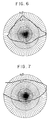
- Fig. 6 is a graph indicating viewing characteristics with regard to contrast of STN-LCD obtained in Example 1.
- Fig. 7 is a graph indicating viewing characteristics with regard to luminance of white image portion of STN-LCD obtained in Example 1.
- Fig. 8 is a graph indicating viewing characteristics with regard to contrast of STN-LCD obtained in Comparison Example 1.
- Fig. 9 is a graph indicating viewing characteristics with regard to luminance of white image portion of STN-LCD obtained in Comparison Example 1.
- Fig. 10 is a graph indicating viewing characteristics with regard to contrast of STN-LCD obtained in Comparison Example 2.
- Fig. 11 is a graph indicating viewing characteristics with regard to luminance of white image portion of STN-LCD obtained in Comparison Example 2.
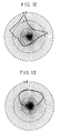
- Fig. 12 is a graph indicating viewing characteristics with regard to contrast of STN-LCD obtained in Comparison Example 3.
- Fig. 13 is a graph indicating viewing characteristics with regard to luminance of white image portion of STN-LCD obtained in Comparison Example 3.
- optical compensatory sheet of the invention is explained below.
- the index ellipsoid of the conventionally employed optical compensatory sheet is shown in Fig. 1.
- the reference number 11 is an index ellipsoid of the optical compensatory sheet and the reference number 12 is a surface of the optical compensatory sheet.
- the reference numbers "nx1" and “ny1” are main refractictive indices on the plane of the sheet, and the reference number “nz1” is a main refractive index in a thickness direction of the sheet (i.e., in the direction perpendicular to the plane of the sheet).
- "nx1" and “ny1" satisfy nx1 > ny1.
- a uniaxial stretched polymer film generally has the index ellipsoid indicated in Fig. 1.
- the index ellipsoid of the optical compensatory sheet of the invention is shown in Fig. 2.
- the reference number 21 is an index ellipsoid of the optical compensatory sheet and the reference number 22 is a surface of the optical compensatory sheet.
- the reference numbers "nx", “ny” and “nz” are main refractictive indices.
- the direction of "nx” is on the plane of the sheet, and the directions of nx and nz are inclined at angle ⁇ by being rotated around the direction of "nx".
- the direction of "ny” is inclined at angle ⁇ from the plane of the sheet (i.e., at angle ⁇ from "y2" which is on the plane of the sheet and is refractive index in the direction perpendicular to "nx") and the direction of nz is inclined at angle ⁇ from the normal of the sheet (i.e., at angle ⁇ from "z2" which is refractive index in the direction perpendicular to the sheet).
- Angle ⁇ preferably is 5 to 40 degrees, more preferably 5 to 30 degrees and especially 12 to 30 degrees.
- "nx”, “ny” and “nz” further satisfy the condition of nx > nz > ny. Further, “nx”, “ny” and “nz” satisfy the condition of: 0.2 ⁇ (nx - nz)/(nx - ny) ⁇ 0.8 wherein nx, ny and nz have the same meanings as defined above.
- the retardation (Re) viewed from the front direction preferably is 50 to 1,000 nm (especially 200 to 600) when it is measured by the use of a light having wavelength of 632.8 nm.
- Transparent substrate 34a and transparent electrode 35a, and transparent substrate 34b and transparent electrodes 35b are superposed, respectively, and the electrodes 35a, 35b are arranged facing each other, between which super twisted nematic liquid crystal 36 is sealed.
- a liquid crystal cell 33 is constructed.
- the optical compensatory sheets 32a, 32b are provided on the substrates 34a, 34b of the liquid crystal cell, respectively, and polarizing plates 31a, 31b are arranged on both sides (optical compensatory sheets 32a, 32b) of the liquid crystal cell, to constitute the liquid crystal display.
- the optical compensatory sheet may be arranged only on one side (i.e., use of one of 32a and 32b). Further, the two optical compensatory sheets may be arranged only on one side in the form of their composite.
- liquid crystal e.g., twisted nematic liquid crystal
- a liquid crystal e.g., twisted nematic liquid crystal
- the super twisted nematic liquid crystal may be employed.
- Fig. 4 The arrangement of the directions of the main refractive indices and various directions in the liquid crystal display of Fig. 3 is shown in Fig. 4.
- Fig. 4 is a perspective view obtained when the liquid crystal display of Fig. 3 is viewed from upper direction.
- the above arrangement is preferably formed by placing the surfaces of the sheets of the sides to which the directions of ny and nz are inclined facing to the surfaces of the liquid crystal cell, and adjusting the angle between two directions of nx of the two sheets to be divided (preferably equally divided) by a bisector of twist angle of the liquid crystal 45.
- optical compensatory sheet of the invention can be prepared in the following manner:
- the optical compensatory sheet may be in the form of film, plate, composite or support provided a coated film.
- the optical compensatory sheet preferably has a transmittance of not less than 80 % and specially not less than 90 %.
- Examples of material employed for the optical compensatory sheet include polymer, optical isomerization substance (low molecular weight compound and polymer) and liquid crystal (low molecular weight compound and polymer).
- any material can be employed so long as they are transparent.
- polymers examples include polycarbonate, polyallylate, polysulfone, polyether sulfone, polyethylene terephthalate, polyphenylene sulfide, polyphenylene oxide, polyallylsulfone, polyvinyl alcohol, polyamide, polyimide, polyolefin (e.g., ZEONEX 280 of Nippon Geon Co., Ltd.), polyvinyl chloride, cellulose derivatives (e.g., triacetyl cellulose), polyacrylonitrile, polystyrene and polymethylmethacrylate.
- the above polymer may be a homopolymer, a copolymer, a derivative thereof or a blended composition comprising two or more kinds of the polymers.
- the optical compensatory sheet can be, for example, prepared using the above polymer in the following manner.
- the polymer film is rolled by passing between two pressure rollers having peripheral speed different from each other (whereby nz is inclined), the resultant continuous film is then uniaxially stretched in the width direction (whereby width direction (usually ny) is transformed to the direction having maximum reflective index (i.e., nx) and further the following process for compressing a film is performed to obtain a sheet satisfying the condition of nx > nz > ny.
- the peripheral speed ratio and the stretching ratio are appropriately changed depending upon nature of used polymer.
- the process for compressing a film is, for example, performed according to the process shown in Fig. 5.
- Cold air e.g., 0°C
- warm air is applied to the lower side, and then the film 51 provided with the surfaces having different temperatures each other is in contact with a heated roller 52 with applying cold air to the upper side, to bend the film along the roller.
- the resultant film is reversed and subjected to the same process as above except for using a heated roller 53.
- the two processes (1 cycle) are generally performed as many as 2 to 20 times.
- the polymer film is rolled by passing between two pressure rollers having peripheral speed different from each other (whereby nz is inclined), and the resultant continuous film is then diaxially stretched at an appropriate stretching ratio (whereby width direction (usually ny) is transformed to nx and nx > nz > ny is obtained).
- an appropriate stretching ratio whereby width direction (usually ny) is transformed to nx and nx > nz > ny is obtained.
- the peripheral speed ratio and the stretching ratio are appropriately changed depending upon nature of used polymer.
- the optical compensatory sheet can be also prepared using optical isomerizable substance.
- the optical isomerization substance means one that can be converted into streoisomer or structural isomer by means of a light.
- the optical isomerizable substance preferably is one that can be reversely isomerized (i.e., returned to the original substance) by means of a light having wavelength different from that used in the above isomerization or by application of heat.
- optical isomerizable substance employed in the invention examples include azobenzene compounds, benzaldoxime compounds, azomethine compounds, stilbene compounds, spiropyran compounds, spiroxazine compounds, fulgide compounds, diarylester compounds, cinnamic acid derivatives, retinal compounds and hemithioindigo compounds.
- the optical isomerizable substance further includes polymers having groups derived from the above compounds or derivatives. Such polymers may have an optical isomerization group on the main chain or the side chain.
- the optical compensatory sheet can be, for example, prepared using the above optical isomerizable substance in the following manner.
- a layer of the optical isomerizable substance (e.g., polymer) satisfying the condition of nx > nz > ny is obliquely irradiated with a light (whereby ny and nz are inclined) to prepare the sheet.
- the sheet can be obtained by obliquely irradiating a layer of the optical isomerizable substance and polymer satisfying the condition of nx > nz > ny with a light or by forming a layer of the optical isomerizable substance on a polymer film satisfying the condition of nx > nz > ny and obliquely irradiating the layer with a light.
- the film was subjected to heat-relaxation at 190°C. Re of the film became almost 0.
- the film was rolled by passing between two heated pressure rollers having peripheral speed different from each other to prepare the film having nz inclined from the normal.
- the resultant film was uniaxially stretched in the width direction at 180°C.
- nx, ny and nz of the obtained film were determined by an ellipsometer (AEP-100, available from Shimadzu Seisakusho, Ltd.). As a result, nx was 1.585, ny was 1.579 and nz was 1.582, and thus the resultant film satisfied the condition of nx > nz > ny. Further, it was apparent that the direction of nx was on the plane of the sheet, the direction of ny was inclined from the plane of the sheet, the direction of nz was inclined from the normal of the sheet, and the inclined angles both were 15 degrees. Moreover, Re measured with a light of 632.8 nm was 385 nm.
- angle between the direction of nx of the lower optical compensatory sheet 42a and the bisector of twist angle of the liquid crystal 45 was made to 10 degrees and angle between the direction of nx of the upper optical compensatory sheet 42b and the bisector of twist angle of the liquid crystal 45 was made to -10 degrees.
- Fig. 6 indicates viewing characteristics with regard to contrast
- Fig. 7 indicates viewing characteristics with regard to luminance of white image portion.
- the center indicates viewing characteristics viewed from the front side of the display
- the upper direction indicates those viewed from direction inclined to the upper side from the center
- the lower direction indicates those viewed from direction inclined to the lower side
- the left direction indicates those viewed from direction inclined to the left side
- the right direction indicates those viewed from direction inclined to the right side.
- the concentric circles indicate, in order from the center, inclined angles of 20 degrees, 40 degrees and 60 degrees.
- the bold curve in Fig. 6 indicates an equal contrast line of STN-LCD obtained in Example 1.
- the bold curve in Fig. 7 indicates an equal luminance line of STN-LCD obtained in Example 1 (luminance: relative value).
- Example 2 The same polymer solution as Example 1 was casted on a steel drum to form a continuous film. Then, the continuous film was continuously peeled off and dried to prepare a continuous film of thickness of 60 ⁇ m and Re of 85 nm. The resultant continuous film was uniaxially stretched in the length direction at 180°C.
- nx, ny and nz of the obtained film were determined in the same manner as Example 1.
- nx was 1.587
- ny and nz were 1.580
- the direction of nz was not inclined from the normal of the sheet.
- Re measure with a light of 632.8 nm was 385 nm.
- STN-LCD was prepared using the obtained film in the same manner as Example 1.
- Fig. 8 and Fig. 9 The viewing characteristics of STN-LCD obtained in Comparison Example 1 are shown in Fig. 8 and Fig. 9.
- the bold curve in Fig. 8 indicates an equal contrast line of STN-LCD of Comparison Example 1.
- the bold curve in Fig. 9 indicates an equal luminance line of STN-LCD of Comparison Example 1.
- Example 2 The same polymer solution as Example 1 was casted on a steel drum to form a continuous film. Then, the continuous film was continuously peeled off and dried to prepare a continuous film of thickness of 200 ⁇ m and Re of 150 nm. The continuous film was subjected to heat-relaxation at 190°C. Re of the film became almost 0.
- the film was subjected to the process for compressing a film shown in Fig. 5 in the same manner as Example 1. Thereafter, the resultant film was uniaxially stretched in the length direction at 180°C.
- nx, ny and nz of the obtained film were determined in the same manner as Example 1.
- nx was 1.585
- ny was 1.579
- nz were 1.582
- the direction of nz was not inclined from the normal of the sheet.
- Re to a light of 632.8 nm was 385 nm.
- STN-LCD was prepared using the obtained film in the same manner as Example 1.
- Fig. 10 The viewing characteristics of STN-LCD obtained in Comparison Example 2 is shown in Fig. 10 and Fig. 11.
- the bold curve in Fig. 10 indicates an equal contrast line of STN-LCD of Comparison Example 2.
- the bold curve in Fig. 11 indicates an equal luminance line of STN-LCD of Comparison Example 2.
- Example 2 The same polymer solution as Example 1 was casted on a steel drum to form a continuous film. Then, the continuous film was continuously peeled off and dried to prepare a continuous film of thickness of 200 ⁇ m and Re of 150 nm. The continuous film was subjected to heat-relaxation at 190°C. Re of the film became almost 0. The continuous film was rolled by passing between two heated pressure rollers having peripheral speed different from each other to prepare the film having nz inclined from the normal.
- the continuous film was subjected to the process for compressing a film shown in Fig. 5 in the same manner as Example 1. Thereafter, the resultant film was uniaxially stretched in the length direction at 180°C.
- nx, ny and nz of the obtained film were determined in the same manner as Example 1.
- nx was 1.585
- ny was 1.579
- nz were 1.582.
- the direction of ny was on the plane of the sheet
- the direction of nx was inclined from the plane of the sheet
- the direction of nz was inclined from the normal of the sheet
- the inclined angles both were 10 degrees.
- Re measured with a light of 632.8 nm was 385 nm.
- STN-LCD was prepared using the obtained film in the same manner as Example 1.
- Fig. 12 The viewing characteristics of STN-LCD obtained in Comparison Example 3 is shown in Fig. 12 and Fig. 13
- the bold curve in Fig. 12 indicates an equal contrast line of STN-LCD of Comparison Example 3.
- the bold curve in Fig. 13 indicates an equal luminance line of STN-LCD of Comparison Example 3.
Abstract
Description
- The present invention relates to an optical compensatory sheet employable for compensating phase difference of a liquid crystal cell, and a liquid crystal display provided with the optical compensatory sheet.
- As a display for electronic office system-devices such as a desk-top personal computer and a word processor for Japanese language, CRT (cathode ray tube) has been employed so far. Recently, a liquid crystal display (hereinafter referred to as LCD) is increasingly employed instead of the CRT because of its thin thickness, light weight and low power consumption. LCD generally has a structure that a liquid crystal cell is disposed between a pair of polarizing sheets. Most of LCD use a twisted nematic liquid crystal or a super twisted nematic liquid crystal.
- A super twisted nematic liquid crystal display (hereinafter referred to as STN-LCD) has been recently utilized for dot-matrix type liquid crystal displays such as those of word processors and personal computers. The liquid crystal display generally has a structure that a liquid crystal cell is disposed between a pair of polarizing sheets. The STN-LCD uses a super twisted nematic liquid crystal showing a twisted angle of 180 to 270 degrees. Such STN-LCD has an advantage of showing a high contrast on high multiplexing drive, compared with the conventional twisted nematic liquid crystal display (twisted angle: 90 degrees) which can be utilized for the dot-matrix type liquid crystal displays.
- However, the STN-LCD has a disadvantage of giving a displayed image inherently colored with the hue from blue or yellow owing to elliptically polarized light transmitted through STN liquid crystal cell. This phenomenon may be hereinafter referred to as coloring. In the STN-LCD, high contrast cannot be obtained in black-and-white display and it is difficult to obtain color image.
- In order to avoid the coloring of the displayed image, there have been proposed a liquid crystal display having one or three layers of optically anisotropic body (that is, NTN mode-display) and a liquid crystal display using a uniaxial stretched polymer film (that is, FTN mode-display).
- The former NTN mode-display shows excellent characteristics in black-and-white display. The liquid crystal cell for optically anisotropic body used in the NTN mode-display is voluminous and a plurality of such cells are required, so that the NTN mode-display is large in volume and weight, and high in production cost compared with the FTN mode-display using a uniaxial stretched polymer film. Hence, the uniaxial stretched polymer film is mainly used as the optical compensatory film.
- Various polymer films (optical compensatory films (birefringence films)), for example a uniaxial stretched polycarbonate film, have been developed for the purpose of the elimination of coloring of the STN-LCD. Thus, the coloring is reduced and the display provided with the film shows almost a black-and-white image.
- The above liquid crystal display provided the uniaxial stretched film has been improved in elimination of coloring, so far as the coloring when the display is viewed from the direction vertical to the screen is concerned. However, when the liquid crystal display is viewed from an oblique direction, unfavorable viewing angle characteristics such as coloring and lowering of contrast of a displayed image and reversing of black-and-white image are observed.
- To improve the above viewing angle characteristics, a method of employing both of a film of positive intrinsic birefringence and a film of negative intrinsic birefringence or employing their composite, and method of employing merely a film of negative intrinsic birefringence have been proposed. These methods, however, scarcely give improvement of the viewing angle characteristics.
- Japanese Patent Provisional Publication No. 2(1990)-285330 discloses that a birefringence film wherein a refractive index in a thickness direction is larger than that in a direction perpendicular to an optic axis of birefringence is employed as the optical compensatory sheet. Such sheet satisfies the condition of nx > nz > ny wherein nx, ny and nz represent main refractictive indices. The use of the birefringence film brings about enhancement of contrast to some extent when the display is viewed from an oblique direction. However, the sheet does not satisfactorily improve the viewing characteristics.
- Further, optical compensatory sheets having oblique optic axis or oblique nz (thickness direction) have been proposed (Japanese Patent Provisional Publications No. 4(1992)-120512, No. 4(1992)-113301, No. 5(1993)-80323 and No. 5(1993)-157913).
- Japanese Patent Provisional Publication No. 4(1992)-120512 discloses an optical sheet whose polymer chain is polarized in the direction at a certain angle to the plane of the sheet. This sheet is considered to satisfy


- Japanese Patent Provisional Publication No. 5(1993)-157913 also discloses an optical sheet that the direction of nz is inclined from the plane of the sheet. Further, the sheet satisfies the condition of nx > nz > ny.
- The above optical compensatory sheets having oblique optic axis also do not improve satisfactorily the viewing angle characteristics such as coloring and contrast of a displayed image, and reversing of black-and-white image, when the liquid crystal display is viewed from an oblique direction.
- When the viewing direction to the liquid crystal display is inclined from the normal to a surface of the display, quality of the displayed image depends upon not only


- In the sheet, tilt angle produced by orientation of liquid crystal in a liquid crystal cell is not considered. Therefore, the viewing angle characteristics such as coloring and contrast of a displayed image and reversing of black-and-white image, when the display is viewed from an oblique direction, are not satisfactorily improved. It is reported that the tilt angle of liquid crystal used for STN-LCD brings about asymmetry of optimum Re in all viewing directions (The 37th Applied Physics Society, 30a-D-10, Spring, 1990).
- As is described above, the optical compensatory sheets having oblique optic axis or oblique nz (thickness direction) are also proposed. Especially, Japanese Patent Provisional Publication No. 5(1993)-157913 discloses an optical sheet whose optic axis is inclined from the plane of the sheet and which satisfies the condition of nx > nz > ny. However, the sheet does not satisfactorily improve the viewing angle characteristics.
- The inventor has studied the reason and found that it is because the oblique nz of the sheet is formed by inclining the plane of nx and nz from the normal of the sheet. In more detail, ny having the minimum refractive index of those of nx, ny and nz, is on the plane of the sheet, and the plane of nx and nz is inclined from the normal of the sheet. According to study of the inventor, it has been apparent that such sheet scarcely compensates the asymmetric property of Re.
- It is an object of the present invention to provide a novel optical compensatory sheet which shows enhanced contrast and reduced coloring in a displayed image and enhanced luminance in black-and-white image when the viewing direction to the liquid crystal display is inclined from the normal to a surface of the display.
- It is another object of the present invention to provide a liquid crystal display provided with a novel optical compensatory sheet which shows enhanced contrast and reduced coloring in a displayed image and enhanced luminance in black-and-white image when the viewing direction to the liquid crystal display is inclined from the normal to a surface of the display.
- It is a further object of the present invention to provide a liquid crystal display using super twisted liquid crystal provided with a novel optical compensatory sheet shows enhanced contrast and reduced coloring in a displayed image and enhanced luminance in black-and-white image when the viewing direction to the liquid crystal display is inclined from the normal to a surface of the display.
- There is provided by the invention an optical compensatory sheet which has main refractictive indices of nx, ny and nz satisfying the condition of nx > nz > ny, wherein the direction of nx is on the plane of the sheet, the direction of ny is inclined from the plane of the sheet and the direction of nz is inclined from the normal to the sheet, the directions of ny and nz crossing each other at right angle.
- Preferred embodiments of the optical compensatory sheet are as follows:
- 1) The optical compensatory sheet wherein the direction of nz is inclined at 5 to 50 degrees to the normal (i.e., normal line) of the sheet.
- 2) The optical compensatory sheet which shows retardation of 50 to 1,000 nm to a light having wavelength of 632.8 nm.
- 3) The optical compensatory sheet as defined in claim 1, nx, ny and nz further satisfy the condition of:

wherein nx, ny and nz have the same meanings as defined above. - 4) The optical compensatory sheet which is made of a polycarbonate film.
- There is further provided by the invention a liquid crystal display comprising a liquid crystal cell which comprises a pair of substrates provided with a transparent electrode and liquid crystal sealed therebetween, a pair of polarizing sheets arranged on both sides of the cell, and an optical compensatory sheet provided between the liquid crystal cell and the polarizing sheet;
wherein the optical compensatory sheet has main refractictive indices of nx, ny and nz satisfying the condition of nx > nz > ny, in which the direction of nx is on the plane of the sheet, the direction of ny is inclined from the plane of the sheet and the direction of nz is inclined from the normal to the sheet, the directions of ny and nz crossing each other at right angle. - Preferred embodiments of the liquid crystal display are as follows:
- 1) The liquid crystal display wherein a pair of the optical compensatory sheets are provided on both sides of the liquid crystal cell, and are arranged in such a manner that the surfaces of the sheets of the sides to which the directions of ny and nz are inclined face to the surfaces of the liquid crystal cell, and angle between two directions of nx of the two sheets is divided (preferably equally divided) by a bisector of twist angle of the liquid crystal.
- 2) The liquid crystal display wherein the liquid crystal is twisted nematic liquid crystal or super twisted nematic liquid crystal (preferably super twisted nematic liquid crystal).
- The optical compensatory sheet of the invention shows greatly enhanced contrast and reduced coloring in a displayed image and enhanced luminance in black-and-white image when the viewing direction is inclined from the normal to a surface of the display. Thus, the liquid crystal display provided with the optical compensatory sheet shows excellent viewing characteristics described above.
- Particularly, in the case of normally black mode of STN-LCD, viewing angle is increased and bright white image can be obtained.
- Further, the optical compensatory sheet of the invention is also advantageously employed for an active matrix liquid crystal display such as TFT or MIN.
- Fig. 1 is a view schematically showing the index ellipsoid of a conventionally employed optical compensatory sheet.
- Fig. 2 is a view schematically showing the index ellipsoid of the optical compensatory sheet of the invention.
- Fig. 3 is a sectional view schematically showing the representative structure of the liquid crystal display of the invention.
- Fig. 4 is a perspective view obtained when the liquid crystal display of Fig. 3 is viewed from upper direction, which shows the arrangement of the directions of the main refractive indices and various directions in the liquid crystal display of Fig. 3.
- Fig. 5 is a view showing a process for compressing a film.
- Fig. 6 is a graph indicating viewing characteristics with regard to contrast of STN-LCD obtained in Example 1.
- Fig. 7 is a graph indicating viewing characteristics with regard to luminance of white image portion of STN-LCD obtained in Example 1.
- Fig. 8 is a graph indicating viewing characteristics with regard to contrast of STN-LCD obtained in Comparison Example 1.
- Fig. 9 is a graph indicating viewing characteristics with regard to luminance of white image portion of STN-LCD obtained in Comparison Example 1.
- Fig. 10 is a graph indicating viewing characteristics with regard to contrast of STN-LCD obtained in Comparison Example 2.
- Fig. 11 is a graph indicating viewing characteristics with regard to luminance of white image portion of STN-LCD obtained in Comparison Example 2.
- Fig. 12 is a graph indicating viewing characteristics with regard to contrast of STN-LCD obtained in Comparison Example 3.
- Fig. 13 is a graph indicating viewing characteristics with regard to luminance of white image portion of STN-LCD obtained in Comparison Example 3.
- The optical compensatory sheet of the invention is explained below.
- The index ellipsoid of the conventionally employed optical compensatory sheet is shown in Fig. 1.
- The
reference number 11 is an index ellipsoid of the optical compensatory sheet and thereference number 12 is a surface of the optical compensatory sheet. The reference numbers "nx¹" and "ny¹" are main refractictive indices on the plane of the sheet, and the reference number "nz¹" is a main refractive index in a thickness direction of the sheet (i.e., in the direction perpendicular to the plane of the sheet). In the index ellipsoid, "nx¹" and "ny¹" satisfy nx¹ > ny¹. A uniaxial stretched polymer film generally has the index ellipsoid indicated in Fig. 1. - The index ellipsoid of the optical compensatory sheet of the invention is shown in Fig. 2.
- The
reference number 21 is an index ellipsoid of the optical compensatory sheet and thereference number 22 is a surface of the optical compensatory sheet. The reference numbers "nx", "ny" and "nz" are main refractictive indices. The direction of "nx" is on the plane of the sheet, and the directions of nx and nz are inclined at angle ϑ by being rotated around the direction of "nx". In more detail, the direction of "ny" is inclined at angle ϑ from the plane of the sheet (i.e., at angle ϑ from "y²" which is on the plane of the sheet and is refractive index in the direction perpendicular to "nx") and the direction of nz is inclined at angle ϑ from the normal of the sheet (i.e., at angle ϑ from "z²" which is refractive index in the direction perpendicular to the sheet). - Angle ϑ preferably is 5 to 40 degrees, more preferably 5 to 30 degrees and especially 12 to 30 degrees. In Fig. 2, "nx", "ny" and "nz" further satisfy the condition of nx > nz > ny. Further, "nx", "ny" and "nz" satisfy the condition of:

wherein nx, ny and nz have the same meanings as defined above. - In the invention, the retardation (Re) viewed from the front direction preferably is 50 to 1,000 nm (especially 200 to 600) when it is measured by the use of a light having wavelength of 632.8 nm. The retardation (Re) is determined by product (Δn·d) of birefringence

- The representative structure of the liquid crystal display provided with the optical compensatory sheet according to the invention is shown in Fig. 3.
-
Transparent substrate 34a andtransparent electrode 35a, andtransparent substrate 34b andtransparent electrodes 35b are superposed, respectively, and theelectrodes liquid crystal 36 is sealed. In this manner, aliquid crystal cell 33 is constructed. The opticalcompensatory sheets substrates polarizing plates compensatory sheets - The optical compensatory sheet may be arranged only on one side (i.e., use of one of 32a and 32b). Further, the two optical compensatory sheets may be arranged only on one side in the form of their composite. As liquid crystal, a liquid crystal (e.g., twisted nematic liquid crystal) other than the super twisted nematic liquid crystal may be employed.
- The arrangement of the directions of the main refractive indices and various directions in the liquid crystal display of Fig. 3 is shown in Fig. 4.
- Fig. 4 is a perspective view obtained when the liquid crystal display of Fig. 3 is viewed from upper direction. The direction of nx of the lower optical compensatory sheet (32a in Fig. 3) 42a, the direction of nx of the upper optical compensatory sheet (32b in Fig. 3) 42b, the rubbing direction on the lower transparent substrates (34a in Fig. 3) 46, the rubbing direction on the upper transparent substrates (34a in Fig. 3) 47, the bisector of twist angle of the
liquid crystal 45, the twist angle of theliquid crystal 48, the inclined direction of nz (direction of nz rotating around nx) of the lower opticalcompensatory sheet 43 and the inclined direction of nz of the upper opticalcompensatory sheet 44, are indicated. - The above arrangement is preferably formed by placing the surfaces of the sheets of the sides to which the directions of ny and nz are inclined facing to the surfaces of the liquid crystal cell, and adjusting the angle between two directions of nx of the two sheets to be divided (preferably equally divided) by a bisector of twist angle of the
liquid crystal 45. - The optical compensatory sheet of the invention can be prepared in the following manner:
- The optical compensatory sheet may be in the form of film, plate, composite or support provided a coated film. The optical compensatory sheet preferably has a transmittance of not less than 80 % and specially not less than 90 %. Examples of material employed for the optical compensatory sheet include polymer, optical isomerization substance (low molecular weight compound and polymer) and liquid crystal (low molecular weight compound and polymer).
- As polymer material employed in the invention, any material can be employed so long as they are transparent.
- Examples of the above polymers include polycarbonate, polyallylate, polysulfone, polyether sulfone, polyethylene terephthalate, polyphenylene sulfide, polyphenylene oxide, polyallylsulfone, polyvinyl alcohol, polyamide, polyimide, polyolefin (e.g., ZEONEX 280 of Nippon Geon Co., Ltd.), polyvinyl chloride, cellulose derivatives (e.g., triacetyl cellulose), polyacrylonitrile, polystyrene and polymethylmethacrylate. The above polymer may be a homopolymer, a copolymer, a derivative thereof or a blended composition comprising two or more kinds of the polymers.
- The optical compensatory sheet can be, for example, prepared using the above polymer in the following manner.
- The polymer film is rolled by passing between two pressure rollers having peripheral speed different from each other (whereby nz is inclined), the resultant continuous film is then uniaxially stretched in the width direction (whereby width direction (usually ny) is transformed to the direction having maximum reflective index (i.e., nx) and further the following process for compressing a film is performed to obtain a sheet satisfying the condition of nx > nz > ny. To obtain such optical compensatory sheet, the peripheral speed ratio and the stretching ratio are appropriately changed depending upon nature of used polymer.
- The process for compressing a film is, for example, performed according to the process shown in Fig. 5. Cold air (e.g., 0°C) is applied to the upper side of the stretched
film 51 and warm air is applied to the lower side, and then thefilm 51 provided with the surfaces having different temperatures each other is in contact with aheated roller 52 with applying cold air to the upper side, to bend the film along the roller. Then, the resultant film is reversed and subjected to the same process as above except for using aheated roller 53. The two processes (1 cycle) are generally performed as many as 2 to 20 times. - Alternatively, the polymer film is rolled by passing between two pressure rollers having peripheral speed different from each other (whereby nz is inclined), and the resultant continuous film is then diaxially stretched at an appropriate stretching ratio (whereby width direction (usually ny) is transformed to nx and nx > nz > ny is obtained). To obtain such optical compensatory sheet, the peripheral speed ratio and the stretching ratio are appropriately changed depending upon nature of used polymer.
- The optical compensatory sheet can be also prepared using optical isomerizable substance. The optical isomerization substance means one that can be converted into streoisomer or structural isomer by means of a light. The optical isomerizable substance preferably is one that can be reversely isomerized (i.e., returned to the original substance) by means of a light having wavelength different from that used in the above isomerization or by application of heat. Examples of the optical isomerizable substance employed in the invention include azobenzene compounds, benzaldoxime compounds, azomethine compounds, stilbene compounds, spiropyran compounds, spiroxazine compounds, fulgide compounds, diarylester compounds, cinnamic acid derivatives, retinal compounds and hemithioindigo compounds. The optical isomerizable substance further includes polymers having groups derived from the above compounds or derivatives. Such polymers may have an optical isomerization group on the main chain or the side chain.
- The optical compensatory sheet can be, for example, prepared using the above optical isomerizable substance in the following manner.
- A layer of the optical isomerizable substance (e.g., polymer) satisfying the condition of nx > nz > ny is obliquely irradiated with a light (whereby ny and nz are inclined) to prepare the sheet. Alternatively, the sheet can be obtained by obliquely irradiating a layer of the optical isomerizable substance and polymer satisfying the condition of nx > nz > ny with a light or by forming a layer of the optical isomerizable substance on a polymer film satisfying the condition of nx > nz > ny and obliquely irradiating the layer with a light.
- Examples of the present invention and comparison examples are given below, but these examples by no means restrict the invention.
- Polycarbonate (weight-average molecular weight: 120,000) prepared by polycondensation of phosgene and bisphenol A was dissolved in dichloromethane to prepare a solution of 18 weight %. The polymer solution was casted on a steel drum to form a continuous film. Then, the continuous film was continuously peeled off and dried to prepare a continuous film of thickness of 200 µm. As to this film, Re to a light of 632.8 nm (wavelength) was measured by an ellipsometer (AEP-100, available from Shimadzu Seisakusho, Ltd.). The resultant value of Re was 150 nm. The Re is assumed to be produced by the tension when the film was peeled off.
- The film was subjected to heat-relaxation at 190°C. Re of the film became almost 0. The film was rolled by passing between two heated pressure rollers having peripheral speed different from each other to prepare the film having nz inclined from the normal. The resultant film was uniaxially stretched in the width direction at 180°C.
- Further, according to the process for compressing a film shown in Fig. 5, cold air (0°C) was applied to the upper side of the stretched
film 51 and warm air was applied to the lower side, and thefilm 51 having the surfaces of different temperatures was in contact with a heated roller 52 (diameter: 12.5 m; temperature: 158°C) with applying cold air to the upper side, to bend the film along the roller. The processed film had the upper side of temperature of 128°C and the lower side of temperature of 158°C. Then, the film was reversed and was subjected to performance of the same process as above except for using aheated roller 53. The two processes (1 cycle) were performed 10 times. - nx, ny and nz of the obtained film were determined by an ellipsometer (AEP-100, available from Shimadzu Seisakusho, Ltd.). As a result, nx was 1.585, ny was 1.579 and nz was 1.582, and thus the resultant film satisfied the condition of nx > nz > ny. Further, it was apparent that the direction of nx was on the plane of the sheet, the direction of ny was inclined from the plane of the sheet, the direction of nz was inclined from the normal of the sheet, and the inclined angles both were 15 degrees. Moreover, Re measured with a light of 632.8 nm was 385 nm.
- To STN-liquid crystal cell in the personal word-processor "WD-A551" (manufactured by Sharp Corporation), the obtained sheets were fixed as shown in Fig. 3 to obtain STN-LCD. The arrangement of the directions of the main refractive indices of the sheet and various directions of the liquid crystal display was formed as shown in Fig. 4. In more detail, under the conditions that a light source was placed under the
polarizing plate 31a and a clockwise direction to the course of the light was made to positive, angle between the direction of nx of the lower opticalcompensatory sheet 42a and the bisector of twist angle of theliquid crystal 45 was made to 10 degrees and angle between the direction of nx of the upper opticalcompensatory sheet 42b and the bisector of twist angle of theliquid crystal 45 was made to -10 degrees. - The viewing characteristics of STN-LCD obtained in Example 1 are shown in Fig. 6 and Fig. 7. Fig. 6 indicates viewing characteristics with regard to contrast, and Fig. 7 indicates viewing characteristics with regard to luminance of white image portion. In figures, the center indicates viewing characteristics viewed from the front side of the display, and the upper direction indicates those viewed from direction inclined to the upper side from the center, the lower direction indicates those viewed from direction inclined to the lower side, the left direction indicates those viewed from direction inclined to the left side and the right direction indicates those viewed from direction inclined to the right side. The concentric circles indicate, in order from the center, inclined angles of 20 degrees, 40 degrees and 60 degrees.
- The bold curve in Fig. 6 indicates an equal contrast line of STN-LCD obtained in Example 1. The bold curve in Fig. 7 indicates an equal luminance line of STN-LCD obtained in Example 1 (luminance: relative value). These results showed that TN-LCD of Example 1 had high contrast and luminance in the wide range of viewing angles.
- The same polymer solution as Example 1 was casted on a steel drum to form a continuous film. Then, the continuous film was continuously peeled off and dried to prepare a continuous film of thickness of 60 µm and Re of 85 nm. The resultant continuous film was uniaxially stretched in the length direction at 180°C.
- nx, ny and nz of the obtained film were determined in the same manner as Example 1. As a result, nx was 1.587, ny and nz were 1.580, and the direction of nz was not inclined from the normal of the sheet. Moreover, Re measure with a light of 632.8 nm was 385 nm.
- STN-LCD was prepared using the obtained film in the same manner as Example 1.
- The viewing characteristics of STN-LCD obtained in Comparison Example 1 are shown in Fig. 8 and Fig. 9. The bold curve in Fig. 8 indicates an equal contrast line of STN-LCD of Comparison Example 1. The bold curve in Fig. 9 indicates an equal luminance line of STN-LCD of Comparison Example 1. These results showed that TN-LCD of Comparison Example 1 had high contrast and luminance in the narrow range of viewing angles.
- The same polymer solution as Example 1 was casted on a steel drum to form a continuous film. Then, the continuous film was continuously peeled off and dried to prepare a continuous film of thickness of 200 µm and Re of 150 nm. The continuous film was subjected to heat-relaxation at 190°C. Re of the film became almost 0.
- The film was subjected to the process for compressing a film shown in Fig. 5 in the same manner as Example 1. Thereafter, the resultant film was uniaxially stretched in the length direction at 180°C.
- nx, ny and nz of the obtained film were determined in the same manner as Example 1. As a result, nx was 1.585, ny was 1.579 and nz were 1.582, and the direction of nz was not inclined from the normal of the sheet. Moreover, Re to a light of 632.8 nm was 385 nm.
- STN-LCD was prepared using the obtained film in the same manner as Example 1.
- The viewing characteristics of STN-LCD obtained in Comparison Example 2 is shown in Fig. 10 and Fig. 11. The bold curve in Fig. 10 indicates an equal contrast line of STN-LCD of Comparison Example 2. The bold curve in Fig. 11 indicates an equal luminance line of STN-LCD of Comparison Example 2. These results showed that TN-LCD of Comparison Example 2 did not have high contrast and luminance in the wide range of viewing angles.
- The same polymer solution as Example 1 was casted on a steel drum to form a continuous film. Then, the continuous film was continuously peeled off and dried to prepare a continuous film of thickness of 200 µm and Re of 150 nm. The continuous film was subjected to heat-relaxation at 190°C. Re of the film became almost 0. The continuous film was rolled by passing between two heated pressure rollers having peripheral speed different from each other to prepare the film having nz inclined from the normal.
- The continuous film was subjected to the process for compressing a film shown in Fig. 5 in the same manner as Example 1. Thereafter, the resultant film was uniaxially stretched in the length direction at 180°C.
- nx, ny and nz of the obtained film were determined in the same manner as Example 1. As a result, nx was 1.585, ny was 1.579 and nz were 1.582. Further, it was apparent that the direction of ny was on the plane of the sheet, the direction of nx was inclined from the plane of the sheet, the direction of nz was inclined from the normal of the sheet, and the inclined angles both were 10 degrees. Moreover, Re measured with a light of 632.8 nm was 385 nm.
- STN-LCD was prepared using the obtained film in the same manner as Example 1.
- The viewing characteristics of STN-LCD obtained in Comparison Example 3 is shown in Fig. 12 and Fig. 13 The bold curve in Fig. 12 indicates an equal contrast line of STN-LCD of Comparison Example 3. The bold curve in Fig. 13 indicates an equal luminance line of STN-LCD of Comparison Example 3. These results showed that TN-LCD of Comparison Example 3 did not have high contrast and luminance in the wide range of viewing angles.
Claims (7)
- An optical compensatory sheet which has main refractictive indices of nx, ny and nz satisfying the condition of nx > nz > ny, wherein the direction of nx is on the plane of the sheet, the direction of ny is inclined from the plane of the sheet and the direction of nz is inclined from the normal to the sheet, the directions of ny and nz crossing each other at right angle.
- The optical compensatory sheet as defined in claim 1, wherein the direction of nz is inclined at 5 to 50 degrees from the normal to the sheet.
- The optical compensatory sheet as defined in claims 1 or 2, which shows retardation of 50 to 1,000 nm to a light having wavelength of 632.8 nm.
- The optical compensatory sheet as defined in claims 1 to 3, nx, ny and nz further satisfy the condition of:

wherein nx, ny and nz have the same meanings as defined in claim 1. - A liquid crystal display comprising a liquid crystal cell which comprises a pair of substrates provided with a transparent electrode and liquid crystal sealed therebetween, a pair of polarizing sheets arranged on both sides of the cell, and an optical compensatory sheet provided between the liquid crystal cell and the polarizing sheet; wherein the optical compensatory sheet has main refractictive indices of nx, ny and nz satisfying the condition of nx > nz > ny, in which the direction of nx is on the plane of the sheet, the direction of ny is inclined from the plane of the sheet and the direction of nz is inclined from the normal to the sheet, the directions of ny and nz crossing each other at right angle.
- The liquid crystal display as defined in claim 5, wherein a pair of the optical compensatory sheets are provided on both sides of the liquid crystal cell, and are arranged in such a manner that the surfaces of the sheets of the sides to which the directions of ny and nz are inclined face to the surfaces of the liquid crystal cell, and angle formed where two directions of nx of the two sheets cross each other is equally divided by a bisector of twist angle of the liquid crystal.
- The liquid crystal display as defined in claims 5 and 6 wherein the liquid crystal is super twisted nematic liquid crystal.
Applications Claiming Priority (3)
| Application Number | Priority Date | Filing Date | Title |
|---|---|---|---|
| JP264996/93 | 1993-10-22 | ||
| JP26499693 | 1993-10-22 | ||
| JP26499693A JP3325973B2 (en) | 1993-10-22 | 1993-10-22 | Optical anisotropic element and liquid crystal display element using the same |
Publications (2)
| Publication Number | Publication Date |
|---|---|
| EP0650079A1 true EP0650079A1 (en) | 1995-04-26 |
| EP0650079B1 EP0650079B1 (en) | 2001-03-07 |
Family
ID=17411124
Family Applications (1)
| Application Number | Title | Priority Date | Filing Date |
|---|---|---|---|
| EP94116645A Expired - Lifetime EP0650079B1 (en) | 1993-10-22 | 1994-10-21 | Optical compensatory sheet and liquid crystal display having the same |
Country Status (4)
| Country | Link |
|---|---|
| US (1) | US5559618A (en) |
| EP (1) | EP0650079B1 (en) |
| JP (1) | JP3325973B2 (en) |
| DE (1) | DE69426800T2 (en) |
Cited By (2)
| Publication number | Priority date | Publication date | Assignee | Title |
|---|---|---|---|---|
| EP1329747A1 (en) * | 2000-10-20 | 2003-07-23 | Fuji Photo Film Co., Ltd. | Cellulose acetate film with regulated retardation and thickness |
| US8071180B2 (en) | 1999-06-21 | 2011-12-06 | Cambridge University Technical Services Limited | Aligned polymer organic TFT |
Families Citing this family (26)
| Publication number | Priority date | Publication date | Assignee | Title |
|---|---|---|---|---|
| US5986734A (en) * | 1994-04-04 | 1999-11-16 | Rockwell International Corporation | Organic polymer O-plate compensator for improved gray scale performance in twisted nematic liquid crystal displays |
| WO1996023244A1 (en) * | 1995-01-23 | 1996-08-01 | Asahi Glass Company Ltd. | Color liquid crystal display apparatus |
| US5718838A (en) * | 1995-08-10 | 1998-02-17 | Fuji Photo Film Co., Ltd. | Optical compensatory sheet, process for the preparation of the same and liquid crystal display |
| US5853801A (en) * | 1995-09-04 | 1998-12-29 | Fuji Photo Film Co., Ltd. | Process for the preparation of continuous optical compensatory sheet |
| JP2822983B2 (en) | 1996-06-27 | 1998-11-11 | 日本電気株式会社 | Transmissive liquid crystal display |
| TW515925B (en) * | 1996-12-25 | 2003-01-01 | Sharp Kk | Liquid crystal display device |
| US5990997A (en) * | 1997-06-05 | 1999-11-23 | Ois Optical Imaging Systems, Inc. | NW twisted nematic LCD with negative tilted retarders for improved viewing characteristics |
| US6567143B1 (en) | 1997-06-05 | 2003-05-20 | Guardian Industries Corp. | NW twisted nematic LCD with negative and tilted retarders on each side of liquid crystal cell to improve vertical contrast ratios |
| US5953091A (en) * | 1998-04-09 | 1999-09-14 | Ois Optical Imaging Systems, Inc. | Multi-domain LCD and method of making same |
| US6124907A (en) * | 1998-04-24 | 2000-09-26 | Ois Optical Imaging Systems, Inc. | Liquid crystal display with internal polarizer and method of making same |
| JP2001195770A (en) * | 2000-01-14 | 2001-07-19 | Sharp Corp | Optical pickup |
| JP2001201740A (en) * | 2000-01-21 | 2001-07-27 | Citizen Watch Co Ltd | Reflective liquid crystal display device |
| SI21526A (en) * | 2003-05-16 | 2004-12-31 | Institut "Jožef Stefan" | High contrast, wide viewing angle lcd light-switching element |
| KR100978323B1 (en) * | 2003-10-15 | 2010-08-26 | 하야시 텔렘프 가부시끼가이샤 | Retardation film and process for producing the same |
| US20050083463A1 (en) * | 2003-10-17 | 2005-04-21 | Hayashi Telempu Co., Ltd | Retardation film and process for producing the same |
| JP2006106180A (en) * | 2004-10-01 | 2006-04-20 | Nitto Denko Corp | Optical film and image display |
| JP2006113434A (en) * | 2004-10-18 | 2006-04-27 | Konica Minolta Holdings Inc | Video display apparatus |
| JP3851918B2 (en) * | 2004-10-22 | 2006-11-29 | 日東電工株式会社 | Liquid crystal panel and liquid crystal display device |
| JP4530276B2 (en) * | 2005-01-31 | 2010-08-25 | 日東電工株式会社 | Polarizing element, liquid crystal panel, and liquid crystal display device |
| JPWO2006117981A1 (en) * | 2005-04-26 | 2008-12-18 | コニカミノルタオプト株式会社 | Optical film, polarizing plate, and transverse electric field switching mode type liquid crystal display device |
| US20070030417A1 (en) * | 2005-04-28 | 2007-02-08 | Nobuo Kubo | Cellulose ester film, polarizing plate and liquid crystal display |
| WO2006118038A1 (en) * | 2005-04-28 | 2006-11-09 | Konica Minolta Opto, Inc. | Optical film, polarizing plate and traverse field switching mode type liquid crystal display unit |
| JP4789139B2 (en) * | 2005-05-11 | 2011-10-12 | 日東電工株式会社 | Liquid crystal panel and liquid crystal display device using the same |
| US20070013843A1 (en) * | 2005-07-12 | 2007-01-18 | Yuuichi Nishikouji | Liquid crystal panel and liquid crystal display using the same |
| US20070013844A1 (en) * | 2005-07-12 | 2007-01-18 | Nitto Denko Corporation | Liquid crystal panel and liquid crystal display using the same |
| JP2015138162A (en) * | 2014-01-23 | 2015-07-30 | 住友化学株式会社 | Optical anisotropic film |
Citations (7)
| Publication number | Priority date | Publication date | Assignee | Title |
|---|---|---|---|---|
| US3924930A (en) * | 1974-08-29 | 1975-12-09 | Hughes Aircraft Co | Optical partial wave plate and method of fabricating and using same |
| JPH04113301A (en) * | 1990-09-03 | 1992-04-14 | Asahi Chem Ind Co Ltd | New optical sheet and liquid crystal display device using same sheet |
| JPH04120512A (en) * | 1990-09-12 | 1992-04-21 | Asahi Chem Ind Co Ltd | New optical sheet and liquid crystal display device provided therewith |
| US5194975A (en) * | 1989-03-28 | 1993-03-16 | Asahi Glass Company Ltd. | Liquid crystal display device having biaxial birefringent plates at each side of the liquid crystal layer |
| JPH0580323A (en) * | 1991-09-25 | 1993-04-02 | Nec Corp | Liquid crystal display device |
| JPH05157913A (en) * | 1991-12-10 | 1993-06-25 | Seiko Epson Corp | Phase difference film and liquid crystal display element |
| EP0576304A1 (en) * | 1992-06-26 | 1993-12-29 | Sharp Kabushiki Kaisha | Phase difference plate and liquid crystal display device |
Family Cites Families (11)
| Publication number | Priority date | Publication date | Assignee | Title |
|---|---|---|---|---|
| JP2768977B2 (en) * | 1989-05-23 | 1998-06-25 | 旭硝子株式会社 | Liquid crystal element and device using the same |
| JPH02285303A (en) * | 1989-04-26 | 1990-11-22 | Nitto Denko Corp | Double refractive film and production thereof and phase difference plate and liquid crystal panel |
| US5175638A (en) * | 1989-09-12 | 1992-12-29 | Ricoh Company, Ltd. | ECB type liquid crystal display device having birefringent layer with equal refractive indexes in the thickness and plane directions |
| US5184237A (en) * | 1990-03-27 | 1993-02-02 | Ricoh Company, Ltd. | Super-twisted nematic type liquid crystal display device |
| JP2818983B2 (en) * | 1990-10-24 | 1998-10-30 | 日東電工株式会社 | Method for producing birefringent film |
| US5245456A (en) * | 1990-10-24 | 1993-09-14 | Nitto Denko Corporation | Birefringent film with nx >nz >ny, process for producing the same, retardation film, elliptically polarizing plate, and liquid crystal display |
| JP3313408B2 (en) * | 1991-06-17 | 2002-08-12 | セイコーエプソン株式会社 | Retardation film, retardation plate, and liquid crystal display device using the same |
| US5227903A (en) * | 1991-09-20 | 1993-07-13 | Casio Computer Co., Ltd. | Liquid crystal display device with at least one biaxial retardation film having nx >nz >ny |
| FR2693020B1 (en) * | 1992-06-26 | 1999-01-22 | Thomson Consumer Electronics | NEMATIC LIQUID CRYSTAL DISPLAY DEVICE. |
| JP2880614B2 (en) * | 1992-12-07 | 1999-04-12 | 富士写真フイルム株式会社 | Optical compensation sheet and liquid crystal display device using the same |
| JP2624116B2 (en) * | 1993-04-22 | 1997-06-25 | 松下電器産業株式会社 | Liquid crystal display device and projection display device using the same |
-
1993
- 1993-10-22 JP JP26499693A patent/JP3325973B2/en not_active Expired - Lifetime
-
1994
- 1994-10-20 US US08/327,794 patent/US5559618A/en not_active Expired - Lifetime
- 1994-10-21 DE DE69426800T patent/DE69426800T2/en not_active Expired - Lifetime
- 1994-10-21 EP EP94116645A patent/EP0650079B1/en not_active Expired - Lifetime
Patent Citations (7)
| Publication number | Priority date | Publication date | Assignee | Title |
|---|---|---|---|---|
| US3924930A (en) * | 1974-08-29 | 1975-12-09 | Hughes Aircraft Co | Optical partial wave plate and method of fabricating and using same |
| US5194975A (en) * | 1989-03-28 | 1993-03-16 | Asahi Glass Company Ltd. | Liquid crystal display device having biaxial birefringent plates at each side of the liquid crystal layer |
| JPH04113301A (en) * | 1990-09-03 | 1992-04-14 | Asahi Chem Ind Co Ltd | New optical sheet and liquid crystal display device using same sheet |
| JPH04120512A (en) * | 1990-09-12 | 1992-04-21 | Asahi Chem Ind Co Ltd | New optical sheet and liquid crystal display device provided therewith |
| JPH0580323A (en) * | 1991-09-25 | 1993-04-02 | Nec Corp | Liquid crystal display device |
| JPH05157913A (en) * | 1991-12-10 | 1993-06-25 | Seiko Epson Corp | Phase difference film and liquid crystal display element |
| EP0576304A1 (en) * | 1992-06-26 | 1993-12-29 | Sharp Kabushiki Kaisha | Phase difference plate and liquid crystal display device |
Non-Patent Citations (4)
| Title |
|---|
| PATENT ABSTRACTS OF JAPAN vol. 16, no. 365 (P - 1397) 6 August 1992 (1992-08-06) * |
| PATENT ABSTRACTS OF JAPAN vol. 16, no. 377 (P - 1401) 12 August 1992 (1992-08-12) * |
| PATENT ABSTRACTS OF JAPAN vol. 17, no. 416 (P - 1584) 3 August 1993 (1993-08-03) * |
| PATENT ABSTRACTS OF JAPAN vol. 17, no. 553 (P - 1625) 5 October 1993 (1993-10-05) * |
Cited By (4)
| Publication number | Priority date | Publication date | Assignee | Title |
|---|---|---|---|---|
| US8071180B2 (en) | 1999-06-21 | 2011-12-06 | Cambridge University Technical Services Limited | Aligned polymer organic TFT |
| US8541257B2 (en) | 1999-06-21 | 2013-09-24 | Cambridge University Technical Services Limited | Aligned polymers for an organic TFT |
| EP1329747A1 (en) * | 2000-10-20 | 2003-07-23 | Fuji Photo Film Co., Ltd. | Cellulose acetate film with regulated retardation and thickness |
| EP1329747A4 (en) * | 2000-10-20 | 2006-06-07 | Fuji Photo Film Co Ltd | Cellulose acetate film with regulated retardation and thickness |
Also Published As
| Publication number | Publication date |
|---|---|
| US5559618A (en) | 1996-09-24 |
| DE69426800T2 (en) | 2001-07-12 |
| DE69426800D1 (en) | 2001-04-12 |
| EP0650079B1 (en) | 2001-03-07 |
| JP3325973B2 (en) | 2002-09-17 |
| JPH07120619A (en) | 1995-05-12 |
Similar Documents
| Publication | Publication Date | Title |
|---|---|---|
| EP0650079B1 (en) | Optical compensatory sheet and liquid crystal display having the same | |
| EP0424951B1 (en) | Liquid crystal display | |
| US5568290A (en) | Elliptically polarizing plate comprising discotic liquid crystal and in which 30≦[(NX+NY)/2--NZ]×D≦150 | |
| US5793455A (en) | Elliptically polarizing plate and liquid crystal display in which a compensation sheet direction of non-zero minimum retardation is inclined at 5 to 50 degrees | |
| US5119220A (en) | Liquid crystal display device with a phase plate for shadow compensation | |
| EP1207408B1 (en) | Process for preparing an optical compensatory sheet | |
| US5142393A (en) | Electro-optical liquid crystal device with compensator having negative optical anisotropy | |
| US6411355B1 (en) | Liquid crystal display device with compensation for viewing angle dependency and optical anisotropic element used therein | |
| US5213852A (en) | Phase difference film and liquid crystal display having the same | |
| EP0864906A1 (en) | Liquid crystal display and optical compensatory sheet | |
| JP4125876B2 (en) | Transflective liquid crystal display device | |
| US6351299B2 (en) | Liquid crystal display device | |
| JP3712833B2 (en) | Reflective liquid crystal display | |
| JP3568641B2 (en) | Optical anisotropic element and liquid crystal display element using the same | |
| JP3206177B2 (en) | Phase difference plate and liquid crystal display device using the same | |
| JPH08101381A (en) | Liquid crystal display element | |
| JP2706902B2 (en) | Color liquid crystal display | |
| JPH07128659A (en) | Liquid crystal display element formed by using optical anisotropic element | |
| JP2005164957A (en) | Circularly polarizing plate and liquid crystal display element | |
| JPH0850270A (en) | Liquid crystal display element formed by using optically anisotropic element | |
| JP3000374B2 (en) | Liquid crystal display device | |
| JPH0895032A (en) | Elliptically polarizing plate and color liquid crystal display device | |
| JPH08101380A (en) | Reflection type liquid crystal display device | |
| JPH07294736A (en) | Optically anisotropic element and liquid crystal display element formed by using the same | |
| JP2749846B2 (en) | Liquid crystal display device |
Legal Events
| Date | Code | Title | Description |
|---|---|---|---|
| PUAI | Public reference made under article 153(3) epc to a published international application that has entered the european phase |
Free format text: ORIGINAL CODE: 0009012 |
|
| AK | Designated contracting states |
Kind code of ref document: A1 Designated state(s): DE FR GB |
|
| 17P | Request for examination filed |
Effective date: 19950607 |
|
| 17Q | First examination report despatched |
Effective date: 19970206 |
|
| GRAG | Despatch of communication of intention to grant |
Free format text: ORIGINAL CODE: EPIDOS AGRA |
|
| GRAG | Despatch of communication of intention to grant |
Free format text: ORIGINAL CODE: EPIDOS AGRA |
|
| GRAH | Despatch of communication of intention to grant a patent |
Free format text: ORIGINAL CODE: EPIDOS IGRA |
|
| GRAH | Despatch of communication of intention to grant a patent |
Free format text: ORIGINAL CODE: EPIDOS IGRA |
|
| GRAA | (expected) grant |
Free format text: ORIGINAL CODE: 0009210 |
|
| AK | Designated contracting states |
Kind code of ref document: B1 Designated state(s): DE FR GB |
|
| PG25 | Lapsed in a contracting state [announced via postgrant information from national office to epo] |
Ref country code: FR Free format text: LAPSE BECAUSE OF FAILURE TO SUBMIT A TRANSLATION OF THE DESCRIPTION OR TO PAY THE FEE WITHIN THE PRESCRIBED TIME-LIMIT Effective date: 20010307 |
|
| REF | Corresponds to: |
Ref document number: 69426800 Country of ref document: DE Date of ref document: 20010412 |
|
| EN | Fr: translation not filed | ||
| REG | Reference to a national code |
Ref country code: GB Ref legal event code: IF02 |
|
| PLBE | No opposition filed within time limit |
Free format text: ORIGINAL CODE: 0009261 |
|
| STAA | Information on the status of an ep patent application or granted ep patent |
Free format text: STATUS: NO OPPOSITION FILED WITHIN TIME LIMIT |
|
| 26N | No opposition filed | ||
| REG | Reference to a national code |
Ref country code: GB Ref legal event code: 732E |
|
| PGFP | Annual fee paid to national office [announced via postgrant information from national office to epo] |
Ref country code: DE Payment date: 20090923 Year of fee payment: 16 |
|
| PGFP | Annual fee paid to national office [announced via postgrant information from national office to epo] |
Ref country code: GB Payment date: 20091021 Year of fee payment: 16 |
|
| GBPC | Gb: european patent ceased through non-payment of renewal fee |
Effective date: 20101021 |
|
| REG | Reference to a national code |
Ref country code: DE Ref legal event code: R119 Ref document number: 69426800 Country of ref document: DE Effective date: 20110502 |
|
| PG25 | Lapsed in a contracting state [announced via postgrant information from national office to epo] |
Ref country code: GB Free format text: LAPSE BECAUSE OF NON-PAYMENT OF DUE FEES Effective date: 20101021 |
|
| PG25 | Lapsed in a contracting state [announced via postgrant information from national office to epo] |
Ref country code: DE Free format text: LAPSE BECAUSE OF NON-PAYMENT OF DUE FEES Effective date: 20110502 |