EP0650648B1 - Dynamic control of transmitting power at a transmitter and attenuation at a receiver - Google Patents
Dynamic control of transmitting power at a transmitter and attenuation at a receiver Download PDFInfo
- Publication number
- EP0650648B1 EP0650648B1 EP94916452A EP94916452A EP0650648B1 EP 0650648 B1 EP0650648 B1 EP 0650648B1 EP 94916452 A EP94916452 A EP 94916452A EP 94916452 A EP94916452 A EP 94916452A EP 0650648 B1 EP0650648 B1 EP 0650648B1
- Authority
- EP
- European Patent Office
- Prior art keywords
- receiver
- signal
- transmitter
- level
- communications
- Prior art date
- Legal status (The legal status is an assumption and is not a legal conclusion. Google has not performed a legal analysis and makes no representation as to the accuracy of the status listed.)
- Expired - Lifetime
Links
Images

Classifications
-
- H—ELECTRICITY
- H04—ELECTRIC COMMUNICATION TECHNIQUE
- H04B—TRANSMISSION
- H04B7/00—Radio transmission systems, i.e. using radiation field
- H04B7/005—Control of transmission; Equalising
-
- H—ELECTRICITY
- H04—ELECTRIC COMMUNICATION TECHNIQUE
- H04W—WIRELESS COMMUNICATION NETWORKS
- H04W52/00—Power management, e.g. TPC [Transmission Power Control], power saving or power classes
- H04W52/04—TPC
- H04W52/18—TPC being performed according to specific parameters
- H04W52/22—TPC being performed according to specific parameters taking into account previous information or commands
- H04W52/228—TPC being performed according to specific parameters taking into account previous information or commands using past power values or information
-
- H—ELECTRICITY
- H04—ELECTRIC COMMUNICATION TECHNIQUE
- H04W—WIRELESS COMMUNICATION NETWORKS
- H04W52/00—Power management, e.g. TPC [Transmission Power Control], power saving or power classes
- H04W52/04—TPC
- H04W52/18—TPC being performed according to specific parameters
- H04W52/20—TPC being performed according to specific parameters using error rate
Definitions
- the present invention relates to a receiver and a method for receiving a communications signal according to the preamble of claims 1 and 7, respectively.
- a receiver and a method of this kind are known from US 4 777 653.
- a receiver In a typical telecommunications system, such as in a cellular telephone system, a receiver is designed to function with signals in a given signal strength range. This signal strength range is referred to as the dynamic range of the receiver. The lowest acceptable signal strength that can be received is called the receiver sensitivity. The highest acceptable signal strength that can be received is called the blocking limit.
- the distance between a base station (BS) and a mobile station (MS) varies as the mobile station moves around within a cell. Consequently, in large cells, the variations in received signal strength can be very large. Sometimes, these variations are so large that they cannot be compensated by varying the mobile station's transmit power. In such cells, it would be useful for the receiver dynamic range, that is, the signal level range defined by the highest and lowest acceptable received signal levels, to be changed/transposed in relation to the distance between the base station and the mobile station.
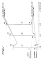
- the receiver dynamic range may be transposed by placing an attenuator between the antenna and the receiver. As attenuation increases, both the lowest and highest acceptable received signal strengths increase. Similarly, the receiver dynamic range is transposed downward as attenuation decreases. This influence of attenuation on dynamic range is illustrated in Figure 1. When attenuation is set at 0 decibels (dB), the receiver dynamic range 101 is defined by the sensitivity 102 and the blocking limit 103 of the receiver (not shown).
- the receiver dynamic range shifts to a new dynamic range 104, defined by sensitivity 105 and blocking limit 106, both of which are substantially 3 dB higher than the respective sensitivity 102 and blocking limit 103 that existed when attenuation is only 0 dB.
- the sensitivity 108 and blocking limit 109 are again increased, yielding a new receiver dynamic range 107.
- the distance between a mobile station and a base station can be very small. This can lead to disturbances in the receive band if there are large cells in the same area as the small cell. These large cells may belong to the same network as the small cell, or they may belong to another network operating in the same or an adjacent frequency band.
- the measure of these disturbances can be a bit error rate in digital communications systems. In analog systems, other signal quality measures can be used, such as total distortion of a modulated pilot tone.
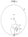
- FIG. 2 The situation just described is illustrated in Figure 2, in which a base station B 201 is associated with a cell 202, and a base station A 203 is associated with a cell 204. It will be observed that cell 204 is smaller than cell 202, and defines a geographical area that is located inside or near cell 202. Thus, because of the difference in the cells' relative sizes with respect to one another, cell 202 may be called a "macrocell” and cell 204 may be called a "microcell”.
- the base station A 203 receiver may experience disturbances from mobile station B 205. This may be so even if the radio frequencies used by base station A 203 are widely separated from those used by base station B 201 and mobile station B 205.
- base station A 203 is equipped with a dynamically adjustable attenuator interposed between the antenna and receiver as described above, the attenuation can be increased until the disturbance experienced by the receiver is acceptably low. This is because the disturbances in the receive band are attenuated with at least the value of the attenuator.
- the desired signal from mobile station A 206 which is transmitting to base station A 203, is also attenuated with the value of the attenuator. This may cause the signal from mobile station A 206 to be unacceptably low for reception by base station A 203.
- Applicants' invention provides a receiver that receives a communications signal from a transmitter, the received communications signal being attenuated at the receiver. The signal strength of the signal is then measured. This measured signal strength is then applied to a means for controlling the attenuation and to a means for controlling the transmission power.
- the attenuation control means dynamically controls the amount by which the received signal is attenuated.
- the transmission power control means generates a power control signal to be communicated to the transmitter.
- the transmitter uses the received power control signal to adjust the power level at which it transmits the communications signal to the receiver.
- Both the attenuation control means and the transmission control means control, respectively, receiver attenuation and transmission power level so as to optimize system performance.
- Receiver attenuation is adjusted so that the receiver sensitivity level is relatively high compared to a disturbance signal level, while at the same time transmission power level is adjusted so that the communications signal coming through the attenuator is still within the dynamic range of the receiver.
- receiver attenuation and transmission power level are adjusted to keep the attenuated signal within the dynamic range of the receiver. This feature is useful, for example, for designing a less expensive receiver having a reduced dynamic range which is compensated for by appropriate adjustment of receiver attenuation and transmission power level.
- the attenuator may include an antenna having a dynamically adjustable gain.
- Dynamic adjustment of receiver attenuation and transmission power level can be applied to a system in which a plurality of receivers are coupled to a common antenna through a multicoupler.
- a common attenuator is interposed between the common antenna and the multicoupler.
- Each receiver is also capable of further attenuating its received communications signal.
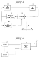
- Blocks to the right of the dotted line 301 are located in a mobile station. Blocks to the left of the dotted line 301 are located in a base station.
- Signals received at the base station by means of an antenna are input to a dynamically adjustable attenuator 302.
- the signal that is output from the attenuator 302 is input to a signal strength measurement circuit 303.
- the output of the signal strength measurement circuit 303 is coupled to the inputs of an attenuation control circuit 304, and to a mobile station power control circuit 305.
- the attenuation control circuit 304 is coupled to the attenuator 302 in order to control the amount of signal attenuation that occurs.
- the mobile station power control circuit 305 uses the output of the signal strength measurement circuit 303 in order to generate a signal that is communicated to a mobile station power circuit 306, where it controls the transmit power level of the mobile station.
- the signal strength measurements and power control functions are made in accordance with the European Telecommunications Standards Institute's (ETSI) Global System for Mobile Communications (GSM) standards.
- ETSI European Telecommunications Standards Institute's
- GSM Global System for Mobile Communications
- GSM recommendation 05.08 describes signal strength measurement in Sections 8.1.2 and 8.1.3. Sections 3.2-4.7, in conjunction with GSM recommendation 05.05 Section 4.1, describe RF power control.
- the control functions of the attenuation control circuit 304 and the mobile station power control circuit 305 are described in more detail below.
- One use of the dynamic control system depicted in Figure 3 is to compensate for the varying signal strength received by a base station B 201 (see Figure 2) that occurs when a mobile station B 205 travels within a large cell 202. If the transmit power of the mobile station B 205 is constant, the signal strength received by the base station B 201 decreases as the distance between the mobile station B 205 and the base station B 201 increases. Conversely, as the mobile station B 205 comes closer to the base station B 201, the received signal strength increases, assuming again that the transmit power of the mobile station 205 is constant.
- the present invention compensates for this as follows.
- the mobile station power control circuit 305 detects the diminution in received signal strength, and transmits a signal ordering the mobile station B 205 to transmit at a high power level. Due to the large path loss that occurs over this distance, the received signal strength in the base station B 201 may still be weak, and may be close to the receiver sensitivity level.
- the received signal strength in the base station B 201 increases. This is detected by the mobile station power control circuit 305, which responds by transmitting a signal to the mobile station B 205 which causes it to reduce its transmit power to a level that keeps the received signal strength within the receiver dynamic range. At some point, as the mobile station B 205 travels towards the base station B 201, the mobile station B 205 is transmitting at its lowest possible power level. As the mobile station B 205 continues towards the base station B 201, the received signal strength will increase, and after some time may be higher than is acceptable. In other words, despite the fact that the mobile station B 205 is transmitting at its lowest possible power level, its proximity to the base station B 201 causes the received signal strength to exceed the blocking limit of the receiver.
- the attenuation control circuit 304 which detects the unacceptably high received signal strength, and orders the attenuator 302 to increase the amount of attenuation.
- the upper limit of the acceptable signal strength i.e., the blocking limit
- Another problem that is solved by the present invention is the above-described situation that can occur when a small cell 204 is located inside, or near, a large cell 202.
- the disturbance in a base station A 203 caused by a mobile station B 205 that is attempting to transmit to a base station B 201 may be high, relative to the wanted signal being transmitted by the mobile station A 206.
- the mobile station power control circuit 305 detects the high level of disturbance, recognizable in digital communications systems, for example, as an increase in the bit error rate for the channel, and causes actions as follows.
- the attenuation control circuit 304 causes the attenuator 302 to increase its attenuation until the signal strength of the disturbance 110 (see Figure 1) is considerably reduced, possibly below the receiver sensitivity level 105.
- the desired carrier signal is also attenuated by this action.
- the mobile station power control circuit 305 transmits a signal to the power control circuit 306 of mobile station A 206, causing it to increase its transmit power level until the received signal strength of the carrier signal 111 (see Figure 1) is above the receiver sensitivity level 105.
- the received signal strength of the desired signal is kept constant above the sensitivity level while the disturbance is suppressed.
- the mobile station power control 305 could have been the first to act by ordering the mobile station A 206 to increase its transmit power level in order to increase the received signal strength accordingly, and thereby reduce the bit error rate.
- the attenuation control circuit 304 could then respond to this occurrence by increasing attenuation of the received signal to bring the received signal strength back down to a desired level.
- dynamic attenuation under the control of the attenuation control circuit 304 is combined with a mobile station power control process, carried out by the mobile station power control circuit 305, in which signal quality of the received signal is used to determine the transmit power.
- a mobile station power control process carried out by the mobile station power control circuit 305, in which signal quality of the received signal is used to determine the transmit power.
- a number of receivers 403 are shown coupled to a single antenna 401 by means of a receiver multicoupler 402.
- the receiver multicoupler 402 is a wideband amplifier that receives a broad band signal and has a plurality of narrow band signal outputs.
- Each receiver 403 may include the invention as described above with reference to Figure 3.
- the receiver multicoupler 402 may, itself, suffer blocking by strong signals that are input from the antenna 401. In that case, it is apparent that any attenuation that occurs within individual receivers 403 will be unable to eliminate this blocking.
- the receiver multicoupler 402 may be designed to have a higher blocking limit than any of the individual receivers 403.
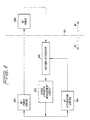
- FIG. 5 Another solution to the problem of blocking in the receiver multicoupler 402 is shown in Figure 5.
- attenuation is partitioned in order to achieve an optimum selection of attenuation before and after the receiver multicoupler 402.
- FIG. 5 One of a number N of receivers 503 is shown in Figure 5. Although the following description makes reference only to a single receiver 503, it should be understood that the description is applicable to each of the N receivers 503.
- Each receiver 503 has the control circuitry as described above with reference to Figure 3.
- the output of the signal strength measurement circuit 303 from each receiver 503 is coupled to an input of a base station front end attenuation control circuit 504.
- a signal representing the amount of attenuation being utilized by the respective receiver 503 is also output from the receiver's base station attenuation control circuit 505 and coupled to an input of the base station front end attenuation control circuit 504.
- the base station front end attenuation control circuit 504 combines these inputs with corresponding inputs from the other receivers 503 to determine the true signal strength of the signal that is being output from the front end attenuator 506. For example, these input signals to the base station front end attenuation control circuit 504 may simply be averaged. Other methods of determining the true signal strength of the signal that is being output from the front end attenuator 506 may also be used.
- the base station front end attenuation control circuit 504 then adjusts, by means of an output signal that is coupled to the front end attenuator 506, the strength of the signal that is input to the receiver multicoupler 502.
- the adjustment is such that the front end attenuation is kept as low as possible while still preventing blocking in the receiver multicoupler 502.
- the base station front end attenuation control circuit 504 must also have information regarding the dynamic range of the receiver multicoupler 502.
- the information pertaining to the dynamic range of the receiver multicoupler 502 should preferably be preprogrammed in the base station front end attenuation control circuit 504.
- each individual base station-mobile station link is regulated so as to produce an optimum balance of transmitted power and received signal quality.
- FIG. 6 an alternative embodiment of the invention is shown. This embodiment is very much like the one shown in Figure 3.
- the variable attenuator has been replaced by the antenna/attenuator 602, which is an antenna having adjustable antenna gain, such as an electronically adjustable phased array antenna.
- the remaining elements in Figure 6 operate the same as the corresponding elements described above with respect to Figure 3, and need not be described in further detail.
- IM intermodulation
- n the order of the intermodulation product.
- This makes it possible to implement a receiver/antenna configuration having an extreme robustness against radio environments having the kinds of disturbances discussed above, including high signal strength (causing blocking), and intermodulation products.
- system margins can be widened to improve performance in the presences of other types of disturbances, such as cochannel interference and propagation channel distortion.
Abstract
Description
- The present invention relates to a receiver and a method for receiving a communications signal according to the preamble of
claims 1 and 7, respectively. A receiver and a method of this kind are known from US 4 777 653. - In a typical telecommunications system, such as in a cellular telephone system, a receiver is designed to function with signals in a given signal strength range. This signal strength range is referred to as the dynamic range of the receiver. The lowest acceptable signal strength that can be received is called the receiver sensitivity. The highest acceptable signal strength that can be received is called the blocking limit.
- In a cellular telephone system, the distance between a base station (BS) and a mobile station (MS) varies as the mobile station moves around within a cell. Consequently, in large cells, the variations in received signal strength can be very large. Sometimes, these variations are so large that they cannot be compensated by varying the mobile station's transmit power. In such cells, it would be useful for the receiver dynamic range, that is, the signal level range defined by the highest and lowest acceptable received signal levels, to be changed/transposed in relation to the distance between the base station and the mobile station.
- The receiver dynamic range may be transposed by placing an attenuator between the antenna and the receiver. As attenuation increases, both the lowest and highest acceptable received signal strengths increase. Similarly, the receiver dynamic range is transposed downward as attenuation decreases. This influence of attenuation on dynamic range is illustrated in Figure 1. When attenuation is set at 0 decibels (dB), the receiver
dynamic range 101 is defined by thesensitivity 102 and theblocking limit 103 of the receiver (not shown). - If attenuation is increased to 3 dB, the receiver dynamic range shifts to a new
dynamic range 104, defined bysensitivity 105 andblocking limit 106, both of which are substantially 3 dB higher than therespective sensitivity 102 and blockinglimit 103 that existed when attenuation is only 0 dB. Similarly, if attenuation is increased to 6 dB, thesensitivity 108 andblocking limit 109 are again increased, yielding a new receiverdynamic range 107. - In small cells, the distance between a mobile station and a base station can be very small. This can lead to disturbances in the receive band if there are large cells in the same area as the small cell. These large cells may belong to the same network as the small cell, or they may belong to another network operating in the same or an adjacent frequency band. The measure of these disturbances can be a bit error rate in digital communications systems. In analog systems, other signal quality measures can be used, such as total distortion of a modulated pilot tone.
- The situation just described is illustrated in Figure 2, in which a
base station B 201 is associated with acell 202, and a base station A 203 is associated with acell 204. It will be observed thatcell 204 is smaller thancell 202, and defines a geographical area that is located inside or nearcell 202. Thus, because of the difference in the cells' relative sizes with respect to one another,cell 202 may be called a "macrocell" andcell 204 may be called a "microcell". When amobile station B 205, associated with the "macrocell" 202 comes near base station A 203, the base station A 203 receiver may experience disturbances frommobile station B 205. This may be so even if the radio frequencies used by base station A 203 are widely separated from those used bybase station B 201 and mobile station B 205. - If base station A 203 is equipped with a dynamically adjustable attenuator interposed between the antenna and receiver as described above, the attenuation can be increased until the disturbance experienced by the receiver is acceptably low. This is because the disturbances in the receive band are attenuated with at least the value of the attenuator. However, the desired signal from mobile station A 206, which is transmitting to base station A 203, is also attenuated with the value of the attenuator. This may cause the signal from mobile station A 206 to be unacceptably low for reception by base station A 203.
- The above described problem is solved in accordance with the Applicants' invention as defined in
claims 1 and 7. Advantageous embodiments are given in the dependent claims. - In one aspect, Applicants' invention provides a receiver that receives a communications signal from a transmitter, the received communications signal being attenuated at the receiver. The signal strength of the signal is then measured. This measured signal strength is then applied to a means for controlling the attenuation and to a means for controlling the transmission power. The attenuation control means dynamically controls the amount by which the received signal is attenuated.
- The transmission power control means generates a power control signal to be communicated to the transmitter. The transmitter uses the received power control signal to adjust the power level at which it transmits the communications signal to the receiver. Both the attenuation control means and the transmission control means control, respectively, receiver attenuation and transmission power level so as to optimize system performance.
- Receiver attenuation is adjusted so that the receiver sensitivity level is relatively high compared to a disturbance signal level, while at the same time transmission power level is adjusted so that the communications signal coming through the attenuator is still within the dynamic range of the receiver.
- Preferably, receiver attenuation and transmission power level are adjusted to keep the attenuated signal within the dynamic range of the receiver. This feature is useful, for example, for designing a less expensive receiver having a reduced dynamic range which is compensated for by appropriate adjustment of receiver attenuation and transmission power level.
- Preferably, the attenuator may include an antenna having a dynamically adjustable gain.
- Dynamic adjustment of receiver attenuation and transmission power level can be applied to a system in which a plurality of receivers are coupled to a common antenna through a multicoupler.
- A common attenuator is interposed between the common antenna and the multicoupler.
Each receiver is also capable of further attenuating its received communications signal. - These and other aspects of the invention will become apparent from the following description read in conjunction with the accompanying drawings in which:
- Figure 1 is a graph showing the dynamic range of a receiver as a function of attenuation;
- Figure 2 illustrates the situation of having a small mobile communications cell at least partly located within a large mobile communications cell;
- Figure 3 is a block diagram of an apparatus in accordance with the present invention for dynamically controlling receiver attenuation and transmitter power;
- Figure 4 is a block diagram of several receivers coupled to one antenna in accordance with another embodiment of the invention;
- Figure 5 is a block diagram of another embodiment of the invention which uses partitioned attenuation in a system having multiple receivers coupled to a common antenna by means of a multicoupler; and
- Figure 6 is a block diagram of an alternative embodiment of the invention in which an antenna and a variable attenuator have been combined in a common element.
-
- Referring now to Figure 3, a mobile telecommunications system incorporating the present invention is illustrated. Blocks to the right of the
dotted line 301 are located in a mobile station. Blocks to the left of thedotted line 301 are located in a base station. - Signals received at the base station by means of an antenna (not shown) are input to a dynamically
adjustable attenuator 302. The signal that is output from theattenuator 302 is input to a signalstrength measurement circuit 303. The output of the signalstrength measurement circuit 303 is coupled to the inputs of anattenuation control circuit 304, and to a mobile stationpower control circuit 305. Theattenuation control circuit 304 is coupled to theattenuator 302 in order to control the amount of signal attenuation that occurs. The mobile stationpower control circuit 305 uses the output of the signalstrength measurement circuit 303 in order to generate a signal that is communicated to a mobilestation power circuit 306, where it controls the transmit power level of the mobile station. In one preferred embodiment of the invention, the signal strength measurements and power control functions are made in accordance with the European Telecommunications Standards Institute's (ETSI) Global System for Mobile Communications (GSM) standards. - In particular, GSM recommendation 05.08 describes signal strength measurement in Sections 8.1.2 and 8.1.3. Sections 3.2-4.7, in conjunction with GSM recommendation 05.05 Section 4.1, describe RF power control. The control functions of the
attenuation control circuit 304 and the mobile stationpower control circuit 305 are described in more detail below. - One use of the dynamic control system depicted in Figure 3 is to compensate for the varying signal strength received by a base station B 201 (see Figure 2) that occurs when a
mobile station B 205 travels within alarge cell 202. If the transmit power of themobile station B 205 is constant, the signal strength received by thebase station B 201 decreases as the distance between themobile station B 205 and thebase station B 201 increases. Conversely, as themobile station B 205 comes closer to thebase station B 201, the received signal strength increases, assuming again that the transmit power of themobile station 205 is constant. - The present invention compensates for this as follows. When the
mobile station B 205 is situated near the border of thecell 202, the mobile stationpower control circuit 305 detects the diminution in received signal strength, and transmits a signal ordering themobile station B 205 to transmit at a high power level. Due to the large path loss that occurs over this distance, the received signal strength in thebase station B 201 may still be weak, and may be close to the receiver sensitivity level. - When the
mobile station B 205 moves towards thebase station B 201, the received signal strength in thebase station B 201 increases. This is detected by the mobile stationpower control circuit 305, which responds by transmitting a signal to themobile station B 205 which causes it to reduce its transmit power to a level that keeps the received signal strength within the receiver dynamic range. At some point, as themobile station B 205 travels towards thebase station B 201, themobile station B 205 is transmitting at its lowest possible power level. As themobile station B 205 continues towards thebase station B 201, the received signal strength will increase, and after some time may be higher than is acceptable. In other words, despite the fact that themobile station B 205 is transmitting at its lowest possible power level, its proximity to thebase station B 201 causes the received signal strength to exceed the blocking limit of the receiver. - This problem is solved in the present invention by the
attenuation control circuit 304, which detects the unacceptably high received signal strength, and orders theattenuator 302 to increase the amount of attenuation. The upper limit of the acceptable signal strength (i.e., the blocking limit) will then increase, thereby eliminating the problem with the high received signal strength. - Another problem that is solved by the present invention is the above-described situation that can occur when a
small cell 204 is located inside, or near, alarge cell 202. As explained above, the disturbance in abase station A 203 caused by amobile station B 205 that is attempting to transmit to abase station B 201 may be high, relative to the wanted signal being transmitted by themobile station A 206. - In accordance with the present invention, the mobile station
power control circuit 305 detects the high level of disturbance, recognizable in digital communications systems, for example, as an increase in the bit error rate for the channel, and causes actions as follows. Theattenuation control circuit 304 causes theattenuator 302 to increase its attenuation until the signal strength of the disturbance 110 (see Figure 1) is considerably reduced, possibly below thereceiver sensitivity level 105. However, the desired carrier signal is also attenuated by this action. To compensate for this, the mobile stationpower control circuit 305 transmits a signal to thepower control circuit 306 ofmobile station A 206, causing it to increase its transmit power level until the received signal strength of the carrier signal 111 (see Figure 1) is above thereceiver sensitivity level 105. Thus, the received signal strength of the desired signal is kept constant above the sensitivity level while the disturbance is suppressed. - It will be recognized by those skilled in the art that, in the above scenario, the mobile
station power control 305 could have been the first to act by ordering themobile station A 206 to increase its transmit power level in order to increase the received signal strength accordingly, and thereby reduce the bit error rate. Theattenuation control circuit 304 could then respond to this occurrence by increasing attenuation of the received signal to bring the received signal strength back down to a desired level. - In another feature of the invention, dynamic attenuation under the control of the
attenuation control circuit 304 is combined with a mobile station power control process, carried out by the mobile stationpower control circuit 305, in which signal quality of the received signal is used to determine the transmit power. By combining dynamic attenuation control with this kind of power control, unnecessary attenuation of the wanted signal is prevented when the disturbance is low. This has the advantage of keeping the mobile transmit power to a minimum, which is of great importance for many mobile applications. In one preferred embodiment, the mobile station power control process, in which signal quality of the received signal is used to determine the transmit power, is that which is described in U.S. Patent No. 5574982 entitled METHOD AND APPARATUS FOR TRANSMISSION POWER REGULATION IN A RADIO SYSTEM, filed in the name of Almgren et al. on May 14, 1993 and assigned to the assignee of this invention. - Frequently, a base station has several receivers coupled to the same receiver antenna. In such situations, the attenuation must be partitioned accordingly. Another embodiment of the invention that solves this problem will now be described with reference to Figures 4 and 5.
- In Figure 4, a number of
receivers 403 are shown coupled to asingle antenna 401 by means of areceiver multicoupler 402. Thereceiver multicoupler 402 is a wideband amplifier that receives a broad band signal and has a plurality of narrow band signal outputs. Eachreceiver 403 may include the invention as described above with reference to Figure 3. However, thereceiver multicoupler 402 may, itself, suffer blocking by strong signals that are input from theantenna 401. In that case, it is apparent that any attenuation that occurs withinindividual receivers 403 will be unable to eliminate this blocking. To avoid this problem, thereceiver multicoupler 402 may be designed to have a higher blocking limit than any of theindividual receivers 403. - Another solution to the problem of blocking in the
receiver multicoupler 402 is shown in Figure 5. Here, attenuation is partitioned in order to achieve an optimum selection of attenuation before and after thereceiver multicoupler 402. - One of a number N of
receivers 503 is shown in Figure 5. Although the following description makes reference only to asingle receiver 503, it should be understood that the description is applicable to each of theN receivers 503. Eachreceiver 503 has the control circuitry as described above with reference to Figure 3. In addition, the output of the signalstrength measurement circuit 303 from eachreceiver 503 is coupled to an input of a base station front endattenuation control circuit 504. - A signal representing the amount of attenuation being utilized by the
respective receiver 503 is also output from the receiver's base stationattenuation control circuit 505 and coupled to an input of the base station front endattenuation control circuit 504. The base station front endattenuation control circuit 504 combines these inputs with corresponding inputs from theother receivers 503 to determine the true signal strength of the signal that is being output from thefront end attenuator 506. For example, these input signals to the base station front endattenuation control circuit 504 may simply be averaged. Other methods of determining the true signal strength of the signal that is being output from thefront end attenuator 506 may also be used. - The base station front end
attenuation control circuit 504 then adjusts, by means of an output signal that is coupled to thefront end attenuator 506, the strength of the signal that is input to thereceiver multicoupler 502. The adjustment is such that the front end attenuation is kept as low as possible while still preventing blocking in thereceiver multicoupler 502. It will be recognized that in order to make this adjustment, the base station front endattenuation control circuit 504 must also have information regarding the dynamic range of thereceiver multicoupler 502. The information pertaining to the dynamic range of thereceiver multicoupler 502 should preferably be preprogrammed in the base station front endattenuation control circuit 504. - The rest of the regulation is accomplished as described above with reference to Figure 3. That is, each individual base station-mobile station link is regulated so as to produce an optimum balance of transmitted power and received signal quality.
- Referring now to Figure 6, an alternative embodiment of the invention is shown. This embodiment is very much like the one shown in Figure 3. The difference between the two embodiments is that, in Figure 6, the variable attenuator has been replaced by the antenna/
attenuator 602, which is an antenna having adjustable antenna gain, such as an electronically adjustable phased array antenna. The remaining elements in Figure 6 operate the same as the corresponding elements described above with respect to Figure 3, and need not be described in further detail. - The advantage of incorporating the adjustable attenuation directly in the antenna element is that intermodulation (IM) products generated in the antenna itself are attenuated by an amount that is approximately equal to the set attenuation raised to the nth power, where n is the order of the intermodulation product. This makes it possible to implement a receiver/antenna configuration having an extreme robustness against radio environments having the kinds of disturbances discussed above, including high signal strength (causing blocking), and intermodulation products. In addition, by designing a receiver which can compensate for high signal strength and intermodulation products, system margins can be widened to improve performance in the presences of other types of disturbances, such as cochannel interference and propagation channel distortion.
- The invention has been described with reference to several specific embodiments. It will be recognized by those skilled in the art, however, that the invention may be practiced in ways not illustrated here. Thus, the scope of the invention is not limited by this description, but is, instead, defined by the following claims.
Claims (7)
- A receiver (203) for receiving a communications signal (C) transmitted by a transmitter (206) and subject to disturbance, the transmitter (206) including transmitter power control means (306), responsive to a received power control signal, for controlling a power level at which the transmitter transmits the transmitted communications signal, said receiver comprisingcharacterized bymeasurement means (303) for generating a signal strength measurement signal based on the received communications signal;power control means (305), coupled to the measurement means (303), for generating a power control signal to be communicated to the transmitter (206); andmeans (305) for detecting a level of disturbance (110) in said communications signal transmitted by said transmitter (206) ;attenuating means (302) for attenuating the received communications signal by an attenuation amount;attenuation control means (304) coupled to the attenuating means (302), the measurement means (303) and the disturbance level detection means (305), for dynamically increasing said attenuation amount in response to an increase in said level of disturbance so as to reduce said detected level of disturbance;said power control means (305) being adapted to dynamically control the transmitter power level so as to keep the strength of said received attenuated communications signal above a sensitivity level (105) of said receiver so as to optimise communications system performance.
- The receiver according to claim 1, wherein said attenuation control means (304) and said power control means (305) are adapted to keep the attenuated signal within an effective dynamic range of the receiver.
- The receiver according to claim 1 or 2, wherein the attenuating means (302) includes an antenna (602) having a dynamically adjustable antenna gain.
- The receiver according to any one of the preceding claims, wherein said means for detecting a level of disturbance is adapted to detect a bit error rate of the received communication signal.
- The receiver according to any one of the preceding claims, wherein said power control means (305) is adapted to determine said transmitter power level depending on a detected signal quality of said received communications signal.
- A receiver apparatus havinga plurality of receivers (503) each according to any one of the preceding claims and each for receiving a communications signal transmitted by a corresponding one of a plurality of transmitters (206);a receiver multicoupler (502) having a signal input coupled to a common antenna (501) and a plurality (N) of signal outputs each coupled to one of the plurality of receivers (503); andfront end attenuating means (506) for attenuating the plurality of received communications signals by an amount dynamically determined by a front end attenuation control signal and for supplying the attenuated plurality of received communications signals to the receiver multicoupler (502);front end attenuation control means (504) coupled to the plurality of signal strength measurement means (303) of each of said receivers (503) for determining the signal strength of the signal output by said front end attenuating means (506) to said receiver multicoupler (502) and for supplying said front end attenuation control signal to the front end attenuating means (506);the front end attenuation control means (504) being adapted to dynamically control a receiver front end attenuation amount to prevent blocking in said receiver multicoupler (502) so as to substantially optimise communications system performance.
- A method for receiving a communications signal in a communications system having a receiver (203) that receives a communications signal transmitted by a transmitter (206), the transmitter (206) including transmitter power control means (306) responsive to a received power control signal for controlling a power level at which the transmitter (206) transmits the communications signal, the receiver (203) including attenuating means for attenuating the received communications signal by an amount dynamically determined by a control signal, the method comprising the steps of:characterized bymeasuring a signal strength of the received communications signal;generating a power control signal and communicating said power control signal to said transmitter;detecting a level of disturbance in said communications signal transmitted by said transmitter (206);attenuating the received communications signal by an amount dynamically adjusted based on the measured signal strength and in response to an increase in the detected level of disturbance so as to reduce said level of disturbance; anddynamically controlling the transmitter power level so as to keep the strength of said received attenuated communications signal above a sensitivity level (105) of said receiver so as to optimise communications system performance.
Applications Claiming Priority (3)
| Application Number | Priority Date | Filing Date | Title |
|---|---|---|---|
| US61043 | 1993-05-14 | ||
| US08/061,043 US5669066A (en) | 1993-05-14 | 1993-05-14 | Dynamic control of transmitting power at a transmitter and attenuation at a receiver |
| PCT/SE1994/000435 WO1994027381A1 (en) | 1993-05-14 | 1994-05-10 | Dynamic control of transmitting power at a transmitter and attenuation at a receiver |
Publications (2)
| Publication Number | Publication Date |
|---|---|
| EP0650648A1 EP0650648A1 (en) | 1995-05-03 |
| EP0650648B1 true EP0650648B1 (en) | 2002-12-11 |
Family
ID=22033278
Family Applications (1)
| Application Number | Title | Priority Date | Filing Date |
|---|---|---|---|
| EP94916452A Expired - Lifetime EP0650648B1 (en) | 1993-05-14 | 1994-05-10 | Dynamic control of transmitting power at a transmitter and attenuation at a receiver |
Country Status (21)
| Country | Link |
|---|---|
| US (1) | US5669066A (en) |
| EP (1) | EP0650648B1 (en) |
| JP (1) | JPH07509114A (en) |
| KR (1) | KR100341069B1 (en) |
| CN (1) | CN1076906C (en) |
| AT (1) | ATE229712T1 (en) |
| AU (1) | AU680256B2 (en) |
| CA (1) | CA2139769A1 (en) |
| DE (1) | DE69431864T2 (en) |
| ES (1) | ES2183838T3 (en) |
| FI (1) | FI950158A (en) |
| MY (1) | MY110864A (en) |
| NO (1) | NO950102D0 (en) |
| NZ (1) | NZ266552A (en) |
| PH (1) | PH31695A (en) |
| RU (1) | RU2120183C1 (en) |
| SG (1) | SG48937A1 (en) |
| TR (1) | TR27830A (en) |
| TW (1) | TW325610B (en) |
| WO (1) | WO1994027381A1 (en) |
| ZA (1) | ZA943308B (en) |
Families Citing this family (48)
| Publication number | Priority date | Publication date | Assignee | Title |
|---|---|---|---|---|
| JP2785804B2 (en) * | 1996-05-30 | 1998-08-13 | 日本電気株式会社 | Mobile communication system |
| US5926747A (en) * | 1996-09-05 | 1999-07-20 | Airnet Communications Corp. | Method and apparatus for dynamically optimizing the forward-link transmit power of a broadband multi-carrier radio signal |
| KR100193842B1 (en) * | 1996-09-13 | 1999-06-15 | 윤종용 | Power Control Circuit and Method of Wireless Communication System |
| US6236863B1 (en) * | 1997-03-31 | 2001-05-22 | Oki Telecom, Inc. | Comprehensive transmitter power control system for radio telephones |
| JP3833787B2 (en) * | 1997-08-07 | 2006-10-18 | 富士通株式会社 | Base station transceiver |
| WO1999023778A1 (en) * | 1997-11-04 | 1999-05-14 | Motorola Inc. | Method and apparatus for reducing the effect of a fading condition in a communications system |
| US6154638A (en) * | 1998-01-16 | 2000-11-28 | Lucent Technologies Inc. | Methods and apparatus for determining forward and reverse link performance in a wireless communication system |
| US6236726B1 (en) * | 1998-02-27 | 2001-05-22 | Nortel Networks Limited | Transmit power scaling for far-end crosstalk reduction |
| US6233438B1 (en) * | 1998-03-26 | 2001-05-15 | Ericsson Inc. | Wide-range power control systems and methods for radio frequency transmitters and mobile radiotelephones |
| US6377555B1 (en) | 1998-09-22 | 2002-04-23 | Jhong Sam Lee | Method for determining forward link channel powers for a CDMA cellular or PCS system |
| DE19923580B4 (en) * | 1999-05-21 | 2006-03-02 | Robert Bosch Gmbh | Method and device for power control of a transmitter |
| JP3392077B2 (en) * | 1999-08-05 | 2003-03-31 | シャープ株式会社 | Cable modem with wireless communication function |
| US6519449B1 (en) * | 1999-10-29 | 2003-02-11 | Nortel Networks Limited | Method and apparatus for a signal power control in a wireless communication system |
| US6650904B1 (en) * | 1999-12-16 | 2003-11-18 | Ericsson Inc. | Optimization of radio receiver uplink power |
| US7366133B1 (en) * | 1999-12-30 | 2008-04-29 | Aperto Networks, Inc. | Integrated, self-optimizing, multi-parameter/multi-variable point-to-multipoint communication system [II] |
| US6650623B1 (en) * | 1999-12-30 | 2003-11-18 | Aperto Networks, Inc. | Adaptive link layer for point to multipoint communication system |
| US6654384B1 (en) | 1999-12-30 | 2003-11-25 | Aperto Networks, Inc. | Integrated self-optimizing multi-parameter and multi-variable point to multipoint communication system |
| FI20000539A (en) * | 2000-03-09 | 2001-09-10 | Nokia Networks Oy | A method for minimizing interference effects and a radio system |
| US6636488B1 (en) * | 2000-10-11 | 2003-10-21 | Aperto Networks, Inc. | Automatic retransmission and error recovery for packet oriented point-to-multipoint communication |
| US6748196B2 (en) * | 2001-01-30 | 2004-06-08 | Kon-Hee Lee | Transmit output controlling circuit and method of a wireless mobile communication system |
| GB0219170D0 (en) * | 2002-08-16 | 2002-09-25 | Univ Surrey | Wireless communication system and a method of operating a wireless communication system |
| CA2501117A1 (en) * | 2002-10-03 | 2004-04-15 | Interdigital Technology Corporation | Determination of code transmit power range in downlink power control for cellular systems |
| US8452316B2 (en) | 2004-06-18 | 2013-05-28 | Qualcomm Incorporated | Power control for a wireless communication system utilizing orthogonal multiplexing |
| US7197692B2 (en) | 2004-06-18 | 2007-03-27 | Qualcomm Incorporated | Robust erasure detection and erasure-rate-based closed loop power control |
| US7594151B2 (en) | 2004-06-18 | 2009-09-22 | Qualcomm, Incorporated | Reverse link power control in an orthogonal system |
| US7747271B2 (en) | 2005-03-02 | 2010-06-29 | Qualcomm Incorporated | Radiated power control for a multi-antenna transmission |
| US8848574B2 (en) | 2005-03-15 | 2014-09-30 | Qualcomm Incorporated | Interference control in a wireless communication system |
| US8942639B2 (en) | 2005-03-15 | 2015-01-27 | Qualcomm Incorporated | Interference control in a wireless communication system |
| WO2007050926A2 (en) | 2005-10-27 | 2007-05-03 | Qualcomm Incorporated | Method and apparatus for estimating reverse link loading in a wireless communication system |
| US7929934B2 (en) * | 2006-02-15 | 2011-04-19 | Toshiba Tec Kabushiki Kaisha | Identification information reader and printer including the same |
| RU2420879C2 (en) * | 2006-09-08 | 2011-06-10 | Квэлкомм Инкорпорейтед | Method and device for corrections for controlling power based on delta value of wireless communication systems |
| US8442572B2 (en) | 2006-09-08 | 2013-05-14 | Qualcomm Incorporated | Method and apparatus for adjustments for delta-based power control in wireless communication systems |
| US8670777B2 (en) | 2006-09-08 | 2014-03-11 | Qualcomm Incorporated | Method and apparatus for fast other sector interference (OSI) adjustment |
| WO2008050998A1 (en) * | 2006-10-23 | 2008-05-02 | Samsung Electronics Co., Ltd. | Method for setting transmission power of data channel in a frequency division multiple access system and mobile station apparatus for the same |
| US8676223B2 (en) | 2007-03-23 | 2014-03-18 | Qualcomm Incorporated | Backhaul communication for interference management |
| US7957757B2 (en) | 2007-07-05 | 2011-06-07 | Qualcomm Incorporated | Open loop power offset update |
| US8712461B2 (en) | 2007-08-10 | 2014-04-29 | Qualcomm Incorporated | Autonomous adaptation of transmit power |
| US8412255B2 (en) * | 2007-09-20 | 2013-04-02 | Qualcomm Incorporated | Reverse link traffic power control |
| US9037155B2 (en) | 2008-10-28 | 2015-05-19 | Sven Fischer | Time of arrival (TOA) estimation for positioning in a wireless communication network |
| US8982851B2 (en) | 2009-01-06 | 2015-03-17 | Qualcomm Incorporated | Hearability improvements for reference signals |
| US8670432B2 (en) * | 2009-06-22 | 2014-03-11 | Qualcomm Incorporated | Methods and apparatus for coordination of sending reference signals from multiple cells |
| US8433359B2 (en) * | 2009-12-03 | 2013-04-30 | Intel Corporation | Uplink power control scheme |
| US9091746B2 (en) | 2010-07-01 | 2015-07-28 | Qualcomm Incorporated | Determination of positions of wireless transceivers to be added to a wireless communication network |
| KR101045760B1 (en) | 2011-04-08 | 2011-07-01 | 주식회사텔레맥스 | An active radio antenna divider for vhf using a directional coupler |
| US20140098073A1 (en) * | 2012-10-05 | 2014-04-10 | Research In Motion Limited | Method and apparatus pertaining to user-sensed transmission power control in a stylus |
| US9867143B1 (en) * | 2013-03-15 | 2018-01-09 | Icontrol Networks, Inc. | Adaptive Power Modulation |
| US10042039B2 (en) * | 2014-04-02 | 2018-08-07 | Vayyar Imaging Ltd | Device system and method for dynamic signal measurement range scaling |
| CN107257245B (en) * | 2017-06-15 | 2020-01-21 | 海能达通信股份有限公司 | Anti-interference transmitting and receiving unit, transmitting and receiving device and anti-interference attenuation processing method |
Family Cites Families (19)
| Publication number | Priority date | Publication date | Assignee | Title |
|---|---|---|---|---|
| US2543973A (en) * | 1946-06-27 | 1951-03-06 | United Air Lines Inc | Plural-frequency coupling unit |
| US3139584A (en) * | 1962-05-24 | 1964-06-30 | Collins Radio Co | Signal input overload protection attenuation circuit for transistor receivers |
| US3143706A (en) * | 1962-05-31 | 1964-08-04 | Collins Radio Co | Radio receiver input protective selfactuated variable attenuator |
| US3577103A (en) * | 1969-04-01 | 1971-05-04 | Zenith Radio Corp | Variable attenuator for a wave signal receiver |
| US4119972A (en) * | 1977-02-03 | 1978-10-10 | Nasa | Phased array antenna control |
| JPH0117855Y2 (en) * | 1980-05-19 | 1989-05-24 | ||
| US4531234A (en) * | 1983-02-14 | 1985-07-23 | International Jensen Incorporated | Optimizing antenna interface for automobile radio receivers |
| JPS59157575A (en) * | 1983-02-27 | 1984-09-06 | Anritsu Corp | Spectrum analyzer |
| US4613990A (en) * | 1984-06-25 | 1986-09-23 | At&T Bell Laboratories | Radiotelephone transmission power control |
| JPS6143026A (en) * | 1984-08-06 | 1986-03-01 | Nippon Telegr & Teleph Corp <Ntt> | System for controlling and transmitting received electric field |
| US4661993A (en) * | 1984-10-12 | 1987-04-28 | At&T Company | Technique for improving radio system performance during fading |
| JPS61210728A (en) * | 1985-03-14 | 1986-09-18 | Alps Electric Co Ltd | Output power control device for transmitter |
| JPS62128231A (en) * | 1985-11-28 | 1987-06-10 | Toshiba Corp | Tuner circuit |
| FR2592256B1 (en) * | 1985-12-20 | 1988-02-12 | Trt Telecom Radio Electr | DEVICE FOR CONTROLLING THE TRANSMIT POWER OF A RADIO BEAM |
| US4739516A (en) * | 1986-01-17 | 1988-04-19 | A. Van Brackel & Sons, Inc. | Frequency tuned antenna assembly |
| JPS647722A (en) * | 1987-06-30 | 1989-01-11 | Nec Corp | Transmitting power control system |
| JPH02203625A (en) * | 1989-02-02 | 1990-08-13 | Fujitsu Ltd | Transmission power control method |
| JP2769478B2 (en) * | 1989-04-10 | 1998-06-25 | 三菱電機株式会社 | transceiver |
| JPH03198526A (en) * | 1989-12-27 | 1991-08-29 | Nec Corp | Transmission power control system |
-
1993
- 1993-05-14 US US08/061,043 patent/US5669066A/en not_active Expired - Lifetime
-
1994
- 1994-05-10 AT AT94916452T patent/ATE229712T1/en not_active IP Right Cessation
- 1994-05-10 WO PCT/SE1994/000435 patent/WO1994027381A1/en active IP Right Grant
- 1994-05-10 JP JP6525329A patent/JPH07509114A/en active Pending
- 1994-05-10 RU RU95105526A patent/RU2120183C1/en active
- 1994-05-10 KR KR1019950700143A patent/KR100341069B1/en not_active IP Right Cessation
- 1994-05-10 ES ES94916452T patent/ES2183838T3/en not_active Expired - Lifetime
- 1994-05-10 EP EP94916452A patent/EP0650648B1/en not_active Expired - Lifetime
- 1994-05-10 SG SG1996003870A patent/SG48937A1/en unknown
- 1994-05-10 DE DE69431864T patent/DE69431864T2/en not_active Expired - Lifetime
- 1994-05-10 AU AU68101/94A patent/AU680256B2/en not_active Expired
- 1994-05-10 NZ NZ266552A patent/NZ266552A/en unknown
- 1994-05-10 CA CA002139769A patent/CA2139769A1/en not_active Abandoned
- 1994-05-10 CN CN94190289A patent/CN1076906C/en not_active Expired - Lifetime
- 1994-05-13 PH PH48270A patent/PH31695A/en unknown
- 1994-05-13 ZA ZA943308A patent/ZA943308B/en unknown
- 1994-05-13 MY MYPI94001197A patent/MY110864A/en unknown
- 1994-05-14 TW TW083104476A patent/TW325610B/en not_active IP Right Cessation
- 1994-05-16 TR TR00543/94A patent/TR27830A/en unknown
-
1995
- 1995-01-10 NO NO950102A patent/NO950102D0/en not_active Application Discontinuation
- 1995-01-13 FI FI950158A patent/FI950158A/en unknown
Also Published As
| Publication number | Publication date |
|---|---|
| KR950702766A (en) | 1995-07-29 |
| NO950102L (en) | 1995-01-10 |
| MY110864A (en) | 1999-05-31 |
| JPH07509114A (en) | 1995-10-05 |
| ATE229712T1 (en) | 2002-12-15 |
| CN1109701A (en) | 1995-10-04 |
| EP0650648A1 (en) | 1995-05-03 |
| ES2183838T3 (en) | 2003-04-01 |
| DE69431864D1 (en) | 2003-01-23 |
| NO950102D0 (en) | 1995-01-10 |
| TW325610B (en) | 1998-01-21 |
| ZA943308B (en) | 1995-01-16 |
| CA2139769A1 (en) | 1994-11-24 |
| RU2120183C1 (en) | 1998-10-10 |
| DE69431864T2 (en) | 2003-07-17 |
| SG48937A1 (en) | 1998-05-18 |
| AU6810194A (en) | 1994-12-12 |
| NZ266552A (en) | 1997-06-24 |
| AU680256B2 (en) | 1997-07-24 |
| US5669066A (en) | 1997-09-16 |
| PH31695A (en) | 1999-01-18 |
| FI950158A0 (en) | 1995-01-13 |
| KR100341069B1 (en) | 2002-11-13 |
| WO1994027381A1 (en) | 1994-11-24 |
| CN1076906C (en) | 2001-12-26 |
| FI950158A (en) | 1995-01-13 |
| TR27830A (en) | 1995-08-31 |
Similar Documents
| Publication | Publication Date | Title |
|---|---|---|
| EP0650648B1 (en) | Dynamic control of transmitting power at a transmitter and attenuation at a receiver | |
| US7003310B1 (en) | Coupled uplink/downlink power control and spatial processing with adaptive antenna arrays | |
| CA2169646C (en) | Method and apparatus for balancing the forward link handoff boundary to the reverse link handoff boundary in a cellular communication system | |
| EP0762668B1 (en) | Method for controlling transmission power of a radio transmitter | |
| AU673576B2 (en) | Access burst power control | |
| CN100459755C (en) | Mobile terminal with power control and method | |
| KR100215947B1 (en) | Transmitting power control method in cdma | |
| US6473624B1 (en) | Determining a reference power level for diversity handover base stations | |
| US7151740B2 (en) | Transmit power control for an OFDM-based wireless communication system | |
| EP1169785B1 (en) | Adaptive power control in a mobile radio communications system | |
| JP3782616B2 (en) | Booster, monitoring device, booster system, control method and monitoring method | |
| US6334050B1 (en) | Arrangement and a method relating to a radio unit | |
| US6594499B1 (en) | Downlink power control in a cellular telecommunications network | |
| EP0569504B1 (en) | Intermodulation compensation in a receiver | |
| US6137994A (en) | Radio communication system and method for setting an output power of a base site therein | |
| US6430173B1 (en) | Reception method and receiver | |
| US6701157B2 (en) | Transmitter circuit architecture and method for reducing in-band noise in point to multipoint communication systems | |
| KR101014465B1 (en) | Adaptation of the communication between a mobile station and a first base station, based on an estimation of the interference that occurs in a second base station caused by the signal of the mobile station | |
| JPH0870274A (en) | Mobile communication system and mobile station equipment | |
| AU701240C (en) | Method and apparatus for balancing the forward link handoff boundary to the reverse link handoff boundary in a cellular communication system | |
| JPH09270715A (en) | Transmission circuit and initialization method for the circuit | |
| MXPA99011473A (en) | An arrangement and a method relating to a radio unit |
Legal Events
| Date | Code | Title | Description |
|---|---|---|---|
| PUAI | Public reference made under article 153(3) epc to a published international application that has entered the european phase |
Free format text: ORIGINAL CODE: 0009012 |
|
| 17P | Request for examination filed |
Effective date: 19941207 |
|
| AK | Designated contracting states |
Kind code of ref document: A1 Designated state(s): AT BE CH DE DK ES FR GB GR IE IT LI LU NL PT SE |
|
| 17Q | First examination report despatched |
Effective date: 19980902 |
|
| GRAG | Despatch of communication of intention to grant |
Free format text: ORIGINAL CODE: EPIDOS AGRA |
|
| GRAG | Despatch of communication of intention to grant |
Free format text: ORIGINAL CODE: EPIDOS AGRA |
|
| GRAH | Despatch of communication of intention to grant a patent |
Free format text: ORIGINAL CODE: EPIDOS IGRA |
|
| GRAH | Despatch of communication of intention to grant a patent |
Free format text: ORIGINAL CODE: EPIDOS IGRA |
|
| GRAA | (expected) grant |
Free format text: ORIGINAL CODE: 0009210 |
|
| AK | Designated contracting states |
Kind code of ref document: B1 Designated state(s): AT BE CH DE DK ES FR GB GR IE IT LI LU NL PT SE |
|
| PG25 | Lapsed in a contracting state [announced via postgrant information from national office to epo] |
Ref country code: NL Free format text: LAPSE BECAUSE OF FAILURE TO SUBMIT A TRANSLATION OF THE DESCRIPTION OR TO PAY THE FEE WITHIN THE PRESCRIBED TIME-LIMIT Effective date: 20021211 Ref country code: LI Free format text: LAPSE BECAUSE OF FAILURE TO SUBMIT A TRANSLATION OF THE DESCRIPTION OR TO PAY THE FEE WITHIN THE PRESCRIBED TIME-LIMIT Effective date: 20021211 Ref country code: GR Free format text: LAPSE BECAUSE OF FAILURE TO SUBMIT A TRANSLATION OF THE DESCRIPTION OR TO PAY THE FEE WITHIN THE PRESCRIBED TIME-LIMIT Effective date: 20021211 Ref country code: CH Free format text: LAPSE BECAUSE OF FAILURE TO SUBMIT A TRANSLATION OF THE DESCRIPTION OR TO PAY THE FEE WITHIN THE PRESCRIBED TIME-LIMIT Effective date: 20021211 Ref country code: BE Free format text: LAPSE BECAUSE OF FAILURE TO SUBMIT A TRANSLATION OF THE DESCRIPTION OR TO PAY THE FEE WITHIN THE PRESCRIBED TIME-LIMIT Effective date: 20021211 Ref country code: AT Free format text: LAPSE BECAUSE OF FAILURE TO SUBMIT A TRANSLATION OF THE DESCRIPTION OR TO PAY THE FEE WITHIN THE PRESCRIBED TIME-LIMIT Effective date: 20021211 |
|
| REF | Corresponds to: |
Ref document number: 229712 Country of ref document: AT Date of ref document: 20021215 Kind code of ref document: T |
|
| REG | Reference to a national code |
Ref country code: GB Ref legal event code: FG4D |
|
| REG | Reference to a national code |
Ref country code: CH Ref legal event code: EP |
|
| REG | Reference to a national code |
Ref country code: IE Ref legal event code: FG4D |
|
| REF | Corresponds to: |
Ref document number: 69431864 Country of ref document: DE Date of ref document: 20030123 |
|
| PG25 | Lapsed in a contracting state [announced via postgrant information from national office to epo] |
Ref country code: SE Free format text: LAPSE BECAUSE OF FAILURE TO SUBMIT A TRANSLATION OF THE DESCRIPTION OR TO PAY THE FEE WITHIN THE PRESCRIBED TIME-LIMIT Effective date: 20030311 Ref country code: PT Free format text: LAPSE BECAUSE OF FAILURE TO SUBMIT A TRANSLATION OF THE DESCRIPTION OR TO PAY THE FEE WITHIN THE PRESCRIBED TIME-LIMIT Effective date: 20030311 Ref country code: DK Free format text: LAPSE BECAUSE OF FAILURE TO SUBMIT A TRANSLATION OF THE DESCRIPTION OR TO PAY THE FEE WITHIN THE PRESCRIBED TIME-LIMIT Effective date: 20030311 |
|
| REG | Reference to a national code |
Ref country code: ES Ref legal event code: FG2A Ref document number: 2183838 Country of ref document: ES Kind code of ref document: T3 |
|
| NLV1 | Nl: lapsed or annulled due to failure to fulfill the requirements of art. 29p and 29m of the patents act | ||
| ET | Fr: translation filed | ||
| PG25 | Lapsed in a contracting state [announced via postgrant information from national office to epo] |
Ref country code: LU Free format text: LAPSE BECAUSE OF NON-PAYMENT OF DUE FEES Effective date: 20030510 |
|
| PG25 | Lapsed in a contracting state [announced via postgrant information from national office to epo] |
Ref country code: IE Free format text: LAPSE BECAUSE OF NON-PAYMENT OF DUE FEES Effective date: 20030512 |
|
| REG | Reference to a national code |
Ref country code: CH Ref legal event code: PL |
|
| PLBE | No opposition filed within time limit |
Free format text: ORIGINAL CODE: 0009261 |
|
| STAA | Information on the status of an ep patent application or granted ep patent |
Free format text: STATUS: NO OPPOSITION FILED WITHIN TIME LIMIT |
|
| 26N | No opposition filed |
Effective date: 20030912 |
|
| REG | Reference to a national code |
Ref country code: IE Ref legal event code: MM4A |
|
| REG | Reference to a national code |
Ref country code: HK Ref legal event code: WD Ref document number: 1014100 Country of ref document: HK |
|
| PGFP | Annual fee paid to national office [announced via postgrant information from national office to epo] |
Ref country code: ES Payment date: 20120528 Year of fee payment: 19 |
|
| PGFP | Annual fee paid to national office [announced via postgrant information from national office to epo] |
Ref country code: GB Payment date: 20130528 Year of fee payment: 20 Ref country code: DE Payment date: 20130530 Year of fee payment: 20 |
|
| PGFP | Annual fee paid to national office [announced via postgrant information from national office to epo] |
Ref country code: IT Payment date: 20130524 Year of fee payment: 20 Ref country code: FR Payment date: 20130606 Year of fee payment: 20 |
|
| REG | Reference to a national code |
Ref country code: DE Ref legal event code: R071 Ref document number: 69431864 Country of ref document: DE |
|
| REG | Reference to a national code |
Ref country code: GB Ref legal event code: PE20 Expiry date: 20140509 |
|
| PG25 | Lapsed in a contracting state [announced via postgrant information from national office to epo] |
Ref country code: GB Free format text: LAPSE BECAUSE OF EXPIRATION OF PROTECTION Effective date: 20140509 |
|
| PG25 | Lapsed in a contracting state [announced via postgrant information from national office to epo] |
Ref country code: DE Free format text: LAPSE BECAUSE OF EXPIRATION OF PROTECTION Effective date: 20140513 |
|
| REG | Reference to a national code |
Ref country code: ES Ref legal event code: FD2A Effective date: 20140926 |
|
| PG25 | Lapsed in a contracting state [announced via postgrant information from national office to epo] |
Ref country code: ES Free format text: LAPSE BECAUSE OF EXPIRATION OF PROTECTION Effective date: 20140511 |