EP0652576A2 - Method of manufacturing solid electrolytic capacitor - Google Patents
Method of manufacturing solid electrolytic capacitor Download PDFInfo
- Publication number
- EP0652576A2 EP0652576A2 EP94117352A EP94117352A EP0652576A2 EP 0652576 A2 EP0652576 A2 EP 0652576A2 EP 94117352 A EP94117352 A EP 94117352A EP 94117352 A EP94117352 A EP 94117352A EP 0652576 A2 EP0652576 A2 EP 0652576A2
- Authority
- EP
- European Patent Office
- Prior art keywords
- polymer compound
- compound layer
- conductive polymer
- forming
- conductive
- Prior art date
- Legal status (The legal status is an assumption and is not a legal conclusion. Google has not performed a legal analysis and makes no representation as to the accuracy of the status listed.)
- Granted
Links
Images

Classifications
-
- H—ELECTRICITY
- H01—ELECTRIC ELEMENTS
- H01G—CAPACITORS; CAPACITORS, RECTIFIERS, DETECTORS, SWITCHING DEVICES OR LIGHT-SENSITIVE DEVICES, OF THE ELECTROLYTIC TYPE
- H01G9/00—Electrolytic capacitors, rectifiers, detectors, switching devices, light-sensitive or temperature-sensitive devices; Processes of their manufacture
- H01G9/004—Details
- H01G9/022—Electrolytes; Absorbents
- H01G9/025—Solid electrolytes
-
- H—ELECTRICITY
- H01—ELECTRIC ELEMENTS
- H01G—CAPACITORS; CAPACITORS, RECTIFIERS, DETECTORS, SWITCHING DEVICES OR LIGHT-SENSITIVE DEVICES, OF THE ELECTROLYTIC TYPE
- H01G11/00—Hybrid capacitors, i.e. capacitors having different positive and negative electrodes; Electric double-layer [EDL] capacitors; Processes for the manufacture thereof or of parts thereof
- H01G11/22—Electrodes
- H01G11/30—Electrodes characterised by their material
- H01G11/48—Conductive polymers
-
- H—ELECTRICITY
- H01—ELECTRIC ELEMENTS
- H01G—CAPACITORS; CAPACITORS, RECTIFIERS, DETECTORS, SWITCHING DEVICES OR LIGHT-SENSITIVE DEVICES, OF THE ELECTROLYTIC TYPE
- H01G11/00—Hybrid capacitors, i.e. capacitors having different positive and negative electrodes; Electric double-layer [EDL] capacitors; Processes for the manufacture thereof or of parts thereof
- H01G11/54—Electrolytes
- H01G11/56—Solid electrolytes, e.g. gels; Additives therein
-
- H—ELECTRICITY
- H01—ELECTRIC ELEMENTS
- H01G—CAPACITORS; CAPACITORS, RECTIFIERS, DETECTORS, SWITCHING DEVICES OR LIGHT-SENSITIVE DEVICES, OF THE ELECTROLYTIC TYPE
- H01G9/00—Electrolytic capacitors, rectifiers, detectors, switching devices, light-sensitive or temperature-sensitive devices; Processes of their manufacture
- H01G9/004—Details
- H01G9/022—Electrolytes; Absorbents
- H01G9/025—Solid electrolytes
- H01G9/028—Organic semiconducting electrolytes, e.g. TCNQ
-
- Y—GENERAL TAGGING OF NEW TECHNOLOGICAL DEVELOPMENTS; GENERAL TAGGING OF CROSS-SECTIONAL TECHNOLOGIES SPANNING OVER SEVERAL SECTIONS OF THE IPC; TECHNICAL SUBJECTS COVERED BY FORMER USPC CROSS-REFERENCE ART COLLECTIONS [XRACs] AND DIGESTS
- Y02—TECHNOLOGIES OR APPLICATIONS FOR MITIGATION OR ADAPTATION AGAINST CLIMATE CHANGE
- Y02E—REDUCTION OF GREENHOUSE GAS [GHG] EMISSIONS, RELATED TO ENERGY GENERATION, TRANSMISSION OR DISTRIBUTION
- Y02E60/00—Enabling technologies; Technologies with a potential or indirect contribution to GHG emissions mitigation
- Y02E60/13—Energy storage using capacitors
Definitions
- the present invention relates to a method of manufacturing a solid electrolytic capacitor and, more particularly, to a method of manufacturing a solid electrolytic capacitor using a conductive polymer compound as a solid electrolyte.
- a general solid electrolytic capacitor has a structure in which a molded porous body consisting of a valve metal such as tantalum or aluminum is used as an anode, an oxide coating of the valve metal is used as a dielectric, and a solid electrolyte such as manganese dioxide or a 7,7,8,8-tetracyanoquinodimethane (TCNQ) complex salt serves as part of a cathode.
- a solid electrolyte such as manganese dioxide or a 7,7,8,8-tetracyanoquinodimethane (TCNQ) complex salt serves as part of a cathode.
- TCNQ 7,7,8,8-tetracyanoquinodimethane
- a solid electrolytic capacitor manufactured by the following method is disclosed in Japanese Patent Laid-Open No. 3-35516 (Reference 1). That is, polymerized polyaniline soluble in an organic solvent is coated on a dielectric oxide coating, dried, and then doped with proton acid to make the polyaniline conductive. According to this method, a polyaniline film having a large thickness can be formed.
- the polyaniline solution used in the method cannot satisfactorily permeate the entire fine uneven surface of the dielectric oxide coating because the polyaniline solution has a very high viscosity. Therefore, only a capacitor having a considerably low capacitance reproduction ratio (i.e., the ratio of an actual electrostatic capacitance value to a design value) can be disadvantageously manufactured.
- a solid electrolytic capacitor in which a conductive polymer compound obtained by polymerization on a dielectric oxide coating using an oxidant is used as a solid electrolyte has a thin solid electrolyte layer. Therefore, the dielectric oxide coating is damaged by thermal stress generated upon mounting the solid electrolytic capacitor, thereby disadvantageously increasing a leakage current.
- a polyaniline solution cannot permeate the entire fine uneven surface of the dielectric oxide coating because the polyaniline solution has a very high viscosity. Therefore, only a capacitor having a very low capacitance reproduction ratio can be disadvantageously manufactured.
- a method of manufacturing a solid electrolytic capacitor which simultaneously solves the above-described two problems has not been developed.
- a method of manufacturing a solid electrolytic capacitor comprising the step of oxidizing a surface of an anode consisting of a valve metal and having a lead extending therefrom to form a dielectric layer, the step of forming a first conductive polymer compound layer on the dielectric layer, the step including a chemical oxidation and polymerization process using an oxidant the step of forming an undoped polymer compound layer on the first conductive polymer compound layer using a solution containing a polymer compound polymerized in advance and soluble in an organic solvent, and then doping proton acid in the undoped polymer compound layer to make the undoped polymer compound layer conductive, thereby forming a second conductive polymer compound layer, and the step of forming a cathode electrode on the second conductive polymer compound layer.
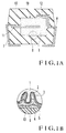
- Fig. 1A shows an embodiment of a solid electrolytic capacitor according to the present invention
- Fig. 1B shows a main part B of the solid capacitor in Fig. 1A
- reference numeral 10 denotes a chip type capacitor element including an anode 1.
- One end of an anode lead 7 is welded to a lead 11 externally extending from the capacitor element 10, and one end of a cathode lead 8 is fixed to the surface of the capacitor element 10 with a conductive adhesive 12. Thereafter, the capacitor element 10 is molded with a molding resin 13.
- Fig. 1B shows a surface portion B of the capacitor element 10 in Fig. 1A.
- the surface of the anode 1 consisting of a valve metal and constituting the capacitor element 10 is made considerably uneven to increase the surface area of the anode 1.
- a dielectric 2 consisting of a metal oxide is formed along the porous wall surface of the anode 1.
- Two conductive polymer compound layers 3 and 4 serving as solid electrolyte layers which constitute the subject matter of the present invention are sequentially formed on the surface of the dielectric 2.
- a cathode electrode 6 consisting of a conductive metal is formed on the conductive polymer compound layer 4.
- a graphite layer 5 for improving electrical connection may be formed between the cathode electrode 6 and the conductive polymer compound layer 4. In this manner, the cathode electrode 6 is formed on the entire surface of the capacitor element 10, and a cathode lead is electrically connected to a portion of the cathode electrode 6 through the conductive adhesive 12.
- This pellet was dipped in an ethanol solution containing 20 wt% of dodecylbenzene ferric sulfonate at room temperature for 1 minute, and then dipped in a methanol solution containing 50 wt% of a pyrrole monomer at room temperature for 1 minute. Thereafter, the resultant pellet was kept in the atmospheric air for 10 minutes to perform chemical oxidation and polymerization and doping at once.
- a silver paste layer serving as a graphite layer 5 and a cathode electrode 6 was formed on the second conductive polymer compound layer 4, and an anode lead 7 and a cathode lead 8 extended. Thereafter, the resultant structure was sealed with an epoxy resin constituting a molding resin 13, thereby completing a solid electrolytic capacitor shown in Fig. 1A and having the sectional structure of Fig. 1B.
- a dielectric 2 was formed by the same method as described in Example 1 using a pellet identical to that in Example 1.
- This pellet was dipped in an aqueous 30 wt% potassium dichromate solution of at room temperature for 1 minute, and then dipped in an aqueous 5 wt% aniline monomer solution containing an aniline monomer and p-toluenesulfonic acid at an equi-molar ratio at room temperature for 1 minute. Thereafter, the resultant structure was kept in the atmospheric air for 30 minutes to perform chemical oxidation and polymerization and doping to the resultant structure.
- the series of processes: the process of filling the oxidant, the process of bringing the pellet into contact with the pyrrole monomer, and the process of performing polymerization and doping were performed five times, as shown in Fig. 2B, to form a black polyaniline layer on the dielectric 2 as a first conductive polymer compound layer 3.
- Example 2 As in Example 1, 5 g of a polyaniline powder were gradually added to N-methyl-2-pyrrolidone to dissolve the polyaniline powder, thereby obtaining a blue-black solution. The pellet was dipped in this solution at room temperature for 1 minute, and then kept in an atmosphere at 100°C to form an undoped polyaniline film. Thereafter, the resultant structure was dipped in p-toluenesulfonic acid for 30 minutes to perform doping, thereby forming a second conductive polymer compound layer 4 on the first conductive polymer compound layer 3, as shown in Fig. 2C.
- a silver paste layer serving as a graphite layer 5 and a cathode electrode 6 was formed on the second conductive polymer compound layer 4, and an anode lead 7 and a cathode lead 8 extended. Thereafter, the resultant structure was sealed with an epoxy resin, thereby completing a solid electrolytic capacitor shown in Fig. 1A and having the sectional structure of Fig. 1B.
- Fig. 3 shows the sectional structure of a solid electrolytic capacitor manufactured by a conventional manufacturing method. This method will be described below with reference to Fig. 3.
- a dielectric 32 was formed by the same method as described in Example 1 using a pellet identical to that in Example 1.
- the pellet constituting an anode 31 was dipped in an ethanol solution containing 20 wt% of dodecylbenzene ferric sulfonate at room temperature for 1 minute, and then dipped in a methanol solution containing 50 wt% of a pyrrole monomer at room temperature for 1 minute. Thereafter, the pellet was kept in the atmospheric air for 10 minutes to perform chemical oxidation and polymerization and doping at once.
- the above series of processes: the process of filling the oxidant, the process of bringing the pellet into contact with the pyrrole monomer, and the process of performing polymerization and doping were performed ten times to form a black polypyrrole layer on the dielectric 32 as a conductive polymer compound layer 33.
- a silver paste layer serving as a graphite layer 35 and a cathode electrode 36 was formed on the conductive polymer compound layer 33, and an anode lead and a cathode lead extended. Thereafter, the resultant structure was sealed with an epoxy resin 37, thereby completing a solid electrolytic capacitor.
- Fig. 4 shows the sectional structure of a solid electrolytic capacitor manufactured by another conventional manufacturing method.
- the solid electrolytic capacitor will be described below with reference to Fig. 4.
- a dielectric 42 was formed by the same method as described in Example 1 using a pellet identical to that in Example 1.
- a silver paste layer serving as a graphite layer 45 and a cathode electrode 46 was formed on the conductive polymer compound layer 44, and an anode lead and a cathode lead extended. Thereafter, the resultant structure was sealed with an epoxy resin 47, thereby completing a solid electrolytic capacitor.
- each solid electrolytic capacitor has a high capacitance reproduction ratio and excellent impedance characteristics in a high-frequency range, and is free from an increase in leakage current caused by thermal stress generated when the solid electrolytic capacitor is mounted.
- Example 3 when the first conductive polymer compound layer 3 is to be formed on the dielectric oxide coating 2, the chemical oxidation and polymerization process and the doping process are performed at once. However, as in Example 3 (will be described next), these two processes can be separately performed as follows. That is, an undoped polymer compound layer is formed, and this layer is doped with a dopant to be conductive, thereby forming a first conductive polymer compound layer 3. Processes performed until the first conductive polymer compound layer 3 is formed will be described below.
- Example 3 a dielectric 2 is formed by the same method as described in Example 1 using a pellet identical to that in Example 1. Thereafter, the pellet constituting an anode 1 is dipped in an aqueous 20 wt% ammonium peroxodisulfate solution at room temperature for 1 minute, and then dipped in an aqueous 5 wt% aniline monomer solution at room temperature for 1 minute, thereby forming an undoped polyaniline film on the dielectric 2. The resultant structure is dipped in p-toluenesulfonic acid for 30 minutes to perform doping, thereby making the polyaniline film conductive.
- the second conductive polymer compound layer 4 must be formed such that an undoped polymer compound layer is formed and then made conductive.
- the first conductive polymer compound layer 3 may be formed such that the chemical oxidation and polymerization process and the doping process are performed at once or separately.
- a conductive polymer compound layer obtained by performing a chemical oxidation and polymerization using an oxidant on a dielectric oxide coating is formed as a first conductive polymer compound layer, and a conductive polymer compound layer which is made conductive by doping proton acid in a polymer compound which is polymerized in advance and soluble in an organic solvent is formed as a second conductive polymer compound layer.
- a method of manufacturing a solid electrolytic capacitor which constitutes a solid electrolyte having a two-layered structure obtained by combining the first conductive polymer compound layer to the second conductive polymer compound layer, has a high capacitance reproduction ratio and excellent frequency characteristics, and is free from an increase in leakage current caused by thermal stress generated when the solid electrolytic capacitor is mounted.
- the first conductive polymer compound layer one of polypyrrole and polyaniline obtained by performing chemical oxidation and polymerization using an oxidant is preferably used due to the following two reasons.
- a polymer compound which can uniformly and tightly adhere to the entire fine uneven surface of a dielectric oxide coating is preferably used.
- a solid electrolytic capacitor having a high capacitance reproduction ratio can be obtained by causing the polymer compound to uniformly and tightly adhere to the entire uneven surface of the dielectric oxide coating.
- a conductive polymer compound having a high conductivity is preferably used.
- a reason why a polymer compound which is polymerized in advance, soluble in an organic solvent, and made conductive by doping proton acid in the polymer compound is used as the material of the second conductive polymer compound layer is that a thick conductive polymer compound film can be easily formed.
- the thick conductive polymer compound film is formed, the above problem of an increase in leakage current generated when the solid electrolytic capacitor is mounted can be solved.
- the two-layered structure is formed by combining the first conductive polymer compound layer to the second conductive polymer compound layer, the drawbacks of the two layers are compensated for each other. Therefore, a method of manufacturing a solid electrolytic capacitor which has a high capacitance reproduction ratio and excellent frequency characteristics and is free from an increase in leakage current caused by thermal stress generated when the solid electrolytic capacitor is mounted can be provided.
Abstract
Description
- The present invention relates to a method of manufacturing a solid electrolytic capacitor and, more particularly, to a method of manufacturing a solid electrolytic capacitor using a conductive polymer compound as a solid electrolyte.
- A general solid electrolytic capacitor has a structure in which a molded porous body consisting of a valve metal such as tantalum or aluminum is used as an anode, an oxide coating of the valve metal is used as a dielectric, and a solid electrolyte such as manganese dioxide or a 7,7,8,8-tetracyanoquinodimethane (TCNQ) complex salt serves as part of a cathode. In this case, although the solid electrolyte has a function of electrically connecting the entire surface of the dielectric in the molded porous body to an electrode lead, the solid electrolyte desirably has a function of repairing electrical short-circuiting caused by the dielectric oxide coating defect. For this reason, a metal having a high electrical conductivity but having no dielectric repair function is not suitable as the solid electrolyte. Therefore, manganese dioxide or the like which is changed into an insulator due to heat generated by a short-circuiting current has been used as the solid electrolyte.
- However, when manganese dioxide is used as part of an electrode, the impedance is high in a high-frequency range because the conductivity of the manganese dioxide is not satisfactorily high. On the other hand, when the TCNQ complex salt is used as part of an electrode, heat resistance is lowered because the TCNQ complex salt tends to be thermally decomposed. Therefore, solid electrolytic capacitors using the above materials have various problems left unsolved.
- In recent years, new solid electrolyte materials have been developed in the field of polymers. As a result, various solid electrolytic capacitors using, as solid electrolytes, conductive polymer compounds obtained by doping electron donor or acceptor compounds (dopants) in conjugated polymer compounds such as polypyrrole, polythiophene, and polyaniline are proposed. For example, a method of forming a polyaniline film by polymerizing an aniline monomer on a dielectric oxide coating using an oxidant is proposed. However, according to this method, only a polyaniline film having a small thickness can be formed. For this reason, this polyaniline film may be removed from the dielectric oxide coating by thermal stress generated when a solid electrolytic capacitor is mounted. At this time, the oxide coating may be damaged, so that an increase in leakage current of the capacitor may disadvantageously occur.
- In contrast to this method, a solid electrolytic capacitor manufactured by the following method is disclosed in Japanese Patent Laid-Open No. 3-35516 (Reference 1). That is, polymerized polyaniline soluble in an organic solvent is coated on a dielectric oxide coating, dried, and then doped with proton acid to make the polyaniline conductive. According to this method, a polyaniline film having a large thickness can be formed. However, the polyaniline solution used in the method cannot satisfactorily permeate the entire fine uneven surface of the dielectric oxide coating because the polyaniline solution has a very high viscosity. Therefore, only a capacitor having a considerably low capacitance reproduction ratio (i.e., the ratio of an actual electrostatic capacitance value to a design value) can be disadvantageously manufactured.
- As described above, a solid electrolytic capacitor in which a conductive polymer compound obtained by polymerization on a dielectric oxide coating using an oxidant is used as a solid electrolyte has a thin solid electrolyte layer. Therefore, the dielectric oxide coating is damaged by thermal stress generated upon mounting the solid electrolytic capacitor, thereby disadvantageously increasing a leakage current.
- In a solid electrolytic capacitor in which a polyaniline film made conductive by coating, on a dielectric oxide coating, polymerized polyaniline soluble in an organic solvent, drying the polymerized polyaniline, and doping proton acid in the polymerized polyaniline is used as a solid electrolyte, a polyaniline solution cannot permeate the entire fine uneven surface of the dielectric oxide coating because the polyaniline solution has a very high viscosity. Therefore, only a capacitor having a very low capacitance reproduction ratio can be disadvantageously manufactured. A method of manufacturing a solid electrolytic capacitor which simultaneously solves the above-described two problems has not been developed.
- It is an object of the present invention to provide a method of manufacturing a solid electrolytic capacitor having a high capacitance reproduction ratio.
- It is another object of the present invention to provide a method of manufacturing a solid electrolytic capacitor which is free from an increase in leakage current caused by thermal stress generated when the solid electrolytic capacitor is mounted.
- In order to achieve the above objects, according to the present invention, there is provided a method of manufacturing a solid electrolytic capacitor, comprising the step of oxidizing a surface of an anode consisting of a valve metal and having a lead extending therefrom to form a dielectric layer, the step of forming a first conductive polymer compound layer on the dielectric layer, the step including a chemical oxidation and polymerization process using an oxidant the step of forming an undoped polymer compound layer on the first conductive polymer compound layer using a solution containing a polymer compound polymerized in advance and soluble in an organic solvent, and then doping proton acid in the undoped polymer compound layer to make the undoped polymer compound layer conductive, thereby forming a second conductive polymer compound layer, and the step of forming a cathode electrode on the second conductive polymer compound layer.
-
- Fig. 1A is a sectional view showing a solid electrolytic capacitor manufactured by a manufacturing method according to the present invention, and Fig. 1B is an enlarged sectional view showing a main part B of the solid electrolytic capacitor shown in Fig. 1A;
- Figs. 2A to 2C are views for explaining the steps in manufacturing the solid electrolytic capacitor according to the present invention;
- Fig. 3 is an enlarged sectional view showing the main part of a solid electrolytic capacitor manufactured by a conventional manufacturing method; and
- Fig. 4 is an enlarged sectional view showing the main part of a solid electrolytic capacitor manufactured by another conventional manufacturing method.
- The embodiment of the present invention will be described below. Fig. 1A shows an embodiment of a solid electrolytic capacitor according to the present invention, and Fig. 1B shows a main part B of the solid capacitor in Fig. 1A. Referring to Fig. 1A,
reference numeral 10 denotes a chip type capacitor element including ananode 1. One end of ananode lead 7 is welded to alead 11 externally extending from thecapacitor element 10, and one end of acathode lead 8 is fixed to the surface of thecapacitor element 10 with aconductive adhesive 12. Thereafter, thecapacitor element 10 is molded with amolding resin 13. - Fig. 1B shows a surface portion B of the
capacitor element 10 in Fig. 1A. Referring to Fig. 1B, the surface of theanode 1 consisting of a valve metal and constituting thecapacitor element 10 is made considerably uneven to increase the surface area of theanode 1. A dielectric 2 consisting of a metal oxide is formed along the porous wall surface of theanode 1. Two conductivepolymer compound layers polymer compound layer 4. Agraphite layer 5 for improving electrical connection may be formed between the cathode electrode 6 and the conductivepolymer compound layer 4. In this manner, the cathode electrode 6 is formed on the entire surface of thecapacitor element 10, and a cathode lead is electrically connected to a portion of the cathode electrode 6 through theconductive adhesive 12. - The embodiment of the present invention will be described below in detail by way of its examples.
- A columnar pellet obtained by sintering a fine tantalum powder, constituting an
anode 1, and having a length of 1 mm, a diameter of 1 mm, and a CV value (the product of an electrostatic capacitance (µF) per gram and an anodizing voltage(V)) of 23,000 µF·V/g was anodized at 60 V in an aqueous 0.1 wt% nitric acid solution to form a dielectric 2 on the surface of the pellet as shown in Fig. 2A. - This pellet was dipped in an ethanol solution containing 20 wt% of dodecylbenzene ferric sulfonate at room temperature for 1 minute, and then dipped in a methanol solution containing 50 wt% of a pyrrole monomer at room temperature for 1 minute. Thereafter, the resultant pellet was kept in the atmospheric air for 10 minutes to perform chemical oxidation and polymerization and doping at once. The above series of processes: the process of filling the oxidant, the process of bringing the pellet into contact with the pyrrole monomer, and the process of performing polymerization and doping were performed ten times, thereby forming a black polypyrrole layer on the dielectric 2 as a first conductive
polymer compound layer 3, as shown in Fig. 2B. - 5 g of a polyaniline powder soluble in an organic solvent prepared by the conventional known method described in
Reference 1 or the like were gradually added to 95 g of N-methyl-2-pyrrolidone to dissolve the polyaniline powder, thereby obtaining a blue-black solution. The pellet was dipped in this solution at room temperature for 1 minute, and then kept in an atmosphere at 100°C to form an undoped polyaniline film. The resultant structure was dipped in an aqueous sulfuric acid solution for 30 minutes to perform doping, thereby forming a second conductivepolymer compound layer 4 on the first conductivepolymer compound layer 3, as shown in Fig. 2C. - In addition, a silver paste layer serving as a
graphite layer 5 and a cathode electrode 6 was formed on the second conductivepolymer compound layer 4, and ananode lead 7 and acathode lead 8 extended. Thereafter, the resultant structure was sealed with an epoxy resin constituting amolding resin 13, thereby completing a solid electrolytic capacitor shown in Fig. 1A and having the sectional structure of Fig. 1B. - The capacitance reproduction ratios, impedances at 100 kHz, and leakage currents, of the completed solid electrolytic capacitor, which are obtained before and after a solder heat test (dipped at 260°C for 10 minutes) are shown in Table 1.
- As shown in Fig. 2A, a
dielectric 2 was formed by the same method as described in Example 1 using a pellet identical to that in Example 1. - This pellet was dipped in an aqueous 30 wt% potassium dichromate solution of at room temperature for 1 minute, and then dipped in an aqueous 5 wt% aniline monomer solution containing an aniline monomer and p-toluenesulfonic acid at an equi-molar ratio at room temperature for 1 minute. Thereafter, the resultant structure was kept in the atmospheric air for 30 minutes to perform chemical oxidation and polymerization and doping to the resultant structure. The series of processes: the process of filling the oxidant, the process of bringing the pellet into contact with the pyrrole monomer, and the process of performing polymerization and doping were performed five times, as shown in Fig. 2B, to form a black polyaniline layer on the dielectric 2 as a first conductive
polymer compound layer 3. - As in Example 1, 5 g of a polyaniline powder were gradually added to N-methyl-2-pyrrolidone to dissolve the polyaniline powder, thereby obtaining a blue-black solution. The pellet was dipped in this solution at room temperature for 1 minute, and then kept in an atmosphere at 100°C to form an undoped polyaniline film. Thereafter, the resultant structure was dipped in p-toluenesulfonic acid for 30 minutes to perform doping, thereby forming a second conductive
polymer compound layer 4 on the first conductivepolymer compound layer 3, as shown in Fig. 2C. - In addition, a silver paste layer serving as a
graphite layer 5 and a cathode electrode 6 was formed on the second conductivepolymer compound layer 4, and ananode lead 7 and acathode lead 8 extended. Thereafter, the resultant structure was sealed with an epoxy resin, thereby completing a solid electrolytic capacitor shown in Fig. 1A and having the sectional structure of Fig. 1B. - The capacitance reproduction ratios, impedances at 100 kHz, and leakage currents, of the completed solid electrolytic capacitor, which are obtained before and after a solder heat test (dipped at 260°C for 10 minutes) are shown in Table 1.
- Fig. 3 shows the sectional structure of a solid electrolytic capacitor manufactured by a conventional manufacturing method. This method will be described below with reference to Fig. 3.
- A dielectric 32 was formed by the same method as described in Example 1 using a pellet identical to that in Example 1.
- The pellet constituting an
anode 31 was dipped in an ethanol solution containing 20 wt% of dodecylbenzene ferric sulfonate at room temperature for 1 minute, and then dipped in a methanol solution containing 50 wt% of a pyrrole monomer at room temperature for 1 minute. Thereafter, the pellet was kept in the atmospheric air for 10 minutes to perform chemical oxidation and polymerization and doping at once. The above series of processes: the process of filling the oxidant, the process of bringing the pellet into contact with the pyrrole monomer, and the process of performing polymerization and doping were performed ten times to form a black polypyrrole layer on the dielectric 32 as a conductivepolymer compound layer 33. - A silver paste layer serving as a
graphite layer 35 and acathode electrode 36 was formed on the conductivepolymer compound layer 33, and an anode lead and a cathode lead extended. Thereafter, the resultant structure was sealed with anepoxy resin 37, thereby completing a solid electrolytic capacitor. - The capacitance reproduction ratios, impedances at 100 kHz, and leakage currents, of the completed solid electrolytic capacitor, which are obtained before and after a solder heat test (dipped at 260°C for 10 minutes) are shown in Table 1.
- Fig. 4 shows the sectional structure of a solid electrolytic capacitor manufactured by another conventional manufacturing method. The solid electrolytic capacitor will be described below with reference to Fig. 4.
- A dielectric 42 was formed by the same method as described in Example 1 using a pellet identical to that in Example 1.
- 5 g of a polyaniline powder soluble in an organic solvent prepared by the conventional known method described in
Reference 1 or the like were gradually added to 95 g of N-methyl-2-pyrrolidone to dissolve the polyaniline powder, thereby obtaining a blue-black solution. The pellet constituting ananode 41 was dipped in this solution at room temperature for 1 minute, and then kept in an atmosphere at 100°C to form an undoped polyaniline film. Therefore, the resultant structure was dipped in an aqueous sulfuric acid solution for 30 minutes to perform doping and to make the undoped polyaniline film conductive, thereby forming a conductive polymer compound layer 44 on the dielectric 42. - A silver paste layer serving as a
graphite layer 45 and acathode electrode 46 was formed on the conductive polymer compound layer 44, and an anode lead and a cathode lead extended. Thereafter, the resultant structure was sealed with anepoxy resin 47, thereby completing a solid electrolytic capacitor. - The capacitance reproduction ratios, impedances at 100 kHz, and leakage currents, of the completed solid electrolytic capacitor, which are obtained before and after a solder heat test (dipped at 260°C for 10 minutes) are shown in Table 1.

- As shown in Table 1, in each of Examples 1 and 2 of the present invention, excellent results are obtained. That is, each solid electrolytic capacitor has a high capacitance reproduction ratio and excellent impedance characteristics in a high-frequency range, and is free from an increase in leakage current caused by thermal stress generated when the solid electrolytic capacitor is mounted.
- In Examples 1 and 2 described above, when the first conductive
polymer compound layer 3 is to be formed on thedielectric oxide coating 2, the chemical oxidation and polymerization process and the doping process are performed at once. However, as in Example 3 (will be described next), these two processes can be separately performed as follows. That is, an undoped polymer compound layer is formed, and this layer is doped with a dopant to be conductive, thereby forming a first conductivepolymer compound layer 3. Processes performed until the first conductivepolymer compound layer 3 is formed will be described below. - In Example 3, a
dielectric 2 is formed by the same method as described in Example 1 using a pellet identical to that in Example 1. Thereafter, the pellet constituting ananode 1 is dipped in an aqueous 20 wt% ammonium peroxodisulfate solution at room temperature for 1 minute, and then dipped in an aqueous 5 wt% aniline monomer solution at room temperature for 1 minute, thereby forming an undoped polyaniline film on thedielectric 2. The resultant structure is dipped in p-toluenesulfonic acid for 30 minutes to perform doping, thereby making the polyaniline film conductive. The above series of processes (the process of filling an oxidant, the process of bringing the pellet into contact with the aniline monomer, and the process of performing doping) are performed five times, thereby forming a conductive polyaniline film serving as a first conductivepolymer compound layer 3. - As described above, in a method of manufacturing a solid electrolytic capacitor according to the present invention, the second conductive
polymer compound layer 4 must be formed such that an undoped polymer compound layer is formed and then made conductive. However, the first conductivepolymer compound layer 3 may be formed such that the chemical oxidation and polymerization process and the doping process are performed at once or separately. - As has been described above, according to the present invention, a conductive polymer compound layer obtained by performing a chemical oxidation and polymerization using an oxidant on a dielectric oxide coating is formed as a first conductive polymer compound layer, and a conductive polymer compound layer which is made conductive by doping proton acid in a polymer compound which is polymerized in advance and soluble in an organic solvent is formed as a second conductive polymer compound layer. Therefore, there can be provided a method of manufacturing a solid electrolytic capacitor which constitutes a solid electrolyte having a two-layered structure obtained by combining the first conductive polymer compound layer to the second conductive polymer compound layer, has a high capacitance reproduction ratio and excellent frequency characteristics, and is free from an increase in leakage current caused by thermal stress generated when the solid electrolytic capacitor is mounted.
- In this case, as the first conductive polymer compound layer, one of polypyrrole and polyaniline obtained by performing chemical oxidation and polymerization using an oxidant is preferably used due to the following two reasons. First, a polymer compound which can uniformly and tightly adhere to the entire fine uneven surface of a dielectric oxide coating is preferably used. A solid electrolytic capacitor having a high capacitance reproduction ratio can be obtained by causing the polymer compound to uniformly and tightly adhere to the entire uneven surface of the dielectric oxide coating. Second, a conductive polymer compound having a high conductivity is preferably used.
- A reason why a polymer compound which is polymerized in advance, soluble in an organic solvent, and made conductive by doping proton acid in the polymer compound is used as the material of the second conductive polymer compound layer is that a thick conductive polymer compound film can be easily formed. When the thick conductive polymer compound film is formed, the above problem of an increase in leakage current generated when the solid electrolytic capacitor is mounted can be solved.
- When the two-layered structure is formed by combining the first conductive polymer compound layer to the second conductive polymer compound layer, the drawbacks of the two layers are compensated for each other. Therefore, a method of manufacturing a solid electrolytic capacitor which has a high capacitance reproduction ratio and excellent frequency characteristics and is free from an increase in leakage current caused by thermal stress generated when the solid electrolytic capacitor is mounted can be provided.
Claims (7)
- A method of manufacturing a solid electrolytic capacitor, characterized by comprising:
the step of oxidizing a surface of an anode (1) consisting of a valve metal and having a lead (11) extending therefrom to form a dielectric layer;
the step of forming a first conductive polymer compound layer (3) on said dielectric layer, the step including a chemical oxidation and polymerization process using an oxidant;
the step of forming an undoped polymer compound layer (4) on said first conductive polymer compound layer using a solution containing a polymer compound polymerized in advance and soluble in an organic solvent, and then doping proton acid in said undoped polymer compound layer to make said undoped polymer compound layer conductive, thereby forming a second conductive polymer compound layer; and
the step of forming a cathode electrode (6) on said second conductive polymer compound layer. - A method according to claim 1, wherein the step of forming said first conductive polymer compound layer includes the step of repeatedly performing, a plurality of times, a series of processes consisting of a process of dipping said anode, on which said dielectric layer is formed, in a solution containing an oxidant, a process of dipping said anode in a solution containing a pyrrole monomer, a process of performing chemical oxidation and polymerization, and a process of performing doping.
- A method according to claim 2, wherein said first conductive polymer compound layer consists of polypyrrole, and said second conductive polymer compound layer consists of polyaniline.
- A method according to claim 1, wherein the step of forming said first conductive polymer compound layer includes the step of repeatedly performing, a plurality of times, a series of processes consisting of a process of dipping said anode, on which said dielectric layer is formed, in a solution containing an oxidant, a process of dipping said anode in a solution containing an aniline monomer, a process of performing chemical oxidation and polymerization, and a process of performing doping.
- A method according to claim 4, wherein said first and second conductive polymer compound layers are constituted by polyaniline films, respectively.
- A method according to claim 1, wherein the step of forming said first conductive polymer compound layer comprises the step of forming an undoped polymer compound layer on said dielectric layer using a solution containing a polymer compound which is polymerized in advance and soluble in an organic solvent, and the step of doping proton acid in said undoped conductive polymer compound layer to make said undoped polymer compound layer conductive, thereby forming said second conductive polymer compound layer.
- A method according to claim 1, wherein the valve metal constituting said anode is tantalum.
Applications Claiming Priority (2)
| Application Number | Priority Date | Filing Date | Title |
|---|---|---|---|
| JP5280991A JPH07135126A (en) | 1993-11-10 | 1993-11-10 | Solid electrolytic capacitor and its manufacture |
| JP280991/93 | 1993-11-10 |
Publications (3)
| Publication Number | Publication Date |
|---|---|
| EP0652576A2 true EP0652576A2 (en) | 1995-05-10 |
| EP0652576A3 EP0652576A3 (en) | 1995-07-26 |
| EP0652576B1 EP0652576B1 (en) | 1997-02-05 |
Family
ID=17632742
Family Applications (1)
| Application Number | Title | Priority Date | Filing Date |
|---|---|---|---|
| EP94117352A Expired - Lifetime EP0652576B1 (en) | 1993-11-10 | 1994-11-03 | Method of manufacturing solid electrolytic capacitor |
Country Status (5)
| Country | Link |
|---|---|
| US (1) | US5457862A (en) |
| EP (1) | EP0652576B1 (en) |
| JP (1) | JPH07135126A (en) |
| KR (1) | KR0158236B1 (en) |
| DE (1) | DE69401697T2 (en) |
Cited By (10)
| Publication number | Priority date | Publication date | Assignee | Title |
|---|---|---|---|---|
| EP0803886A2 (en) * | 1996-04-04 | 1997-10-29 | Matsushita Electric Industrial Co., Ltd. | Solid electrolytic capacitors comprising a conductive layer made of a polymer of pyrrole or its derivative and method for making the same |
| US6344966B1 (en) | 1998-09-08 | 2002-02-05 | Showa Denko K.K. | Solid electrolytic capacitor and method for producing the same |
| US6351370B1 (en) | 1998-03-19 | 2002-02-26 | Showa Denko K.K. | Solid electrolytic capacitor and method for producing the same |
| US6466421B1 (en) | 1998-05-21 | 2002-10-15 | Showa Denko K.K. | Solid electrolytic capacitor and method for producing the same |
| US6660188B1 (en) | 1999-04-13 | 2003-12-09 | Showa Denko K.K. | Electrical conducting polymer, solid electrolytic capacitor and manufacturing method thereof |
| US6663796B1 (en) | 1998-12-25 | 2003-12-16 | Showa Denko K.K. | Electrical conducting polymer, solid electrolytic capacitor and manufacturing method thereof |
| EP1988556A3 (en) * | 1997-11-28 | 2008-11-26 | Showa Denko K.K. | Solid electrolytic capacitor and method for producing the same |
| CN107731536A (en) * | 2017-11-09 | 2018-02-23 | 益阳市万京源电子有限公司 | A kind of high-performance solid-state alminium electrolytic condenser preparation method |
| CN109979756A (en) * | 2019-04-10 | 2019-07-05 | 湖南艾华集团股份有限公司 | The solid-state aluminum electrolytic capacitor and its manufacturing method of a kind of low temperature resistant and resistance to surge |
| CN111048314A (en) * | 2018-10-12 | 2020-04-21 | 钰冠科技股份有限公司 | Anti-surge capacitor and manufacturing method thereof |
Families Citing this family (172)
| Publication number | Priority date | Publication date | Assignee | Title |
|---|---|---|---|---|
| DE69513128T2 (en) * | 1994-11-25 | 2000-06-15 | Nec Corp | Solid electrolytic capacitor with two electrolyte layers and manufacturing process |
| US5790368A (en) * | 1995-06-27 | 1998-08-04 | Murata Manufacturing Co., Ltd. | Capacitor and manufacturing method thereof |
| US5587250A (en) * | 1995-09-27 | 1996-12-24 | Motorola, Inc. | Hybrid energy storage system |
| JP2828035B2 (en) * | 1996-05-30 | 1998-11-25 | 日本電気株式会社 | Method for manufacturing solid electrolytic capacitor |
| JP3235475B2 (en) | 1996-07-16 | 2001-12-04 | 日本電気株式会社 | Solid electrolytic capacitor and method of manufacturing the same |
| JP3741539B2 (en) | 1997-06-03 | 2006-02-01 | 松下電器産業株式会社 | Electrolytic capacitor and manufacturing method thereof |
| CN1220226C (en) * | 1997-06-20 | 2005-09-21 | 松下电器产业株式会社 | Electrolytic condenser and manufacture method thereof |
| JP3251208B2 (en) * | 1997-07-24 | 2002-01-28 | 富山日本電気株式会社 | Method for manufacturing solid electrolytic capacitor |
| CN1220997C (en) * | 1998-05-22 | 2005-09-28 | 松下电器产业株式会社 | Electrolytic condenser and its manufacturing method |
| JP3667531B2 (en) * | 1998-07-07 | 2005-07-06 | 松下電器産業株式会社 | Electrolytic capacitor manufacturing method |
| US6391379B1 (en) * | 1998-09-04 | 2002-05-21 | Kemet Electronics Corporation | Process of preparing a solid electrolytic capacitor containing a conductive polymer counter electrode |
| JP3245567B2 (en) * | 1999-01-25 | 2002-01-15 | 富山日本電気株式会社 | Method for manufacturing solid electrolytic capacitor |
| TW502266B (en) * | 1999-04-06 | 2002-09-11 | Showa Denko Kk | Solid electrolytic capacitor and method for producing the same |
| JP2001044080A (en) * | 1999-07-30 | 2001-02-16 | Nec Corp | Solid electrolytic capacitor and manufacture thereof |
| EP1218897A1 (en) | 1999-08-31 | 2002-07-03 | Vishay Intertechnology, Inc. | Conductive polymer capacitor and method for making same |
| AU2001241171A1 (en) * | 2000-03-31 | 2001-10-15 | Showa Denko K K | Solid electrolytic capacitor and method for producing the same |
| US6430032B2 (en) * | 2000-07-06 | 2002-08-06 | Showa Denko K. K. | Solid electrolytic capacitor and method for producing the same |
| KR100753612B1 (en) * | 2001-05-09 | 2007-08-29 | 에스케이케미칼주식회사 | Solid Electrolyte Capacitor and Method for Producing the Same |
| US6674635B1 (en) | 2001-06-11 | 2004-01-06 | Avx Corporation | Protective coating for electrolytic capacitors |
| KR100753615B1 (en) * | 2001-07-10 | 2007-08-29 | 에스케이케미칼주식회사 | Method of Manufacturing Solid Electrolytic Capacitor using Conductive Polymer |
| JP2003197468A (en) * | 2001-10-19 | 2003-07-11 | Nec Tokin Toyama Ltd | Solid electrolytic capacitor and manufacturing method therefor |
| US6864147B1 (en) | 2002-06-11 | 2005-03-08 | Avx Corporation | Protective coating for electrolytic capacitors |
| TW200504774A (en) * | 2003-02-10 | 2005-02-01 | Tdk Corp | Solid electrolytic capacitor and method for manufacturing the same |
| US20050239947A1 (en) * | 2004-02-27 | 2005-10-27 | Greenhill David A | Polymeric silver layer |
| US7218506B2 (en) * | 2004-03-31 | 2007-05-15 | Tdk Corporation | Electrolytic capacitor and method of manufacturing the same |
| US7099143B1 (en) * | 2005-05-24 | 2006-08-29 | Avx Corporation | Wet electrolytic capacitors |
| WO2007020464A1 (en) | 2005-08-19 | 2007-02-22 | Avx Limited | Solid state capacitors and method of manufacturing them |
| GB0517952D0 (en) * | 2005-09-02 | 2005-10-12 | Avx Ltd | Method of forming anode bodies for solid state capacitors |
| DE102005043829A1 (en) | 2005-09-13 | 2007-04-05 | H.C. Starck Gmbh | Process for the production of electrolytic capacitors with high nominal voltage |
| US8257463B2 (en) * | 2006-01-23 | 2012-09-04 | Avx Corporation | Capacitor anode formed from flake powder |
| US7480130B2 (en) | 2006-03-09 | 2009-01-20 | Avx Corporation | Wet electrolytic capacitor |
| US7511943B2 (en) | 2006-03-09 | 2009-03-31 | Avx Corporation | Wet electrolytic capacitor containing a cathode coating |
| US7563290B2 (en) * | 2006-07-06 | 2009-07-21 | Kemet Electronics Corporation | High voltage solid electrolytic capacitors using conductive polymer slurries |
| JP4748726B2 (en) * | 2006-08-25 | 2011-08-17 | Necトーキン株式会社 | Solid electrolytic capacitor |
| US20080232032A1 (en) | 2007-03-20 | 2008-09-25 | Avx Corporation | Anode for use in electrolytic capacitors |
| US7649730B2 (en) | 2007-03-20 | 2010-01-19 | Avx Corporation | Wet electrolytic capacitor containing a plurality of thin powder-formed anodes |
| US7554792B2 (en) | 2007-03-20 | 2009-06-30 | Avx Corporation | Cathode coating for a wet electrolytic capacitor |
| US7460356B2 (en) | 2007-03-20 | 2008-12-02 | Avx Corporation | Neutral electrolyte for a wet electrolytic capacitor |
| US7460358B2 (en) * | 2007-03-21 | 2008-12-02 | Avx Corporation | Solid electrolytic capacitor containing a protective adhesive layer |
| US7483259B2 (en) | 2007-03-21 | 2009-01-27 | Avx Corporation | Solid electrolytic capacitor containing a barrier layer |
| US7515396B2 (en) * | 2007-03-21 | 2009-04-07 | Avx Corporation | Solid electrolytic capacitor containing a conductive polymer |
| JP4845835B2 (en) * | 2007-08-30 | 2011-12-28 | 三洋電機株式会社 | Solid electrolytic capacitor and manufacturing method thereof |
| US7760487B2 (en) | 2007-10-22 | 2010-07-20 | Avx Corporation | Doped ceramic powder for use in forming capacitor anodes |
| US7760488B2 (en) | 2008-01-22 | 2010-07-20 | Avx Corporation | Sintered anode pellet treated with a surfactant for use in an electrolytic capacitor |
| US7768773B2 (en) | 2008-01-22 | 2010-08-03 | Avx Corporation | Sintered anode pellet etched with an organic acid for use in an electrolytic capacitor |
| US7852615B2 (en) * | 2008-01-22 | 2010-12-14 | Avx Corporation | Electrolytic capacitor anode treated with an organometallic compound |
| US7826200B2 (en) | 2008-03-25 | 2010-11-02 | Avx Corporation | Electrolytic capacitor assembly containing a resettable fuse |
| US8094434B2 (en) * | 2008-04-01 | 2012-01-10 | Avx Corporation | Hermetically sealed capacitor assembly |
| US8199462B2 (en) * | 2008-09-08 | 2012-06-12 | Avx Corporation | Solid electrolytic capacitor for embedding into a circuit board |
| EP2332429B1 (en) * | 2008-09-09 | 2013-07-17 | Ndc Corporation | Glove and attachment therefor |
| US8023250B2 (en) | 2008-09-12 | 2011-09-20 | Avx Corporation | Substrate for use in wet capacitors |
| US20100085685A1 (en) | 2008-10-06 | 2010-04-08 | Avx Corporation | Capacitor Anode Formed From a Powder Containing Coarse Agglomerates and Fine Agglomerates |
| US8279585B2 (en) | 2008-12-09 | 2012-10-02 | Avx Corporation | Cathode for use in a wet capacitor |
| US8101463B2 (en) * | 2009-02-12 | 2012-01-24 | Infineon Technologies Ag | Method of manufacturing a semiconductor device |
| US8203827B2 (en) * | 2009-02-20 | 2012-06-19 | Avx Corporation | Anode for a solid electrolytic capacitor containing a non-metallic surface treatment |
| US8405956B2 (en) * | 2009-06-01 | 2013-03-26 | Avx Corporation | High voltage electrolytic capacitors |
| US8223473B2 (en) | 2009-03-23 | 2012-07-17 | Avx Corporation | Electrolytic capacitor containing a liquid electrolyte |
| GB2468942B (en) | 2009-03-23 | 2014-02-19 | Avx Corp | High voltage electrolytic capacitors |
| US8279583B2 (en) * | 2009-05-29 | 2012-10-02 | Avx Corporation | Anode for an electrolytic capacitor that contains individual components connected by a refractory metal paste |
| US8199461B2 (en) | 2009-05-29 | 2012-06-12 | Avx Corporation | Refractory metal paste for solid electrolytic capacitors |
| US8441777B2 (en) | 2009-05-29 | 2013-05-14 | Avx Corporation | Solid electrolytic capacitor with facedown terminations |
| US8139344B2 (en) | 2009-09-10 | 2012-03-20 | Avx Corporation | Electrolytic capacitor assembly and method with recessed leadframe channel |
| US8194395B2 (en) | 2009-10-08 | 2012-06-05 | Avx Corporation | Hermetically sealed capacitor assembly |
| US8125768B2 (en) | 2009-10-23 | 2012-02-28 | Avx Corporation | External coating for a solid electrolytic capacitor |
| US8339771B2 (en) * | 2010-02-19 | 2012-12-25 | Avx Corporation | Conductive adhesive for use in a solid electrolytic capacitor |
| US8125769B2 (en) | 2010-07-22 | 2012-02-28 | Avx Corporation | Solid electrolytic capacitor assembly with multiple cathode terminations |
| US8259436B2 (en) | 2010-08-03 | 2012-09-04 | Avx Corporation | Mechanically robust solid electrolytic capacitor assembly |
| US8279584B2 (en) | 2010-08-12 | 2012-10-02 | Avx Corporation | Solid electrolytic capacitor assembly |
| US8968423B2 (en) | 2010-09-16 | 2015-03-03 | Avx Corporation | Technique for forming a cathode of a wet electrolytic capacitor |
| US8605411B2 (en) | 2010-09-16 | 2013-12-10 | Avx Corporation | Abrasive blasted conductive polymer cathode for use in a wet electrolytic capacitor |
| US8824121B2 (en) | 2010-09-16 | 2014-09-02 | Avx Corporation | Conductive polymer coating for wet electrolytic capacitor |
| US8199460B2 (en) | 2010-09-27 | 2012-06-12 | Avx Corporation | Solid electrolytic capacitor with improved anode termination |
| US8514547B2 (en) | 2010-11-01 | 2013-08-20 | Avx Corporation | Volumetrically efficient wet electrolytic capacitor |
| US8259435B2 (en) | 2010-11-01 | 2012-09-04 | Avx Corporation | Hermetically sealed wet electrolytic capacitor |
| US8824122B2 (en) | 2010-11-01 | 2014-09-02 | Avx Corporation | Solid electrolytic capacitor for use in high voltage and high temperature applications |
| US8848342B2 (en) | 2010-11-29 | 2014-09-30 | Avx Corporation | Multi-layered conductive polymer coatings for use in high voltage solid electrolytic capacitors |
| US8493713B2 (en) | 2010-12-14 | 2013-07-23 | Avx Corporation | Conductive coating for use in electrolytic capacitors |
| US8576543B2 (en) | 2010-12-14 | 2013-11-05 | Avx Corporation | Solid electrolytic capacitor containing a poly(3,4-ethylenedioxythiophene) quaternary onium salt |
| US8687347B2 (en) | 2011-01-12 | 2014-04-01 | Avx Corporation | Planar anode for use in a wet electrolytic capacitor |
| US8477479B2 (en) | 2011-01-12 | 2013-07-02 | Avx Corporation | Leadwire configuration for a planar anode of a wet electrolytic capacitor |
| US8514550B2 (en) | 2011-03-11 | 2013-08-20 | Avx Corporation | Solid electrolytic capacitor containing a cathode termination with a slot for an adhesive |
| US8582278B2 (en) | 2011-03-11 | 2013-11-12 | Avx Corporation | Solid electrolytic capacitor with improved mechanical stability |
| US8451588B2 (en) | 2011-03-11 | 2013-05-28 | Avx Corporation | Solid electrolytic capacitor containing a conductive coating formed from a colloidal dispersion |
| US8300387B1 (en) | 2011-04-07 | 2012-10-30 | Avx Corporation | Hermetically sealed electrolytic capacitor with enhanced mechanical stability |
| US8379372B2 (en) | 2011-04-07 | 2013-02-19 | Avx Corporation | Housing configuration for a solid electrolytic capacitor |
| US8947857B2 (en) | 2011-04-07 | 2015-02-03 | Avx Corporation | Manganese oxide capacitor for use in extreme environments |
| US9767964B2 (en) | 2011-04-07 | 2017-09-19 | Avx Corporation | Multi-anode solid electrolytic capacitor assembly |
| US8451586B2 (en) | 2011-09-13 | 2013-05-28 | Avx Corporation | Sealing assembly for a wet electrolytic capacitor |
| US9105401B2 (en) | 2011-12-02 | 2015-08-11 | Avx Corporation | Wet electrolytic capacitor containing a gelled working electrolyte |
| GB2498066B (en) | 2011-12-20 | 2015-09-23 | Avx Corp | Wet electrolytic capacitor containing an improved anode |
| DE102013101443A1 (en) | 2012-03-01 | 2013-09-05 | Avx Corporation | Ultrahigh voltage solid electrolytic capacitor |
| US8971019B2 (en) | 2012-03-16 | 2015-03-03 | Avx Corporation | Wet capacitor cathode containing an alkyl-substituted poly(3,4-ethylenedioxythiophene) |
| JP2013219362A (en) | 2012-04-11 | 2013-10-24 | Avx Corp | Solid electrolytic capacitor with enhanced mechanical stability under extreme conditions |
| US8947858B2 (en) | 2012-04-24 | 2015-02-03 | Avx Corporation | Crimped leadwire for improved contact with anodes of a solid electrolytic capacitor |
| US8760852B2 (en) | 2012-04-24 | 2014-06-24 | Avx Corporation | Solid electrolytic capacitor containing multiple sinter bonded anode leadwires |
| GB2502703B (en) | 2012-05-30 | 2016-09-21 | Avx Corp | Notched lead for a solid electrolytic capacitor |
| US9776281B2 (en) | 2012-05-30 | 2017-10-03 | Avx Corporation | Notched lead wire for a solid electrolytic capacitor |
| DE102013213728A1 (en) | 2012-07-19 | 2014-01-23 | Avx Corporation | Solid electrolytic capacitor used in space and military fields, comprises sintered porous anode, dielectric layer covering anode, and solid electrolyte comprising conductive polymer, and nonionic surfactant covering dielectric layer |
| DE102013213720A1 (en) | 2012-07-19 | 2014-01-23 | Avx Corporation | Temperature stable solid electrolytic capacitor |
| DE102013213723A1 (en) | 2012-07-19 | 2014-01-23 | Avx Corporation | Solid electrolytic capacitor with increased wet-to-dry capacity |
| US9548163B2 (en) | 2012-07-19 | 2017-01-17 | Avx Corporation | Solid electrolytic capacitor with improved performance at high voltages |
| JP5933397B2 (en) | 2012-08-30 | 2016-06-08 | エイヴィーエックス コーポレイション | Solid electrolytic capacitor manufacturing method and solid electrolytic capacitor |
| GB2512480B (en) | 2013-03-13 | 2018-05-30 | Avx Corp | Solid electrolytic capacitor for use in extreme conditions |
| GB2512481B (en) | 2013-03-15 | 2018-05-30 | Avx Corp | Wet electrolytic capacitor for use at high temperatures |
| US9324503B2 (en) | 2013-03-15 | 2016-04-26 | Avx Corporation | Solid electrolytic capacitor |
| GB2512486B (en) | 2013-03-15 | 2018-07-18 | Avx Corp | Wet electrolytic capacitor |
| US9240285B2 (en) | 2013-04-29 | 2016-01-19 | Avx Corporation | Multi-notched anode for electrolytic capacitor |
| GB2516529B (en) | 2013-05-13 | 2018-08-29 | Avx Corp | Solid electrolytic capacitor containing a multi-layered adhesion coating |
| US9824826B2 (en) | 2013-05-13 | 2017-11-21 | Avx Corporation | Solid electrolytic capacitor containing conductive polymer particles |
| GB2514486B (en) | 2013-05-13 | 2018-08-29 | Avx Corp | Solid electrolytic capacitor containing a pre-coat layer |
| US9236192B2 (en) | 2013-08-15 | 2016-01-12 | Avx Corporation | Moisture resistant solid electrolytic capacitor assembly |
| US9269499B2 (en) | 2013-08-22 | 2016-02-23 | Avx Corporation | Thin wire/thick wire lead assembly for electrolytic capacitor |
| US9183991B2 (en) | 2013-09-16 | 2015-11-10 | Avx Corporation | Electro-polymerized coating for a wet electrolytic capacitor |
| US10403444B2 (en) | 2013-09-16 | 2019-09-03 | Avx Corporation | Wet electrolytic capacitor containing a composite coating |
| US9165718B2 (en) | 2013-09-16 | 2015-10-20 | Avx Corporation | Wet electrolytic capacitor containing a hydrogen protection layer |
| US9236193B2 (en) | 2013-10-02 | 2016-01-12 | Avx Corporation | Solid electrolytic capacitor for use under high temperature and humidity conditions |
| US9589733B2 (en) | 2013-12-17 | 2017-03-07 | Avx Corporation | Stable solid electrolytic capacitor containing a nanocomposite |
| US9916935B2 (en) | 2014-11-07 | 2018-03-13 | Avx Corporation | Solid electrolytic capacitor with increased volumetric efficiency |
| US9620293B2 (en) | 2014-11-17 | 2017-04-11 | Avx Corporation | Hermetically sealed capacitor for an implantable medical device |
| US9892860B2 (en) | 2014-11-24 | 2018-02-13 | Avx Corporation | Capacitor with coined lead frame |
| US9837216B2 (en) | 2014-12-18 | 2017-12-05 | Avx Corporation | Carrier wire for solid electrolytic capacitors |
| US9620294B2 (en) | 2014-12-30 | 2017-04-11 | Avx Corporation | Wet electrolytic capacitor containing a recessed planar anode and a restraint |
| US9754730B2 (en) | 2015-03-13 | 2017-09-05 | Avx Corporation | Low profile multi-anode assembly in cylindrical housing |
| US10014108B2 (en) | 2015-03-13 | 2018-07-03 | Avx Corporation | Low profile multi-anode assembly |
| US10297393B2 (en) | 2015-03-13 | 2019-05-21 | Avx Corporation | Ultrahigh voltage capacitor assembly |
| US9928963B2 (en) | 2015-03-13 | 2018-03-27 | Avx Corporation | Thermally conductive encapsulant material for a capacitor assembly |
| US10074487B2 (en) | 2015-05-18 | 2018-09-11 | Avx Corporation | Solid electrolytic capacitor having a high capacitance |
| US9842704B2 (en) | 2015-08-04 | 2017-12-12 | Avx Corporation | Low ESR anode lead tape for a solid electrolytic capacitor |
| US9905368B2 (en) | 2015-08-04 | 2018-02-27 | Avx Corporation | Multiple leadwires using carrier wire for low ESR electrolytic capacitors |
| US10186382B2 (en) | 2016-01-18 | 2019-01-22 | Avx Corporation | Solid electrolytic capacitor with improved leakage current |
| US9545008B1 (en) | 2016-03-24 | 2017-01-10 | Avx Corporation | Solid electrolytic capacitor for embedding into a circuit board |
| US9907176B2 (en) | 2016-03-28 | 2018-02-27 | Avx Corporation | Solid electrolytic capacitor module with improved planarity |
| US10381165B2 (en) | 2016-05-20 | 2019-08-13 | Avx Corporation | Solid electrolytic capacitor for use at high temperatures |
| US9870868B1 (en) | 2016-06-28 | 2018-01-16 | Avx Corporation | Wet electrolytic capacitor for use in a subcutaneous implantable cardioverter-defibrillator |
| US9870869B1 (en) | 2016-06-28 | 2018-01-16 | Avx Corporation | Wet electrolytic capacitor |
| US10763046B2 (en) | 2016-09-15 | 2020-09-01 | Avx Corporation | Solid electrolytic capacitor with improved leakage current |
| CN110024067B (en) | 2016-09-22 | 2021-08-10 | 阿维科斯公司 | Electrolytic capacitor containing valve metal from collision-free mine site and method of forming the same |
| US10892095B2 (en) | 2016-10-18 | 2021-01-12 | Avx Corporation | Solid electrolytic capacitor assembly |
| US10741333B2 (en) | 2016-10-18 | 2020-08-11 | Avx Corporation | Solid electrolytic capacitor with improved leakage current |
| JP7055140B2 (en) | 2016-10-18 | 2022-04-15 | キョーセラ・エイブイエックス・コンポーネンツ・コーポレーション | Solid electrolytic capacitors with improved performance at high temperatures and voltages |
| US10832871B2 (en) | 2016-11-14 | 2020-11-10 | Avx Corporation | Wet electrolytic capacitor for an implantable medical device |
| US10431389B2 (en) | 2016-11-14 | 2019-10-01 | Avx Corporation | Solid electrolytic capacitor for high voltage environments |
| US10504657B2 (en) | 2016-11-15 | 2019-12-10 | Avx Corporation | Lead wire configuration for a solid electrolytic capacitor |
| US10643797B2 (en) | 2016-11-15 | 2020-05-05 | Avx Corporation | Casing material for a solid electrolytic capacitor |
| US10475591B2 (en) | 2016-11-15 | 2019-11-12 | Avx Corporation | Solid electrolytic capacitor for use in a humid atmosphere |
| CN115881437A (en) | 2017-03-06 | 2023-03-31 | 京瓷Avx元器件公司 | Solid electrolytic capacitor assembly |
| US10983011B2 (en) | 2017-05-08 | 2021-04-20 | Avx Corporation | Lifetime determining technique for a solid electrolytic capacitor and system for the same |
| WO2019005535A1 (en) | 2017-06-29 | 2019-01-03 | Avx Corporation | Module containing hermetically sealed capacitors |
| CN110730995A (en) | 2017-07-03 | 2020-01-24 | 阿维科斯公司 | Solid electrolyte capacitor comprising a nanocoating |
| CN110720131B (en) | 2017-07-03 | 2022-05-31 | 京瓷Avx元器件公司 | Solid electrolytic capacitor assembly |
| DE112018004392T5 (en) | 2017-09-21 | 2020-05-14 | Avx Corporation | ELECTRONIC COMPONENT CONTAINING A METAL COMPONENT OBTAINED FROM A CONFLICT-FREE MINING LOCATION, AND A METHOD FOR TRAINING IT |
| US11004615B2 (en) | 2017-12-05 | 2021-05-11 | Avx Corporation | Solid electrolytic capacitor for use at high temperatures |
| WO2019113055A1 (en) | 2017-12-05 | 2019-06-13 | Avx Corporation | Wet electrolytic capacitor for an implantable medical device |
| JP2021528851A (en) | 2018-06-21 | 2021-10-21 | エイブイエックス コーポレイション | Solid electrolytic capacitors with stable electrical properties at high temperatures |
| WO2020033820A1 (en) | 2018-08-10 | 2020-02-13 | Avx Corporation | Solid electrolytic capacitor formed from conductive polymer particles |
| WO2020033819A1 (en) | 2018-08-10 | 2020-02-13 | Avx Corporation | Solid electrolytic capacitor containing an intrinsically conductive polymer |
| JP7426986B2 (en) | 2018-08-10 | 2024-02-02 | キョーセラ・エイブイエックス・コンポーネンツ・コーポレーション | Solid electrolytic capacitor containing polyaniline |
| US11081288B1 (en) | 2018-08-10 | 2021-08-03 | Avx Corporation | Solid electrolytic capacitor having a reduced anomalous charging characteristic |
| WO2020123577A1 (en) | 2018-12-11 | 2020-06-18 | Avx Corporation | Solid electrolytic capacitor containing an intrinsically conductive polymer |
| US11380492B1 (en) | 2018-12-11 | 2022-07-05 | KYOCERA AVX Components Corporation | Solid electrolytic capacitor |
| KR20210148365A (en) | 2019-04-25 | 2021-12-07 | 로무 가부시키가이샤 | solid electrolytic capacitors |
| WO2020236566A1 (en) | 2019-05-17 | 2020-11-26 | Avx Corporation | Delamination-resistant solid electrolytic capacitor |
| US11270847B1 (en) | 2019-05-17 | 2022-03-08 | KYOCERA AVX Components Corporation | Solid electrolytic capacitor with improved leakage current |
| CN113661551B (en) | 2019-05-17 | 2023-04-04 | 京瓷Avx元器件公司 | Solid electrolytic capacitor |
| CN114424307A (en) | 2019-09-18 | 2022-04-29 | 京瓷Avx元器件公司 | Solid electrolytic capacitor containing barrier coating |
| DE112020004416T5 (en) | 2019-09-18 | 2022-06-15 | KYOCERA AVX Components Corporation | Solid electrolytic capacitor for use at high voltages |
| US11756742B1 (en) | 2019-12-10 | 2023-09-12 | KYOCERA AVX Components Corporation | Tantalum capacitor with improved leakage current stability at high temperatures |
| CN114787952A (en) | 2019-12-10 | 2022-07-22 | 京瓷Avx元器件公司 | Solid electrolytic capacitor comprising a precoat and an intrinsically conductive polymer |
| WO2021119088A1 (en) | 2019-12-10 | 2021-06-17 | Avx Corporation | Tantalum capacitor with increased stability |
| US11763998B1 (en) | 2020-06-03 | 2023-09-19 | KYOCERA AVX Components Corporation | Solid electrolytic capacitor |
| US11631548B2 (en) | 2020-06-08 | 2023-04-18 | KYOCERA AVX Components Corporation | Solid electrolytic capacitor containing a moisture barrier |
| US11837415B2 (en) | 2021-01-15 | 2023-12-05 | KYOCERA AVX Components Corpration | Solid electrolytic capacitor |
Citations (6)
| Publication number | Priority date | Publication date | Assignee | Title |
|---|---|---|---|---|
| US4780796A (en) * | 1987-01-13 | 1988-10-25 | The Japan Carlit Co., Ltd. | Solid electrolytic capacitor |
| JPH0276211A (en) * | 1988-09-12 | 1990-03-15 | Marcon Electron Co Ltd | Solid electrolytic capacitor and manufacture thereof |
| JPH0335516A (en) * | 1989-06-30 | 1991-02-15 | Nitto Denko Corp | Solid electrolytic capacitor and manufacture thereof |
| JPH0371617A (en) * | 1989-08-10 | 1991-03-27 | Nichicon Corp | Manufacture of solid electrolytic capacitor |
| DE4029110A1 (en) * | 1989-10-02 | 1991-04-11 | Roederstein Kondensatoren | Electrical capacitors contain as solid electrolyte - conductive polymer prepd. by repeatedly applying and polymerising 3,4-ethylene-di:oxy-thiophene with ferric toluene-p-sulphonate |
| JPH0541337A (en) * | 1991-08-02 | 1993-02-19 | Shinei Kk | Manufacture of solid electrolytic capacitor |
Family Cites Families (3)
| Publication number | Priority date | Publication date | Assignee | Title |
|---|---|---|---|---|
| JPS6432619A (en) * | 1987-07-29 | 1989-02-02 | Japan Carlit Co Ltd | Manufacture of solid electrolytic capacitor |
| JP3083587B2 (en) * | 1991-04-30 | 2000-09-04 | マルコン電子株式会社 | Method for manufacturing solid electrolytic capacitor |
| JPH0645199A (en) * | 1992-07-24 | 1994-02-18 | Nippon Chemicon Corp | Solid-state electrolytic capacitor |
-
1993
- 1993-11-10 JP JP5280991A patent/JPH07135126A/en active Pending
-
1994
- 1994-11-03 US US08/335,389 patent/US5457862A/en not_active Expired - Lifetime
- 1994-11-03 EP EP94117352A patent/EP0652576B1/en not_active Expired - Lifetime
- 1994-11-03 DE DE69401697T patent/DE69401697T2/en not_active Expired - Fee Related
- 1994-11-09 KR KR1019940029241A patent/KR0158236B1/en not_active IP Right Cessation
Patent Citations (6)
| Publication number | Priority date | Publication date | Assignee | Title |
|---|---|---|---|---|
| US4780796A (en) * | 1987-01-13 | 1988-10-25 | The Japan Carlit Co., Ltd. | Solid electrolytic capacitor |
| JPH0276211A (en) * | 1988-09-12 | 1990-03-15 | Marcon Electron Co Ltd | Solid electrolytic capacitor and manufacture thereof |
| JPH0335516A (en) * | 1989-06-30 | 1991-02-15 | Nitto Denko Corp | Solid electrolytic capacitor and manufacture thereof |
| JPH0371617A (en) * | 1989-08-10 | 1991-03-27 | Nichicon Corp | Manufacture of solid electrolytic capacitor |
| DE4029110A1 (en) * | 1989-10-02 | 1991-04-11 | Roederstein Kondensatoren | Electrical capacitors contain as solid electrolyte - conductive polymer prepd. by repeatedly applying and polymerising 3,4-ethylene-di:oxy-thiophene with ferric toluene-p-sulphonate |
| JPH0541337A (en) * | 1991-08-02 | 1993-02-19 | Shinei Kk | Manufacture of solid electrolytic capacitor |
Non-Patent Citations (4)
| Title |
|---|
| PATENT ABSTRACTS OF JAPAN vol. 14 no. 255 (E-0935) ,31 May 1990 & JP-A-02 076211 (MARCON ELECTRON CO LTD) 15 March 1990, * |
| PATENT ABSTRACTS OF JAPAN vol. 15 no. 165 (E-1061) ,25 April 1991 & JP-A-03 035516 (NITTO DENKO CORP) 15 February 1991, * |
| PATENT ABSTRACTS OF JAPAN vol. 15 no. 236 (E-1078) ,18 June 1991 & JP-A-03 071617 (NICHICON CORP) 27 March 1991, * |
| PATENT ABSTRACTS OF JAPAN vol. 17 no. 334 (E-1387) ,24 June 1993 & JP-A-05 041337 (SHINEI KK) 19 February 1993, * |
Cited By (17)
| Publication number | Priority date | Publication date | Assignee | Title |
|---|---|---|---|---|
| EP0803886A3 (en) * | 1996-04-04 | 1999-03-24 | Matsushita Electric Industrial Co., Ltd. | Solid electrolytic capacitors comprising a conductive layer made of a polymer of pyrrole or its derivative and method for making the same |
| US6206937B1 (en) | 1996-04-04 | 2001-03-27 | Matsushita Electric Industrial Co., Ltd. | Solid electrolytic capacitors comprising a conductive layer made of a polymer of pyrrole or its derivative and method for making the same |
| EP0803886A2 (en) * | 1996-04-04 | 1997-10-29 | Matsushita Electric Industrial Co., Ltd. | Solid electrolytic capacitors comprising a conductive layer made of a polymer of pyrrole or its derivative and method for making the same |
| EP1988556A3 (en) * | 1997-11-28 | 2008-11-26 | Showa Denko K.K. | Solid electrolytic capacitor and method for producing the same |
| CN1835138B (en) * | 1997-11-28 | 2012-09-05 | 株式会社村田制作所 | Solid electrolytic capacitor and process for the production thereof |
| EP2146359A1 (en) * | 1997-11-28 | 2010-01-20 | Showa Denko Kabushiki Kaisha | Solid electrolytic capacitor and method for producing the same |
| US6351370B1 (en) | 1998-03-19 | 2002-02-26 | Showa Denko K.K. | Solid electrolytic capacitor and method for producing the same |
| US6790384B2 (en) | 1998-03-19 | 2004-09-14 | Showa Denko K.K. | Solid electrolytic capacitor and method for producing the same |
| US6807049B2 (en) | 1998-03-19 | 2004-10-19 | Showa Denko K.K. | Solid electrolytic capacitor and method for producing the same |
| US7175781B2 (en) | 1998-03-19 | 2007-02-13 | Showa Denko K.K. | Solid electrolytic capacitor and method for producing the same |
| US6466421B1 (en) | 1998-05-21 | 2002-10-15 | Showa Denko K.K. | Solid electrolytic capacitor and method for producing the same |
| US6344966B1 (en) | 1998-09-08 | 2002-02-05 | Showa Denko K.K. | Solid electrolytic capacitor and method for producing the same |
| US6663796B1 (en) | 1998-12-25 | 2003-12-16 | Showa Denko K.K. | Electrical conducting polymer, solid electrolytic capacitor and manufacturing method thereof |
| US6660188B1 (en) | 1999-04-13 | 2003-12-09 | Showa Denko K.K. | Electrical conducting polymer, solid electrolytic capacitor and manufacturing method thereof |
| CN107731536A (en) * | 2017-11-09 | 2018-02-23 | 益阳市万京源电子有限公司 | A kind of high-performance solid-state alminium electrolytic condenser preparation method |
| CN111048314A (en) * | 2018-10-12 | 2020-04-21 | 钰冠科技股份有限公司 | Anti-surge capacitor and manufacturing method thereof |
| CN109979756A (en) * | 2019-04-10 | 2019-07-05 | 湖南艾华集团股份有限公司 | The solid-state aluminum electrolytic capacitor and its manufacturing method of a kind of low temperature resistant and resistance to surge |
Also Published As
| Publication number | Publication date |
|---|---|
| DE69401697T2 (en) | 1997-09-04 |
| EP0652576B1 (en) | 1997-02-05 |
| JPH07135126A (en) | 1995-05-23 |
| KR0158236B1 (en) | 1998-12-15 |
| DE69401697D1 (en) | 1997-03-20 |
| EP0652576A3 (en) | 1995-07-26 |
| US5457862A (en) | 1995-10-17 |
Similar Documents
| Publication | Publication Date | Title |
|---|---|---|
| US5457862A (en) | Method of manufacturing solid electrolytic capacitor | |
| US5461537A (en) | Solid electrolytic capacitor and method of manufacturing the same | |
| US6154358A (en) | Solid electrolytic capacitor using a conducting polymer | |
| JP2765462B2 (en) | Solid electrolytic capacitor and method of manufacturing the same | |
| US6352564B1 (en) | Method of making a solid electrolytic capacitor using a conductive polymer film | |
| JP3202668B2 (en) | Method for manufacturing solid electrolytic capacitor | |
| KR100279098B1 (en) | Manufacturing method of solid electrolytic capacitor | |
| KR0140159B1 (en) | Solid Electrolytic Capacitor Manufacturing Method | |
| JP3228323B2 (en) | Solid electrolytic capacitor and method of manufacturing the same | |
| US5965062A (en) | Electrically-conductive polymer and production method thereof, and solid-electrolytic capacitor | |
| JP2001110685A (en) | Solid electrolytic capacitor | |
| JP2000068152A (en) | Solid electrolytic capacitor and manufacture therefor | |
| JPH10284351A (en) | Solid-state electrolytic capacitor and manufacture of the same | |
| KR100753612B1 (en) | Solid Electrolyte Capacitor and Method for Producing the Same | |
| JP2853376B2 (en) | Manufacturing method of capacitor | |
| JPH11121280A (en) | Solid electrolytic capacitor and manufacturing method therefor | |
| JPH0645200A (en) | Solid-state electrolytic capacitor | |
| JP2006147900A (en) | Manufacturing method of solid electrolytic capacitor | |
| JPH10303080A (en) | Method for manufacturing solid electrolytic capacitor | |
| JPH10303074A (en) | Method for manufacturing solid electrolytic capacitor | |
| JP3454733B2 (en) | Method for manufacturing solid electrolytic capacitor | |
| JP2000106330A (en) | Capacitor and its manufacture | |
| JP2002289474A (en) | Manufacturing method for solid electrolytic capacitor | |
| JPH10303075A (en) | Manufacture of solid electrolytic capacitor | |
| JPH0277110A (en) | Solid electrolytic capacitor |
Legal Events
| Date | Code | Title | Description |
|---|---|---|---|
| PUAI | Public reference made under article 153(3) epc to a published international application that has entered the european phase |
Free format text: ORIGINAL CODE: 0009012 |
|
| AK | Designated contracting states |
Kind code of ref document: A2 Designated state(s): DE FR GB NL |
|
| PUAL | Search report despatched |
Free format text: ORIGINAL CODE: 0009013 |
|
| RHK1 | Main classification (correction) |
Ipc: H01G 9/025 |
|
| AK | Designated contracting states |
Kind code of ref document: A3 Designated state(s): DE FR GB NL |
|
| 17P | Request for examination filed |
Effective date: 19950616 |
|
| GRAG | Despatch of communication of intention to grant |
Free format text: ORIGINAL CODE: EPIDOS AGRA |
|
| 17Q | First examination report despatched |
Effective date: 19960219 |
|
| GRAH | Despatch of communication of intention to grant a patent |
Free format text: ORIGINAL CODE: EPIDOS IGRA |
|
| GRAH | Despatch of communication of intention to grant a patent |
Free format text: ORIGINAL CODE: EPIDOS IGRA |
|
| GRAA | (expected) grant |
Free format text: ORIGINAL CODE: 0009210 |
|
| AK | Designated contracting states |
Kind code of ref document: B1 Designated state(s): DE FR GB NL |
|
| REF | Corresponds to: |
Ref document number: 69401697 Country of ref document: DE Date of ref document: 19970320 |
|
| ET | Fr: translation filed | ||
| PLBE | No opposition filed within time limit |
Free format text: ORIGINAL CODE: 0009261 |
|
| STAA | Information on the status of an ep patent application or granted ep patent |
Free format text: STATUS: NO OPPOSITION FILED WITHIN TIME LIMIT |
|
| 26N | No opposition filed | ||
| PGFP | Annual fee paid to national office [announced via postgrant information from national office to epo] |
Ref country code: NL Payment date: 20011129 Year of fee payment: 8 |
|
| REG | Reference to a national code |
Ref country code: GB Ref legal event code: IF02 |
|
| REG | Reference to a national code |
Ref country code: GB Ref legal event code: 732E |
|
| NLS | Nl: assignments of ep-patents |
Owner name: NEC TOKIN CORPORATION |
|
| PGFP | Annual fee paid to national office [announced via postgrant information from national office to epo] |
Ref country code: GB Payment date: 20021030 Year of fee payment: 9 |
|
| PGFP | Annual fee paid to national office [announced via postgrant information from national office to epo] |
Ref country code: DE Payment date: 20021107 Year of fee payment: 9 |
|
| PGFP | Annual fee paid to national office [announced via postgrant information from national office to epo] |
Ref country code: FR Payment date: 20021108 Year of fee payment: 9 |
|
| REG | Reference to a national code |
Ref country code: FR Ref legal event code: TP |
|
| PG25 | Lapsed in a contracting state [announced via postgrant information from national office to epo] |
Ref country code: NL Free format text: LAPSE BECAUSE OF NON-PAYMENT OF DUE FEES Effective date: 20030601 |
|
| NLV4 | Nl: lapsed or anulled due to non-payment of the annual fee |
Effective date: 20030601 |
|
| PG25 | Lapsed in a contracting state [announced via postgrant information from national office to epo] |
Ref country code: GB Free format text: LAPSE BECAUSE OF NON-PAYMENT OF DUE FEES Effective date: 20031103 |
|
| PG25 | Lapsed in a contracting state [announced via postgrant information from national office to epo] |
Ref country code: DE Free format text: LAPSE BECAUSE OF NON-PAYMENT OF DUE FEES Effective date: 20040602 |
|
| GBPC | Gb: european patent ceased through non-payment of renewal fee |
Effective date: 20031103 |
|
| PG25 | Lapsed in a contracting state [announced via postgrant information from national office to epo] |
Ref country code: FR Free format text: LAPSE BECAUSE OF NON-PAYMENT OF DUE FEES Effective date: 20040730 |
|
| REG | Reference to a national code |
Ref country code: FR Ref legal event code: ST |