EP0653193A1 - Subcutaneous locating device and related medical prosthesis - Google Patents
Subcutaneous locating device and related medical prosthesis Download PDFInfo
- Publication number
- EP0653193A1 EP0653193A1 EP94402537A EP94402537A EP0653193A1 EP 0653193 A1 EP0653193 A1 EP 0653193A1 EP 94402537 A EP94402537 A EP 94402537A EP 94402537 A EP94402537 A EP 94402537A EP 0653193 A1 EP0653193 A1 EP 0653193A1
- Authority
- EP
- European Patent Office
- Prior art keywords
- nail
- envelope
- catheter
- tubular element
- patient
- Prior art date
- Legal status (The legal status is an assumption and is not a legal conclusion. Google has not performed a legal analysis and makes no representation as to the accuracy of the status listed.)
- Withdrawn
Links
Images
Classifications
-
- A—HUMAN NECESSITIES
- A61—MEDICAL OR VETERINARY SCIENCE; HYGIENE
- A61F—FILTERS IMPLANTABLE INTO BLOOD VESSELS; PROSTHESES; DEVICES PROVIDING PATENCY TO, OR PREVENTING COLLAPSING OF, TUBULAR STRUCTURES OF THE BODY, e.g. STENTS; ORTHOPAEDIC, NURSING OR CONTRACEPTIVE DEVICES; FOMENTATION; TREATMENT OR PROTECTION OF EYES OR EARS; BANDAGES, DRESSINGS OR ABSORBENT PADS; FIRST-AID KITS
- A61F2/00—Filters implantable into blood vessels; Prostheses, i.e. artificial substitutes or replacements for parts of the body; Appliances for connecting them with the body; Devices providing patency to, or preventing collapsing of, tubular structures of the body, e.g. stents
- A61F2/95—Instruments specially adapted for placement or removal of stents or stent-grafts
-
- A—HUMAN NECESSITIES
- A61—MEDICAL OR VETERINARY SCIENCE; HYGIENE
- A61F—FILTERS IMPLANTABLE INTO BLOOD VESSELS; PROSTHESES; DEVICES PROVIDING PATENCY TO, OR PREVENTING COLLAPSING OF, TUBULAR STRUCTURES OF THE BODY, e.g. STENTS; ORTHOPAEDIC, NURSING OR CONTRACEPTIVE DEVICES; FOMENTATION; TREATMENT OR PROTECTION OF EYES OR EARS; BANDAGES, DRESSINGS OR ABSORBENT PADS; FIRST-AID KITS
- A61F2/00—Filters implantable into blood vessels; Prostheses, i.e. artificial substitutes or replacements for parts of the body; Appliances for connecting them with the body; Devices providing patency to, or preventing collapsing of, tubular structures of the body, e.g. stents
- A61F2/01—Filters implantable into blood vessels
- A61F2/0105—Open ended, i.e. legs gathered only at one side
-
- A—HUMAN NECESSITIES
- A61—MEDICAL OR VETERINARY SCIENCE; HYGIENE
- A61F—FILTERS IMPLANTABLE INTO BLOOD VESSELS; PROSTHESES; DEVICES PROVIDING PATENCY TO, OR PREVENTING COLLAPSING OF, TUBULAR STRUCTURES OF THE BODY, e.g. STENTS; ORTHOPAEDIC, NURSING OR CONTRACEPTIVE DEVICES; FOMENTATION; TREATMENT OR PROTECTION OF EYES OR EARS; BANDAGES, DRESSINGS OR ABSORBENT PADS; FIRST-AID KITS
- A61F2/00—Filters implantable into blood vessels; Prostheses, i.e. artificial substitutes or replacements for parts of the body; Appliances for connecting them with the body; Devices providing patency to, or preventing collapsing of, tubular structures of the body, e.g. stents
- A61F2/01—Filters implantable into blood vessels
- A61F2/011—Instruments for their placement or removal
-
- A—HUMAN NECESSITIES
- A61—MEDICAL OR VETERINARY SCIENCE; HYGIENE
- A61F—FILTERS IMPLANTABLE INTO BLOOD VESSELS; PROSTHESES; DEVICES PROVIDING PATENCY TO, OR PREVENTING COLLAPSING OF, TUBULAR STRUCTURES OF THE BODY, e.g. STENTS; ORTHOPAEDIC, NURSING OR CONTRACEPTIVE DEVICES; FOMENTATION; TREATMENT OR PROTECTION OF EYES OR EARS; BANDAGES, DRESSINGS OR ABSORBENT PADS; FIRST-AID KITS
- A61F2230/00—Geometry of prostheses classified in groups A61F2/00 - A61F2/26 or A61F2/82 or A61F9/00 or A61F11/00 or subgroups thereof
- A61F2230/0002—Two-dimensional shapes, e.g. cross-sections
- A61F2230/0028—Shapes in the form of latin or greek characters
- A61F2230/005—Rosette-shaped, e.g. star-shaped
Definitions
- the invention relates to a device for subcutaneous identification of a medical prosthesis comprising a perforable tubular element and implantable in the body of a patient, the device of the invention being particularly applicable to identification by palpation, through the patient's skin, a catheter or equivalent usually associated with a temporary blood filter.
- the catheters, (or flexible rods) to which they are generally fixed to allow particularly their removal have particular characteristics.
- the practitioner is now offered the possibility, for example when implantation of the filter must be prolonged for several weeks, to cut the catheter to length, after having implanted the filter. , so that the proximal end of this catheter (opposite end to the one carrying the filter) does not open to the outside of the patient's body.
- the practitioner fixes around the catheter a locating member which he will place with said end of the catheter in a small housing which he has provided under the skin of the patient, in the immediate vicinity of the access route. which was used to implant the filter. After which it only remains to suture the flesh, leaving the filter and its catheter buried, with its locating organ.
- the filter When the filter has to be removed, it will then suffice for the practitioner to detect, for example by palpation, the location of the locating member to which he can access by a new small incision, this allowing him to access the catheter which he will be able to remove or even move.
- Patent application FR 9000769 (or the corresponding American patent 07/731536 of July 17, 1991) provides an example. Another example can be found in US Patent 4,834,713.
- this envelope will contain an internal ring not intended to be deformed and having a wall surrounding an internal passage coaxial with that of said envelope, this ring being arranged so that said locking nail passes through its wall to perforate the tubular element.
- both the nail and the ring will be completely coated by the envelope.
- they can in particular be made of metal.
- said nail may moreover have a cross section clearly smaller than the internal diameter of the catheter, so as in particular not to weaken the support catheter.
- the device will preferably be devoid of means for anchoring to the body of this patient, in particular avoiding that flesh can be pulled or even torn off.
- the locating device of the invention can very particularly be associated with a temporary blood filtration instrument, only this embodiment will be described below, the indications contained in the present application as well as the technical knowledge of the person skilled in the art. profession should allow it to easily adapt the device for use, for example, on an aterectomy device, of the type of that of publication EP 92 402098.5.
- FIG. 1 a diagrammatic illustration is thus shown of a temporary filtration unit 1, entirely conventional in itself, comprising a catheter 3 (or any equivalent flexible, flexible means, such as a rod or a filament) carrying, fixed to him on the side of his end distal 3a, a blood filter 5, which in this case consists of a connecting head 7, for example crimped at the end 3a and in which are joined a series of elongated legs 9 extending essentially in the general direction 11 of the device.
- these tabs are expandable radially to the axis 11, so that from their free end opposite the head 7, they deploy in a substantially conical corolla.
- catheter 3 it will also be noted however that it is made of a biocompatible material, such as for example a silicone, to adapt flexibly to the meanders of the implantation path, or access path, which it must follow to reach the place of installation planned in the vessel.
- a biocompatible material such as for example a silicone
- this catheter must also be perforable.
- a locating device 13 which may externally have a rounded shape, for example made of olive devoid of sharp angles.
- the device 13 here comprises an outer casing 15 of biocompatible material which is advantageously flexible, or deformable.
- the envelope of silicone or equivalent which may have a hardness of between approximately 35 to 40 and 90 to 95 shores A and preferably, of the order of 50 to 70 shores A.
- this outer casing or sheath 15 contains a nail 17 whose role is to block the device 13 in position along the catheter 3, as well as a piston 19 for operating said nail and a ring 21 through which the nail will pass substantially radially to perforate the catheter.
- a nail 17 whose role is to block the device 13 in position along the catheter 3, as well as a piston 19 for operating said nail and a ring 21 through which the nail will pass substantially radially to perforate the catheter.
- the direction of movement of the nail is transverse, and preferably substantially perpendicular, to the axis 25a of the main internal passage 25 of the envelope whose diameter ⁇ will preferably be very slightly greater than the diameter of the catheter. in order to allow the origin to easily thread the olive 13 around its proximal end 3b.
- the nail 17 extends exclusively inside the transverse secondary passage 23, of axis 17a, of the envelope, being linked (for example force-fitted and / or glued), on the opposite side at its perforation tip 17b, the piston 19 which is therefore adapted to also slide in the passage 23.
- the piston may have, to facilitate its operation, a shape of cylinder in "I" according to a cut made in a plane containing the axis 17a (section plane of Figure 2).
- the passage 23 which can communicate exclusively, at 23a, with the outside may locally have a zone 24 for retaining the piston in the non-engaged position of the nail (position in FIG. 2).
- the ring 21 is not made of a perforable material, it will have, in the extension of the passage 23, a radial opening preferably passing right through, the diameter of this opening possibly being only very slightly greater to that of the nail for the part 31a in which the nail is permanently engaged in this case, while on the diametrically opposite side 31b, the diameter of the opening may be wider.
- the optimal positioning of the envelope 15 can be carried out as follows: after having correctly inserted the envelope around the catheter, the practitioner comes to press with his fingers on the part of the latter which surrounds the piston 19, which is then in its "rear" position in FIG. 2 (nail in the immediate vicinity of the wall 3c of the catheter). The practitioner must press enough to disengage the piston from its retention zone 24, in particular the shoulder 26 retains the rear sole 20 of the piston. Insofar as the material of the envelope is preferably chosen so that it is deformable, the force exerted on it will tend to deform the area around the piston, until it is released for that, under this thrust, it slides in the direction of arrow 33 in FIG. 2, its soles 20, 22 ensuring its guidance.
- the nail then punctures the wall 3c of the catheter, until it comes out on the diametrically opposite side in the orifice 31b.
- the piston is then in the "front" position of FIG. 4, in abutment against the ring 21.
- the material of the envelope has been chosen translucent, or transparent, the practitioner will be able to make sure of the good engagement of the nail both by the tactile sensation felt and by a visual verification. Either way, the puncture of the catheter by the nail will have fixed the position of the envelope longitudinally.
- a ratio of 3 to 4 may be appropriate.
- the practitioner may possibly, by a new external pressure on this envelope, drive the piston in the opposite direction (arrow 37 in FIG. 4) until it returns with the nail. following in its rear position of Figure 2, thus allowing to reposition if necessary the device 13 in another place along the catheter.
- arrow 37 in FIG. 4 the piston in the opposite direction
Abstract
Description
L'invention se rapporte à un dispositif de repérage sous-cutané d'une prothèse médicale comprenant un élément tubulaire perforable et implantable dans le corps d'un patient, le dispositif de l'invention étant tout particulièrement applicable au repérage par palpation, à travers la peau du patient, d'un cathéter ou équivalent habituellement associé à un filtre sanguin temporaire.The invention relates to a device for subcutaneous identification of a medical prosthesis comprising a perforable tubular element and implantable in the body of a patient, the device of the invention being particularly applicable to identification by palpation, through the patient's skin, a catheter or equivalent usually associated with a temporary blood filter.
Spécialement dans le domaine des prothèses vasculaires qui doivent pouvoir être retirées du corps au bout d'un certain temps, lorsque leur présence dans le vaisseau n'est plus utile, les cathéters, (ou tiges flexibles) auxquels elles sont généralement fixées pour permettre en particulier leur retrait, présentent dans certain cas des caractéristiques particulières.Especially in the field of vascular prostheses which must be able to be removed from the body after a certain time, when their presence in the vessel is no longer useful, the catheters, (or flexible rods) to which they are generally fixed to allow particularly their removal, in certain cases have particular characteristics.
Ainsi, en particulier dans le domaine des filtres sanguins temporaires, il est offert aujourd'hui la possibilité au praticien, par exemple lorsqu'une implantation du filtre doit se prolonger pendant plusieurs semaines, de couper à longueur le cathéther, après avoir implanté le filtre, de telle sorte que l'extrémité proximale de ce cathéter (extrémité opposée à celle portant le filtre) ne débouche pas à l'extérieur du corps du patient. Après avoir coupé cette extrémité, le praticien fixe autour du cathéter un organe de repérage qu'il va disposer avec ladite extrémité du cathéter dans un petit logement qu'il a ménagé sous la peau du patient, à proximité immédiate de la voie d'accès qui a été utilisée pour implanter le filtre. Après quoi il ne lui reste qu'à suturer les chairs, en laissant enfoui le filtre et son cathéter, avec son organe de repérage. Lorsque le filtre devra être retiré, il suffira alors au praticien de détecter, par exemple par palpations, l'emplacement de l'organe de repérage auquel il pourra accéder par une nouvelle petite incision, ceci lui permettant d'accéder au cathéter qu'il pourra ainsi retirer, voire déplacer.Thus, in particular in the field of temporary blood filters, the practitioner is now offered the possibility, for example when implantation of the filter must be prolonged for several weeks, to cut the catheter to length, after having implanted the filter. , so that the proximal end of this catheter (opposite end to the one carrying the filter) does not open to the outside of the patient's body. After cutting this end, the practitioner fixes around the catheter a locating member which he will place with said end of the catheter in a small housing which he has provided under the skin of the patient, in the immediate vicinity of the access route. which was used to implant the filter. After which it only remains to suture the flesh, leaving the filter and its catheter buried, with its locating organ. When the filter has to be removed, it will then suffice for the practitioner to detect, for example by palpation, the location of the locating member to which he can access by a new small incision, this allowing him to access the catheter which he will be able to remove or even move.
Dans la technique, on connaît déjà de tels dispositifs de repérage sous-cutané. La demande de brevet FR 9000769 (ou le brevet américain correspondant 07/731536 du 17 Juillet 1991 ) en offre un exemple. Un autre exemple peut être trouvé au brevet US 4834713.In the art, we already know such subcutaneous tracking devices. Patent application FR 9000769 (or the corresponding American patent 07/731536 of July 17, 1991) provides an example. Another example can be found in US Patent 4,834,713.
On notera également qu'outre les filtres sanguins temporaires, l'art antérieur offre d'autres types de prothèses médicales associées à des cathéters ou équivalents et donc susceptibles de se voir adjoindre un dispositif de repérage sous-cutané (voir publication EP 92402098.5).It will also be noted that, in addition to temporary blood filters, the prior art offers other types of medical prostheses associated with catheters or the like and therefore liable to be associated with a subcutaneous detection device (see publication EP 92402098.5).
Tels qu'ils sont présentés, les deux dispositifs de repérage susmentionnés paraissent toutefois présenter certaines difficultés d'utilisation.However, as presented, the two aforementioned tracking devices seem to present certain difficulties of use.
Ainsi, les différentes versions du "bouton" décrit au brevet US 4834713 prévoient, pour sa fixation au cathéter porteur, l'écrasement d'une bague intérieure métallique, voire l'utilisation d'une réduction de section locale du passage interne du bouton à travers lequel passe le cathéter.Thus, the different versions of the "button" described in US Pat. No. 4,834,713 provide, for its attachment to the carrying catheter, the crushing of a metallic inner ring, or even the use of a reduction in local cross-section of the internal passage of the button to through which the catheter passes.
Dans la mesure où certains efforts de traction peuvent être exercés sur les cathéters porteurs une fois implantés, la retenue des dispositifs de repérage par simple restriction de section peut s'avérer dangereuse pour le patient. De la même manière, l'écrasement local du dispositif pour permettre sa fixation autour du cathéter peut s'avérer délicate, le praticien pouvant avoir quelques difficultés à apprécier la force d'écrasement à appliquer, qui doit être ni trop faible (pour assurer le maintien), ni trop forte (pour éviter d'endommager la pièce de repérage ou le cathéter).Insofar as certain tensile forces can be exerted on the carrying catheters once implanted, the retention of the tracking devices by simple restriction of section can prove to be dangerous for the patient. In the same way, local crushing of the device to allow it to be fixed around the catheter can prove to be delicate, the practitioner may have some difficulties in appreciating the crushing force to be applied, which must be neither too weak (to ensure the support), or too strong (to avoid damage to the locator or catheter).
Des problèmes comparables peuvent se poser dans le cadre des solutions envisagées à la publication FR 9000769. En particulier, la dernière solution privilégiée au brevet US 07/731536 (consistant en l'utilisation d'un bouchon pouvant être éventuellement vissé dans le passage interne du cathéter, du côté de son extrémité proximale), peut en pratique s'avérer délicate, le praticien pouvant avoir des difficultés à juger du bon engagement du bouchon.Comparable problems can arise in the context of the solutions envisaged in the publication FR 9000769. In particular, the last preferred solution in US patent 07/731536 (consisting in the use of a plug which can be possibly screwed into the internal passage of the catheter, on the side of her proximal end), can in practice prove to be delicate, the practitioner being able to have difficulties in judging the good engagement of the stopper.
Compte tenu notamment de ces solutions existantes, l'invention a tout particulièrement pour objet :
- de proposer un dispositif de repérage sous-cutané d'un élément tubulaire de prothèse implantable qui soit aisément toléré par le patient (non agressif),
- d'assurer une sécurité et une fiabilité de positionnement du dispositif de repérage autour du cathéter ou équivalent,
- de faciliter l'utilisation de ce dispositif par le praticien, de telle sorte que celui-ci puisse aisément être sûr de son verrouillage, sans risque particulier, ni pour le patient, ni pour la prothèse,
- d'autoriser éventuellement un désengagement du dispositif de repérage, devant permettre soit son retrait de l'élément tubulaire, soit son changement de position le long de celui-ci, et ceci dans le respect des exigences précédentes,
- de permettre une réalisation industriellement satisfaisante du dispositif, et même de la prothèse dans son ensemble.
Dans le but de satisfaire au moins pour l'essentiel les points énumérés ci-dessus, l'invention propose donc un dispositif de repérage sous-cutané perfectionné tel qu'il se caractérise essentiellement en ce qu'il comprend : - une enveloppe en matière biocompatible qui présente un passage principal traversant ladite enveloppe suivant un axe, pour recevoir à travers lui ledit élément tubulaire,
- et un clou de blocage disposé suivant une direction transversale à l'axe du passage principal de l'enveloppe dans laquelle ledit clou est monté glissant suivant cette dite direction transversale, pour perforer l'élément tubulaire sous la commande d'un opérateur agissant sur lui, en bloquant alors axialement le dispositif de repérage vis-à-vis de l'élément tubulaire.
- to propose a device for subcutaneous identification of a tubular element of an implantable prosthesis which is easily tolerated by the patient (non-aggressive),
- ensuring security and reliability in positioning the locating device around the catheter or equivalent,
- to facilitate the use of this device by the practitioner, so that the latter can easily be sure of its locking, without particular risk, either for the patient or for the prosthesis,
- to possibly authorize a disengagement of the locating device, which must allow either its withdrawal from the tubular element, or its change of position along the latter, and this in compliance with the preceding requirements,
- to allow an industrially satisfactory realization of the device, and even of the prosthesis as a whole.
With the aim of satisfying at least essentially the points listed above, the invention therefore proposes an improved subcutaneous detection device such that it is essentially characterized in that it comprises: - an envelope of biocompatible material which has a main passage passing through said envelope along an axis, to receive said tubular element through it,
- and a locking nail disposed in a direction transverse to the axis of the main passage of the envelope in which said nail is slidably mounted in this said transverse direction, to perforate the tubular element under the control of an operator acting on it, then axially blocking the locating device with respect to the tubular element.
Pour favoriser un bon guidage du clou vis-à-vis de l'enveloppe, une caractéristique complémentaire de l'invention prévoit qu'avantageusement cette enveloppe renfermera une bague interne non prévue pour être déformée et présentant une paroi entourant un passage interne coaxial avec celui de ladite enveloppe, cette bague étant disposée de telle sorte que ledit clou de blocage traverse sa paroi pour venir perforer l'élément tubulaire.To promote good guidance of the nail with respect to the envelope, an additional characteristic of the invention provides that advantageously this envelope will contain an internal ring not intended to be deformed and having a wall surrounding an internal passage coaxial with that of said envelope, this ring being arranged so that said locking nail passes through its wall to perforate the tubular element.
Avantageusement, tant le clou que la bague seront totalement enrobés par l'enveloppe. De cette manière, ils pourront en particulier être réalisés en métal. Notamment dans ce cas, on pourra en outre préférer réaliser ladite enveloppe en un matériau déformable, relativement souple, de telle sorte que l'opérateur puisse agir depuis l'extérieur de l'enveloppe, par exemple manuellement, sur le déplacement du clou, la matière utilisée pouvant au demeurant être choisie pour que l'opérateur puisse, à travers elle, distinguer en particulier le clou, afin de pouvoir plus facilement juger de sa position engagée ou non dans l'élément tubulaire.Advantageously, both the nail and the ring will be completely coated by the envelope. In this way, they can in particular be made of metal. In particular in this case, it may also be preferable to produce said envelope in a deformable, relatively flexible material, so that the operator can act from outside the envelope, for example manually, on the movement of the nail, the material used can also be chosen so that the operator can, through it, in particular distinguish the nail, in order to be able to more easily judge its position engaged or not in the tubular element.
Pour la manoeuvre de ce clou, une autre caractéristique de l'invention envisage qu'on peut lui associer un piston de manoeuvre, plus volumineux que lui, donc plus aisément manoeuvrable et repérable à travers l'enveloppe, un passage intérieur devant alors bien entendu être prévu dans l'enveloppe pour son déplacement suivant la direction transversale d'action du clou.For the operation of this nail, another characteristic of the invention envisages that it can be associated with an operating piston, larger than it, therefore more easily maneuverable and locatable through the envelope, an interior passage in front then of course be provided in the envelope for its movement in the transverse direction of action of the nail.
Selon une caractéristique complémentaire, ledit clou pourra par ailleurs présenter une section nettement inférieure au diamètre interne du cathéter, de manière en particulier à ne pas fragiliser le cathéter-support.According to an additional characteristic, said nail may moreover have a cross section clearly smaller than the internal diameter of the catheter, so as in particular not to weaken the support catheter.
Avant de décrire un mode préféré de réalisation du dispositif de l'invention, on notera encore que pour la sécurité du patient, le dispositif sera de préférence dépourvu de moyens d'ancrage au corps de ce patient, évitant notamment que des chairs puissent être tirées voire arrachées.Before describing a preferred embodiment of the device of the invention, it will also be noted that for the safety of the patient, the device will preferably be devoid of means for anchoring to the body of this patient, in particular avoiding that flesh can be pulled or even torn off.
Par souci de clarté, la description qui va suivre va être faite en relation avec les dessins annexés, donnés uniquement à titre d'exemples non limitatifs, et dans lesquels :
- la figure 1 montre suivant une vue schématique générale, une disposition possible du dispositif de repérage sous-cutané de l'invention du côté de l'extrémité proximale d'une prothèse vasculaire,
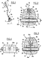
- la figure 2 est une vue de détail en coupe transversale médiane de la partie repérée II sur la figure 1 (coupe faite suivant la ligne II-II de la figure 3),
- la figure 3 est une vue de dessus (complétée par symétrie) dans le sens de la flèche III de la figure 2,
- et, tandis que la figure 2 montre le dispositif de repérage avec son clou non engagé, la figure 4 montre, suivant la même vue en coupe, le même dispositif avec son clou venant perforer la paroi du cathéter.
- FIG. 1 shows in a general schematic view, a possible arrangement of the subcutaneous marking device of the invention on the side of the proximal end of a vascular prosthesis,
- FIG. 2 is a detail view in median cross section of the part marked II in FIG. 1 (section taken along line II-II of FIG. 3),
- FIG. 3 is a top view (completed by symmetry) in the direction of the arrow III in FIG. 2,
- and, while FIG. 2 shows the locating device with its nail not engaged, FIG. 4 shows, in the same sectional view, the same device with its nail coming to perforate the wall of the catheter.
Le dispositif de repérage de l'invention pouvant tout particulièrement être associé à un instrument de filtration sanguine temporaire, on ne décrira ci-après que ce mode de réalisation, les indications contenues dans la présente demande ainsi que les connaissances techniques de l'homme du métier devant lui permettre d'adapter aisément le dispositif pour une utilisation, par exemple, sur un dispositif d'atérectomie, du type de celui de la publication EP 92 402098.5.Since the locating device of the invention can very particularly be associated with a temporary blood filtration instrument, only this embodiment will be described below, the indications contained in the present application as well as the technical knowledge of the person skilled in the art. profession should allow it to easily adapt the device for use, for example, on an aterectomy device, of the type of that of publication EP 92 402098.5.
Sur la figure 1, on voit donc illustrée schématiquement une unité de filtration temporaire 1, tout à fait classique en soi, comprenant un cathéter 3 (ou tout moyen souple, flexible équivalent, tel qu'une tige ou un filament) portant, fixé à lui du côté de son extrémité distale 3a, un filtre sanguin 5, lequel est en l'espèce constitué d'une tête de liaison 7, par exemple sertie à l'extrémité 3a et dans laquelle sont réunies une série de pattes allongées 9 s'étendant essentiellement suivant la direction générale 11 du dispositif. Pour assurer leur rôle de filtration sanguine, ces pattes sont expansibles radialement à l'axe 11, de telle sorte qu'à partir de leur extrémité libre opposée à la tête 7, elles se déploient suivant une corolle sensiblement conique.In FIG. 1, a diagrammatic illustration is thus shown of a
Pour tout renseignement complémentaire relatif au filtre ou au cathéter, on pourra se reporter à la publication américaine US 07/731536 ou encore FR 92 09957 qui sont introduites dans la présente demande par référence.For any additional information relating to the filter or the catheter, reference may be made to the American publication US 07/731536 or also FR 92 09957 which are introduced in the present application by reference.
Concernant le cathéter 3, on notera encore toutefois qu'il est réalisé en une matière biocompatible, telle par exemple qu'une silicone, pour s'adapter en souplesse aux méandres du chemin d'implantation, ou voie d'accès, qu'il doit suivre pour parvenir à l'endroit d'installation prévu dans le vaisseau.Regarding the
Conformément à l'invention, ce cathéter doit en outre être perforable. Du côté de son extrémité proximale 3b, il est par ailleurs équipé d'un dispositif de repérage 13 pouvant extérieurement présenter une forme arrondie, par exemple en olive dépourvue d'angles vifs.According to the invention, this catheter must also be perforable. On the side of its
Comme illustré en particulier sur la figure 2, le dispositif 13 comprend ici une enveloppe extérieure 15 en matériau biocompatible avantageusement souple, ou déformable. A ce sujet, on pourra notamment prévoir de réaliser l'enveloppe en silicone ou équivalent pouvant présenter une dureté comprise entre environ 35 à 40 et 90 à 95 shores A et de préférence, de l'ordre de 50 à 70 shores A.As illustrated in particular in Figure 2, the
Dans la version illustrée, cette enveloppe ou gaine extérieure 15 renferme un clou 17 dont le rôle va être de bloquer en position le dispositif 13 le long du cathéter 3, ainsi qu'un piston 19 de manoeuvre dudit clou et une bague 21 à travers laquelle le clou va passer sensiblement radialement pour perforer le cathéter. Il doit être clair que l'on aurait toutefois pu réduire la section du passage 23 réservé ici au guidage en translation du piston 19, de sorte à adapter la section de ce passage au diamètre du clou 17, dans le but de se passer du piston tout en favorisant le guidage du clou suivant son axe de déplacement 17a. On aurait également pu prévoir de faire ressortir, dans sa position non engagée de la figure 2, le clou 17 hors de l'enveloppe 15, de manière à permettre alors au praticien-opérateur de pouvoir directement venir pousser sur le clou pour l'engager à travers la paroi du cathéter jusqu'à sa position de la figure 4.In the illustrated version, this outer casing or
Quelle que soit la variante choisie, la direction de déplacement du clou est transversale, et de préférence sensiblement perpendiculaire, à l'axe 25a du passage intérieur principal 25 de l'enveloppe dont le diamètre ⌀ sera de préférence très légèrement supérieur au diamètre du cathéter afin de permettre à l'origine d'enfiler aisément l'olive 13 autour de son extrémité proximale 3b.Whatever the variant chosen, the direction of movement of the nail is transverse, and preferably substantially perpendicular, to the
Dans la réalisation illustrée, le clou 17 s'étend exclusivement à l'intérieur du passage secondaire transversal 23, d'axe 17a, de l'enveloppe, en étant lié (par exemple engagé à force et/ou collé), du côté opposé à sa pointe de perforation 17b, au piston 19 qui est donc adapté pour glisser également dans le passage 23. A ce sujet, on remarquera que le piston pourra présenter, pour faciliter sa manoeuvre, une forme de cylindre en "I" suivant une coupe faite dans un plan contenant l'axe 17a (plan de coupe de la figure 2).In the illustrated embodiment, the
Notamment pour éviter toute manoeuvre malencontreuse du piston et/ou du clou, le passage 23 qui peut communiquer exclusivement, en 23a, avec l'extérieur pourra présenter localement une zone 24 de retenue du piston en position non engagée du clou (position de la figure 2).In particular to avoid any inadvertent operation of the piston and / or the nail, the
Si la bague 21 n'est pas réalisée en un matériau perforable, elle présentera, dans le prolongement du passage 23, une ouverture radiale traversant la bague de préférence de part en part, le diamètre de cette ouverture pouvant n'être que très légèrement supérieur à celui du clou pour la partie 31a dans laquelle le clou est en l'espèce en permanence engagé, tandis que du côté diamétralement opposé 31b, le diamètre de l'ouverture peut être plus large.If the
Le positionnement optimal de l'enveloppe 15 peut s'effectuer comme suit : après avoir enfilé correctement l'enveloppe autour du cathéter, le praticien vient appuyer avec ses doigts sur la partie de celle-ci qui entoure le piston 19, lequel est alors dans sa position "arrière" de la figure 2 (clou à proximité immédiate de la paroi 3c du cathéter). Le praticien doit appuyer suffisamment pour le dégager le piston de sa zone de retenue 24 dont notamment l'épaulement 26 retient la semelle arrière 20 du piston. Dans la mesure où l'on aura de préférence choisi la matière de l'enveloppe pour que celle-ci soit déformable, l'effort exercé sur elle va avoir tendance à déformer la zone d'entourage du piston, jusqu'à le libérer pour que, sous cette poussée, il coulisse dans le sens de la flèche 33 de la figure 2, ses semelles 20, 22 assurant son guidage. Entraîné par le piston, le clou perfore alors la paroi 3c du cathéter, jusqu'à ressortir du côté diamétralement opposé dans l'orifice 31b. Le piston est alors en position "avant" de la figure 4, en butée contre la bague 21.The optimal positioning of the
On notera que si la matière de l'enveloppe a été choisie translucide, ou transparente, le praticien pourra s'assurer du bon engagement du clou à la fois par la sensation tactile ressentie et par une vérification visuelle. Quoi qu'il en soit, la perforation du cathéter par le clou aura fixé longitudinalement la position de l'enveloppe.It will be noted that if the material of the envelope has been chosen translucent, or transparent, the practitioner will be able to make sure of the good engagement of the nail both by the tactile sensation felt and by a visual verification. Either way, the puncture of the catheter by the nail will have fixed the position of the envelope longitudinally.
Pour éviter d'affaiblir le cathéter 3 (sans donc l'obturer), il pourrait être avantageux de prévoir un diamètre de clou 17 inférieur au diamètre intérieur du cathéter. Un rapport de 3 à 4 peut être approprié.To avoid weakening the catheter 3 (without therefore closing it), it could be advantageous to provide a
Si la matière de l'enveloppe 15 est réellement souple, le praticien pourra éventuellement, par une nouvelle pression extérieure sur cette enveloppe, entraîner le piston à contresens (flèche 37 de la figure 4) jusqu'à ce qu'il retourne avec le clou à sa suite dans sa position arrière de la figure 2, permettant ainsi de repositionner si nécessaire le dispositif 13 en un autre endroit le long du cathéter. Il doit toutefois être clair que rien n'oblige à ce que cette possibilité de retour en arrière du piston soit permise.If the material of the
Claims (10)
caractérisé en ce que lesdits moyens de blocage comprennent un clou (17) disposé suivant une direction transversale (17a) à l'axe (25a) du passage principal (25) de l'enveloppe dans laquelle ledit clou est monté glissant suivant cette dite direction transversale pour perforer le cathéter.
characterized in that said locking means comprise a nail (17) arranged in a transverse direction (17a) to the axis (25a) of the main passage (25) of the envelope in which said nail is mounted sliding in this said direction transverse to perforate the catheter.
Applications Claiming Priority (2)
| Application Number | Priority Date | Filing Date | Title |
|---|---|---|---|
| FR9313668 | 1993-11-16 | ||
| FR9313668A FR2712485B1 (en) | 1993-11-16 | 1993-11-16 | Device for subcutaneous identification of a medical prosthesis and corresponding prosthesis. |
Publications (1)
| Publication Number | Publication Date |
|---|---|
| EP0653193A1 true EP0653193A1 (en) | 1995-05-17 |
Family
ID=9452902
Family Applications (1)
| Application Number | Title | Priority Date | Filing Date |
|---|---|---|---|
| EP94402537A Withdrawn EP0653193A1 (en) | 1993-11-16 | 1994-11-09 | Subcutaneous locating device and related medical prosthesis |
Country Status (3)
| Country | Link |
|---|---|
| US (1) | US5695470A (en) |
| EP (1) | EP0653193A1 (en) |
| FR (1) | FR2712485B1 (en) |
Families Citing this family (36)
| Publication number | Priority date | Publication date | Assignee | Title |
|---|---|---|---|---|
| US5824055A (en) * | 1997-03-25 | 1998-10-20 | Endotex Interventional Systems, Inc. | Stent graft delivery system and methods of use |
| US6623462B2 (en) | 2001-05-11 | 2003-09-23 | Harmac Medical Products, Inc. | Needle safety guard |
| US6824530B2 (en) | 2001-05-11 | 2004-11-30 | Harmac Medical Products, Inc. | Combination needle assembly and needle safety guard |
| US8340779B2 (en) | 2003-08-29 | 2012-12-25 | Medtronic, Inc. | Percutaneous flat lead introducer |
| WO2006135753A1 (en) * | 2005-06-09 | 2006-12-21 | Medtronic, Inc. | Introducer for therapy delivery elements |
| US7699809B2 (en) | 2006-12-14 | 2010-04-20 | Urmey William F | Catheter positioning system |
| WO2010011995A1 (en) * | 2008-07-25 | 2010-01-28 | Roger Alan Mason | Vascular access device |
| CA3192660A1 (en) | 2011-05-18 | 2012-11-22 | Solo-Dex, Inc. | Continuous anesthesia nerve conduction apparatus, system and method |
| US8986283B2 (en) | 2011-05-18 | 2015-03-24 | Solo-Dex, Llc | Continuous anesthesia nerve conduction apparatus, system and method thereof |
| US9320872B2 (en) | 2011-10-14 | 2016-04-26 | William F. Urmey | Catheter positioning system |
| US20140236213A1 (en) * | 2013-02-15 | 2014-08-21 | BiO2 Medical, Inc. | Temporary filter retrieval apparatus and method |
| US10912898B1 (en) | 2014-02-03 | 2021-02-09 | Medical Device Engineering Llc | Tamper evident cap for medical fitting |
| US11097071B1 (en) | 2016-12-14 | 2021-08-24 | International Medical Industries Inc. | Tamper evident assembly |
| US10953162B1 (en) | 2016-12-28 | 2021-03-23 | Timothy Brandon Hunt | Tamper evident closure assembly |
| US10758684B1 (en) | 2017-03-03 | 2020-09-01 | Jonathan J. Vitello | Tamper evident assembly |
| US11040149B1 (en) | 2017-03-30 | 2021-06-22 | International Medical Industries | Tamper evident closure assembly for a medical device |
| US10888672B1 (en) | 2017-04-06 | 2021-01-12 | International Medical Industries, Inc. | Tamper evident closure assembly for a medical device |
| US10933202B1 (en) | 2017-05-19 | 2021-03-02 | International Medical Industries Inc. | Indicator member of low strength resistance for a tamper evident closure |
| US10898659B1 (en) | 2017-05-19 | 2021-01-26 | International Medical Industries Inc. | System for handling and dispensing a plurality of products |
| US11541180B1 (en) | 2017-12-21 | 2023-01-03 | Patrick Vitello | Closure assembly having a snap-fit construction |
| US11278681B1 (en) | 2018-02-20 | 2022-03-22 | Robert Banik | Tamper evident adaptor closure |
| US11413406B1 (en) | 2018-03-05 | 2022-08-16 | Jonathan J. Vitello | Tamper evident assembly |
| US11793987B1 (en) | 2018-07-02 | 2023-10-24 | Patrick Vitello | Flex tec closure assembly for a medical dispenser |
| US11779520B1 (en) | 2018-07-02 | 2023-10-10 | Patrick Vitello | Closure for a medical dispenser including a one-piece tip cap |
| US11857751B1 (en) | 2018-07-02 | 2024-01-02 | International Medical Industries Inc. | Assembly for a medical connector |
| US11690994B1 (en) | 2018-07-13 | 2023-07-04 | Robert Banik | Modular medical connector |
| US11426328B1 (en) | 2018-08-31 | 2022-08-30 | Alexander Ollmann | Closure for a medical container |
| USD948713S1 (en) | 2019-09-03 | 2022-04-12 | International Medical Industries, Inc. | Asymmetrical self righting tip cap |
| US11471610B1 (en) | 2018-10-18 | 2022-10-18 | Robert Banik | Asymmetrical closure for a medical device |
| USD903865S1 (en) | 2018-11-19 | 2020-12-01 | International Medical Industries, Inc. | Self-righting tip cap |
| US11911339B1 (en) | 2019-08-15 | 2024-02-27 | Peter Lehel | Universal additive port cap |
| US11697527B1 (en) | 2019-09-11 | 2023-07-11 | Logan Hendren | Tamper evident closure assembly |
| US11357588B1 (en) | 2019-11-25 | 2022-06-14 | Patrick Vitello | Needle packaging and disposal assembly |
| US11904149B1 (en) | 2020-02-18 | 2024-02-20 | Jonathan Vitello | Oral tamper evident closure with retained indicator |
| US11523970B1 (en) | 2020-08-28 | 2022-12-13 | Jonathan Vitello | Tamper evident shield |
| US11872187B1 (en) | 2020-12-28 | 2024-01-16 | Jonathan Vitello | Tamper evident seal for a vial cover |
Citations (4)
| Publication number | Priority date | Publication date | Assignee | Title |
|---|---|---|---|---|
| US4735615A (en) * | 1987-02-24 | 1988-04-05 | Uddo Jr Joseph F | Cholangioclamp |
| EP0472334A1 (en) * | 1990-08-14 | 1992-02-26 | Cook Incorporated | Apparatus for filtering blood in a blood vessel of a patient |
| EP0521222A1 (en) * | 1990-01-19 | 1993-01-07 | Pierre Gory | Device for temporary implanting a blood filter into a vein of the human body |
| EP0564321A2 (en) * | 1992-04-01 | 1993-10-06 | B. Braun Celsa | Drug injecting device |
Family Cites Families (11)
| Publication number | Priority date | Publication date | Assignee | Title |
|---|---|---|---|---|
| US2625934A (en) * | 1951-04-20 | 1953-01-20 | Thomas W Halliday | Surgical wire feeding device |
| US2670730A (en) * | 1952-11-14 | 1954-03-02 | George O A Kellogg | Surgical instrument for operative and diagnostic purposes |
| US3017887A (en) * | 1960-01-19 | 1962-01-23 | William T Heyer | Stereotaxy device |
| US5195526A (en) * | 1988-03-11 | 1993-03-23 | Michelson Gary K | Spinal marker needle |
| US5009644A (en) * | 1989-07-25 | 1991-04-23 | Medtronic, Inc. | Needle placement verifier |
| US5171228A (en) * | 1989-07-25 | 1992-12-15 | Medtronic, Inc. | Apparatus for medical instrument placement verification |
| US5167629A (en) * | 1990-12-06 | 1992-12-01 | Vertenstein Mathieu J | Vein locator |
| US5360407A (en) * | 1991-08-29 | 1994-11-01 | C. R. Bard, Inc. | Implantable dual access port with tactile ridge for position sensing |
| DE4138240A1 (en) * | 1991-11-21 | 1993-05-27 | Peter C Dr Krueger | MEDICAL INSTRUMENT |
| FR2689388B1 (en) * | 1992-04-07 | 1999-07-16 | Celsa Lg | PERFECTIONALLY RESORBABLE BLOOD FILTER. |
| US5460612A (en) * | 1994-09-19 | 1995-10-24 | Madore; Linda E. | Vascular access port stabilizing tool |
-
1993
- 1993-11-16 FR FR9313668A patent/FR2712485B1/en not_active Expired - Fee Related
-
1994
- 1994-11-09 EP EP94402537A patent/EP0653193A1/en not_active Withdrawn
- 1994-11-15 US US08/340,399 patent/US5695470A/en not_active Expired - Lifetime
Patent Citations (4)
| Publication number | Priority date | Publication date | Assignee | Title |
|---|---|---|---|---|
| US4735615A (en) * | 1987-02-24 | 1988-04-05 | Uddo Jr Joseph F | Cholangioclamp |
| EP0521222A1 (en) * | 1990-01-19 | 1993-01-07 | Pierre Gory | Device for temporary implanting a blood filter into a vein of the human body |
| EP0472334A1 (en) * | 1990-08-14 | 1992-02-26 | Cook Incorporated | Apparatus for filtering blood in a blood vessel of a patient |
| EP0564321A2 (en) * | 1992-04-01 | 1993-10-06 | B. Braun Celsa | Drug injecting device |
Also Published As
| Publication number | Publication date |
|---|---|
| FR2712485B1 (en) | 1995-12-22 |
| FR2712485A1 (en) | 1995-05-24 |
| US5695470A (en) | 1997-12-09 |
Similar Documents
| Publication | Publication Date | Title |
|---|---|---|
| EP0653193A1 (en) | Subcutaneous locating device and related medical prosthesis | |
| EP0605351B1 (en) | Instrument for the removal of a length of vein | |
| EP1237501B1 (en) | Prosthesis for controlling the direction of flow in a duct of a living organism | |
| EP1210913A1 (en) | Device for protecting a piercing tool | |
| EP0348295A1 (en) | Medical filter | |
| EP1336398A1 (en) | Applicator for tampons | |
| FR2768917A1 (en) | Reusable handle for disposable medical instrument | |
| FR2481103A1 (en) | MEDICAL BISTOURI FOR COLLECTING A BLOOD DROP AND METHOD FOR MANUFACTURING THE SAME | |
| EP0826340A2 (en) | Support for surgical staple of elastic, superelastic or shape memory type | |
| FR2772592A1 (en) | ASSEMBLY FOR THE PLACEMENT OF AN IMPLANT IN AN INTERNAL CONDUIT OF A BODY | |
| EP1443871A1 (en) | Mini sub-urethral/cervical support | |
| FR2910269A1 (en) | Heart valve e.g. heart mitral valve, processing equipment, has implant deployed from catheter while being moved and driven by rotation, where rotation allows implant to penetrate into tissue of ring while implant guides along ring | |
| FR2710833A1 (en) | Device for implanting a medical prosthesis in a conduit of a human or animal body and method of centering such a device. | |
| EP0968682B1 (en) | Blood sampling device for a vacuum evacuated tube | |
| EP1458315A1 (en) | Medical device for explantation | |
| EP3361962A1 (en) | Inflatable balloon for medical use | |
| WO2018024617A1 (en) | Deployable implant | |
| FR3011175A1 (en) | DEVICE FOR INJECTING AN INTRAOCULAR CATARACT TREATMENT LENS AND CORRESPONDING CATARACT TREATMENT ASSEMBLY | |
| FR3018195A1 (en) | SURGICAL INTRAVASCULAR GUITAR RECAPTURE INSTRUMENT | |
| FR2855746A1 (en) | Intraocular lens capsule part cutting device for cataract surgery, has circular wire with cutting edge and rolled in guide tube during its insertion into eye and unrolled to be applied on capsule to repeatedly perform cutting operation | |
| FR2979229A1 (en) | ENDOPROTHESIS FENESTRATION DEVICE | |
| FR2860705A1 (en) | Delivery apparatus for prosthesis such as stent has two-position hook on end of pusher wire to release stent after positioning with catheter | |
| FR2774894A1 (en) | FLEXIBLE BIOCOMPATIBLE ROD FOR INSTALLATION IN AN ANATOMICAL DUCT AND DEVICE EQUIPPED WITH SUCH A ROD | |
| FR2979228A1 (en) | UNIVERSAL AORTIC ENDOPROTHESIS | |
| EP0787467A1 (en) | Protective device for bone pin |
Legal Events
| Date | Code | Title | Description |
|---|---|---|---|
| PUAI | Public reference made under article 153(3) epc to a published international application that has entered the european phase |
Free format text: ORIGINAL CODE: 0009012 |
|
| AK | Designated contracting states |
Kind code of ref document: A1 Designated state(s): AT BE DE ES GB IT |
|
| 17P | Request for examination filed |
Effective date: 19951016 |
|
| 17Q | First examination report despatched |
Effective date: 19980116 |
|
| STAA | Information on the status of an ep patent application or granted ep patent |
Free format text: STATUS: THE APPLICATION IS DEEMED TO BE WITHDRAWN |
|
| 18D | Application deemed to be withdrawn |
Effective date: 19980527 |