EP0653858B1 - OFDM Synchronization demodulation circuit - Google Patents
OFDM Synchronization demodulation circuit Download PDFInfo
- Publication number
- EP0653858B1 EP0653858B1 EP94308433A EP94308433A EP0653858B1 EP 0653858 B1 EP0653858 B1 EP 0653858B1 EP 94308433 A EP94308433 A EP 94308433A EP 94308433 A EP94308433 A EP 94308433A EP 0653858 B1 EP0653858 B1 EP 0653858B1
- Authority
- EP
- European Patent Office
- Prior art keywords
- signal
- orthogonal
- output
- detection signal
- axis detection
- Prior art date
- Legal status (The legal status is an assumption and is not a legal conclusion. Google has not performed a legal analysis and makes no representation as to the accuracy of the status listed.)
- Expired - Lifetime
Links
Images


Classifications
-
- H—ELECTRICITY
- H04—ELECTRIC COMMUNICATION TECHNIQUE
- H04L—TRANSMISSION OF DIGITAL INFORMATION, e.g. TELEGRAPHIC COMMUNICATION
- H04L27/00—Modulated-carrier systems
- H04L27/26—Systems using multi-frequency codes
- H04L27/2601—Multicarrier modulation systems
- H04L27/2647—Arrangements specific to the receiver only
- H04L27/2655—Synchronisation arrangements
- H04L27/2662—Symbol synchronisation
- H04L27/2665—Fine synchronisation, e.g. by positioning the FFT window
-
- H—ELECTRICITY
- H04—ELECTRIC COMMUNICATION TECHNIQUE
- H04L—TRANSMISSION OF DIGITAL INFORMATION, e.g. TELEGRAPHIC COMMUNICATION
- H04L27/00—Modulated-carrier systems
- H04L27/26—Systems using multi-frequency codes
- H04L27/2601—Multicarrier modulation systems
- H04L27/2647—Arrangements specific to the receiver only
- H04L27/2655—Synchronisation arrangements
- H04L27/2657—Carrier synchronisation
-
- H—ELECTRICITY
- H04—ELECTRIC COMMUNICATION TECHNIQUE
- H04L—TRANSMISSION OF DIGITAL INFORMATION, e.g. TELEGRAPHIC COMMUNICATION
- H04L27/00—Modulated-carrier systems
- H04L27/26—Systems using multi-frequency codes
- H04L27/2601—Multicarrier modulation systems
- H04L27/2647—Arrangements specific to the receiver only
- H04L27/2655—Synchronisation arrangements
- H04L27/2662—Symbol synchronisation
Definitions
- the present invention relates to an OFDM synchronization demodulation circuit, and more particularly to, an OFDM synchronization demodulation circuit which obtains symbol synchronization and carrier synchronization from information signals.
- OFDM orthogonal frequency division multiplex
- sub-carriers transmitted digital data in multiple carriers (hereinafter referred to as sub-carriers) which are mutually orthogonal and to modulate each of them.
- the OFDM has such merits that frequency utilization factor is high and it hardly supplies disturbance to others in addition to a feature that it is hardly subject to the effect of multiple path interference.
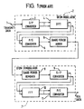
- FIGURE 1 is a block diagram showing a conventional OFDM modulator/demodulator.
- Transmitted data which is input through an input terminal 1 is, for instance, a QPSK modulated or QAM modulated signal.
- the transmitted data is supplied to a serial/parallel converter 3 of an OFDM modulator 2, where the data is converted into low speed parallel data comprising multiple symbols.
- the number of symbols per parallel data coincides with the number of sub-carriers.
- An inverse fast Fourier transform (hereinafter referred to as IFFT) circuit 4 modulates parallel several hundred through several thousand mutually orthogonal sub-carriers by parallel data.
- the number of sub-carriers is set according to the number of using points of the IFFT circuit 4.
- the transmitted data which has been OFDM modulated by the IFFT circuit 4 is supplied to a parallel/serial converter 5, where it is converted into serial data and supplied to a guard period adding circuit 6.
- the guard period adding circuit 6 adds a guard period to the serial data in order to prevent the multiple path interference and outputs the data to a transmission line (not shown).
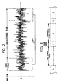
- FIGURE 2 is a typical waveform diagram showing the transmitted data added with a guard period.
- a guard period adding circuit 8 provides a guard period which is a latter half of the available symbol period copied cyclically, as shown in FIGURE 2. If the delay time of multiple path interference is within the guard period, it is possible to prevent inter-symbol interference by delayed adjacent symbols by demodulating the available symbol period signal only at the time of demodulation.
- the OFDM demodulation circuit 7 data received from a transmission line (not shown) is supplied to a guard period removing circuit 8.
- the guard period removing circuit 8 extracts signals in the available symbol period from the received data and supplies them to a serial/parallel converter 9.
- the serial/parallel converter 9 converts serial data into parallel data for every sub-carrier and outputs them to a fast Fourier transform (hereinafter referred to a FFT) circuit 10.
- the FFT circuit 10 demodulates sub-carriers through the FFT operation.
- the demodulated signal output from the FFT circuit 10 is converted into serial data by a parallel/serial converter 11 and is output as received data.
- the FFT circuit 10 executes the accurate demodulation, it is necessary to obtain a timing synchronization (hereinafter referred to as the symbol synchronization) of the available symbol period. Further, as transmission data is transmitted after orthogonally modulated, it is also necessary to obtain a carrier synchronization at a receiver section for the proper orthogonal demodulation.
- the OFDM modulated wave is a waveform similar to random noise, as shown in FIGURE 2, it is difficult to obtain the symbol synchronization and the carrier synchronization based on the OFDM modulated wave.
- FIGURE 3 is an explanatory diagram for explaining such a conventional symbol synchronizing method.
- a guard period has been added to the transmitted data. That is, as shown in FIGURE 3, transmitted data of one symbol has the available symbol period S and the guard period G. Further, a non-signal period (hereinafter referred to as the null symbol period) for symbol synchronization is added for every several tens of symbol periods.
- the null symbol period a non-signal period for symbol synchronization is added for every several tens of symbol periods.
- FIGURE 4 is a graph for explaining a carrier synchronization method of another conventional OFDM synchronization demodulation circuit, which has been described in "Summary of OFDM Experiments done by the ARTC".
- frequency is plotted on the X-axis and amplitude of a spectrum plotted on the Y-axis, and the central frequency band indicates sub-carriers modulated by transmitted data.
- Sub-carriers at both sides of the frequency band are not modulated and used as pilot carriers 15 and 16.
- the carrier synchronization is attained by detecting the pilot carriers.
- null symbols may be disturbed and erroneously detected. So, there was such a problem that the normal demodulating operation was not carried out for a long time until next null symbol was detected in this case. If null symbols are sent frequently to solve the problem, transmission efficiency drops. Further, in a method for executing the carrier synchronization using pilot carriers, the carrier synchronization cannot be attained if pilot carriers are disturbed.
- WO92/10043 and EP0453,203 are both examples of OFDM systems which require the use of pilot signals for synchronizing an OFDM demodulator.
- an object of the present invention to provide an OFDM synchronization demodulation circuit which is capable of executing the symbol synchronization and the carrier synchronization from transmitted information signals only.
- an OFDM synchronization demodulation circuit includes a receiving circuit for receiving an orthogonal modulated wave of an orthogonal frequency division multiplex (OFDM) modulated signal having an available symbol period and a guard period in waveform which coincides with a part of the available symbol period, an orthogonal axes demodulation circuit for demodulating an in-phase axis detection signal and an orthogonal axis detection signal through orthogonal detection for the OFDM modulated wave from the receiving circuit, a first delay circuit for delaying the in-phase axis detection signal by the available symbol period, a second delay circuit for delaying the orthogonal axis detection signal by the available symbol period, a correlation calculation circuit for calculating coefficients of the correlations of the in-phase axis detection signal and the orthogonal axis detection signal from the orthogonal demodulation circuit with the output of the first or the second delay circuits, a guard timing detection circuit for detecting a timing of the guard period in the de
- an OFDM synchronization demodulation circuit includes a receiving circuit for receiving an orthogonal modulated wave of an orthogonal frequency division multiplex (OFDM) modulated signal having an available symbol period and a guard period in waveform which coincides with a part of the available symbol period, an orthogonal axes demodulation circuit for demodulating en in-phase axis detection signal and an orthogonal axis detection signal through orthogonal detection for the OFDM modulated wave from the receiving means, a first delay circuit for delaying the in-phase axis detection signal by the available symbol period, a second delay circuit for delaying the orthogonal axle detection signal by the available symbol period, a correlation calculation circuit for calculating coefficients of the correlations of the in-phase axis detection signal and the orthogonal axis detection signal from the orthogonal demodulation circuit with the output of the first or the second delay circuit, an OFDM signal demodulation circuit for demodulating the OFDM modulated signal by extracting the available symbol period signal only
- OFDM orthogonal frequency division
- the guard period of the orthogonal frequency division multiplex modulated signal is identical to a part of the available symbol period signal
- the in-phase axis detection signal and the orthogonal axis detection signal from the orthogonal demodulating means are correlative with the outputs of the first and the second delaying means, respectively, if a detected frequency is proper.
- the in-phase axis detection signal and the orthogonal axis detection signal are correlative with the outputs of the second and the first delaying means. respectively.
- the guard timing detection means detects the guard period timing based on the result of correlation and the demodulating means performs the demodulation by extracting the symbol period signal based on the timing signal.
- the frequency deviation detection means detects a detection frequency deviation of the orthogonal demodulating means based on the result of correlation. The carrier synchronization is attained by controlling detection frequency using the detection frequency deviation.
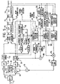
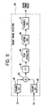
- FIGURE 5 is a block diagram showing the embodiment of the OFDM synchronization demodulation circuit.
- An OFDM modulated signal which was received by a tuner (not shown) and converted into intermediate frequency band signal (hereinafter referred to as IF signal) is input to an input terminal 31.
- the OFDM modulated signal input to the input terminal 31 is, for instance, a QAM signal which was OFDM modulated and orthogonal modulated by specific carriers at a transmitter section and then transmitted. Further, the QAM signal is capable of expressing symbols by an I-data corresponding to the real part of a complex form signal and a Q-data corresponding to the imaginary part of the complex form signal.
- the transmitted OFDM modulated signal does not have the null symbol period, as shown in FIGURE 3, and also it does not have the pilot carrier, as shown in FIGURE 4.
- the IF signal is supplied to a band-pass filter (hereinafter referred to as BPF) 32, which in turn removes noise outside the passing band and outputs the IF signal to multipliers 33, 34.
- BPF band-pass filter
- Oscillation output frequency (restored carrier) of a local oscillator 35 is controlled by a control signal from a D/A converter 105 which will be described later and is output to the multiplier 33 and also, to the multiplier 34 via a phase shifter 36.
- the phase shifter 36 obtains Q-axis local oscillation output by shifting the local oscillation output (I-axis local oscillation output) by 90° .
- the multipliers 33 and 34 perform the orthogonal detection by multiplying the I-axis or Q-axis local oscillation output by the IF signal.
- the in-phase axis detection output (I-signal) from the multiplier 33 is applied to an A/D converter 38 via a low-pass filter (hereinafter referred to as LPF) 37.
- LPF low-pass filter
- the orthogonal axis detection output (Q-signal) from the multiplier 34 is applied to an A/D converter 40 via an LPF 39.
- LPFs 37, 39 remove harmonic components of the I-signal or Q-signal, respectively.
- the A/D converters 38, 40 are supplied with operational clocks from a local oscillator 109, which will be described later, and converting input signal into digital signal, output it to a guard period removing circuit 41 comprising an OFDM demodulator section 45.
- the OFDM demodulator section 45 has a similar structure as an OFDM demodulator 7, as shown in FIGURE 1, and is comprised of a guard period removing circuit 41, a serial/parallel conversion circuit 42, an FFT circuit 43 and a parallel/serial conversion circuit 44.
- the guard period removing circuit 41 is supplied with a guard timing signal from a guard timing detection circuit 55, which will be described later, removing the guard period of OFDM modulated signals (I-signal, Q-signal) and extracting an available symbol period signal, outputs the OFDM modulated signal to the serial/parallel conversion circuit 42.
- the serial/parallel conversion circuit 42 converts serial data into parallel data and outputs the parallel data to the FFT circuit 43.
- the FFT circuit regarding the I-signal and the Q-signal as the real part and the imaginary part of the complex form signal, respectively, performs the FFT process.
- the FFT process the synchronization demodulation of each sub-carrier is executed. That is, the real part and the imaginary part of the complex form signal output which has been PPT processed by the FFT circuit 43 become the I-data and the Q-data which are demodulated symbols of each sub-carrier, respectively.
- These I-data and Q-data are supplied to the parallel/serial conversion circuit 44, which in turn outputs these data after converting them into serial data.
- FIGURES 6(a) through 6(e) are timing charts for explaining the symbol synchronization detection block 50, as shown in FIGURE 5.
- FIGURE 6(a) shows the output of the A/D converter 38.
- FIGURE 6(b) shows the output of a delay circuit 51.
- FIGURE 6(c) shows the output of a correlator 53.
- FIGURE 6(d) shows the guard timing.
- FIGURE 6(e) shows the guard removing gate pulse.
- the symbol synchronization detection block 50 is comprised of the delay circuits 51, 52, the correlators 53, 54 and the guard timing detection circuit 55.
- the delay circuits 51, 52 output the I-signal and the Q-signal to the correlators 53, 54 by delaying them by an available symbol period ts.
- the I-signal from the A/D converter 38 is also input to the correlators 53, 54.
- the correlator 53 obtains a correlation coefficient of the I-signal with the delayed I-signal at a gate width of the guard period and the correlator 54 obtains a correlation coefficient of the I-signal with the delayed Q-signal.
- the OFDM modulated signal is added with the guard periods G1, G2, ... at the leading section of the available symbol periods S1, S2, ... (See FIGURE 6(a)).
- the guard periods G1, G2, ... are copied terminal periods G1', G2', ... of the available symbol period S1, S2, ... Therefore, if the I-signal from the A/D converter 38 is delayed by the available symbol period, the timings of the guard periods G1, G2, ... coincide with the timings of the terminating periods G1', G2', ...
- the guard period signal is a copied terminal end signal, during the period, the I-signal and its delayed signal are highly correlated.
- a correlation coefficient from the correlator 53 is supplied to the guard timing detection circuit 55.
- the guard timing detection circuit 55 detects the peak timing, as shown in FIGURE 6(c). and outputs the peak timing to the guard period removing circuit 41 as the guard timing signal (FIGURE 6(d)).
- the guard period removing circuit 41 generates a guard removing gate pulse (FIGURE 6(e)) based on the guard timing signal and removes the guard period based on the gate pulse.
- FIGURES 7(a), 7(b) through 10 are graphs showing correlation coefficients obtained from the correlators 53, 54 through the simulation with times plotted at the X-axis and normalized correlation coefficient at the Y-axis.
- FIGURES 7(a), 8(a) and 9(a) show the correlation coefficient SI between the I-signal and its delayed signal
- FIGURES 7(b), 8(b) and 9(b) show the correlation coefficient SQ between the I-signal and the delayed signal of Q-signal.
- FIGURES 7(a) and 7(b) show an example in a case where the carrier synchronization is attained, that is, frequency deviation ⁇ f between the local oscillation frequency (restored carrier frequency) from the local oscillator 35 and carrier frequency is zero (0).
- the correlation coefficient SI reaches the peak at the end timing of the terminating period G1', G2', ... as shown in FIGURE 7(a).
- the I-signal and the Q-signal are signals of which phases are deviated by 90° on the complex plane and haven't been correlated with each other and therefore, the correlation coefficient SQ between the I-signal and the delayed signal of the Q-signal becomes a value near zero (0), as shown in FIGURE 7(b).
- FIGURES 8(a) and 8(b) show an example in a case where the carrier frequency deviation ⁇ f is fs/8 (fs is a frequency difference between adjacent sub-carriers).
- the phase of signal G' advances by 45° more than signal G. Therefore, the peak value of the correlation coefficient will become smaller than that when the carrier synchronization is attained, as shown in FIGURE 8(a).
- the correlation is generated between the I-signal and the delayed signal of the Q-signal, and the correlation coefficient SQ drops to a lower level from the terminating period and reaches the negative peak at the end timing of the terminating period, as shown in FIGURE 8(b).
- FIGURES 9(a) and 9(b) show an example of a case where a carrier frequency deviation ⁇ f is fs/4.
- the phase of signal G' advances 90° more than signal G. Therefore, the correlation coefficient SI will become a value near zero (0), as shown in FIGURE 9(a), and the efficient of correlation SQ reaches the negative peak at the end timing of the terminating period, as shown in FIGURE 9(b).
- the end timing of the terminating period can be seen from the correlation coefficients SI, SQ even when no carrier synchronization was attained. For this reason, the correlator 54 obtains the correlation coefficient SQ of the I-signal with the delayed signal of the Q-signal and outputs it to the guard timing detection circuit 55.
- FIGURE 11 is a block diagram showing the definite structure of the guard timing detection circuit 55, as shown in FIGURE 5.
- the correlation coefficients SI, SQ are supplied to square circuits 81, 82, respectively.
- the square circuits 81, 82 square the correlation coefficients SI, SQ, respectively and output the results to an adder 83.
- the adder 83 adds up the outputs of the square circuits 81, 82 and supplies the result to an LPF 84.
- FIGURE 10 is graph showing the arithmetic operating result and shows an example of a case where no carrier synchronization was attained.
- the LPF 84 smoothes the output of the adder 83 and supplies it to a peak extraction circuit 85.
- the peak extraction circuit 85 extracts signal in amplitude above a specific level and outputs to a judging circuit 86.
- the judging circuit 86 detects a peak position from the result of extraction of the peak extraction circuit and outputs a timing signal at the peak position.
- the timing signal is supplied to a flywheel circuit 87.
- the flywheel circuit 87 is reset by the timing signal from the judging circuit 86 and outputs a guard timing signal of a fixed cycle based on the timing signal cycle.
- FIGURE 12 is a block diagram showing another example of the guard timing detection circuit.
- the component elements identical to those, as shown in FIGURE 11, are assigned with the same reference numerals and the explanation will be omitted.
- absolute value circuits 89, 90 have been adopted instead of the square circuits 81, 82. It is apparent that the peak position is detectable from the result of adding absolute values of the correlation coefficients SI, SQ and the guard timing signal can be obtained even when the guard timing detection circuit 88 in FIGURE 12 [8] is used.
- the correlation coefficients SI, SQ from the correlators 53, 54 are also supplied to a carrier synchronization detection block 60.
- the carrier synchronization detection block 60 is comprised of a carrier frequency deviation detection circuit 61 and a carrier frequency control circuit 62.
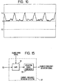
- FIGURE 13 is a block diagram showing the definite structure of the carrier frequency deviation detection circuit, as shown in FIGURE 5. Further, FIGURES 14(a), 14(b) and 14(c) are graphs for explaining the carrier frequency deviation detection circuit, as shown in FIGURE 13.
- FIGURE 14(a), 14(b) and 14(c) show the relation of the correlation coefficients SI and SQ at the guard timing by plotting carrier frequency deviation ⁇ f at the X-axis and normalized correlation coefficients SI and SQ, respectively or an arc tangent SQ/SI at the Y-axis.
- the correlation coefficients SI and SQ are input to gates 91 and 92 of the carrier frequency deviation detection circuit 61, and the gates 91 ad 92 output the correlation coefficients SI and SQ to a calculation unit 93 at the timing of the guard timing signal.
- the calculation unit 93 obtains an arc tangent of the correlation coefficient SQ/SI and outputs it to a frequency deviation signal generation circuit 94.
- the correlation coefficients SI, SQ will change according to the carrier frequency deviation ⁇ f as described above. However, the change in the correlation coefficients SI, SQ at the guard timing has regularity, as shown in FIGURES 14(a) and 14(b), and becomes a function of the carrier frequency deviation ⁇ f.
- the frequency deviation signal generating circuit 94 uses a signal, as shown in FIGURE 14(c), as the carrier frequency deviation signal in order to control carrier frequency.
- the carrier frequency deviation signal is supplied to a carrier frequency control circuit 62.
- FIGURE 15 is a block diagram showing another example of the carrier frequency deviation detection circuit.
- the correlation coefficient SQ is input to a gate 98 of a carrier frequency deviation detection circuit 97.
- the gate 98 outputs the correlation coefficient SQ to a frequency deviation signal generation circuit 99 at the timing of guard timing signal.
- the correlation coefficient SQ at the guard timing will become zero (0) if the carrier frequency deviation ⁇ f is integer multiple of fs. Therefore, the same effect, as shown in FIGURE 13, can be obtained when the frequency deviation signal generation circuit 99 uses a signal, as shown in FIGURE 14(b), as a carrier frequency deviation signal.
- the output of the parallel/serial conversion circuit 44 is supplied to a carrier frequency deviation detection circuit 101 and a carrier phase deviation detection circuit 102.
- the carrier frequency deviation detection circuit 101 detects frequency deviation of restored carrier by analyzing frequency of each sub-carrier power. In general, maximum and minimum frequency sub-carriers out of OFDM modulated signal sub-carriers are made as guard bands and therefore, are not used (zero carrier).
- the output of the carrier frequency deviation detection circuit 101 is supplied to the carrier frequency control circuit 62.
- the carrier frequency control circuit 62 generates a control signal for controlling oscillation frequency of the local oscillator 35 from the output of the carrier frequency deviation detection circuit 101 and a carrier frequency deviation signal from the carrier frequency deviation detection circuit 61 and outputs the generated control signal to an adder 104.
- the carrier phase deviation detection circuit 102 detects a phase deviation of restored carriers from out of phase sub-carriers and outputs a phase deviation signal to a carrier phase control circuit 103.
- the carrier phase control circuit 103 generates a control signal for controlling oscillation phase of the local oscillator 35 using the phase deviation signal and outputs the control signal to the adder 104.
- the adder 104 adds up the output of the carrier frequency control circuit 62 and the output of the carrier phase control circuit 103 and outputs the added result to a D/A converter 105.
- the D/A converter 105 converts the output of the adder 104 into an analog signal and outputs the analog signal as a control signal for the local oscillator 35.
- the oscillation frequency of the local oscillator 35 is controlled based on the output of the D/A converter 105 and the carrier synchronization is thus attained.
- the output of the parallel/serial conversion circuit 44 is supplied to a clock deviation detection circuit 106.
- the clock deviation detection circuit 106 detects a clock deviation from a difference of phase deviations among sub-carriers and outputs a clock deviation signal to a clock control circuit 107.
- the clock control circuit 107 generates a clock control signal based on the clock deviation signal and outputs it to a D/A converter 108.
- the D/A converter 108 converts the clock control signal into an analog signal and outputs it to a local oscillator 109.
- the oscillation frequency of the local oscillator 109 is controlled by the output of the D/A converter 108.
- the oscillation clock of the local oscillator 109 is supplied to a timing circuit 110 which in turn generates various timing signals.
- the OFDM modulated signal transmitted through a transmission line (not shown) is received by a tuner (not shown) and after converted into the IF signal, it is supplied to the BPF 32 via the input terminal 31.
- the BPF 32 outputs the IF signal to the multipliers 33, 34 after removing noise.
- the multipliers 33, 34 are supplied with the I-axis restored carriers or the Q-axis restored carriers and orthogonally demodulate them. respectively.
- the I-signal from the multiplier 33 is supplied to the A/D converter 38 via the LPF 37 and the Q-signal from the multiplier 34 is supplied to the A/D converter 40 via the LPF 39.
- the A/D converters 38, 40 convert the I-signal and the Q-signal into digital signals using clocks from the local oscillator 109 and outputs them to the guard period removing circuit 41 of the OFDM demodulation block 45.
- the symbol synchronization for removing the guard period is attained from the OFDM modulated signal. That is, the I-signal and the Q-signal from the A/D converters 38, 40 are supplied to the delaying circuits 51, 52, respectively and delayed by the available symbol period. Then, as shown in FIGURES 6(a) and 6(b), the guard periods G1, G2. ... of the delayed signal of the I-signal and the Q-signal coincide with the timings of the terminating periods G1', G2'.... of the I-signal and if the carrier synchronization has been attained, the I-signal and its delayed signal are mutually related to each other during the period.
- the correlator 53 obtains a correlation coefficient SI between the I-signal and its delayed signal and outputs it to the guard timing detection circuit 55.
- the correlator 45 obtains a correlation coefficient SQ between the I-signal and the delayed signal of the Q-signal and outputs it to the guard timing detection circuit 55.
- the guard timing detection circuit 55 adds up squares of the correlation coefficients SI and SQ, and generating a guard timing signal at the peak position of the added result and outputs it. As shown in FIGURE 10, the peak position is generated at the end timing of each terminating period.
- the guard period removing circuit 41 removes the guard period using the guard timing signal.
- the OFDM modulated signal with the guard period removed and the available symbol period only extracted is supplied to the serial/parallel conversion circuit 42 where it is converted into parallel data.
- the FFT circuit 43 performs the FFT process of the parallel conversion signals of the I-signal and the Q-signal regarding them as the real part and the imaginary part of the complex form signal, respectively.
- the I-data and the Q-data which are demodulated symbols of sub-carriers are output from the FFT circuit 43.
- These demodulated symbol data are converted into serial data in the parallel/serial converter 44 and output.
- the correlation coefficients SI, SQ from the correlators 53, 54 are supplied to the carrier frequency deviation detection circuit 61.
- the carrier frequency deviation detection circuit 61 takes in the correlation coefficients SI, SQ at the guard timing and obtains an arc tangent of SQ/SI.
- the correlation coefficients SI, SQ at the guard timing are functions of the carrier frequency deviation ⁇ f and arc tangents of SQ/SI become signals which 0 cross at the integer multiple position of fs. Using the signal, it is possible to control restored carrier frequency so that the carrier frequency deviation ⁇ f becomes integer multiple of fs.
- the carrier frequency deviation detection circuit 61 outputs the signal to the carrier frequency control circuit 62 as a carrier frequency deviation signal.
- the carrier frequency control circuit 61 generates a control signal for controlling oscillation frequency of the local oscillator 35 based on the output of the carrier frequency deviation detection circuit 101 and the carrier frequency deviation signal and outputs it to the adder 104. Further, the carrier phase deviation detection circuit 102 detects an phase deviation of restored carrier based on the phase deviation of sub-carrier, and the carrier phase control circuit 103 generates a control signal for controlling the local oscillator 35 based on the phase deviation and supplies it to the adder 104. The output of the carrier frequency control circuit 62 and that of the carrier phase control circuit 103 are added up by the adder 104, converted into an analog signal by the D/A converter 105 and supplied to the local oscillator 35. Thus, the oscillation of the local oscillator 35 is controlled and the carrier synchronization is attained.
- the output of the parallel/serial conversion circuit 44 is also supplied to the carrier frequency deviation detection circuit 101 and the carrier phase deviation detection circuit 102.
- Frequency of sub-carrier power is analyzed by the carrier frequency deviation detection circuit 101 and a signal for controlling restored carrier frequency in unit of fs is supplied to the carrier frequency control circuit 62.
- the clock synchronization and the carrier synchronization are attained using the output of the parallel/serial conversion circuit 44. That is, the output of the parallel/serial conversion circuit 44 is supplied to the clock deviation detection circuit 106 to obtain a clock deviation signal based on a difference of phase deviations of sub-carriers.
- the clock control circuit 107 generates a clock control signal based on the clock deviation signal and controls oscillation of an imaginary part oscillator 109. The clock synchronization is thus attained.
- the symbol synchronization is attained by obtaining a guard timing from the result of correlation between the orthogonal demodulated output and its delayed signal utilizing the fact that a signal in the guard period is a copied signal of that in the end period of the available symbol period.
- restored carrier frequency accurately coincides with carrier frequency by controlling restored carrier frequency based on the result of correlation, and furthermore, by controlling deviation in unit of fs based on sub-carrier power of the FFT demodulated output and thus, the symbol synchronization and the carrier synchronization are attained based on information signal only, and it is possible to attain the positive symbol and the carrier synchronizations without using a special reference signal or a pilot carrier and to achieve the OFDM demodulation durable against disturbance.
- the correlation coefficients SI, SQ represent the correlation between the I-signal and its delayed signal and that between the I-signal and the delayed signal of the Q-signal, respectively, in the above embodiment, the correlation between the Q-signal and its delayed signal may be used as the correlation coefficient SI.
- the correlation between the Q-signal and the delayed signal of the I-signal may be used as the correlation coefficient SQ.
- the correlation coefficients SI and SQ can be combined freely as desired.
- the present invention can provide an extremely preferable OFDM synchronization demodulation circuit.
Description
- The present invention relates to an OFDM synchronization demodulation circuit, and more particularly to, an OFDM synchronization demodulation circuit which obtains symbol synchronization and carrier synchronization from information signals.
- With the digitization in the broadcasting or mobile radio communication, a digital modulation system has been developed in recent years. In particular, in the mobile radio communication, orthogonal frequency division multiplex (hereinafter referred to as OFDM (orthogonal frequency division multiplex) modulation which is durable against multipass interference has been under the examination for adoption. The OFDM modulation is a system to distribute transmitted digital data in multiple carriers (hereinafter referred to as sub-carriers) which are mutually orthogonal and to modulate each of them. The OFDM has such merits that frequency utilization factor is high and it hardly supplies disturbance to others in addition to a feature that it is hardly subject to the effect of multiple path interference.
- FIGURE 1 is a block diagram showing a conventional OFDM modulator/demodulator.
- Transmitted data which is input through an
input terminal 1 is, for instance, a QPSK modulated or QAM modulated signal. The transmitted data is supplied to a serial/parallel converter 3 of an OFDM modulator 2, where the data is converted into low speed parallel data comprising multiple symbols. The number of symbols per parallel data coincides with the number of sub-carriers. An inverse fast Fourier transform (hereinafter referred to as IFFT) circuit 4 modulates parallel several hundred through several thousand mutually orthogonal sub-carriers by parallel data. The number of sub-carriers is set according to the number of using points of the IFFT circuit 4. The transmitted data which has been OFDM modulated by the IFFT circuit 4 is supplied to a parallel/serial converter 5, where it is converted into serial data and supplied to a guard period adding circuit 6. The guard period adding circuit 6 adds a guard period to the serial data in order to prevent the multiple path interference and outputs the data to a transmission line (not shown). - FIGURE 2 is a typical waveform diagram showing the transmitted data added with a guard period.
- As the transmitted data is modulated after distributed into several hundreds or thousands of sub-carriers in the OFDM modulation system, modulation symbol rate of sub-carriers becomes extremely low and the period per one symbol becomes extremely long. Because of the feature, the transmitted data is hardly subject to the effect of a delay time by reflecting waves. Further, the effect of multiple path interference can be removed effectively when a guard period is set in front of the available symbol period. A guard
period adding circuit 8 provides a guard period which is a latter half of the available symbol period copied cyclically, as shown in FIGURE 2. If the delay time of multiple path interference is within the guard period, it is possible to prevent inter-symbol interference by delayed adjacent symbols by demodulating the available symbol period signal only at the time of demodulation. - On the other hand, in the OFDM demodulation circuit 7, data received from a transmission line (not shown) is supplied to a guard
period removing circuit 8. The guardperiod removing circuit 8 extracts signals in the available symbol period from the received data and supplies them to a serial/parallel converter 9. The serial/parallel converter 9 converts serial data into parallel data for every sub-carrier and outputs them to a fast Fourier transform (hereinafter referred to a FFT) circuit 10. The FFT circuit 10 demodulates sub-carriers through the FFT operation. The demodulated signal output from the FFT circuit 10 is converted into serial data by a parallel/serial converter 11 and is output as received data. - By the way, in order that the FFT circuit 10 executes the accurate demodulation, it is necessary to obtain a timing synchronization (hereinafter referred to as the symbol synchronization) of the available symbol period. Further, as transmission data is transmitted after orthogonally modulated, it is also necessary to obtain a carrier synchronization at a receiver section for the proper orthogonal demodulation. As the OFDM modulated wave is a waveform similar to random noise, as shown in FIGURE 2, it is difficult to obtain the symbol synchronization and the carrier synchronization based on the OFDM modulated wave.
- So, in a conventional OFDM synchronization demodulation circuit, a reference signal is separately added to attain the symbol synchronization, as described in CCIR Rec. 774. FIGURE 3 is an explanatory diagram for explaining such a conventional symbol synchronizing method.
- As described above, a guard period has been added to the transmitted data. That is, as shown in FIGURE 3, transmitted data of one symbol has the available symbol period S and the guard period G. Further, a non-signal period (hereinafter referred to as the null symbol period) for symbol synchronization is added for every several tens of symbol periods. By detecting the null symbol period contained in transmitted data, it is possible to obtain the symbol synchronization at the demodulator section. That is, by detecting a demarcation timing between the null symbol period and the guard period from a modulated wave envelope, the available symbol period timing is obtained based on the detected timing.
- FIGURE 4 is a graph for explaining a carrier synchronization method of another conventional OFDM synchronization demodulation circuit, which has been described in "Summary of OFDM Experiments done by the ARTC". In FIGURE 4, frequency is plotted on the X-axis and amplitude of a spectrum plotted on the Y-axis, and the central frequency band indicates sub-carriers modulated by transmitted data. Sub-carriers at both sides of the frequency band are not modulated and used as
pilot carriers 15 and 16. At the demodulator section, the carrier synchronization is attained by detecting the pilot carriers. - However, in a method for executing the symbol synchronization based on null symbols which are cyclically transmitted, null symbols may be disturbed and erroneously detected. So, there was such a problem that the normal demodulating operation was not carried out for a long time until next null symbol was detected in this case. If null symbols are sent frequently to solve the problem, transmission efficiency drops. Further, in a method for executing the carrier synchronization using pilot carriers, the carrier synchronization cannot be attained if pilot carriers are disturbed.
- In case of a conventional OFDM synchronization demodulation circuit as described above, there was such a problem that the normal demodulating operation cannot be carried out as no symbol synchronization is attained if a null symbol added to transmitted data is disturbed. In addition, there was also such a problem that no carrier synchronization is attained if pilot carriers are disturbed.
- WO92/10043 and EP0453,203 are both examples of OFDM systems which require the use of pilot signals for synchronizing an OFDM demodulator.
- It is, therefore, an object of the present invention to provide an OFDM synchronization demodulation circuit which is capable of executing the symbol synchronization and the carrier synchronization from transmitted information signals only.
- In order to achieve the above object, an OFDM synchronization demodulation circuit according to one aspect of the present invention includes a receiving circuit for receiving an orthogonal modulated wave of an orthogonal frequency division multiplex (OFDM) modulated signal having an available symbol period and a guard period in waveform which coincides with a part of the available symbol period, an orthogonal axes demodulation circuit for demodulating an in-phase axis detection signal and an orthogonal axis detection signal through orthogonal detection for the OFDM modulated wave from the receiving circuit, a first delay circuit for delaying the in-phase axis detection signal by the available symbol period, a second delay circuit for delaying the orthogonal axis detection signal by the available symbol period, a correlation calculation circuit for calculating coefficients of the correlations of the in-phase axis detection signal and the orthogonal axis detection signal from the orthogonal demodulation circuit with the output of the first or the second delay circuits, a guard timing detection circuit for detecting a timing of the guard period in the demodulation outputs from the orthogonal demodulation circuit, the guard timing means producing a timing signal, and an OFDM signal demodulation circuit comprising a guard period removing means for removing a guard period in response to the timing signal from the guard timing detection means, thereby demodulating the OFDM modulated signal by extracting the available symbol period signal only from the demodulated output of the orthogonal demodulation circuit using the timing signal.
- Further, an OFDM synchronization demodulation circuit according to another aspect of the present invention includes a receiving circuit for receiving an orthogonal modulated wave of an orthogonal frequency division multiplex (OFDM) modulated signal having an available symbol period and a guard period in waveform which coincides with a part of the available symbol period, an orthogonal axes demodulation circuit for demodulating en in-phase axis detection signal and an orthogonal axis detection signal through orthogonal detection for the OFDM modulated wave from the receiving means, a first delay circuit for delaying the in-phase axis detection signal by the available symbol period, a second delay circuit for delaying the orthogonal axle detection signal by the available symbol period, a correlation calculation circuit for calculating coefficients of the correlations of the in-phase axis detection signal and the orthogonal axis detection signal from the orthogonal demodulation circuit with the output of the first or the second delay circuit, an OFDM signal demodulation circuit for demodulating the OFDM modulated signal by extracting the available symbol period signal only from the demodulated output of the orthogonal demodulation circuit, a frequency deviation detection circuit for detecting frequency deviation of the orthogonal demodulation circuit based on the correlation coefficient from the correlation calculation circuit, and a detection frequency control circuit for controlling detection frequency of the orthogonal demodulation circuit based on the detection frequency deviation.
- In the OFDM synchronization demodulation circuit according to the present invention, as the guard period of the orthogonal frequency division multiplex modulated signal is identical to a part of the available symbol period signal, when delaying amounts of the first and the second delaying means are set based on the available symbol period, the in-phase axis detection signal and the orthogonal axis detection signal from the orthogonal demodulating means are correlative with the outputs of the first and the second delaying means, respectively, if a detected frequency is proper. Further, even when the detected frequency is deviated, the in-phase axis detection signal and the orthogonal axis detection signal are correlative with the outputs of the second and the first delaying means. respectively. In the OFDM synchronization demodulation circuit as claimed in
claim 1, the guard timing detection means detects the guard period timing based on the result of correlation and the demodulating means performs the demodulation by extracting the symbol period signal based on the timing signal. In the OFDM synchronization demodulation circuit as claimed in claim 4, the frequency deviation detection means detects a detection frequency deviation of the orthogonal demodulating means based on the result of correlation. The carrier synchronization is attained by controlling detection frequency using the detection frequency deviation. - Additional objects and advantages of the present invention will be apparent to persons skilled in the art from a study of the following description and the accompanying drawings, which are hereby incorporated in and constitute a part of this specification.
- A more complete appreciation of the present invention and many of the attendant advantages thereof will be readily obtained as the same becomes better understood by reference to the following detailed description when considered in connection with the accompanying drawings, wherein:
- FIGURE 1 is a block diagram showing the OFDM modulator/demodulator:
- FIGURE 2 is a waveform diagram showing the OFDM modulated signal:
- FIGURE 3 is an explanatory diagram for explaining the symbol synchronization in a conventional example; and
- FIGURE 4 is a graph for explaining the carrier synchronization in a conventional example;
- FIGURE 5 is a block diagram showing one embodiment of the OFDM synchronization demodulation circuit according to the present invention;
- FIGURES 6(a) through 6(e) are timing charts for explaining the symbol synchronization detection block shown in FIGURE 5:
- FIGURES 7(a) and 7(b) are graphs for explaining the symbol synchronization detection block shown in FIGURE 5;
- FIGURES 8(a) and 8(b) are graphs for explaining the symbol synchronization detection block shown in FIGURE 5;
- FIGURES 9(a) and 9(b) are graphs for explaining the symbol synchronization detection block shown in FIGURE 5:
- FIGURE 10 is a graph for explaining the symbol synchronization detection block shown in FIGURE 5;
- FIGURE 11 is a block diagram showing the definite construction of the guard timing detection circuit;
- FIGURE 12 is a block diagram showing another example of the guard timing detection circuit;
- FIGURE 13 is a block diagram showing the definite construction of the carrier frequency deviation detection circuit shown in FIGURE 5;
- FIGURES 14(a), 14(b) and 14(c) are graphs for explaining the carrier synchronization detection block shown in FIGURE 5; and
- FIGURE 15 is a block diagram showing another example of the carrier frequency deviation detection circuit.
-
- The present invention will be described in detail with reference to the FIGURES 5 through 15. Throughout the drawings, like or equivalent reference numerals or letters will be used to designate like or equivalent elements for simplicity of explanation.
- Referring now to FIGURE 5, a first embodiment of the OFDM synchronization demodulation circuit according to the present invention will be described in detail. FIGURE 5 is a block diagram showing the embodiment of the OFDM synchronization demodulation circuit.
- An OFDM modulated signal which was received by a tuner (not shown) and converted into intermediate frequency band signal (hereinafter referred to as IF signal) is input to an
input terminal 31. The OFDM modulated signal input to theinput terminal 31 is, for instance, a QAM signal which was OFDM modulated and orthogonal modulated by specific carriers at a transmitter section and then transmitted. Further, the QAM signal is capable of expressing symbols by an I-data corresponding to the real part of a complex form signal and a Q-data corresponding to the imaginary part of the complex form signal. The transmitted OFDM modulated signal does not have the null symbol period, as shown in FIGURE 3, and also it does not have the pilot carrier, as shown in FIGURE 4. The IF signal is supplied to a band-pass filter (hereinafter referred to as BPF) 32, which in turn removes noise outside the passing band and outputs the IF signal tomultipliers - Oscillation output frequency (restored carrier) of a
local oscillator 35 is controlled by a control signal from a D/A converter 105 which will be described later and is output to themultiplier 33 and also, to themultiplier 34 via aphase shifter 36. Thephase shifter 36 obtains Q-axis local oscillation output by shifting the local oscillation output (I-axis local oscillation output) by 90° . Themultipliers multiplier 33 is applied to an A/D converter 38 via a low-pass filter (hereinafter referred to as LPF) 37. Further, the orthogonal axis detection output (Q-signal) from themultiplier 34 is applied to an A/D converter 40 via anLPF 39. TheseLPFs D converters local oscillator 109, which will be described later, and converting input signal into digital signal, output it to a guard period removing circuit 41 comprising anOFDM demodulator section 45. - The
OFDM demodulator section 45 has a similar structure as an OFDM demodulator 7, as shown in FIGURE 1, and is comprised of a guard period removing circuit 41, a serial/parallel conversion circuit 42, an FFT circuit 43 and a parallel/serial conversion circuit 44. The guard period removing circuit 41 is supplied with a guard timing signal from a guardtiming detection circuit 55, which will be described later, removing the guard period of OFDM modulated signals (I-signal, Q-signal) and extracting an available symbol period signal, outputs the OFDM modulated signal to the serial/parallel conversion circuit 42. The serial/parallel conversion circuit 42 converts serial data into parallel data and outputs the parallel data to the FFT circuit 43. - The FFT circuit, regarding the I-signal and the Q-signal as the real part and the imaginary part of the complex form signal, respectively, performs the FFT process. By the FFT process, the synchronization demodulation of each sub-carrier is executed. That is, the real part and the imaginary part of the complex form signal output which has been PPT processed by the FFT circuit 43 become the I-data and the Q-data which are demodulated symbols of each sub-carrier, respectively. These I-data and Q-data are supplied to the parallel/
serial conversion circuit 44, which in turn outputs these data after converting them into serial data. - In the present invention, the outputs of the A/
D converters synchronization detection block 50. FIGURES 6(a) through 6(e) are timing charts for explaining the symbolsynchronization detection block 50, as shown in FIGURE 5. FIGURE 6(a) shows the output of the A/D converter 38. FIGURE 6(b) shows the output of adelay circuit 51. FIGURE 6(c) shows the output of acorrelator 53. FIGURE 6(d) shows the guard timing. And FIGURE 6(e) shows the guard removing gate pulse. - The symbol
synchronization detection block 50 is comprised of thedelay circuits correlators timing detection circuit 55. Thedelay circuits correlators D converter 38 is also input to thecorrelators correlator 53 obtains a correlation coefficient of the I-signal with the delayed I-signal at a gate width of the guard period and thecorrelator 54 obtains a correlation coefficient of the I-signal with the delayed Q-signal. - As described above, the OFDM modulated signal is added with the guard periods G1, G2, ... at the leading section of the available symbol periods S1, S2, ... (See FIGURE 6(a)). The guard periods G1, G2, ... are copied terminal periods G1', G2', ... of the available symbol period S1, S2, ... Therefore, if the I-signal from the A/
D converter 38 is delayed by the available symbol period, the timings of the guard periods G1, G2, ... coincide with the timings of the terminating periods G1', G2', ... As the guard period signal is a copied terminal end signal, during the period, the I-signal and its delayed signal are highly correlated. During other periods, as the I-signal is a noisy signal, as shown in FIGURE 2, the correlation of the I-signal with its delay signal is small. Therefore, a correlation coefficient from thecorrelator 53 becomes gradually high from the start timing of the terminating periods G1, G2.... and reaches the peak at the end timing of the terminating period. - A correlation coefficient from the
correlator 53 is supplied to the guardtiming detection circuit 55. The guardtiming detection circuit 55 detects the peak timing, as shown in FIGURE 6(c). and outputs the peak timing to the guard period removing circuit 41 as the guard timing signal (FIGURE 6(d)). The guard period removing circuit 41 generates a guard removing gate pulse (FIGURE 6(e)) based on the guard timing signal and removes the guard period based on the gate pulse. - By the way, the correlation coefficient, as shown in FIGURE 6(c), is that at an ideal demodulation when the carrier synchronization has been attained. On the other hand, if no carrier synchronization is attained, the phase of the demodulated output in the orthogonal demodulation rotates and a correlation coefficient may not become high even during the terminating period. FIGURES 7(a), 7(b) through 10 are graphs showing correlation coefficients obtained from the
correlators - FIGURES 7(a) and 7(b) show an example in a case where the carrier synchronization is attained, that is, frequency deviation Δf between the local oscillation frequency (restored carrier frequency) from the
local oscillator 35 and carrier frequency is zero (0). In this case, the correlation coefficient SI reaches the peak at the end timing of the terminating period G1', G2', ... as shown in FIGURE 7(a). The I-signal and the Q-signal are signals of which phases are deviated by 90° on the complex plane and haven't been correlated with each other and therefore, the correlation coefficient SQ between the I-signal and the delayed signal of the Q-signal becomes a value near zero (0), as shown in FIGURE 7(b). - FIGURES 8(a) and 8(b) show an example in a case where the carrier frequency deviation Δf is fs/8 (fs is a frequency difference between adjacent sub-carriers). In this case, as the phase rotates by 45° in a time ts, the phase of signal G' advances by 45° more than signal G. Therefore, the peak value of the correlation coefficient will become smaller than that when the carrier synchronization is attained, as shown in FIGURE 8(a). Further, the correlation is generated between the I-signal and the delayed signal of the Q-signal, and the correlation coefficient SQ drops to a lower level from the terminating period and reaches the negative peak at the end timing of the terminating period, as shown in FIGURE 8(b).
- FIGURES 9(a) and 9(b) show an example of a case where a carrier frequency deviation Δf is fs/4. In this case, as the phase rotates by 90° at a time ts, the phase of signal G'
advances 90° more than signal G. Therefore, the correlation coefficient SI will become a value near zero (0), as shown in FIGURE 9(a), and the efficient of correlation SQ reaches the negative peak at the end timing of the terminating period, as shown in FIGURE 9(b). - As clear from FIGURES 7(a), 7(b) through 9(a), 9(b), the end timing of the terminating period can be seen from the correlation coefficients SI, SQ even when no carrier synchronization was attained. For this reason, the
correlator 54 obtains the correlation coefficient SQ of the I-signal with the delayed signal of the Q-signal and outputs it to the guardtiming detection circuit 55. - FIGURE 11 is a block diagram showing the definite structure of the guard
timing detection circuit 55, as shown in FIGURE 5. In FIGURE 11, the correlation coefficients SI, SQ are supplied tosquare circuits square circuits adder 83. Theadder 83 adds up the outputs of thesquare circuits LPF 84. - FIGURE 10 is graph showing the arithmetic operating result and shows an example of a case where no carrier synchronization was attained. As shown in FIGURE 10, if the correlation coefficients SI, SQ are squared and added, the added result will reach a peak value at the end timing of the terminating period without depending on a frequency deviation Δf. The
LPF 84 smoothes the output of theadder 83 and supplies it to apeak extraction circuit 85. Thepeak extraction circuit 85 extracts signal in amplitude above a specific level and outputs to a judgingcircuit 86. The judgingcircuit 86 detects a peak position from the result of extraction of the peak extraction circuit and outputs a timing signal at the peak position. The timing signal is supplied to aflywheel circuit 87. Theflywheel circuit 87 is reset by the timing signal from the judgingcircuit 86 and outputs a guard timing signal of a fixed cycle based on the timing signal cycle. - FIGURE 12 is a block diagram showing another example of the guard timing detection circuit. In FIGURE 12, the component elements identical to those, as shown in FIGURE 11, are assigned with the same reference numerals and the explanation will be omitted.
- In FIGURE 12,
absolute value circuits square circuits timing detection circuit 88 in FIGURE 12 [8] is used. - Further, in this embodiment, the correlation coefficients SI, SQ from the
correlators synchronization detection block 60. The carriersynchronization detection block 60 is comprised of a carrier frequencydeviation detection circuit 61 and a carrierfrequency control circuit 62. - FIGURE 13 is a block diagram showing the definite structure of the carrier frequency deviation detection circuit, as shown in FIGURE 5. Further, FIGURES 14(a), 14(b) and 14(c) are graphs for explaining the carrier frequency deviation detection circuit, as shown in FIGURE 13. FIGURE 14(a), 14(b) and 14(c) show the relation of the correlation coefficients SI and SQ at the guard timing by plotting carrier frequency deviation Δf at the X-axis and normalized correlation coefficients SI and SQ, respectively or an arc tangent SQ/SI at the Y-axis.
- In FIGURE 13, the correlation coefficients SI and SQ are input to
gates deviation detection circuit 61, and thegates 91ad 92 output the correlation coefficients SI and SQ to acalculation unit 93 at the timing of the guard timing signal. Thecalculation unit 93 obtains an arc tangent of the correlation coefficient SQ/SI and outputs it to a frequency deviationsignal generation circuit 94. The correlation coefficients SI, SQ will change according to the carrier frequency deviation Δf as described above. However, the change in the correlation coefficients SI, SQ at the guard timing has regularity, as shown in FIGURES 14(a) and 14(b), and becomes a function of the carrier frequency deviation Δf. And if thecalculation unit 93 obtains an arc tangent of the correlation coefficient SQ/SI. cross signals at the carrier frequency deviation Δf = ± fs, ±2fs, ... are obtained, as shown in FIGURE 14(c). The frequency deviationsignal generating circuit 94 uses a signal, as shown in FIGURE 14(c), as the carrier frequency deviation signal in order to control carrier frequency. Thus, it becomes possible to pull in carrier frequency to such a level that the carrier frequency deviation Δf becomes integer multiple. The carrier frequency deviation signal is supplied to a carrierfrequency control circuit 62. - FIGURE 15 is a block diagram showing another example of the carrier frequency deviation detection circuit.
- The correlation coefficient SQ is input to a
gate 98 of a carrier frequencydeviation detection circuit 97. Thegate 98 outputs the correlation coefficient SQ to a frequency deviationsignal generation circuit 99 at the timing of guard timing signal. As show in FIGURE 14(b), the correlation coefficient SQ at the guard timing will become zero (0) if the carrier frequency deviation Δf is integer multiple of fs. Therefore, the same effect, as shown in FIGURE 13, can be obtained when the frequency deviationsignal generation circuit 99 uses a signal, as shown in FIGURE 14(b), as a carrier frequency deviation signal. - While a signal for making the carrier frequency deviation Δf to integer multiple of fs is obtained from the carrier frequency
deviation detection circuit 61 as described above, a signal for controlling frequency deviation in unit of fs is obtained from the output of the parallel/serial conversion circuit 44. The output of the parallel/serial conversion circuit 44 is supplied to a carrier frequencydeviation detection circuit 101 and a carrier phasedeviation detection circuit 102. The carrier frequencydeviation detection circuit 101 detects frequency deviation of restored carrier by analyzing frequency of each sub-carrier power. In general, maximum and minimum frequency sub-carriers out of OFDM modulated signal sub-carriers are made as guard bands and therefore, are not used (zero carrier). The carrier frequencydeviation detection circuit 101 detects deviation of restored carriers by obtaining the zero carrier position from the result of power analysis of sub-carriers. For instance, if restored carrier (local oscillation output) frequency is deviated by fs (carrier frequency deviation Δf = fs), sub-carrier power of minimum frequency becomes extremely small. It is therefore possible to bring restored carrier frequency in coincidence with carrier frequency at unit of fs by detecting frequency deviation at unit of fs by investigating power of sub-carriers at both ends. - The output of the carrier frequency
deviation detection circuit 101 is supplied to the carrierfrequency control circuit 62. The carrierfrequency control circuit 62 generates a control signal for controlling oscillation frequency of thelocal oscillator 35 from the output of the carrier frequencydeviation detection circuit 101 and a carrier frequency deviation signal from the carrier frequencydeviation detection circuit 61 and outputs the generated control signal to anadder 104. - The carrier phase
deviation detection circuit 102 detects a phase deviation of restored carriers from out of phase sub-carriers and outputs a phase deviation signal to a carrierphase control circuit 103. The carrierphase control circuit 103 generates a control signal for controlling oscillation phase of thelocal oscillator 35 using the phase deviation signal and outputs the control signal to theadder 104. Theadder 104 adds up the output of the carrierfrequency control circuit 62 and the output of the carrierphase control circuit 103 and outputs the added result to a D/A converter 105. The D/A converter 105 converts the output of theadder 104 into an analog signal and outputs the analog signal as a control signal for thelocal oscillator 35. The oscillation frequency of thelocal oscillator 35 is controlled based on the output of the D/A converter 105 and the carrier synchronization is thus attained. - Further, the output of the parallel/
serial conversion circuit 44 is supplied to a clockdeviation detection circuit 106. The clockdeviation detection circuit 106 detects a clock deviation from a difference of phase deviations among sub-carriers and outputs a clock deviation signal to aclock control circuit 107. Theclock control circuit 107 generates a clock control signal based on the clock deviation signal and outputs it to a D/A converter 108. The D/A converter 108 converts the clock control signal into an analog signal and outputs it to alocal oscillator 109. The oscillation frequency of thelocal oscillator 109 is controlled by the output of the D/A converter 108. Thus, the clock synchronization is attained. Further, the oscillation clock of thelocal oscillator 109 is supplied to atiming circuit 110 which in turn generates various timing signals. - Next, the operation of the embodiment in the structure as described above will be explained.
- The OFDM modulated signal transmitted through a transmission line (not shown) is received by a tuner (not shown) and after converted into the IF signal, it is supplied to the
BPF 32 via theinput terminal 31. TheBPF 32 outputs the IF signal to themultipliers multipliers multiplier 33 is supplied to the A/D converter 38 via theLPF 37 and the Q-signal from themultiplier 34 is supplied to the A/D converter 40 via theLPF 39. The A/D converters local oscillator 109 and outputs them to the guard period removing circuit 41 of theOFDM demodulation block 45. - In this embodiment, the symbol synchronization for removing the guard period is attained from the OFDM modulated signal. That is, the I-signal and the Q-signal from the A/
D converters circuits correlator 53 obtains a correlation coefficient SI between the I-signal and its delayed signal and outputs it to the guardtiming detection circuit 55. - Further, even when no carrier synchronization is attained, there is a correlation between the I-signal and its delayed signal or the I-signal and the delayed signal of the Q-signal during the terminating period, as shown in FIGURES 7(a), 7(b) through 9(a), 9(b). The
correlator 45 obtains a correlation coefficient SQ between the I-signal and the delayed signal of the Q-signal and outputs it to the guardtiming detection circuit 55. The guardtiming detection circuit 55 adds up squares of the correlation coefficients SI and SQ, and generating a guard timing signal at the peak position of the added result and outputs it. As shown in FIGURE 10, the peak position is generated at the end timing of each terminating period. The guard period removing circuit 41 removes the guard period using the guard timing signal. Thus, the symbol synchronization is attained. - The OFDM modulated signal with the guard period removed and the available symbol period only extracted is supplied to the serial/parallel conversion circuit 42 where it is converted into parallel data. The FFT circuit 43 performs the FFT process of the parallel conversion signals of the I-signal and the Q-signal regarding them as the real part and the imaginary part of the complex form signal, respectively. As a result, the I-data and the Q-data which are demodulated symbols of sub-carriers are output from the FFT circuit 43. These demodulated symbol data are converted into serial data in the parallel/
serial converter 44 and output. - The correlation coefficients SI, SQ from the
correlators deviation detection circuit 61. The carrier frequencydeviation detection circuit 61 takes in the correlation coefficients SI, SQ at the guard timing and obtains an arc tangent of SQ/SI. As shown in FIGURES 14(a), 14(b) and 14(c), the correlation coefficients SI, SQ at the guard timing are functions of the carrier frequency deviation Δf and arc tangents of SQ/SI become signals which 0 cross at the integer multiple position of fs. Using the signal, it is possible to control restored carrier frequency so that the carrier frequency deviation Δf becomes integer multiple of fs. The carrier frequencydeviation detection circuit 61 outputs the signal to the carrierfrequency control circuit 62 as a carrier frequency deviation signal. - The carrier
frequency control circuit 61 generates a control signal for controlling oscillation frequency of thelocal oscillator 35 based on the output of the carrier frequencydeviation detection circuit 101 and the carrier frequency deviation signal and outputs it to theadder 104. Further, the carrier phasedeviation detection circuit 102 detects an phase deviation of restored carrier based on the phase deviation of sub-carrier, and the carrierphase control circuit 103 generates a control signal for controlling thelocal oscillator 35 based on the phase deviation and supplies it to theadder 104. The output of the carrierfrequency control circuit 62 and that of the carrierphase control circuit 103 are added up by theadder 104, converted into an analog signal by the D/A converter 105 and supplied to thelocal oscillator 35. Thus, the oscillation of thelocal oscillator 35 is controlled and the carrier synchronization is attained. - Further, the output of the parallel/
serial conversion circuit 44 is also supplied to the carrier frequencydeviation detection circuit 101 and the carrier phasedeviation detection circuit 102. Frequency of sub-carrier power is analyzed by the carrier frequencydeviation detection circuit 101 and a signal for controlling restored carrier frequency in unit of fs is supplied to the carrierfrequency control circuit 62. - The clock synchronization and the carrier synchronization are attained using the output of the parallel/
serial conversion circuit 44. That is, the output of the parallel/serial conversion circuit 44 is supplied to the clockdeviation detection circuit 106 to obtain a clock deviation signal based on a difference of phase deviations of sub-carriers. Theclock control circuit 107 generates a clock control signal based on the clock deviation signal and controls oscillation of animaginary part oscillator 109. The clock synchronization is thus attained. - As described above, in this embodiment the symbol synchronization is attained by obtaining a guard timing from the result of correlation between the orthogonal demodulated output and its delayed signal utilizing the fact that a signal in the guard period is a copied signal of that in the end period of the available symbol period. In addition, from the fact that the relation between the result of correlation of the orthogonal demodulated output with its delayed signal and the carrier frequency deviation changes at the cycle of carrier interval fs, restored carrier frequency accurately coincides with carrier frequency by controlling restored carrier frequency based on the result of correlation, and furthermore, by controlling deviation in unit of fs based on sub-carrier power of the FFT demodulated output and thus, the symbol synchronization and the carrier synchronization are attained based on information signal only, and it is possible to attain the positive symbol and the carrier synchronizations without using a special reference signal or a pilot carrier and to achieve the OFDM demodulation durable against disturbance.
- Further, although the correlation coefficients SI, SQ represent the correlation between the I-signal and its delayed signal and that between the I-signal and the delayed signal of the Q-signal, respectively, in the above embodiment, the correlation between the Q-signal and its delayed signal may be used as the correlation coefficient SI. In addition, the correlation between the Q-signal and the delayed signal of the I-signal may be used as the correlation coefficient SQ. Further, the correlation coefficients SI and SQ can be combined freely as desired.
- As described above, the present invention can provide an extremely preferable OFDM synchronization demodulation circuit.
- While there have been illustrated and described what are at present considered to be preferred embodiments of the present invention, it will be understood by those skilled in the art that various changes and modifications may be made, and equivalents may be substituted for elements thereof without departing from the true scope of the present invention. In addition, many modifications may be made to adapt a particular situation or material to the teaching of the present invention without departing from the central scope thereof. Therefor, it is intended that the present invention not be limited to the particular embodiment disclosed as the best mode contemplated for carrying out the present invention, but that the present invention includes all embodiments falling within the scope of the appended claims.
Claims (8)
- An OFDM synchronization demodulation circuit comprising:receiving means (31) for receiving an orthogonal modulated wave of an orthogonal frequency division multiplex (OFDM) modulated signal having an available symbol period and a guard period in waveform which coincides with a part of the available symbol period;orthogonal axes demodulation means (33, 34) for demodulating an in-phase axis detection signal and an orthogonal axis detection signal through orthogonal detection for the OFDM modulated wave from the receiving means: characterised in that the OFDM synchronization demodulation circuit comprises:first delaying means (51) for delaying the in-phase axis detection signal by the available symbol period;second delaying means (52) for delaying the orthogonal axis detection signal by the available symbol period;correlation calculation means (53, 54) for calculating coefficients of the correlations of the in-phase axis detection signal and the orthogonal axis detection signal from the orthogonal demodulation means with the output of the first or the second delay means (51, 52);guard timing detection means (55) for detecting a timing of the guard period in the demodulation outputs from the orthogonal demodulation means, the guard timing detection means producing a timing signal; andOFDM signal demodulation means (45) comprising a guard period removing means (41) for removing a guard period in response to the timing signal from the guard timing detection means, thereby demodulating the OFDM modulated signal by extracting the available symbol period signal only from the demodulated output of the orthogonal demodulating means using the timing signal.
- An OFDM synchronization demodulation circuit as claimed in claim 1, characterized in that the guard timing detection means has means for detecting the timing signal by means of adding the square of the correlation coefficient of the in-phase axis detection signal with the output of the first delay means or the correlation coefficient of the orthogonal axis detection signal with the output of the second delaying means and the square of the correlation coefficient of the in-phase axis detection signal with the output of the second delaying means or the correlation coefficient of the orthogonal axis detection signal with the output of the first delaying means.
- An OFDM synchronization demodulation circuit as claimed in claim 1, characterized in that the guard timing detection means has means for detecting the timing signal by means of calculating an absolute value of the correlation coefficient of the in-phase axis detection signal with the output of the first delaying means or the correlation coefficient of the orthogonal axis detection signal and the output of the second delaying means and an absolute value of the in-phase axis detection signal with the output of the second delaying means or the correlation coefficient of the orthogonal detection axial signal with the output of the first delaying means, and then,
by means of adding up the absolute values. - An OFDM synchronization demodulation circuit as claimed in claim 1 further comprising:frequency deviation detection means (61) for detecting frequency deviation of the orthogonal demodulating means based on the correlation coefficient from the correlation calculation means (53, 54); anddetection frequency control means (62) for controlling detection frequency of the orthogonal demodulating means based on the detection frequency deviation.
- A method for demodulating an OFDM synchronization, comprising the steps of:characterised in that the method further comprises the steps of:receiving an orthogonal modulated wave of an orthogonal frequency division multiplex (OFDM) modulated signal having an available symbol period and a guard period in waveform which coincides with a part of the available symbol period;demodulating an in-phase axis detection signal and an orthogonal axis detection signal through orthogonal detection for the received OFDM modulated wave:delaying the in-phase axis detection signal by the available symbol period;delaying the orthogonal axis detection signal by the available symbol period;calculating coefficients of the correlations of the demodulated in-phase axis detection signal and the orthogonal axis detection signal with the delayed in-phase axis detection signal or the delayed orthogonal axis detection signal;detecting a timing of the guard period in the waveform which coincides with the part of the available symbol period; anddemodulating the OFDM modulated signal by extracting the available symbol period signal only from the demodulated output using the timing signal.
- A method as claimed in claim 5, wherein the guard timing is detected by adding the square of the correlation coefficient of the in-phase axis detection signal with the output of the first delay means or the correlation coefficient of the orthogonal axis detection signal with the output of the second delaying means and the square of the correlation coefficient of the in-phase axis detection signal with the output of the second delaying means or the correlation coefficient of the orthogonal axis detection signal with the output of the first delaying means.
- A method as claimed in claim 5, wherein the guard timing is detected by calculating an absolute value of the correlation coefficient of the in-phase axis detection signal with the output of the first delaying means or the correlation coefficient of the orthogonal axis detection signal and the output of the second delaying means and an absolute value of the in-phase axis detection signal with the output of the second delaying means or the correlation coefficient of the orthogonal detection axial signal with the output of the first delaying means, and then, by adding up the absolute values.
- A method as claimed in claim 5, further comprising the steps of:demodulating the OFDM modulated signal by extracting the available symbol period signal only from the demodulated output;detecting frequency deviation of the orthogonal demodulating means based on the calculated correlation coefficient;providing a reference frequency for the OFDM demodulated signal; and,controlling the reference frequency based on the detected frequency deviation.
Applications Claiming Priority (3)
| Application Number | Priority Date | Filing Date | Title |
|---|---|---|---|
| JP05287056A JP3074103B2 (en) | 1993-11-16 | 1993-11-16 | OFDM synchronous demodulation circuit |
| JP28705693 | 1993-11-16 | ||
| JP287056/93 | 1993-11-16 |
Publications (3)
| Publication Number | Publication Date |
|---|---|
| EP0653858A2 EP0653858A2 (en) | 1995-05-17 |
| EP0653858A3 EP0653858A3 (en) | 1995-10-18 |
| EP0653858B1 true EP0653858B1 (en) | 2005-01-26 |
Family
ID=17712489
Family Applications (1)
| Application Number | Title | Priority Date | Filing Date |
|---|---|---|---|
| EP94308433A Expired - Lifetime EP0653858B1 (en) | 1993-11-16 | 1994-11-15 | OFDM Synchronization demodulation circuit |
Country Status (5)
| Country | Link |
|---|---|
| US (1) | US5602835A (en) |
| EP (1) | EP0653858B1 (en) |
| JP (1) | JP3074103B2 (en) |
| CA (1) | CA2135970A1 (en) |
| DE (1) | DE69434243T2 (en) |
Families Citing this family (143)
| Publication number | Priority date | Publication date | Assignee | Title |
|---|---|---|---|---|
| DE69427099T2 (en) * | 1993-01-20 | 2001-11-08 | Koninkl Philips Electronics Nv | Transmission system with clock recovery |
| SE9400116L (en) * | 1994-01-18 | 1995-03-27 | Telia Ab | Procedure and arrangement for synchronization in OFDM modulation |
| JP3421880B2 (en) * | 1994-10-05 | 2003-06-30 | ソニー株式会社 | Demodulator |
| DE4441566A1 (en) * | 1994-11-23 | 1996-05-30 | Bosch Gmbh Robert | Method for digital frequency correction in multi-carrier transmission methods |
| JP3145003B2 (en) * | 1995-03-23 | 2001-03-12 | 株式会社東芝 | Orthogonal frequency division multiplexing transmission system and transmitter and receiver thereof |
| SE515752C2 (en) * | 1995-08-28 | 2001-10-08 | Telia Ab | Direct access in OFDM system |
| GB2306084B (en) * | 1995-10-30 | 2000-02-16 | British Broadcasting Corp | Correlation of OFDM signals |
| JPH09130362A (en) * | 1995-10-30 | 1997-05-16 | Sony Corp | Receiver and reception method |
| EP0772332A3 (en) | 1995-11-02 | 2000-10-11 | British Broadcasting Corporation | Synchronisation of OFDM signals |
| GB2307155B (en) * | 1995-11-02 | 1999-09-15 | British Broadcasting Corp | Synchronisation of OFDM signals |
| US5790784A (en) * | 1995-12-11 | 1998-08-04 | Delco Electronics Corporation | Network for time synchronizing a digital information processing system with received digital information |
| JP2875976B2 (en) * | 1996-01-29 | 1999-03-31 | 三星電子株式会社 | Orthogonal frequency division multiplexing method and synchronization method, and orthogonal frequency division multiplexing modulator and demodulator |
| SE515218C2 (en) * | 1996-02-19 | 2001-07-02 | Ericsson Telefon Ab L M | Device and method for cable TV networks |
| US5914933A (en) * | 1996-03-08 | 1999-06-22 | Lucent Technologies Inc. | Clustered OFDM communication system |
| JP2774961B2 (en) * | 1996-03-29 | 1998-07-09 | 株式会社次世代デジタルテレビジョン放送システム研究所 | OFDM demodulator |
| JP3511798B2 (en) * | 1996-05-08 | 2004-03-29 | 三菱電機株式会社 | Digital broadcast receiver |
| JPH09307526A (en) * | 1996-05-17 | 1997-11-28 | Mitsubishi Electric Corp | Digital broadcast receiver |
| US5732113A (en) * | 1996-06-20 | 1998-03-24 | Stanford University | Timing and frequency synchronization of OFDM signals |
| EP0822682A1 (en) * | 1996-07-05 | 1998-02-04 | Deutsche Thomson-Brandt Gmbh | Method for the frequency correction of multicarrier signals and related apparatus |
| JP3289610B2 (en) * | 1996-07-31 | 2002-06-10 | 日本ビクター株式会社 | OFDM demodulator and method |
| CA2183140C (en) * | 1996-08-12 | 2001-11-20 | Grant Mcgibney | Ofdm timing and frequency recovery system |
| US6108349A (en) * | 1996-08-22 | 2000-08-22 | Tellabs Operations, Inc. | Method and apparatus for registering remote service units in a multipoint communication system |
| US5790514A (en) * | 1996-08-22 | 1998-08-04 | Tellabs Operations, Inc. | Multi-point OFDM/DMT digital communications system including remote service unit with improved receiver architecture |
| US6950388B2 (en) * | 1996-08-22 | 2005-09-27 | Tellabs Operations, Inc. | Apparatus and method for symbol alignment in a multi-point OFDM/DMT digital communications system |
| US5995483A (en) | 1996-08-22 | 1999-11-30 | Tellabs Operations, Inc. | Apparatus and method for upstream clock synchronization in a multi-point OFDM/DMT digital communication system |
| US6771590B1 (en) * | 1996-08-22 | 2004-08-03 | Tellabs Operations, Inc. | Communication system clock synchronization techniques |
| US6118758A (en) * | 1996-08-22 | 2000-09-12 | Tellabs Operations, Inc. | Multi-point OFDM/DMT digital communications system including remote service unit with improved transmitter architecture |
| JPH1065605A (en) * | 1996-08-23 | 1998-03-06 | Sony Corp | Receiving method, timing detecting device and receiving device |
| JP2818148B2 (en) * | 1996-08-23 | 1998-10-30 | 株式会社次世代デジタルテレビジョン放送システム研究所 | OFDM demodulator |
| ATE233451T1 (en) * | 1996-09-02 | 2003-03-15 | St Microelectronics Nv | IMPROVEMENTS IN, OR RELATING TO, MULTI CARRIER TRANSMISSION SYSTEMS |
| FI102231B (en) * | 1996-09-16 | 1998-10-30 | Nokia Technology Gmbh | Method for adjusting symbol synchronization and sampling rate in a device receiving OFDM modulated transmissions and a device implementing the method |
| JP3556412B2 (en) * | 1996-10-14 | 2004-08-18 | アルパイン株式会社 | Receiver for digital audio broadcasting |
| US6359938B1 (en) | 1996-10-31 | 2002-03-19 | Discovision Associates | Single chip VLSI implementation of a digital receiver employing orthogonal frequency division multiplexing |
| WO1998019410A2 (en) * | 1996-10-31 | 1998-05-07 | Discovision Associates | Single chip vlsi implementation of a digital receiver employing orthogonal frequency division multiplexing |
| JPH10145324A (en) * | 1996-11-13 | 1998-05-29 | Sony Corp | Discrimination device for digital audio broadcast |
| JP3147147B2 (en) * | 1996-11-22 | 2001-03-19 | 日本電気株式会社 | Carrier recovery circuit, frequency error detection method, and multi-level quadrature amplitude demodulator |
| FR2756687B1 (en) * | 1996-11-29 | 2001-10-05 | Daewoo Electronics Co Ltd | DEVICE FOR CORRECTING A FREQUENCY OFFSET IN AN OFDM RECEPTION SYSTEM |
| JP3431785B2 (en) * | 1996-12-24 | 2003-07-28 | シャープ株式会社 | Orthogonal frequency multiplex modulation signal demodulator |
| JP3657377B2 (en) * | 1996-12-27 | 2005-06-08 | 松下電器産業株式会社 | Receiver circuit |
| KR100221336B1 (en) | 1996-12-28 | 1999-09-15 | 전주범 | Frame harmonic apparatus and method of multi-receiver system |
| JPH10209998A (en) * | 1997-01-20 | 1998-08-07 | Sony Corp | Demodulation device |
| TW465234B (en) | 1997-02-18 | 2001-11-21 | Discovision Ass | Single chip VLSI implementation of a digital receiver employing orthogonal frequency division multiplexing |
| JPH10233746A (en) * | 1997-02-19 | 1998-09-02 | Saitama Nippon Denki Kk | Reception circuit for tdma radio equipment |
| KR100238047B1 (en) * | 1997-02-25 | 2000-01-15 | 윤종용 | Carrier frequency synchronization method and apparatus of quadrature frequecy division multiplexing transfer system |
| JPH10303851A (en) * | 1997-04-25 | 1998-11-13 | Mitsubishi Electric Corp | Digital broadcast receiver |
| GB2325127B (en) * | 1997-05-02 | 2002-06-19 | Lsi Logic Corp | Demodulating digital video broadcast signals |
| JPH10308717A (en) * | 1997-05-02 | 1998-11-17 | Sony Corp | Receiver and receiving method |
| GB9709063D0 (en) | 1997-05-02 | 1997-06-25 | British Broadcasting Corp | Improvements to OFDM symbol synchronization |
| FR2764143A1 (en) * | 1997-05-27 | 1998-12-04 | Philips Electronics Nv | METHOD FOR DETERMINING A SYMBOL TRANSMISSION FORMAT IN A TRANSMISSION SYSTEM AND SYSTEM |
| JP3535344B2 (en) * | 1997-05-30 | 2004-06-07 | 松下電器産業株式会社 | Multicarrier transmission method, data transmission device, mobile station device, and base station device |
| US6151296A (en) * | 1997-06-19 | 2000-11-21 | Qualcomm Incorporated | Bit interleaving for orthogonal frequency division multiplexing in the transmission of digital signals |
| US5982820A (en) * | 1997-07-10 | 1999-11-09 | Samsung Electronics Co., Ltd. | Bandpass phase tracker with hilbert transformation before plural-phase analog-to-digital conversion |
| EP0895388B1 (en) * | 1997-07-28 | 2004-09-22 | Deutsche Thomson-Brandt Gmbh | Symbol synchronisation and mode detection for multicarrier signals |
| EP0895387A1 (en) | 1997-07-28 | 1999-02-03 | Deutsche Thomson-Brandt Gmbh | Detection of the transmission mode of a DVB signal |
| US5991289A (en) * | 1997-08-05 | 1999-11-23 | Industrial Technology Research Institute | Synchronization method and apparatus for guard interval-based OFDM signals |
| EP0899923A1 (en) * | 1997-08-29 | 1999-03-03 | Sony International (Europe) GmbH | Transmission of power control signals in a multicarrier modulation system |
| US6178317B1 (en) * | 1997-10-09 | 2001-01-23 | Ibiquity Digital Corporation | System and method for mitigating intermittent interruptions in an audio radio broadcast system |
| EP2254300B1 (en) | 1998-01-06 | 2013-05-15 | Mosaid Technologies Incorporated | Multicarrier modulation system with variable symbol rates |
| US6876675B1 (en) * | 1998-02-06 | 2005-04-05 | Cisco Technology, Inc. | Synchronization in OFDM systems |
| JP3981898B2 (en) * | 1998-02-20 | 2007-09-26 | ソニー株式会社 | Signal receiving apparatus and method, and recording medium |
| US6151295A (en) * | 1998-02-26 | 2000-11-21 | Wavesat Telecom Inc. | OFDM receiving system |
| JPH11252038A (en) * | 1998-02-27 | 1999-09-17 | Sony Corp | Receiver for digital broadcasting |
| JPH11313117A (en) * | 1998-02-27 | 1999-11-09 | Kokusai Electric Co Ltd | Frequency control method, orthogonal detection circuit and fsk receiver |
| ES2389626T3 (en) | 1998-04-03 | 2012-10-29 | Tellabs Operations, Inc. | Shortening filter for impulse response, with additional spectral restrictions, for transmission of multiple carriers |
| US6631175B2 (en) * | 1998-04-03 | 2003-10-07 | Tellabs Operations, Inc. | Spectrally constrained impulse shortening filter for a discrete multi-tone receiver |
| US7440498B2 (en) * | 2002-12-17 | 2008-10-21 | Tellabs Operations, Inc. | Time domain equalization for discrete multi-tone systems |
| ES2169911T3 (en) * | 1998-04-14 | 2002-07-16 | Fraunhofer Ges Forschung | TABLE STRUCTURE AND TABLE SYNCHRONIZATION FOR MULTI-CARRIER SYSTEMS. |
| WO1999053666A1 (en) * | 1998-04-14 | 1999-10-21 | Fraunhofer-Gesellschaft zur Förderung der angewandten Forschung e.V. | Coarse frequency synchronisation in multicarrier systems |
| FI106592B (en) * | 1998-05-07 | 2001-02-28 | Nokia Multimedia Network Termi | Method and arrangement to achieve and maintain symbol synchronization especially in an OFDM system |
| US6618452B1 (en) * | 1998-06-08 | 2003-09-09 | Telefonaktiebolaget Lm Ericsson (Publ) | Burst carrier frequency synchronization and iterative frequency-domain frame synchronization for OFDM |
| JP2000036801A (en) * | 1998-07-21 | 2000-02-02 | Nec Corp | Diversity receiver |
| JP4066523B2 (en) * | 1998-07-22 | 2008-03-26 | ソニー株式会社 | OFDM signal generating method and OFDM signal generating apparatus |
| JP2000059330A (en) * | 1998-08-04 | 2000-02-25 | Sony Corp | Receiver for digital broadcast |
| JP3519291B2 (en) * | 1998-11-06 | 2004-04-12 | 松下電器産業株式会社 | OFDM communication apparatus and method |
| JP3606761B2 (en) * | 1998-11-26 | 2005-01-05 | 松下電器産業株式会社 | OFDM receiver |
| US6111919A (en) * | 1999-01-20 | 2000-08-29 | Intellon Corporation | Synchronization of OFDM signals |
| JP3090138B2 (en) * | 1999-02-04 | 2000-09-18 | 日本電気株式会社 | Receiving machine |
| US6539063B1 (en) | 1999-02-18 | 2003-03-25 | Ibiquity Digital Corporation | System and method for recovering symbol timing offset and carrier frequency error in an OFDM digital audio broadcast system |
| JP2000269919A (en) * | 1999-03-16 | 2000-09-29 | Matsushita Electric Ind Co Ltd | Ofdm communication unit |
| JP2000269923A (en) * | 1999-03-19 | 2000-09-29 | Toshiba Corp | Ofdm modulator with synchronizing function for external device |
| GB2349285B (en) * | 1999-04-19 | 2003-02-12 | Oak Technology Inc | Signal correction |
| US6269132B1 (en) | 1999-04-26 | 2001-07-31 | Intellon Corporation | Windowing function for maintaining orthogonality of channels in the reception of OFDM symbols |
| US6074086A (en) * | 1999-04-26 | 2000-06-13 | Intellon Corporation | Synchronization of OFDM signals with improved windowing |
| JP4164609B2 (en) * | 1999-04-30 | 2008-10-15 | ソニー株式会社 | Null symbol position detection method, null symbol position detection apparatus, and receiver |
| JP3486576B2 (en) * | 1999-05-18 | 2004-01-13 | シャープ株式会社 | OFDM receiver and frequency offset compensation method thereof |
| US6735255B1 (en) | 1999-05-28 | 2004-05-11 | 3Com Corporation | Correlation based method of determining frame boundaries of data frames that are periodically extended |
| US6785349B1 (en) | 1999-05-28 | 2004-08-31 | 3Com Corporation | Correlation based method of determining frame boundaries of data frames that are periodically extended |
| US6738429B1 (en) * | 1999-06-01 | 2004-05-18 | Harris Corporation | Decision-directed carrier frequency detector and method for QAM |
| US6768714B1 (en) | 1999-06-23 | 2004-07-27 | At&T Wireless Services, Inc. | Methods and apparatus for use in obtaining frequency synchronization in an OFDM communication system |
| US6700866B1 (en) | 1999-06-23 | 2004-03-02 | At&T Wireless Services, Inc. | Methods and apparatus for use in obtaining frequency synchronization in an OFDM communication system |
| US6859504B1 (en) | 1999-06-29 | 2005-02-22 | Sharp Laboratories Of America, Inc. | Rapid settling automatic gain control with minimal signal distortion |
| US6505037B1 (en) * | 1999-06-29 | 2003-01-07 | Sharp Laboratories Of America, Inc. | Data unit detection including antenna diversity |
| DE19933535A1 (en) * | 1999-07-16 | 2001-01-25 | Polytrax Inf Technology Ag | Synchronization procedure for data transmission |
| EP1073241A3 (en) * | 1999-07-29 | 2006-05-03 | Matsushita Electric Industrial Co., Ltd. | Symbol synchronisation in multicarrier transmission |
| US7227834B1 (en) * | 1999-08-27 | 2007-06-05 | Mitsubishi Kabushiki Kaisha | Synchronizing pulse generating method and method of receiving OFDM signal |
| GB2353680A (en) * | 1999-08-27 | 2001-02-28 | Mitsubishi Electric Inf Tech | OFDM frame synchronisation |
| JP2001069129A (en) * | 1999-08-31 | 2001-03-16 | Mitsubishi Electric Corp | Receiver and communication system |
| US8363757B1 (en) * | 1999-10-12 | 2013-01-29 | Qualcomm Incorporated | Method and apparatus for eliminating the effects of frequency offsets in a digital communication system |
| JP2001136446A (en) * | 1999-11-08 | 2001-05-18 | Alps Electric Co Ltd | Digital television signal reception unit |
| WO2001065794A1 (en) * | 2000-02-29 | 2001-09-07 | 3Com Corporation | Method of multicarrier symbol synchronisation by using correlation |
| JP4323669B2 (en) * | 2000-03-15 | 2009-09-02 | パナソニック株式会社 | Data transmission apparatus and data transmission method |
| US6529868B1 (en) * | 2000-03-28 | 2003-03-04 | Tellabs Operations, Inc. | Communication system noise cancellation power signal calculation techniques |
| US7020074B1 (en) * | 2000-04-03 | 2006-03-28 | Nortel Networks Limited | Synchronization method and apparatus for frequency division multiplexed telecommunication systems |
| US6765623B1 (en) | 2000-04-18 | 2004-07-20 | Conexant Systems, Inc. | Method and apparatus for correcting phase imbalance in received in-phase and quadrature signals |
| US6930989B1 (en) | 2000-06-20 | 2005-08-16 | Cisco Technology, Inc. | Wide frequency offset correction using encoded interburst phase differences |
| JP2002101067A (en) * | 2000-09-22 | 2002-04-05 | Kddi Research & Development Laboratories Inc | Method and device for correlation peak detection of receiver |
| JP4484355B2 (en) * | 2000-11-22 | 2010-06-16 | 富士通マイクロエレクトロニクス株式会社 | Demodulator, broadcast system and broadcast receiver |
| JP4341176B2 (en) * | 2000-12-08 | 2009-10-07 | ソニー株式会社 | Reception synchronizer and demodulator using the same |
| KR100402906B1 (en) * | 2001-02-08 | 2003-10-22 | (주)아이앤씨테크놀로지 | Frequency-offset synchronization apparatus and method for an ofdm |
| US7218691B1 (en) | 2001-03-05 | 2007-05-15 | Marvell International Ltd. | Method and apparatus for estimation of orthogonal frequency division multiplexing symbol timing and carrier frequency offset |
| US8619922B1 (en) | 2002-02-04 | 2013-12-31 | Marvell International Ltd. | Method and apparatus for acquisition and tracking of orthogonal frequency division multiplexing symbol timing, carrier frequency offset and phase noise |
| KR100398331B1 (en) * | 2001-04-16 | 2003-09-19 | 광주과학기술원 | A Signal Receiver of an OFDM System and Methods |
| EP1267536A1 (en) * | 2001-06-13 | 2002-12-18 | Conexant Systems, Inc. | Multicarrier receiver with detection of the transmission mode and length of the guard interval |
| AU2002322889A1 (en) * | 2001-08-14 | 2003-03-03 | Redline Communications Inc. | Iterative calculation of coefficients for a multicarrier equaliser |
| WO2003021973A2 (en) * | 2001-09-01 | 2003-03-13 | Bermai, Inc. | Ram-based fast fourier transform unit for wireless communications |
| WO2003032543A1 (en) * | 2001-09-28 | 2003-04-17 | Fujitsu Limited | Automatic frequency control device for ofdm and method therefor |
| JP3880358B2 (en) * | 2001-10-04 | 2007-02-14 | シャープ株式会社 | OFDM demodulating circuit and OFDM receiving apparatus using the same |
| US7139320B1 (en) | 2001-10-11 | 2006-11-21 | Texas Instruments Incorporated | Method and apparatus for multicarrier channel estimation and synchronization using pilot sequences |
| US7065171B1 (en) * | 2001-10-22 | 2006-06-20 | Cingular Wireless Ii, Llc | Method for synchronization of received signals |
| US7269125B2 (en) * | 2001-12-26 | 2007-09-11 | Xm Satellite Radio, Inc. | Method and apparatus for timing recovery in an OFDM system |
| US7359314B2 (en) | 2001-12-26 | 2008-04-15 | Hitachi, Ltd. | Signal transmission system for transmitting a signal with a guard interval and a demodulation method thereof |
| SG129231A1 (en) * | 2002-07-03 | 2007-02-26 | Oki Techno Ct Singapore Pte | Receiver and method for wlan burst type signals |
| GB0215639D0 (en) * | 2002-07-05 | 2002-08-14 | British Broadcasting Corp | OFDM receivers |
| JP4043335B2 (en) * | 2002-10-08 | 2008-02-06 | 株式会社日立国際電気 | Receiver |
| FR2845842B1 (en) * | 2002-10-09 | 2005-01-14 | Canon Kk | OPTIMIZED TRANSMISSION AND RECEPTION METHODS AND DEVICES |
| US7424067B2 (en) * | 2002-10-21 | 2008-09-09 | Stmicroelectronics N.V. | Methods and apparatus for synchronization of training sequences |
| EP1414208A1 (en) * | 2002-10-21 | 2004-04-28 | STMicroelectronics N.V. | Synchronization using training sequences with a periodical structure |
| KR100488802B1 (en) * | 2002-12-09 | 2005-05-12 | 한국전자통신연구원 | Method and apparatus for carrier frequency offset and sampling clock frequency offset tracking in orthogonal frequency division multiplexing wireless communication systems |
| KR101015736B1 (en) * | 2003-11-19 | 2011-02-22 | 삼성전자주식회사 | Apparatus for controlling transmission power selectively in a mobile communication system using orthogonal frequency division multiplexing and the method thereof |
| DE602004029754D1 (en) * | 2003-12-08 | 2010-12-09 | Panasonic Corp | Demodulator and demodulation method and integrated circuit of the demodulator |
| CN1993954B (en) * | 2004-06-28 | 2013-01-02 | 诺基亚公司 | FFT carrier frequency offset estimation of OFDM signal |
| US7558286B2 (en) * | 2004-10-22 | 2009-07-07 | Sonim Technologies, Inc. | Method of scheduling data and signaling packets for push-to-talk over cellular networks |
| JP4445839B2 (en) * | 2004-11-18 | 2010-04-07 | パイオニア株式会社 | OFDM signal receiver and reception method |
| GB0510385D0 (en) | 2005-05-20 | 2005-06-29 | British Broadcasting Corp | Improvements relating to on-channel repeaters |
| US7684473B2 (en) | 2005-06-01 | 2010-03-23 | Qualcomm Incorporated | Receiver for wireless communication network with extended range |
| CN101496324B (en) | 2006-08-21 | 2012-05-16 | 松下电器产业株式会社 | Receiver, integrated circuit, and reception method |
| US20080240266A1 (en) * | 2007-03-30 | 2008-10-02 | Tinsley Keith R | Arrangements for monitoring and controlling a transmission path |
| EP2053769A1 (en) * | 2007-04-13 | 2009-04-29 | Panasonic Corporation | Ofdm signal reception apparatus and ofdm signal reception method |
| US8363635B2 (en) * | 2008-08-20 | 2013-01-29 | Wei Chi Liu | Method and system for reducing power consumption of signal synchronization |
| JP5271163B2 (en) * | 2009-06-11 | 2013-08-21 | 日本放送協会 | Multi-carrier modulation signal receiver |
| WO2011051448A2 (en) * | 2009-10-30 | 2011-05-05 | Bangor University | Synchronisation process in optical frequency division multiplexing transmission systems |
| JP5649877B2 (en) * | 2010-08-30 | 2015-01-07 | ラピスセミコンダクタ株式会社 | Correlator and demodulator including the same |
| US9985671B2 (en) * | 2016-01-15 | 2018-05-29 | Avago Technologies General Ip (Singapore) Pte. Ltd. | System, device, and method for improving radio performance |
Family Cites Families (7)
| Publication number | Priority date | Publication date | Assignee | Title |
|---|---|---|---|---|
| US5311550A (en) * | 1988-10-21 | 1994-05-10 | Thomson-Csf | Transmitter, transmission method and receiver |
| US5134634A (en) * | 1989-08-31 | 1992-07-28 | Nec Corporation | Multilevel quadrature amplitude demodulator capable of compensating for a quadrature phase deviation of a carrier signal pair |
| US5206886A (en) * | 1990-04-16 | 1993-04-27 | Telebit Corporation | Method and apparatus for correcting for clock and carrier frequency offset, and phase jitter in mulicarrier modems |
| US5228062A (en) * | 1990-04-16 | 1993-07-13 | Telebit Corporation | Method and apparatus for correcting for clock and carrier frequency offset, and phase jitter in multicarrier modems |
| FR2670062B1 (en) * | 1990-11-30 | 1993-11-12 | Thomson Csf | METHOD FOR RECALARING THE LOCAL OSCILLATORS OF A RECEIVER AND DEVICE FOR CARRYING OUT THE METHOD. |
| FR2672453B1 (en) * | 1991-01-31 | 1993-04-09 | Alcatel Telspace | METHOD FOR DETECTING A DISTURBATOR SIGNAL FOR A DIGITAL DATA DEMODULATOR AND DEVICE FOR CARRYING OUT SUCH A METHOD. |
| FR2693861A1 (en) * | 1992-07-16 | 1994-01-21 | Philips Electronique Lab | Multiplexed orthogonal frequency division signal receiver with frequency synchronization device. |
-
1993
- 1993-11-16 JP JP05287056A patent/JP3074103B2/en not_active Expired - Lifetime
-
1994
- 1994-11-15 EP EP94308433A patent/EP0653858B1/en not_active Expired - Lifetime
- 1994-11-15 DE DE69434243T patent/DE69434243T2/en not_active Expired - Fee Related
- 1994-11-16 CA CA002135970A patent/CA2135970A1/en not_active Abandoned
- 1994-11-16 US US08/341,976 patent/US5602835A/en not_active Expired - Lifetime
Also Published As
| Publication number | Publication date |
|---|---|
| DE69434243T2 (en) | 2005-07-07 |
| JPH07143097A (en) | 1995-06-02 |
| EP0653858A3 (en) | 1995-10-18 |
| US5602835A (en) | 1997-02-11 |
| DE69434243D1 (en) | 2005-03-03 |
| CA2135970A1 (en) | 1995-05-17 |
| EP0653858A2 (en) | 1995-05-17 |
| JP3074103B2 (en) | 2000-08-07 |
Similar Documents
| Publication | Publication Date | Title |
|---|---|---|
| EP0653858B1 (en) | OFDM Synchronization demodulation circuit | |
| US5608764A (en) | OFDM synchronization demodulation circuit | |
| US5255290A (en) | Method and apparatus for combined frequency offset and timing offset estimation | |
| US5787123A (en) | Receiver for orthogonal frequency division multiplexed signals | |
| US5506836A (en) | Orthogonal frequency division multiplex demodulation | |
| EP0880250B1 (en) | Receiving apparatus and receiving methods | |
| EP0683576A1 (en) | An OFDM digital broadcasting system, and a transmission system and a receiving system used for digital broadcasting | |
| EP0869648A2 (en) | Carrier synchronisation in a multicarrier receiver | |
| JP2774961B2 (en) | OFDM demodulator | |
| JP3058870B1 (en) | AFC circuit | |
| US20030206053A1 (en) | Carrier recovery for DTV receivers | |
| US7130361B1 (en) | Telecommunication device with analog fourier transformation unit | |
| JPH11154925A (en) | Digital transmitter | |
| EP1039711B1 (en) | Digital demodulator | |
| JP3148090B2 (en) | OFDM signal synchronous demodulator | |
| JPH0795174A (en) | Ofdm signal demodulator | |
| JP3761446B2 (en) | Clock recovery method | |
| JPH09200176A (en) | Ofdm synchronization demodulation circuit | |
| US20030235259A1 (en) | System and method for symbol clock recovery | |
| KR20050004801A (en) | System and method for symbol clock recovery | |
| JP2001086175A (en) | Vsb demodulator | |
| US7978775B2 (en) | Frequency offset detector | |
| JP2003018122A (en) | Ofdm apparatus | |
| JPH1041856A (en) | Spread spectrum signal receiving device | |
| JPH06268702A (en) | Psk demodulating system |
Legal Events
| Date | Code | Title | Description |
|---|---|---|---|
| PUAI | Public reference made under article 153(3) epc to a published international application that has entered the european phase |
Free format text: ORIGINAL CODE: 0009012 |
|
| 17P | Request for examination filed |
Effective date: 19941208 |
|
| AK | Designated contracting states |
Kind code of ref document: A2 Designated state(s): DE FR GB NL |
|
| PUAL | Search report despatched |
Free format text: ORIGINAL CODE: 0009013 |
|
| AK | Designated contracting states |
Kind code of ref document: A3 Designated state(s): DE FR GB NL |
|
| 17Q | First examination report despatched |
Effective date: 20000321 |
|
| GRAP | Despatch of communication of intention to grant a patent |
Free format text: ORIGINAL CODE: EPIDOSNIGR1 |
|
| GRAS | Grant fee paid |
Free format text: ORIGINAL CODE: EPIDOSNIGR3 |
|
| GRAA | (expected) grant |
Free format text: ORIGINAL CODE: 0009210 |
|
| RBV | Designated contracting states (corrected) |
Designated state(s): DE FR GB |
|
| AK | Designated contracting states |
Kind code of ref document: B1 Designated state(s): DE FR GB |
|
| REG | Reference to a national code |
Ref country code: GB Ref legal event code: FG4D |
|
| REF | Corresponds to: |
Ref document number: 69434243 Country of ref document: DE Date of ref document: 20050303 Kind code of ref document: P |
|
| PLBE | No opposition filed within time limit |
Free format text: ORIGINAL CODE: 0009261 |
|
| STAA | Information on the status of an ep patent application or granted ep patent |
Free format text: STATUS: NO OPPOSITION FILED WITHIN TIME LIMIT |
|
| ET | Fr: translation filed | ||
| 26N | No opposition filed |
Effective date: 20051027 |
|
| PGFP | Annual fee paid to national office [announced via postgrant information from national office to epo] |
Ref country code: DE Payment date: 20081114 Year of fee payment: 15 |
|
| PGFP | Annual fee paid to national office [announced via postgrant information from national office to epo] |
Ref country code: FR Payment date: 20081112 Year of fee payment: 15 |
|
| PGFP | Annual fee paid to national office [announced via postgrant information from national office to epo] |
Ref country code: GB Payment date: 20081112 Year of fee payment: 15 |
|
| GBPC | Gb: european patent ceased through non-payment of renewal fee |
Effective date: 20091115 |
|
| REG | Reference to a national code |
Ref country code: FR Ref legal event code: ST Effective date: 20100730 |
|
| PG25 | Lapsed in a contracting state [announced via postgrant information from national office to epo] |
Ref country code: FR Free format text: LAPSE BECAUSE OF NON-PAYMENT OF DUE FEES Effective date: 20091130 |
|
| PG25 | Lapsed in a contracting state [announced via postgrant information from national office to epo] |
Ref country code: DE Free format text: LAPSE BECAUSE OF NON-PAYMENT OF DUE FEES Effective date: 20100601 |
|
| PG25 | Lapsed in a contracting state [announced via postgrant information from national office to epo] |
Ref country code: GB Free format text: LAPSE BECAUSE OF NON-PAYMENT OF DUE FEES Effective date: 20091115 |