EP0654910A1 - Method for detecting information bits processed by concatenated block codes - Google Patents
Method for detecting information bits processed by concatenated block codes Download PDFInfo
- Publication number
- EP0654910A1 EP0654910A1 EP94402618A EP94402618A EP0654910A1 EP 0654910 A1 EP0654910 A1 EP 0654910A1 EP 94402618 A EP94402618 A EP 94402618A EP 94402618 A EP94402618 A EP 94402618A EP 0654910 A1 EP0654910 A1 EP 0654910A1
- Authority
- EP
- European Patent Office
- Prior art keywords
- code
- word
- vector
- matrix
- decision
- Prior art date
- Legal status (The legal status is an assumption and is not a legal conclusion. Google has not performed a legal analysis and makes no representation as to the accuracy of the status listed.)
- Granted
Links
Images


Classifications
-
- H—ELECTRICITY
- H04—ELECTRIC COMMUNICATION TECHNIQUE
- H04L—TRANSMISSION OF DIGITAL INFORMATION, e.g. TELEGRAPHIC COMMUNICATION
- H04L1/00—Arrangements for detecting or preventing errors in the information received
- H04L1/004—Arrangements for detecting or preventing errors in the information received by using forward error control
- H04L1/0056—Systems characterized by the type of code used
- H04L1/0064—Concatenated codes
-
- H—ELECTRICITY
- H03—ELECTRONIC CIRCUITRY
- H03M—CODING; DECODING; CODE CONVERSION IN GENERAL
- H03M13/00—Coding, decoding or code conversion, for error detection or error correction; Coding theory basic assumptions; Coding bounds; Error probability evaluation methods; Channel models; Simulation or testing of codes
- H03M13/29—Coding, decoding or code conversion, for error detection or error correction; Coding theory basic assumptions; Coding bounds; Error probability evaluation methods; Channel models; Simulation or testing of codes combining two or more codes or code structures, e.g. product codes, generalised product codes, concatenated codes, inner and outer codes
- H03M13/2957—Turbo codes and decoding
- H03M13/296—Particular turbo code structure
- H03M13/2963—Turbo-block codes, i.e. turbo codes based on block codes, e.g. turbo decoding of product codes
-
- H—ELECTRICITY
- H03—ELECTRONIC CIRCUITRY
- H03M—CODING; DECODING; CODE CONVERSION IN GENERAL
- H03M13/00—Coding, decoding or code conversion, for error detection or error correction; Coding theory basic assumptions; Coding bounds; Error probability evaluation methods; Channel models; Simulation or testing of codes
- H03M13/37—Decoding methods or techniques, not specific to the particular type of coding provided for in groups H03M13/03 - H03M13/35
- H03M13/45—Soft decoding, i.e. using symbol reliability information
- H03M13/451—Soft decoding, i.e. using symbol reliability information using a set of candidate code words, e.g. ordered statistics decoding [OSD]
- H03M13/453—Soft decoding, i.e. using symbol reliability information using a set of candidate code words, e.g. ordered statistics decoding [OSD] wherein the candidate code words are obtained by an algebraic decoder, e.g. Chase decoding
-
- H—ELECTRICITY
- H04—ELECTRIC COMMUNICATION TECHNIQUE
- H04L—TRANSMISSION OF DIGITAL INFORMATION, e.g. TELEGRAPHIC COMMUNICATION
- H04L1/00—Arrangements for detecting or preventing errors in the information received
- H04L1/004—Arrangements for detecting or preventing errors in the information received by using forward error control
- H04L1/0045—Arrangements at the receiver end
- H04L1/0047—Decoding adapted to other signal detection operation
- H04L1/005—Iterative decoding, including iteration between signal detection and decoding operation
-
- H—ELECTRICITY
- H04—ELECTRIC COMMUNICATION TECHNIQUE
- H04L—TRANSMISSION OF DIGITAL INFORMATION, e.g. TELEGRAPHIC COMMUNICATION
- H04L1/00—Arrangements for detecting or preventing errors in the information received
- H04L1/004—Arrangements for detecting or preventing errors in the information received by using forward error control
- H04L1/0056—Systems characterized by the type of code used
- H04L1/0057—Block codes
-
- H—ELECTRICITY
- H04—ELECTRIC COMMUNICATION TECHNIQUE
- H04L—TRANSMISSION OF DIGITAL INFORMATION, e.g. TELEGRAPHIC COMMUNICATION
- H04L1/00—Arrangements for detecting or preventing errors in the information received
- H04L1/004—Arrangements for detecting or preventing errors in the information received by using forward error control
- H04L1/0056—Systems characterized by the type of code used
- H04L1/0071—Use of interleaving
-
- H—ELECTRICITY
- H04—ELECTRIC COMMUNICATION TECHNIQUE
- H04L—TRANSMISSION OF DIGITAL INFORMATION, e.g. TELEGRAPHIC COMMUNICATION
- H04L1/00—Arrangements for detecting or preventing errors in the information received
- H04L1/004—Arrangements for detecting or preventing errors in the information received by using forward error control
- H04L1/0045—Arrangements at the receiver end
- H04L1/0052—Realisations of complexity reduction techniques, e.g. pipelining or use of look-up tables
Definitions
- the present invention relates to digital transmissions, in which block coding is used to correct transmission errors.
- Source coding forms the binary representation of the signal to be transmitted. It is normally designed according to the nature of the signal to be transmitted. Much effort has been made in recent years in source coding to reduce digital throughput while maintaining good transmission quality. However, these new source coding techniques require better protection of the bits against disturbances during transmission. On the other hand, the physical and economic limitations of high frequency components (noise factor, power saturation) as well as the regulations on the power level authorized for transmission limit the range of digital transmission systems.
- This type of error correcting coding consists in adding, to k bits of information originating from the source coding, nk redundancy bits, and in using these redundancy bits on reception to correct certain transmission errors.
- the propagation channel includes a memory in which the information remains stored for more or less long, the transmitter and the receiver being able to be confused. or not.
- the concepts of channel coding and associated decoding are applicable to the field of information storage in the same way as to transmission, the errors to be corrected then being those due to reading or to writing to memory, altering the contents of memory or even communications (remote or not) with devices for reading and writing to memory.
- the technique of product codes which is more precisely concerned with the present invention, makes it possible to obtain, from two codes in simple blocks (that is to say having a small minimum Hamming distance d), a code whose minimum Hamming distance is equal to the product of the Hamming distances of the elementary codes used.
- the application of the product code of C1 by C2 consists in ordering the k1 x k2 successive bits of information in a matrix, and to code the k1 rows of the matrix by the code C2, then the n2 columns of the resulting matrix by the code C1.
- yield R of the code P is equal to R1 x R2.
- Decoding the code P following the maximum posterior likelihood (MVP) achieves optimal performance.
- the maximum asymptotic coding gain can then be approximated by the relation G ⁇ 10 log10 (Rd).
- the product code is therefore very interesting, but the decoding according to the MVP is generally too complex, except in the case of short block codes.
- This decoding algorithm is suboptimal compared to the MVP, and does not allow to fully exploit all the resources of the product code.
- the column decoding is repeated several times followed by the row decoding.
- This algorithm although it leads to higher performances than those of Reddy's algorithm, is only applicable for codes of short length, for example the Hamming code (16,11,3). This is due to the fact that the Bahl algorithm uses the lattice associated with block codes, which grows exponentially as a function of n-k. This algorithm cannot therefore be used in practice for high efficiency codes such as, for example, the BCH code (63,51,5).
- An object of the present invention is to provide a method of transmitting information bits using a decoding mode of the product codes which is well suited to the case of high efficiency codes.
- ⁇ i denotes a second confidence coefficient.
- the determination of a possible concurrent word relative to the j-th component of the selected code word comprises the determination, among the q 'code words obtained, of those having their j-th component different from that of the selected code word and the selection as a competing word from that of the code words thus determined having the smallest Euclidean distance with the data vector, no competing word being determined when the q 'code words obtained all have their jth component equal to that of the word of selected code. It is generally desired that the components of the correction vector be calculated by identifying a concurrent word and by applying formula (1) in cases where the estimation of the corresponding bits is relatively unreliable.
- the determination of a possible competing word relative to the j-th component of the selected code word comprises a comparison between the j-th component of the decision vector and that of the selected code word, the decision vector being taken as the competing word when its j-th component is different from that of the selected code word, and no competing word being determined otherwise.
- obtaining the q 'code words comprises, for each code word resulting from the algebraic decoding of the decision vector or from one of the q binary words to be decoded, the identification of the components of the vector associated input having a sign opposite to that of the corresponding component of said code word, said code word being retained from the q 'code words only if the absolute values of said components of opposite sign of the input vector are all less at a preset threshold.
- the aforementioned threshold increases as the code word search steps are carried out.
- a second aspect of the invention relates to a method for transmitting information bits, comprising: a coding phase in which a block code corresponding to the product of at least two codes is applied to the information bits to be transmitted in elementary systematic blocks; a phase of modulation and transmission of a signal obtained from the coded information bits; a phase of reception of the signal transmitted after propagation and of demodulation; and an iterative decoding phase executed in accordance with the method described above, for detecting the information bits in the signal received after demodulation.
- a third aspect of the invention relates to a method for restoring bits of information stored in coded form in a memory, the coding of said bits having been carried out by applying a block code corresponding to the product of at least two codes in elementary systematic blocks, said method comprising a phase of reading in the memory and an iterative decoding phase carried out in accordance with the method described above, for detecting the information bits in the signal supplied by the read phase.
- the information bits to be transmitted a j are contained in a signal addressed to the input of the channel encoder 12 of the transmitter 10.
- This signal X (t) is formed by the source encoder 11 from an analog signal S (t).
- the source encoder 11 is conventionally such that the a j are independent and assume the value 0 or 1 equiprobably.
- H (t) designates a time gate of duration T which is the time interval separating two successive bits.
- Channel encoder 12 applies block coding to produce a signal where the c j are the coded bits and T 'is the time interval separating two coded bits (T' ⁇ T).
- the modulator 13 transforms the sequence Y (t) into signal sequences compatible with the propagation channel.
- the channel decoder 17 then makes the decision concerning the bits transmitted by exploiting the channel coding used on transmission to minimize the errors. Its output signal is given by: where the bits â j are the decisions made by the channel decoder.
- the source decoder 18 then reconstructs the analog signal S (t) from the bits supplied by the channel decoder 17.
- the invention mainly resides in the channel coder 12 and the channel decoder 17. It will therefore be understood that it is compatible with various types of source coding / decoding, modulation / demodulation and propagation channels.
- the invention can be applied in the context of digital television.
- the encoder 11 and the decoder 18 can then be produced according to an MPEG standard (moving picture expert group), for example, and the modulator 13 and the demodulator 16 are adapted to the propagation channel used (radio, wire, etc.).
- MPEG moving picture expert group
- Another example of application is the transmission of faxes.
- the block code applied by the channel 12 coder is a product code obtained from elementary codes systematic. In the embodiment described below, it is the product of two codes in linear blocks C1, C2 of respective parameters (n1, k1, d1) and (n2, k2, d2).
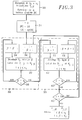
- the coding procedure carried out with conventional coding circuits, is illustrated in FIG. 2.
- the bits a j received successively from the source coder 11 are first arranged, in groups of k1 x k2 bits, according to a matrix ⁇ a ⁇ with k1 rows and k2 columns (step 21).
- the block code C2 is then applied to each of the k1 rows of the matrix ⁇ a ⁇ , which provides a matrix ⁇ b ⁇ with k1 rows and n2 columns (step 22).
- k2 of the n2 columns of the matrix ⁇ b ⁇ are identical to the matrix ⁇ a ⁇ , for example the first k2 columns.
- the block code C1 is applied to each of the n2 columns of the matrix ⁇ b ⁇ , which provides a matrix ⁇ c ⁇ with n1 rows and n2 columns whose components c j are the bits transmitted successively to the modulator 13 in the form of the signal Y (t) (step 24).
- k1 of the n1 lines of the matrix ⁇ c ⁇ are identical to the matrix ⁇ b ⁇ , for example the first k1 lines.
- the upper left part, of k1 rows and k2 columns, of the matrix ⁇ c ⁇ is identical to the matrix ⁇ a ⁇ , the other components of the matrix ⁇ c ⁇ being redundancy bits.
- All the columns of the matrix ⁇ c ⁇ are code words of the code C1.
- all the rows of the matrix ⁇ c ⁇ are code words of the code C2, since the elementary codes are linear.
- the channel decoder 17 applies an iterative decoding procedure, the general flow diagram of which is presented in FIG. 3. After reception of a block of n1 x n2 samples R j1, j2 (1 ⁇ j1 ⁇ n1, 1 ⁇ j2 ⁇ n2) of the signal R (t) received from the demodulator 16, which corresponds to the emission of a coded block formed by the channel coder 12, these samples are stored in an input matrix ⁇ R ⁇ with n1 rows and n2 columns (step 30).
- the iterative decoding comprises a number m of decoding cycles.
- Each decoding cycle successively comprises a step 32 of searching for words of code C1 in the columns of the data matrix, and a step 33 of searching for words of code C2 in the rows of the data matrix.
- each search step 32 or 33 new values of the components of the decision matrix ⁇ D ⁇ and of the data matrix ⁇ R ' ⁇ which are used for the next search step are calculated.
- Each search step 32 or 33 can be seen as a filtering applied to the data matrix ⁇ R ' ⁇ to reduce the incidence of the noise samples B j1, j2 on the components R' j1, j2 of this matrix.
- Steps 32 and 33 are essentially identical if one swaps the role of rows and columns of the matrices.
- the counting variable i is incremented by one, and the column index j2 is initialized to 1.
- a word is decoded, according to the code C1 data corresponding to the j2-th column of the matrix ⁇ R ' ⁇ (step 37), which provides new values of the components D j, j2 and R j, j2 of the matrices ⁇ D ⁇ and ⁇ R' ⁇ (1 ⁇ j ⁇ n1).
- the decoding step 37 is followed by a comparison 38 between the column index j2 and the number of columns n2.
- the index j2 is incremented by one unit (step 39), then the decoding step 37 is repeated.
- the other step 33 of searching for code words of the current decoding cycle is started.
- the counting variable i is incremented by one, and the line index j1 is initialized to 1.
- a word is decoded, according to the code C2 data corresponding to the j1-th row of the matrix ⁇ R ' ⁇ (step 42), which provides new values of the components D j1, j and R' j1, j of the matrices ⁇ D ⁇ and ⁇ R ' ⁇ .
- the decoding step 42 is followed by a comparison 43 between the line index j1 and the parameter n1 of the code C1.
- the index j1 is incremented by one unit (step 44), then the decoding step 42 is repeated.
- the step 33 of searching for code words is finished, and the counting variable i is compared with 2m (test 45).
- i remains less than 2m, we return to search step 32 to start the next decoding cycle.
- the i becomes equal to 2m the m decoding cycles having been completed, the k1 x k2 information bits decoded at j1, j2 are extracted (step 46) from the decision matrix ⁇ D ⁇ produced during the last step 33 code word search.
- Step 37 of decoding a data word corresponding to a column of the data matrix is detailed in the flowchart of FIG. 4.
- a data vector [R '] and a decision vector [D], of length n1 constituting respectively subdivisions of the data matrix ⁇ R' ⁇ and of the decision matrix ⁇ D ⁇ :
- step 51 the p least reliable components of the vector [R '], that is to say the components of [R'] which are closest to the binary decision threshold (zero).
- the indices corresponding to these least reliable p components are denoted r1, r2, rp, with etc ...
- an algebraic decoding of the decision vector [D] and of the q words [U s ] is carried out.
- a Berlekamp decoder is used, which is well known in the field of block coding (see ER Berlekamp, "Algebric Coding Theory", M c Graw-Hill, New York, 1968).
- the q + 1 elementary decodings provide q 'code words [C1] [C q' ] of the code C1.
- the component index j is initialized to 1.
- a test step 56 is carried out to determine whether, among the q 'code words found in the step 53, there exists at least one [C s ] having its j-th component different from that of the selected code word [C d ] ( C j s ⁇ C j d ). If there exists one or more code words [C s ] satisfying this condition, the smallest Euclidean distance M c between the data vector [R '] and any of these code words is determined (step 57) :
- the code word [C c ] which presents this distance M c with respect to the data vector [R '] is called concurrent word relative to the j-th component.
- the component W j is then calculated in step 58 according to the formula:
- the quantity M c -M d involved in this formula is always positive so that
- M c -M d .
- the component index j is compared to the length n1 of the vector [R '] (step 60). When j remains less than n1, the index j is incremented by one unit (step 61), and the next iteration is carried out starting with test 56.
- the loop is ended, and the decoding step 37 ends with the updating 62 of the data vector [R '] and the decision vector [D].
- the new decision vector [D] is taken equal to the code word [C d ] selected in step 54.
- Other formulas involving a confidence coefficient could still be used when no competing word is identified.
- the decision vector determined in the previous iteration does not intervene in the calculation loop of the correction vector [W]
- the steps 42 for decoding data words corresponding to lines of the data matrix are similar to the steps 37 detailed above with reference to FIG. 4, replacing the code C1 by the code C2, and the length n1 by the length n2, and by dividing the matrices ⁇ R ' ⁇ , ⁇ D ⁇ , ⁇ R ⁇ not in column vectors [R'], [D], [R], but in row vectors.
- the confidence coefficients ⁇ i and ⁇ i are assigned an index which corresponds to the counting variable i in the flowchart in Figure 3. Indeed, these coefficients ⁇ i , ⁇ i can vary from one research step 32, 33 to another. Preferably, the ⁇ i and ⁇ i increase as the code word search steps 32, 33 increase, to take account of the increasing reliability of the decoding.
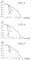
- the Applicant has tried the method described above with reference to FIGS. 1 to 4 for different codes produced in the context of digital simulations.
- the modulation considered for the transmitted signal was a two-state phase modulation (MDP2), and the propagation channel was modeled by an additive white noise Gaussian channel.
- MDP2 two-state phase modulation
- BCH Bose-Chaudhuri-Hocquenghem
- curve A corresponds to the case where block coding is not applied, for comparison purposes
- the concurrent word [C c ] is not chosen from the code words resulting from algebraic decodings.
- the decision vector [D] is considered to be the only possible concurrent word relative to each component W j , although it does not necessarily constitute a code word C1. Consequently, there is no need to decode as many words as in the first embodiment.
- the flowchart of Figure 3 remains valid for the second embodiment, as the steps 51 to 54 illustrated in FIG. 4.
- the loop for calculating the components W j of the correction vectors [W] can be carried out as shown in FIG. 8.
- the index j is compared to the length n1 of the vector [R '] (step 600). When j remains less than n1, the index j is incremented by one (step 610), and the next iteration is carried out starting with test 560. When j becomes equal to n1, we go to step 62 updating vectors [R '] and [D] as in the case of FIG. 4.
- steps 53 and 54 can be carried out (FIG. 4) as illustrated in FIG. 9.
- the counting variable t is initialized and the distance M d at a arbitrarily large number (step 524).
- step 525 the algebraic decoding of the t-th word to be decoded is carried out to obtain a binary word [E t ] (there are in total q + 1 words to be decoded: the old vector of decision [D] and the q words [U s ] constructed in step 52). If the code C1 is not a perfect code, one checks in 526 if the binary word [E t ] belongs to the code C1, by multiplying it by the matrix of checking of parity of the code C1. If not, the word [E t ] is eliminated and we compare, in 527, the variable t to the number q + 1. When t becomes equal to q + 1, all the decoding has been done and we go to step 550 described previously with reference to FIG. 8. If the comparison 527 shows that t remains less than q + 1, the variable t is incremented by one at 528 and we return to the decoding step 525 for the next word.
- a verification loop of the components of the word [E t ] is carried out.
- the component index j is initialized to 1 and the number L to 0.
- step 532 we add to the number L the quantity ( E j t -R j ') 2. Then, we compare the component index j to the length n1 of the vectors (test 533). If j ⁇ n1, the test 533 is followed by an incrementation 534 of the index j, and by the comparison 530 relating to the following iteration.
- the word [E t ] has been accepted for all its components (in other words sup ⁇
- the numbers L and M d are compared (test 535). If L ⁇ M d , the new value of M d is taken equal to L, in 536, and the word [C d ] is taken equal to [E t ], then we go to test 527. If test 535 shows that L ⁇ M d , we pass directly to test 527. Thus when all the decodings have been made and the words obtained verified (test 527 positive), the word [C d ] is the acceptable code word having the smallest Euclidean distance by relation to the vector [R '], and this minimum distance is equal to M d . We then proceed to the process illustrated in FIG. 8.
- step 526 is deleted, the decoding 525 being directly followed by the initialization 529 of the verification loop of the components of the word [E t ].
- the threshold ⁇ i is assigned an index which corresponds to the counting variable i in the flowchart of FIG. 3.
- the threshold ⁇ i increases as the steps of searching for code words 32, 33 to take into account the increasing reliability of decoding.
- FIG. 9 shows a certain overlapping between the functions corresponding to blocks 53 and 54 in FIG. 4. It will be understood that the order of execution of the main functions of the invention as well as the possible nesting of these functions can vary to a fairly large extent, this being essentially a matter of choice to be made when programming the decoder processing circuits.
- FIG. 10 shows the BER obtained for different values of the Eb / N0 ratio in the case of Example 4.
- Curve A corresponds to the case where block coding is not applied
- the second embodiment represents an excellent compromise between the decoding performance and the complexity of implementation.
- the first execution mode has the best performance (improvement of around 0.7 dB for a BER of 10 ⁇ 5), and could be adopted in particular in applications where the simplicity of implementation is not a critical factor.
- the decoding procedure of the method according to the invention can be carried out according to a flowchart which differs somewhat from those illustrated above.
- a correction matrix ⁇ W ⁇ whose components are calculated, for each column or row, as shown in steps 58 and 59 in Figure 4 or in steps 580 and 590 in Figure 8.
- the last step 62 of the flowchart in Figure 4 is not part of the decoding steps 37 or 42.
- the matrices ⁇ R ' ⁇ , ⁇ R ⁇ and ⁇ W ⁇ being linked, it is equivalent, to transmit the data matrix, to store ⁇ R ⁇ and ⁇ R' ⁇ as indicated previously, or to store ⁇ R ⁇ and ⁇ W ⁇ .
- the algebraic decodings carried out in steps 53 or 525 can be carried out by means of conventional decoder circuits.
- a single decoder circuit is moreover necessary when the elementary codes are the same.
- the rest of the iterative decoding procedure can easily be performed by programming an appropriate processor, or by using a specific circuit.
- the method according to the invention is applicable to the case where the product code results from the product of more than two elementary codes.
- the matrices processed are then more than two dimensions, and each decoding cycle comprises a corresponding number of steps for searching for code words.
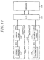
- Figure 11 shows a variant of the transmission chain of Figure 1 in which the transmission channel propagation includes a memory 130, for example a memory with magnetic tapes or digital optical disks.
- the transmitter 110 produces a coded digital signal Y (t) which a channel coder 112 obtains in the manner described above from information bits X (t) supplied by a data input device 111.
- the device d input 111 can be a source encoder as explained above. It can also be a computer delivering data to be stored, this computer being able moreover to perform the functions of the channel encoder 112.
- the coded signal Y (t) is addressed, directly or via a transmission line at the interface 120 of the memory 130 for writing.
- a receiver 115 for receiving the information thus stored comprises a channel decoder 117 connectable directly or indirectly to the interface 120 for reading a signal R (t) generally having a certain distortion with respect to the write signal Y (t).
- the decoder 117 applies one of the methods described above to provide an estimation signal Z (t).
- This signal Z (t) is supplied to a processing device 118.
- the processing applied by the device 118 may include, for example, other storage of the information Z (t), calculations based on this information, or a representation of a physical entity that characterizes this information (display of animated or non-animated images, sound reproduction, printing of a document ).
- the device 118 will often include processing circuits further ensuring the functions of the decoder 117.
Abstract
Description
La présente invention concerne les transmissions numériques, dans lesquelles on utilise un codage en blocs pour corriger des erreurs de transmission.The present invention relates to digital transmissions, in which block coding is used to correct transmission errors.
En matière de transmission numérique de l'information (parole, image, données...), on distingue habituellement entre le codage source et le codage canal. Le codage source forme la représentation binaire du signal à transmettre. Il est normalement conçu en fonction de la nature du signal à transmettre. Beaucoup d'efforts ont été effectués ces dernières années en matière de codage source pour réduire le débit numérique tout en conservant une bonne qualité de transmission. Mais ces nouvelles techniques de codage source nécessitent une meilleure protection des bits vis-à-vis des perturbations lors de la transmission. D'autre part, les limitations physiques et économiques des composants haute fréquence (facteur de bruit, saturation de la puissance) ainsi que la réglementation sur le niveau de puissance autorisé à l'émission limitent la portée des systèmes de transmission numérique.In terms of digital transmission of information (speech, image, data, etc.), a distinction is usually made between source coding and channel coding. Source coding forms the binary representation of the signal to be transmitted. It is normally designed according to the nature of the signal to be transmitted. Much effort has been made in recent years in source coding to reduce digital throughput while maintaining good transmission quality. However, these new source coding techniques require better protection of the bits against disturbances during transmission. On the other hand, the physical and economic limitations of high frequency components (noise factor, power saturation) as well as the regulations on the power level authorized for transmission limit the range of digital transmission systems.
C'est pourquoi beaucoup de travaux ont été effectués en matière de codage canal, en particulier en matière de codage en blocs. Ce type de codage correcteur d'erreurs consiste à ajouter, à k bits d'information issus du codage source, n-k bits de redondance, et à utiliser ces bits de redondance à la réception pour corriger certaines erreurs de transmission. On appelle rendement du code le rapport R=k/n, et on définit le gain de codage G comme le rapport, exprimé en décibels, entre les énergies par bit d'information Eb nécessaires à l'entrée du récepteur sans codage et avec codage pour atteindre un taux d'erreur binaire (TEB) donné. Un objectif typique est de réaliser des codeurs et surtout les décodeurs associés de façon que : (i) le gain de codage G soit le plus élevé (G > 5 dB pour TEB = 10⁻⁵), (ii) le rendement du code soit le plus élevé (R > 0,6), et (iii) la complexité de décodage soit la plus faible.This is why a lot of work has been done on channel coding, in particular on block coding. This type of error correcting coding consists in adding, to k bits of information originating from the source coding, nk redundancy bits, and in using these redundancy bits on reception to correct certain transmission errors. The ratio R = k / n is called code efficiency, and the coding gain G is defined as the ratio, expressed in decibels, between the energies per bit of information Eb necessary for the input of the receiver without coding and with coding. to reach a given bit error rate (BER). A typical objective is to produce coders and above all the associated decoders so that: (i) the coding gain G is the highest (G> 5 dB for TEB = 10⁻⁵), (ii) the efficiency of the code is the highest (R> 0.6), and (iii) the decoding complexity is the lowest.
Le cas du stockage de l'information numérique peut être vu comme un cas particulier de la transmission, dans lequel le canal de propagation inclut une mémoire dans laquelle l'information reste stockée plus ou moins longtemps, l'émetteur et le récepteur pouvant être confondus ou non. On comprendra donc qu'en général, les notions de codage canal et de décodage associé sont applicables au domaine du stockage de l'information de la même manière qu'à la transmission, les erreurs à corriger étant alors celles dues à la lecture ou à l'écriture dans la mémoire, à l'altération du contenu de la mémoire ou encore aux communications (à distance ou non) avec les dispositifs de lecture et d'écriture dans la mémoire.The case of the storage of digital information can be seen as a particular case of transmission, in which the propagation channel includes a memory in which the information remains stored for more or less long, the transmitter and the receiver being able to be confused. or not. It will therefore be understood that in general, the concepts of channel coding and associated decoding are applicable to the field of information storage in the same way as to transmission, the errors to be corrected then being those due to reading or to writing to memory, altering the contents of memory or even communications (remote or not) with devices for reading and writing to memory.
Il est connu d'améliorer les performances des codes correcteurs d'erreurs en utilisant des techniques de concaténation. En particulier, la technique des codes produits, qui est plus précisément concernée par la présente invention, permet d'obtenir à partir de deux codes en blocs simples (c'est-à-dire ayant une faible distance de Hamming minimale d), un code dont la distance de Hamming minimale est égale au produit des distances de Hamming des codes élémentaires utilisés.It is known to improve the performance of error correcting codes by using concatenation techniques. In particular, the technique of product codes, which is more precisely concerned with the present invention, makes it possible to obtain, from two codes in simple blocks (that is to say having a small minimum Hamming distance d), a code whose minimum Hamming distance is equal to the product of the Hamming distances of the elementary codes used.
Si on désigne par C₁ un code en blocs de paramètres (n₁,k₁,d₁) et par C₂ un code en blocs de paramètres (n₂,k₂,d₂), l'application du code produit de C₁ par C₂ consiste à ordonner les k₁ x k₂ bits d'information successifs dans une matrice, et à coder les k₁ lignes de la matrice par le code C₂, puis les n₂ colonnes de la matrice résultante par le code C₁. Les paramètres du code produit P sont alors donnés par (n = n₁ x n₂ ; k = k₁ x k₂ ; d = d₁ x d₂). rendement R du code P est égal à R₁ x R₂. Le décodage du code P suivant le maximum de vraisemblance a posteriori (MVP) permet d'atteindre les performances optimales. Le gain de codage asymptotique maximal peut alors être approché par la relation G < 10 log₁₀ (R.d).If we designate by C₁ a code in parameter blocks (n₁, k₁, d₁) and by C₂ a code in parameter blocks (n₂, k₂, d₂), the application of the product code of C₁ by C₂ consists in ordering the k₁ x k₂ successive bits of information in a matrix, and to code the k₁ rows of the matrix by the code C₂, then the n₂ columns of the resulting matrix by the code C₁. The parameters of the product code P are then given by (n = n₁ x n₂; k = k₁ x k₂; d = d₁ x d₂). yield R of the code P is equal to R₁ x R₂. Decoding the code P following the maximum posterior likelihood (MVP) achieves optimal performance. The maximum asymptotic coding gain can then be approximated by the relation G <10 log₁₀ (Rd).
Le code produit est donc très intéressant, mais le décodage suivant le MVP est généralement trop complexe, sauf dans le cas de codes en blocs courts.The product code is therefore very interesting, but the decoding according to the MVP is generally too complex, except in the case of short block codes.
Dans l'article "On decoding iterated codes", IEEE Trans. on Information theory, Vol. IT-16, N° 5, Septembre 1970, pages 624-627, S.M. Reddy, propose un algorithme de décodage d'un code produit construit à partir de codes élémentaires décodables par un décodeur algébrique, qui peut se résumer en trois étapes :
- décoder les colonnes de la matrice de codage en utilisant un décodeur algébrique,
- générer, pour chaque colonne, une estimation de la fiabilité des bits décodés basée sur le nombre de bits corrigés, et
- décoder les lignes par un décodeur algébrique en exploitant la fiabilité déterminée lors du décodage des colonnes.
- decode the columns of the coding matrix using an algebraic decoder,
- generate, for each column, an estimate of the reliability of the decoded bits based on the number of corrected bits, and
- decode the lines by an algebraic decoder by exploiting the reliability determined during the decoding of the columns.
Cet algorithme de décodage est sous optimal par rapport au MVP, et ne permet pas d'exploiter pleinement toutes les ressources du code produit.This decoding algorithm is suboptimal compared to the MVP, and does not allow to fully exploit all the resources of the product code.
Dans leur article "Separable MAP filters for the decoding of product and concatenated codes", Proc. ICC'93, Genève, Pages 1740-1745, Mai 1993, J. Lodge et al. ont proposé un algorithme itératif de décodage comprenant les étapes suivantes :
- décoder les colonnes en utilisant l'algorithme de Bahl (voir L.R.Bahl et al, "Optimal decoding of linear codes for minimizing symbol error rate", IEEE Trans. on Information Theory, Vol. IT-20, pages 248-287, Mars 1974) qui estime les rapports logarithmiques de vraisemblance (LLR pour "Log-Likelihood-Ratio") des bits,
- décoder les lignes en utilisant l'algorithme de Bahl et en prenant comme données d'entrée les vraisemblances (LLR) calculées lors du décodage des colonnes, et
- recommencer le décodage des colonnes avec pour données d'entrée les vraisemblances (LLR) calculées lors du décodage des lignes.
- decode columns using Bahl's algorithm (see LRBahl et al, "Optimal decoding of linear codes for minimizing symbol error rate", IEEE Trans. on Information Theory, Vol. IT-20, pages 248-287, March 1974) which estimates the logarithmic likelihood ratios (LLR for "Log-Likelihood-Ratio") of the bits,
- decode the lines using the algorithm of Bahl and taking as input data the likelihoods (LLR) calculated during the decoding of the columns, and
- restart the decoding of the columns with the likelihood data (LLR) calculated during the decoding of the rows as input data.
On réitère plusieurs fois le décodage des colonnes suivi par le décodage des lignes. Cet algorithme, bien qu'il conduise à des performances supérieures à celles de l'algorithme de Reddy, n'est applicable que pour des codes de longueur faible, par exemple le code de Hamming (16,11,3). Ceci est dû au fait que l'algorithme de Bahl utilise le treillis associé aux codes en blocs, qui croît exponentiellement en fonction de n-k. Cet algorithme n'est donc pas utilisable en pratique pour des codes de rendement élevés tels que, par exemple, le code BCH (63,51,5).The column decoding is repeated several times followed by the row decoding. This algorithm, although it leads to higher performances than those of Reddy's algorithm, is only applicable for codes of short length, for example the Hamming code (16,11,3). This is due to the fact that the Bahl algorithm uses the lattice associated with block codes, which grows exponentially as a function of n-k. This algorithm cannot therefore be used in practice for high efficiency codes such as, for example, the BCH code (63,51,5).
Un but de la présente invention est de proposer un procédé de transmission de bits d'information faisant appel à un mode de décodage des codes produits qui soit bien adapté au cas des codes de rendement élevé.An object of the present invention is to provide a method of transmitting information bits using a decoding mode of the product codes which is well suited to the case of high efficiency codes.
L'invention propose ainsi un procédé pour détecter des bits d'information dans un signal numérique codé, au niveau d'un récepteur, le codage dudit signal numérique ayant été effectué au niveau d'un émetteur en appliquant à des bits d'information à transmettre un code en blocs correspondant au produit d'au moins deux codes en blocs systématiques élémentaires, le procédé comprenant une phase de décodage itératif incluant un nombre m de cycles de décodage, chaque cycle de décodage comportant successivement des étapes de recherche de mots de code pour chaque code en blocs élémentaire utilisé dans le code produit. A chaque étape de recherche de mots de code, on reçoit une matrice de données et une matrice de décision à composantes binaires qui, avant la première étape de recherche de la phase de décodage itératif, sont respectivement constituées par une matrice d'entrée composée d'échantillons du signal reçu et par une matrice dont les composantes sont celles de la matrice d'entrée mises sous forme binaire, et on produit une nouvelle matrice de décision et une nouvelle matrice de données pour l'étape de recherche suivante. Les bits d'information décodés sont extraits de la matrice de décision produite lors de la dernière étape de recherche de mots de codes. Chaque étape de recherche de mots de code comporte une division de la matrice de données reçue en vecteurs de données correspondant chacun à un mot de code du code élémentaire et une division correspondante de la matrice de décision reçue en vecteurs de décision, et les sous-étapes suivantes pour traiter respectivement certains au moins des couples vecteur de données/vecteur de décision:
- détermination d'un nombre p d'indices pour lesquels les composantes du vecteur de données sont les moins fiables ;
- construction d'un nombre q de mots binaires à décoder à partir desdits p indices et du vecteur de décision;
- obtention de q' mots de code sur la base de décodages algébriques du vecteur de décision et des q mots binaires à décoder ;
- sélection, parmi les q' mots de code obtenus, de celui ayant la plus faible distance euclidienne avec le vecteur de données ;
- calcul d'un vecteur de correction, chaque composante Wj du vecteur de correction étant respectivement calculée en déterminant un éventuel mot concurrent ayant sa j-ième composante différente de celle du mot de code sélectionné, et en appliquant la formule :

- obtention du nouveau vecteur de décision pris égal audit mot de code sélectionné; et
- calcul du nouveau vecteur de données en ajoutant le vecteur de correction multiplié par un premier coefficient de confiance au vecteur d'entrée correspondant extrait de la matrice d'entrée.
- determination of a number p of indices for which the components of the data vector are the least reliable;
- construction of a number q of binary words to be decoded from said p indices and from the decision vector;
- obtaining q 'code words based on algebraic decoding of the decision vector and q binary words to be decoded;
- selection, among the q 'code words obtained, of the one having the lowest Euclidean distance with the data vector;
- calculation of a correction vector, each component W j of the correction vector being respectively calculated by determining a possible concurrent word having its jth component different from that of the selected code word, and by applying the formula:
- obtaining the new decision vector taken equal to said selected code word; and
- calculation of the new data vector by adding the correction vector multiplied by a first confidence coefficient to the corresponding input vector extracted from the input matrix.
De préférence, le calcul de chaque composante Wj du vecteur de correction en l'absence de détermination d'un mot concurrent relativement à cette composante est effectué selon la formule :![]()
où β i désigne un second coefficient de confiance. Le fait de ne pas trouver de mot concurrent pour un bit j signifie généralement que l'estimation de ce bit par le mot de code qui vient d'être sélectionné est relativement fiable. C'est pourquoi on prévoit une correction Wj proportionnelle à la composante correspondante du mot sélectionné, le facteur de proportionnalité β i étant de préférence croissant au fur et à mesure des étapes de recherche de mots de code.Preferably, the computation of each component W j of the correction vector in the absence of determination of a competing word relative to this component is carried out according to the formula: ![]()
where β i denotes a second confidence coefficient. The fact of not finding a concurrent word for a bit j generally means that the estimation of this bit by the code word which has just been selected is relatively reliable. This is why a correction W j is provided which is proportional to the corresponding component of the selected word, the proportionality factor β i preferably increasing with the steps of searching for code words.
Dans un premier mode d'exécution du procédé, procurant des performances de décodage optimales, la détermination d'un éventuel mot concurrent relativement à la j-ième composante du mot de code sélectionné comprend la détermination, parmi les q' mots de code obtenus, de ceux ayant leur j-ième composante différente de celle du mot de code sélectionné et la sélection comme mot concurrent de celui des mots de code ainsi déterminés ayant la plus petite distance euclidienne avec le vecteur de données, aucun mot concurrent n'étant déterminé lorsque les q' mots de code obtenus ont tous leur j-ième composante égale à celle du mot de code sélectionné. On souhaite en général que les composantes du vecteur de correction soient calculées en identifiant un mot concurrent et en appliquant la formule (1) dans les cas où l'estimation des bits correspondants est relativement peu fiable. Le premier mode d'exécution exposé ci-dessus, dans lequel on décode typiquement un nombre relativement élevé de mots binaires, donne lieu à une bonne probabilité de trouver à la fois le mot de code optimal et les meilleurs mots concurrents potentiels pour les composantes relativement peu fiables, de sorte que chaque itération d'une étape de recherche de mots de code permet d'améliorer sensiblement la fiabilité des décisions.In a first embodiment of the method, providing optimal decoding performance, the determination of a possible concurrent word relative to the j-th component of the selected code word comprises the determination, among the q 'code words obtained, of those having their j-th component different from that of the selected code word and the selection as a competing word from that of the code words thus determined having the smallest Euclidean distance with the data vector, no competing word being determined when the q 'code words obtained all have their jth component equal to that of the word of selected code. It is generally desired that the components of the correction vector be calculated by identifying a concurrent word and by applying formula (1) in cases where the estimation of the corresponding bits is relatively unreliable. The first embodiment described above, in which a relatively large number of binary words are typically decoded, gives rise to a good probability of finding both the optimal code word and the best potential competing words for the relatively components. unreliable, so that each iteration of a code word search step can significantly improve the reliability of decisions.
Le fait d'avoir à décoder un nombre relativement important de mots binaires à chaque itération (typiquement q ≧ 15) nécessite une puissance de calcul non négligeable. Pour certains décodeurs, on pourra préférer réduire quelque peu les performances en termes de TEB pour faciliter notablement la mise en oeuvre du décodage. Une possibilité est d'appliquer le second mode d'exécution du procédé selon l'invention, dans lequel la détermination d'un éventuel mot concurrent relativement à la j-ième composante du mot de code sélectionné comprend une comparaison entre la j-ième composante du vecteur de décision et celle du mot de code sélectionné, le vecteur de décision étant pris comme mot concurrent lorsque sa j-ième composante est différente de celle du mot de code sélectionné, et aucun mot concurrent n'étant déterminé dans le cas contraire. On peut alors réduire sensiblement le nombre q des mots binaires à décoder (typiquement q ≦ 6) puisqu'il suffit de trouver un mot de code optimal parmi les résultats des q + 1 décodages, sans avoir à trouver en plus des mots concurrents potentiels pour les différentes composantes peu fiables du vecteur d'entrée, le vecteur de décision obtenu à l'itération précédente étant le seul mot concurrent candidat.The fact of having to decode a relatively large number of binary words at each iteration (typically q ≧ 15) requires significant computing power. For certain decoders, it may be preferable to reduce performance somewhat in terms of BER to significantly facilitate the implementation of decoding. One possibility is to apply the second embodiment of the method according to the invention, in which the determination of a possible competing word relative to the j-th component of the selected code word comprises a comparison between the j-th component of the decision vector and that of the selected code word, the decision vector being taken as the competing word when its j-th component is different from that of the selected code word, and no competing word being determined otherwise. We can then significantly reduce the number q of binary words to be decoded (typically q ≦ 6) since it suffices to find an optimal code word among the results of the q + 1 decodings, without having to additionally find potential competing words for the various unreliable components of the input vector, the decision vector obtained in the previous iteration being the only candidate candidate word.
Bien entendu, la simplification apportée par le second mode d'exécution par rapport au premier a pour contrepartie une certaine dégradation des performances de décodage. Cette dégradation peut être acceptable pour certaines applications, et elle peut d'ailleurs être limitée par des dispositions appropriées. Selon l'une de ces dispositions, l'obtention des q' mots de code comprend, pour chaque mot de code résultant du décodage algébrique du vecteur de décision ou d'un des q mots binaires à décoder, l'identification des composantes du vecteur d'entrée associé ayant un signe contraire de celui de la composante correspondante dudit mot de code, ledit mot de code étant retenu parmi les q' mots de code uniquement si les valeurs absolues desdites composantes de signe contraire du vecteur d'entrée sont toutes inférieures à un seuil préétabli. On évite ainsi de modifier des éléments binaires fiables, notamment lors des premières itérations. De préférence, le seuil précité est croissant au fur et à mesure des étapes de recherche de mots de code.Of course, the simplification brought by the second mode of execution compared to the first has as a counterpart a certain degradation of the decoding performances. This degradation may be acceptable for certain applications, and it may moreover be limited by appropriate provisions. According to one of these provisions, obtaining the q 'code words comprises, for each code word resulting from the algebraic decoding of the decision vector or from one of the q binary words to be decoded, the identification of the components of the vector associated input having a sign opposite to that of the corresponding component of said code word, said code word being retained from the q 'code words only if the absolute values of said components of opposite sign of the input vector are all less at a preset threshold. This avoids modifying reliable bits, especially during the first iterations. Preferably, the aforementioned threshold increases as the code word search steps are carried out.
Un second aspect de l'invention se rapporte à un procédé pour transmettre des bits d'information, comprenant : une phase de codage dans laquelle on applique aux bits d'information à transmettre un code en blocs correspondant au produit d'au moins deux codes en blocs systématiques élémentaires ; une phase de modulation et d'émission d'un signal obtenu à partir des bits d'information codés ; une phase de réception du signal émis après propagation et de démodulation ; et une phase de décodage itératif exécutée conformément au procédé ci-dessus exposé, pour détecter les bits d'information dans le signal reçu après démodulation.A second aspect of the invention relates to a method for transmitting information bits, comprising: a coding phase in which a block code corresponding to the product of at least two codes is applied to the information bits to be transmitted in elementary systematic blocks; a phase of modulation and transmission of a signal obtained from the coded information bits; a phase of reception of the signal transmitted after propagation and of demodulation; and an iterative decoding phase executed in accordance with the method described above, for detecting the information bits in the signal received after demodulation.
Un troisième aspect de l'invention se rapporte à un procédé pour restituer des bits d'information stockés sous forme codée dans une mémoire, le codage desdits bits ayant été effectué en appliquant un code en blocs correspondant au produit d'au moins deux codes en blocs systématiques élémentaires, ledit procédé comprenant une phase de lecture dans la mémoire et une phase de décodage itératif effectuée conformément au procédé ci-dessus exposé, pour détecter les bits d'information dans le signal fourni par la phase de lecture.A third aspect of the invention relates to a method for restoring bits of information stored in coded form in a memory, the coding of said bits having been carried out by applying a block code corresponding to the product of at least two codes in elementary systematic blocks, said method comprising a phase of reading in the memory and an iterative decoding phase carried out in accordance with the method described above, for detecting the information bits in the signal supplied by the read phase.
D'autres particularités et avantages de la présente invention apparaîtront dans la description ci-après d'un exemple de réalisation préféré mais non limitatif, lue conjointement aux dessins annexés, dans lesquels :
- la figure 1 est un schéma synoptique d'une chaîne de transmission numérique utilisable pour mettre en oeuvre le procédé selon l'invention ;
- la figure 2 est un organigramme illustrant l'application d'un code produit ;
- la figure 3 est un organigramme général d'une phase de décodage itératif selon l'invention ;
- la figure 4 est un organigramme détaillant une étape de décodage de ligne ou de colonne selon un premier mode d'exécution de l'invention ;
- les figures 5 à 7 sont des graphiques illustrant des performances du décodage itératif selon le premier mode d'exécution, dans trois exemples de codes produits ;
- la figure 8 illustre partiellement une variante de l'organigramme de la figure 4 selon un second mode d'exécution de l'invention ;
- la figure 9 est un organigramme montrant une façon de sélectionner les mots de code dans le second mode d'exécution ;
- la figure 10 est un graphique comparatif illustrant les performances des premier et second modes d'exécution de l'invention ; et
- la figure 11 est un schéma synoptique d'un système de stockage d'information numérique utilisable pour mettre en oeuvre l'invention.
- Figure 1 is a block diagram of a digital transmission chain used to implement the method according to the invention;
- Figure 2 is a flow diagram illustrating the application of a product code;
- Figure 3 is a general flowchart of an iterative decoding phase according to the invention;
- Figure 4 is a flowchart detailing a step of decoding row or column according to a first embodiment of the invention;
- FIGS. 5 to 7 are graphs illustrating the performance of iterative decoding according to the first embodiment, in three examples of product codes;
- Figure 8 partially illustrates a variant of the flow diagram of Figure 4 according to a second embodiment of the invention;
- Fig. 9 is a flowchart showing a way of selecting the code words in the second embodiment;
- FIG. 10 is a comparative graph illustrating the performance of the first and second embodiments of the invention; and
- FIG. 11 is a block diagram of a digital information storage system usable for implementing the invention.
Dans la chaîne de transmission illustrée sur la figure 1, les bits d'information à transmettre aj sont contenus dans un signal![]()
adressé à l'entrée du codeur canal 12 de l'émetteur 10. Ce signal X(t) est formé par le codeur source 11 à partir d'un signal analogique S(t). Le codeur source 11 est classiquement tel que les aj soient indépendants et prennent de manière équiprobable la valeur 0 ou 1. h(t) désigne une porte temporelle de durée T qui est l'intervalle de temps séparant deux bits successifs. Le codeur canal 12 applique un codage en blocs pour produire un signal![]()
où les cj sont les bits codés et T' est l'intervalle de temps séparant deux bits codés (T'< T). Le modulateur 13 transforme la séquence Y(t) en séquences de signaux compatibles avec le canal de propagation. Dans le cas d'une modulation de phase à deux états associé à un canal hertzien, un exemple du signal émis est donné par:![]()
où f₀ est la fréquence de l'onde porteuse et ej = 2. cj - 1. Le signal reçu au niveau de l'antenne du récepteur 15 est atténué par un coefficient α. Le démodulateur 16 élabore le rapport de vraisemblance de chaque bit qui peut s'écrire :![]()
où les échantillons Bj sont les échantillons de bruit induits par le canal de propagation, indépendants des bits Cj, et non-corrélés entre eux, de moyenne nulle et d'écart type σ, fonction du rapport signal à bruit. Le signal à la sortie du démodulateur 16 est alors égal à :![]()
![]()
addressed to the input of the ![]()
where the c j are the coded bits and T 'is the time interval separating two coded bits (T'<T). The ![]()
where f₀ is the frequency of the carrier wave and e j = 2. c j - 1. The signal received at the antenna of the ![]()
where the samples B j are the noise samples induced by the propagation channel, independent of the bits C j , and uncorrelated with each other, of zero mean and of standard deviation σ, function of the signal to noise ratio. The signal at the output of the ![]()
Le décodeur canal 17 prend ensuite la décision concernant les bits émis en exploitant le codage canal utilisé à l'émission pour minimiser les erreurs. Son signal de sortie est donné par :![]()
où les bits âj sont les décisions prises par le décodeur canal. Le décodeur source 18 reconstruit ensuite le signal analogique S(t) à partir des bits fournis par le décodeur canal 17.The ![]()
where the bits â j are the decisions made by the channel decoder. The
L'invention réside principalement dans le codeur canal 12 et le décodeur canal 17. On comprendra donc qu'elle est compatible avec divers types de codage/décodage source, de modulation/démodulation et de canaux de propagation. En particulier, l'invention peut s'appliquer dans le cadre de la télévision numérique. Le codeur 11 et le décodeur 18 peuvent alors être réalisés selon une norme MPEG (moving picture expert group), par exemple, et le modulateur 13 et le démodulateur 16 sont adaptés au canal de propagation utilisé (hertzien, filaire ....). Un autre exemple d'application est la transmission de télécopies.The invention mainly resides in the
Le code en blocs appliqué par le codeur canal 12 est un code produit obtenu à partir de codes élémentaires systématiques. Dans le mode de réalisation décrit ci-après, c'est le produit de deux codes en blocs linéaires C₁, C₂ de paramètres respectifs (n₁,k₁,d₁) et (n₂,k₂,d₂).The block code applied by the
La procédure de codage, réalisée avec des circuits de codage classiques, est illustrée sur la figure 2. Les bits aj reçus successivement du codeur source 11 sont d'abord rangés, par groupes de k₁ x k₂ bits, selon une matrice {a} à k₁ lignes et k₂ colonnes (étape 21). Le code en blocs C₂ est alors appliqué à chacune des k₁ lignes de la matrice {a}, ce qui fournit une matrice {b} à k₁ lignes et n₂ colonnes (étape 22). Comme le code C₂ est systématique, k₂ des n₂ colonnes de la matrice {b} sont identiques à la matrice {a}, par exemple les k₂ premières colonnes. Ensuite (étape 23), le code en blocs C₁ est appliqué à chacune des n₂ colonnes de la matrice {b}, ce qui fournit une matrice {c} à n₁ lignes et n₂ colonnes dont les composantes cj sont les bits transmis successivement au modulateur 13 sous la forme du signal Y(t) (étape 24). Comme le code C₁ est systématique, k₁ des n₁ lignes de la matrice {c} sont identiques à la matrice {b}, par exemple les k₁ premières lignes. Ainsi, la partie supérieure gauche, de k₁ lignes et k₂ colonnes, de la matrice {c} est identique à la matrice {a}, les autres composantes de la matrice {c} étant des bits de redondance. Toutes les colonnes de la matrice {c} sont des mots de code du code C₁. De même, toutes les lignes de la matrice {c} sont des mots de code du code C₂, étant donné que les codes élémentaires sont linéaires.The coding procedure, carried out with conventional coding circuits, is illustrated in FIG. 2. The bits a j received successively from the
Le décodeur canal 17 applique une procédure de décodage itératif dont l'organigramme général est présenté sur la figure 3. Après réception d'un bloc de n₁ x n₂ échantillons Rj1,j2 (1 ≦ j1 ≦ n₁, 1 ≦ j2 ≦ n₂) du signal R(t) reçu du démodulateur 16, qui correspond à l'émission d'un bloc codé formé par le codeur canal 12, ces échantillons sont rangés dans une matrice d'entrée {R} à n₁ lignes et n₂ colonnes (étape 30).The
Le décodage de ce bloc de n₁ x n₂ échantillons est initialisé (étape 31) en initialisant à 0 la variable de comptage i, en formant une matrice de données {R'} à n₁ lignes et n₂ colonnes dont les composantes sont initialement les mêmes que celles de la matrice d'entrée {R}, et en formant une matrice de décision {D} à n₁ lignes et n₂ colonnes dont les composantes sont binaires (-1 ou +1) et, initialement, représentent chacune le signe de la composante correspondante de la matrice d'entrée {R} :![]()
![]()
Après cette initialisation, le décodage itératif comporte un nombre m de cycles de décodage. Chaque cycle de décodage comporte successivement une étape 32 de recherche de mots du code C₁ dans les colonnes de la matrice de données, et une étape 33 de recherche de mots du code C₂ dans les lignes de la matrice de données.After this initialization, the iterative decoding comprises a number m of decoding cycles. Each decoding cycle successively comprises a step 32 of searching for words of code C₁ in the columns of the data matrix, and a
A chaque étape de recherche 32 ou 33, on calcule de nouvelles valeurs des composantes de la matrice de décision {D} et de la matrice de données {R'} qui sont utilisées pour l'étape de recherche suivante. Chaque étape de recherche 32 ou 33 peut être vue comme un filtrage appliqué à la matrice de données {R'} pour réduire l'incidence des échantillons de bruit Bj1,j2 sur les composantes R'j1,j2 de cette matrice.At each
Les étapes 32 et 33 sont essentiellement identiques si on permute le rôle de lignes et des colonnes des matrices. A l'initialisation 36 de l'étape de recherche 32, la variable de comptage i est incrémentée d'une unité, et l'indice de colonne j2 est initialisé à 1. On effectue un décodage, selon le code C₁, du mot de données correspondant à la j2-ième colonne de la matrice {R'} (étape 37), ce qui fournit de nouvelles valeurs des composantes Dj,j2 et Rj,j2 des matrices {D} et {R'} (1 ≦ j ≦ n₁). L'étape de décodage 37 est suivie par une comparaison 38 entre l'indice de colonne j2 et le nombre de colonnes n₂. Lorsque j2 reste inférieur à n₂, l'indice j2 est incrémenté d'une unité (étape 39), puis l'étape de décodage 37 est répétée. Lorsque j2 devient égal à n₂, toutes les colonnes ayant été traitées, on commence l'autre étape 33 de recherche de mots de code du cycle de décodage en cours. A l'initialisation 41 de l'étape de recherche 33, la variable de comptage i est incrémentée d'une unité, et l'indice de ligne j1 est initialisé à 1. On effectue un décodage, selon le code C₂, du mot de données correspondant à la j1-ième ligne de la matrice {R'} (étape 42), ce qui fournit de nouvelles valeurs des composantes Dj1,j et R'j1,j des matrices {D} et {R'}. L'étape de décodage 42 est suivie par une comparaison 43 entre l'indice de ligne j1 et le paramètre n₁ du code C₁. Lorsque j1 reste inférieur à n₁, l'indice j1 est incrémenté d'une unité (étape 44), puis l'étape de décodage 42 est répétée. Lorsque j1 devient égal à n₁, l'étape 33 de recherche de mots de code est terminée, et la variable de comptage i est comparée à 2m (test 45). Lorsque i reste inférieur à 2m, on revient à l'étape de recherche 32 pour commencer le cycle de décodage suivant. Lorsque i devient égal à 2m, les m cycles de décodage ayant été accomplis, on extrait (étape 46) les k₁ x k₂ bits d'information décodés âj1,j2 de la matrice de décision {D} produite lors de la dernière étape 33 de recherche de mots de code. Avec les codes systématiques C₁, C₂ appliqués de la façon décrite plus haut en référence à la figure 2, les âj1,j2 peuvent être simplement récupérés dans les k₁ premières lignes et les k₂ premières colonnes de la matrice {D} : âj1,j2 = Dj1,j2 (1 ≦ j1 ≦ k₁, 1 ≦ j2 ≦ k₂). Ces âj1,j2 sont à valeurs -1 ou +1 ; ils peuvent aisément être convertis pour prendre les valeurs 0 ou 1.
L'étape 37 de décodage d'un mot de données correspondant à une colonne de la matrice de données, dans un premier mode d'exécution de l'invention, est détaillée sur l'organigramme de la figure 4. Lors de cette étape 37, on traite un vecteur de données [R'] et un vecteur de décision [D], de longueur n₁, constituant respectivement des subdivisions de la matrice de données {R'} et de la matrice de décision {D} : R'j = R'j,j2 et Dj = Dj,j2 (1 ≦ j ≦ n₁). On repère d'abord (étape 51) les p composantes les moins fiables du vecteur [R'], c'est-à-dire les composantes de [R'] qui sont les plus proches du seuil de décision binaire (zéro). Les indices correspondant à ces p composantes les moins fiables sont notés r1, r2, rp, avec![]()
![]()
etc...![]()
![]()
etc ...
Ayant identifié ces p indices, on construit q séquences binaires de test [T¹],...,[Tq] de longueur n₁, puis q mots binaires à décoder [U¹],..., [Uq] de longueur n₁ en combinant chacune des q séquences de test avec le vecteur de décision [D] (étape 52). On construit chaque mot [Us] de façon que toutes ses composantes autres que celles correspondant aux p indices r1, ...,rp soient égales aux composantes correspondantes du vecteur de décision [D] U j s = D j pour j ≠ r1, ..., rp. Il suffit généralement de prendre en compte des mots [Us] qui n'ont qu'une ou deux composantes différentes des composantes correspondantes du vecteur [D]. Tous ces mots sont pris en compte lorsque q = p(p+1)/2. A titre d'exemple, lorsque p = 6 et q = 21, on peut construire les séquences [Ts] et [US] (1 ≦ s ≦ q) de la façon suivante :
- * les p = 6 premières séquences de test [TS] ont un bit égal à +1 en position rs et des bits égaux à -1 aux autres positions : T rs s = +1 et T j s = -1 pour 1 ≦ s ≦ 6 et j ≠ rs ;
- * [T⁷] = [T¹] ⊕ [T²] [T¹⁵] = [T²] ⊕ [T⁶]
[T⁸] = [T¹] ⊕ [T³] [T¹⁶] = [T³] ⊕ [T⁴]
[T⁹] = [T¹] ⊕ [T⁴] [T¹⁷] = [T³] ⊕ [T⁵]
[T¹⁰] = [T¹] ⊕ [T⁵] [T¹⁸] = [T³] ⊕ [T⁶]
[T¹¹] = [T¹] ⊕ [T⁶] [T¹⁹] = [T⁴] ⊕ [T⁵]
[T¹²] = [T²] ⊕ [T³] [T²⁰] = [T⁴] ⊕ [T⁶]
[T¹³] = [T²] ⊕ [T⁴] [T²¹] = [T⁵] ⊕ [T⁶]
[T¹⁴] = [T²] ⊕ [T⁵] où ⊕ désigne l'opération OU exclusif, composante par composante, entre deux vecteurs ; - * [Us] = [Ts] ⊕ [D] pour 1 ≦ s ≦ q
- * the p = 6 first test sequences [T S ] have a bit equal to +1 at position rs and bits equal to -1 at the other positions: T rs s = +1 and T j s = - 1 for 1 ≦ s ≦ 6 and j ≠ rs;
- * [T⁷] = [T¹] ⊕ [T²] [T¹⁵] = [T²] ⊕ [T⁶]
[T⁸] = [T¹] ⊕ [T³] [T¹⁶] = [T³] ⊕ [T⁴]
[T⁹] = [T¹] ⊕ [T⁴] [T¹⁷] = [T³] ⊕ [T⁵]
[T¹⁰] = [T¹] ⊕ [T⁵] [T¹⁸] = [T³] ⊕ [T⁶]
[T¹¹] = [T¹] ⊕ [T⁶] [T¹⁹] = [T⁴] ⊕ [T⁵]
[T¹²] = [T²] ⊕ [T³] [T²⁰] = [T⁴] ⊕ [T⁶]
[T¹³] = [T²] ⊕ [T⁴] [T²¹] = [T⁵] ⊕ [T⁶]
[T¹⁴] = [T²] ⊕ [T⁵] where ⊕ denotes the exclusive OR operation, component by component, between two vectors; - * [U s ] = [T s ] ⊕ [D] for 1 ≦ s ≦ q
A l'étape suivante 53, on effectue un décodage algébrique du vecteur de décision [D] et des q mots [Us]. Pour ce décodage algébrique, on utilise par exemple, dans le cas de codes BCH, un décodeur de Berlekamp, qui est bien connu dans le domaine du codage par blocs (voir E.R. Berlekamp, "Algebric Coding Theory", Mc Graw-Hill, New-York, 1968). Les q + 1 décodages élémentaires fournissent q' mots de codes [C¹] [Cq'] du code C₁. Dans le cas général, q' ≦ q + 1, car d'une part certains mots de code peuvent apparaître plusieurs fois dans les résultats des décodages, et d'autre part le décodeur algébrique peut ne pas trouver certains mots de code si le signal est très perturbé. Les mots four-nis comme résultats du décodage algébrique doivent donc être vérifiés pour déterminer s'ils constituent ou non des mots du code C₁. Cette vérification peut s'effectuer simplement en multipliant chaque mot obtenu par la matrice de vérification de parité relative au code C₁ et en éliminant le mot si le résultat de la multiplication n'est pas nul. Toutefois, dans le cas où le code C₁ est parfait (c'est-à-dire tel qu'aucun mot de n₁ bits n'est éloigné de tous les mots de codes possibles de plus de (d₁-1)/2, ce qui est le cas notamment pour les codes de Hamming), l'étape de vérification des résultats du décodeur algébrique est inutile.In the
Parmi les q' mots de codes trouvés, on sélectionne (étape 54) celui [Cd] qui présente la plus faible distance euclidienne Md = ∥[Cd] - [R']∥² avec le vecteur de données [R'].Among the q 'code words found, we select (step 54) the one [C d ] which has the lowest Euclidean distance M d = ∥ [C d ] - [R'] ∥² with the data vector [R ' ].
On effectue ensuite une boucle de calcul des composantes Wj d'un vecteur de correction [W] (1 ≦ j ≦ n₁). Au début de cette boucle (étape 55), l'indice de composante j est initialisé à 1. A chaque itération dans cette boucle, on effectue une étape de test 56 pour déterminer si, parmi les q' mots de code trouvés à l'étape 53, il en existe au moins un [Cs] ayant sa j-ième composante différente de celle du mot de code sélectionné [Cd] (C j s ≠C j d ). S'il existe un ou plusieurs mots de code [Cs] vérifiant cette condition, on détermine (étape 57) la plus petite distance euclidienne Mc entre le vecteur de données [R'] et l'un quelconque de ces mots de code :
Le mot de code [Cc] qui présente cette distance Mc par rapport au vecteur de données [R'] est appelé mot concurrent relativement à la j-ième composante. La composante Wj est alors calculée à l'étape 58 selon la formule :![]()
![]()
On observera que la quantité Mc-Md intervenant dans cette formule est toujours positive de sorte que |Mc-Md| = Mc-Md. Si l'étape de test 56 ne révèle aucun mot de code [Cs] tel que C j s ≠ C j d , c'est-à-dire si aucun mot concurrent ne peut être déterminé, la composante Wj est calculée à l'étape 59 selon la formule :![]()
où βi désigne un coefficient de confiance positif. Après calcul de la composante de correction Wj, l'indice de composante j est comparé à la longueur n₁ du vecteur [R'] (étape 60). Lorsque j reste inférieur à n₁, l'indice j est incrémenté d'une unité (étape 61), et l'itération suivante est effectuée en commençant par le test 56.It will be observed that the quantity M c -M d involved in this formula is always positive so that | M c -M d | = M c -M d . If the ![]()
where β i denotes a positive confidence coefficient. After calculating the correction component W j , the component index j is compared to the length n₁ of the vector [R '] (step 60). When j remains less than n₁, the index j is incremented by one unit (step 61), and the next iteration is carried out starting with
Lorsque j devient égal à n₁, la boucle est terminée, et l'étape de décodage 37 se termine par la mise à jour 62 du vecteur de données [R'] et du vecteur de décision [D]. Le nouveau vecteur [R'] est pris égal à la somme du vecteur d'entrée [R] (dont chaque composante Rj est extraite de la matrice d'entrée {R} : Rj = Rj,j2), et du vecteur de correction [W] multiplié par un autre coefficient de confiance positif αi : [R'] = [R] + αi [W]. Le nouveau vecteur de décision [D] est pris égal au mot de code [Cd] sélectionné à l'étape 54.When j becomes equal to n₁, the loop is ended, and the
Dans une variante avantageuse du premier mode d'exécution de l'invention, la formule (2) appliquée le cas échéant à l'étape 59 est remplacée par :![]()
qui procure une correction Wj directement proportionnelle au signe de la nouvelle décision C j d . D'autres formules faisant intervenir un coefficient de confiance pourraient encore être utilisées lorsqu'aucun mot concurrent n'est identifié.In an advantageous variant of the first embodiment of the invention, the formula (2) applied where appropriate in ![]()
which provides a correction W j directly proportional to the sign of the new decision C j d . Other formulas involving a confidence coefficient could still be used when no competing word is identified.
Etant donné que, dans le premier mode d'exécution de l'invention, le vecteur de décision déterminé à l'itération précédente n'intervient pas dans la boucle de calcul du vecteur de correction [W], il est indifférent de mettre à jour le vecteur de décision [D] avant cette boucle (par exemple après l'étape de sélection 54) ou après cette boucle (par exemple en même temps que la mise à jour 62 du vecteur de données [R'] comme l'illustre la figure 4).Since, in the first embodiment of the invention, the decision vector determined in the previous iteration does not intervene in the calculation loop of the correction vector [W], it is immaterial to set update the decision vector [D] before this loop (for example after the selection step 54) or after this loop (for example at the same time as the
Les étapes 42 de décodage de mots de données correspondant à des lignes de la matrice de données sont semblables aux étapes 37 détaillées ci-dessus en référence à la figure 4, en remplaçant le code C₁ par le code C₂, et la longueur n₁ par la longueur n₂, et en divisant les matrices {R'}, {D}, {R} non pas en vecteurs colonnes [R'], [D], [R], mais en vecteurs lignes.The
Les coefficients de confiance α i et β i sont affectés d'un indice qui correspond à la variable de comptage i de l'organigramme de la figure 3. En effet, ces coefficients αi, βi peuvent varier d'une étape de recherche 32, 33 à une autre. De préférence, les αi et βi croissent au fur et à mesure des étapes de recherche de mots de code 32, 33, pour tenir compte de la fiabilité croissante du décodage.The confidence coefficients α i and β i are assigned an index which corresponds to the counting variable i in the flowchart in Figure 3. Indeed, these coefficients α i , β i can vary from one
La demanderesse a essayé le procédé décrit ci-dessus en référence aux figures 1 à 4 pour différents codes produits dans le cadre de simulations numériques. La modulation considérée pour le signal émis était une modulation de phase à deux états (MDP2), et le canal de propagation était modélisé par un canal à bruit blanc additif gaussien. Les séquences de test [Ts] et les mots à décoder [Us] étaient déterminés à l'étape 52 de la façon détaillée plus haut, avec p = 6 et q = 21. Des résultats sont exposés ci-après dans le cas de trois codes produits de rendements élevés, obtenus à partir de codes systématiques élémentaires de type Bose-Chaudhuri-Hocquenghem (BCH).The Applicant has tried the method described above with reference to FIGS. 1 to 4 for different codes produced in the context of digital simulations. The modulation considered for the transmitted signal was a two-state phase modulation (MDP2), and the propagation channel was modeled by an additive white noise Gaussian channel. The test sequences [T s ] and the words to be decoded [U s ] were determined in
Le code BCH (63,57,3) est un code de Hamming et est donc parfait. Le code produit présente alors les propriétés suivantes :
- distance de Hamming minimale d = 9
- rendement de codage R = 0,82
- gain de codage G < 8,7 dB
- minimum Hamming distance d = 9
- coding efficiency R = 0.82
- coding gain G <8.7 dB
Les coefficients de confiance α₁, βi ont été choisis de la façon suivante :
α₁ = 0,2 β₁ = 0,5
α₂ = 0,3 β₂ = 0,5
α₃ = 0,4 β₃ = 1,0
α₄ = 0,4 β₄ = 1,5
α₅ = 0,5 β₅ = 1,5
α₆ = 0,5 β₆ = 2,0
α₇ = 0,7 β₇ = 2,0
α₈ = 0,7 β₈ = 3,0
α₉ = 0,8 β₉ = 3,0
α₁₀ = 0,8 β₁₀ = 4,0The confidence coefficients α₁, β i were chosen as follows:
α₁ = 0.2 β₁ = 0.5
α₂ = 0.3 β₂ = 0.5
α₃ = 0.4 β₃ = 1.0
α₄ = 0.4 β₄ = 1.5
α₅ = 0.5 β₅ = 1.5
α₆ = 0.5 β₆ = 2.0
α₇ = 0.7 β₇ = 2.0
α₈ = 0.7 β₈ = 3.0
α₉ = 0.8 β₉ = 3.0
α₁₀ = 0.8 β₁₀ = 4.0
Le code produit présente alors les propriétés suivantes :
- distance de Hamming minimale d = 25
- rendement de codage R = 0,66
- gain de codage G < 12 dB
- minimum Hamming distance d = 25
- coding efficiency R = 0.66
- coding gain G <12 dB
Les coefficients de confiance αi, βi ont été choisis de la façon suivante :
α₁ = 0,3 β₁ = 0,5
α₂ = 0,3 β₂ = 0,5
α₃ = 0,4 β₃ = 1,0
α₄ = 0,4 β₄ = 1,5
α₅ = 0,5 β₅ = 1,5
α₆ = 0,5 β₆ = 2,0
α₇ = 0,5 β₇ = 2,0
α₈ = 0,5 β₈ = 3,0
α₉ = 0,6 β₉ = 3,0
α₁₀ = 0,6 β₁₀ = 5,0The confidence coefficients α i , β i were chosen as follows:
α₁ = 0.3 β₁ = 0.5
α₂ = 0.3 β₂ = 0.5
α₃ = 0.4 β₃ = 1.0
α₄ = 0.4 β₄ = 1.5
α₅ = 0.5 β₅ = 1.5
α₆ = 0.5 β₆ = 2.0
α₇ = 0.5 β₇ = 2.0
α₈ = 0.5 β₈ = 3.0
α₉ = 0.6 β₉ = 3.0
α₁₀ = 0.6 β₁₀ = 5.0
Le code produit présente alors les propriétés suivantes :
- distance de Hamming minimale d = 25
- rendement de codage R = 0,79
- gain de codage G < 13 dB
- minimum Hamming distance d = 25
- coding efficiency R = 0.79
- coding gain G <13 dB
Les coefficients de confiance αi, βi ont été choisis de la même façon que dans l'exemple 2.The confidence coefficients α i , β i were chosen in the same way as in Example 2.
Dans chacun des trois exemples, on a estimé la dépendance entre le taux d'erreur binaire (TEB) et le rapport Eb/N0, exprimé en décibels, entre l'énergie Eb du signal émis par bit d'information et la densité spectrale N0 de la puissance du bruit induit lors de la propagation. Les résultats pour les exemples 1, 2 et 3 sont illustrés respectivement sur les graphiques des figures 5, 6 et 7.In each of the three examples, the dependence between the bit error rate (BER) and the ratio Eb / N0, expressed in decibels, between the energy Eb of the signal transmitted by information bit and the spectral density N0 has been estimated. of the power of the noise induced during propagation. The results for Examples 1, 2 and 3 are illustrated respectively in the graphs of Figures 5, 6 and 7.
Dans chacun de ces graphiques, la courbe A correspond au cas où le codage par blocs n'est pas appliqué, à des fins de comparaison, la courbe B correspond au cas où on réalise m = 1 cycles de décodage (c'est-à-dire 2m = 2 étapes de recherche de mots de code 32, 33), la courbe C correspond au cas où on réalise m = 3 cycles de décodage, et la courbe D correspond au cas où on réalise m = 5 cycles de décodage. On peut ainsi apprécier l'amélioration sur le taux d'erreur binaire procurée par la procédure itérative de décodage.In each of these graphs, curve A corresponds to the case where block coding is not applied, for comparison purposes, curve B corresponds to the case where m = 1 decoding cycles are carried out (i.e. - say 2m = 2 steps to search for code words 32, 33), curve C corresponds to the case where m = 3 decoding cycles are carried out, and curve D corresponds to the case where m = 5 decoding cycles are carried out. We can thus appreciate the improvement in the bit error rate provided by the iterative decoding procedure.
Dans le second mode d'exécution de l'invention, le mot concurrent [Cc] n'est pas choisi parmi les mots de codes issus des décodages algébriques. Le vecteur de décision [D] est considéré comme le seul mot concurrent possible relativement à chaque composante Wj, bien qu'il ne constitue pas nécessairement un mot du code C₁. En conséquence, on n'a pas besoin de décoder autant de mots que dans le premier mode d'exécution. Typiquement, on aura p = q = 3, chaque mot à décoder [Us] différant du vecteur de décision [D] par une seule de ses composantes. L'organigramme de la figure 3 reste valable pour le second mode d'exécution, de même que les étapes 51 à 54 illustrées sur la figure 4. La boucle de calcul des composantes Wj des vecteurs de correction [W] peut être effectuée de la manière représentée sur la figure 8. A l'initialisation 550 de l'indice de composante j, on calcule en outre la distance Mc = ∥ [D] - [R'] ∥² entre le mot concurrent candidat [D] et le vecteur de données [R']. A chaque itération dans la boucle, on compare (test 560) les j-ièmes composantes respectives du vecteur de décision [D] et du mot de code [Cd] sélectionné à l'étape 54. Si D j = C j d , aucun mot concurrent n'est retenu relativement à la j-ième composante, et on prend W j = βi C j d à l'étape 590. Si D j ≠ C j d le vecteur [D] est retenu comme mot concurrent et on calcule, à l'étape 580 :![]()
![]()
Après le calcul de la composante de correction Wj, l'indice j est comparé à la longueur n₁ du vecteur [R'] (étape 600). Lorsque j reste inférieur à n₁, l'indice j est incrémenté d'une unité (étape 610), et l'itération suivante est effectuée en commençant par le test 560. Lorsque j devient égal à n₁, on passe à l'étape 62 de mise à jour des vecteurs [R'] et [D] comme dans le cas de la figure 4.After the computation of the correction component W j , the index j is compared to the length n₁ of the vector [R '] (step 600). When j remains less than n₁, the index j is incremented by one (step 610), and the next iteration is carried out starting with
Le fait de prendre le vecteur de décision [D] comme seul mot concurrent possible constitue un traitement moins précis que celui employé dans le premier mode de réalisation. On souhaite donc que ce traitement ne soit pas appliqué de manière à modifier des composantes initialement fiables du vecteur d'entrée [R], surtout lors des premières itérations. Pour cela, on peut effectuer les étapes 53 et 54 (figure 4) de la manière illustrée sur la figure 9. A l'issue de l'étape 52, on initialise la variable de comptage t à 1 et la distance Md à un nombre arbitrairement grand (étape 524). A l'étape 525, on effectue le décodage algébrique du t-ième mot à décoder pour obtenir un mot binaire [Et] (il y a au total q + 1 mots à décoder : l'an-cien vecteur de décision [D] et les q mots [Us] construits à l'étape 52). Si le code C₁ n'est pas un code parfait, on vérifie en 526 si le mot binaire [Et] appartient au code C₁, en le multipliant par la matrice de vérification de parité du code C₁. Dans la négative, le mot [Et] est éliminé et on compare, en 527, la variable t au nombre q + 1. Quand t devient égal à q+1, tous les décodages ont été faits et on passe à l'étape 550 décrite précédemment en référence à la figure 8. Si la comparaison 527 montre que t reste inférieur à q+1, la variable t est incrémentée d'une unité en 528 et on revient à l'étape de décodage 525 pour le mot suivant.Taking the decision vector [D] as the only possible competing word constitutes less precise treatment than that used in the first embodiment. It is therefore desired that this processing is not applied so as to modify initially reliable components of the input vector [R], especially during the first iterations. For this, steps 53 and 54 can be carried out (FIG. 4) as illustrated in FIG. 9. At the end of
Si la vérification de parité 526 montre que le mot [Et] appartient au code C₁, on effectue une boucle de vérification des composantes du mot [Et]. A l'initialisation 529 de cette boucle, l'indice de composante j est initialisé à 1 et le nombre L à 0. A chaque itération dans cette boucle on compare, en 530, le signe de la j-ième composante Rj du vecteur d'entrée [R] à la valeur binaire de la j-ième composante E j t du mot [Et]. Si sgn(R j ) = E j t , on passe à l'étape 532. La condition sgn(R j ) ≠ E j t traduit le fait que l'éventuelle sélection du mot [Et] inverserait le signe de la décision binaire par rapport à la valeur de Rj, ce qu'on souhaite interdire si cette valeur de Rj est relativement fiable. Ainsi, si la comparaison 530 montre que sgn R j ) ≠ E j t , on compare, en 531, la valeur absolue de Rj à un seuil γi. Si |Rj| > γi, la composante Rj est considérée comme fiable et on élimine donc le mot [Et] en passant directement au test 527. Si la comparaison 531 montre que |Rj| < γi, le mot [Et] est considéré comme acceptable en ce qui concerne sa j-ième composante, et on passe à l'étape 532. A l'étape 532, on ajoute au nombre L la quantité (E j t -R j ')². Ensuite, on compare l'indice de composante j à la longueur n₁ des vecteurs (test 533). Si j < n₁, le test 533 est suivi par une incrémentation 534 de l'indice j, et par la comparaison 530 relative à l'itération suivante. Si le test 533 montre que j = n₁, le mot [Et] a été accepté pour toutes ses composantes (en d'autres termes sup { |R j |/ sgn(R j ) ≠ E j t }< γi), et il fait alors partie des q' mots de code pouvant être sélectionnés pour former le prochain vecteur de décision, le nombre L étant égal à sa distance euclidienne par rapport au vecteur de données [R'].If the parity check 526 shows that the word [E t ] belongs to the code C₁, a verification loop of the components of the word [E t ] is carried out. At the
Une fois que le mot [Et] a été retenu parmi lesdits q' mots de code, on compare les nombres L et Md (test 535). Si L < Md, la nouvelle valeur de Md est prise égale à L, en 536, et le mot [Cd] est pris égal à [Et], puis on passe au test 527. Si le test 535 montre que L ≧ Md, on passe directement au test 527. Ainsi lorsque tous les décodages ont été faits et les mots obtenus vérifiés (test 527 positif), le mot [Cd] est le mot de code acceptable ayant la plus petite distance euclidienne par rapport au vecteur [R'], et cette distance minimale est égale à Md. On passe alors au processus illustré sur la figure 8.Once the word [E t ] has been retained among said q 'code words, the numbers L and M d are compared (test 535). If L <M d , the new value of M d is taken equal to L, in 536, and the word [C d ] is taken equal to [E t ], then we go to test 527. If
Si le code C₁ est parfait, l'étape 526 est supprimée, le décodage 525 étant directement suivi par l'initialisation 529 de la boucle de vérification des composantes du mot [Et].If the code C₁ is perfect,
Le seuil γi est affecté d'un indice qui correspond à la variable de comptage i de l'organigramme de la figure 3. De préférence, le seuil γi croît au fur et à mesure des étapes de recherche de mots de code 32, 33 pour tenir compte de la fiabilité croissante du décodage.The threshold γ i is assigned an index which corresponds to the counting variable i in the flowchart of FIG. 3. Preferably, the threshold γ i increases as the steps of searching for
L'organigramme de la figure 9 montre une certaine imbrication entre les fonctions correspondant aux blocs 53 et 54 sur la figure 4. On comprendra que l'ordre d'exécution des principales fonctions de l'invention ainsi que l'imbrication éventuelle de ces fonctions peuvent varier dans une assez large mesure, ceci étant essentiellement une question de choix à opérer lors de la programmation des circuits de traitement du décodeur.The flow diagram of FIG. 9 shows a certain overlapping between the functions corresponding to
Les procédures illustrées aux figures 8 et 9 ont été décrites dans le cadre des étapes 37 de décodage de mots de données correspondant à des colonnes de la matrice de données (figure 3) . Elles sont bien entendu directement transposables au cas des lignes (étapes de décodage 42).The procedures illustrated in Figures 8 and 9 have been described in the context of
La demanderesse a testé le second mode d'exécution du procédé, tel que décrit en référence aux figures 8 et 9 avec p = q = 3. Le type de canal considéré dans cette simulation était le même que celui des exemples 1 à 3. Le code produit présente les propriétés suivantes :
- distance de Hamming minimale d = 16
- rendement de codage R = 0,79
- gain de codage G < 11 dB
- minimum Hamming distance d = 16
- coding efficiency R = 0.79
- coding gain G <11 dB
Les coefficients αi, βi, γi ont été choisis de la façon suivante :
α₁ = 0,3 β₁ = 0,2 γ₁ = 0,5
α₂ = 0,5 β₂ = 0,3 γ₂ = 0,7
α₃ = 0,7 β₃ = 0,5 γ₃ = 1,0
α₄ = 0,9 β₄ = 0,7 γ₄ = 1,5
α₅ = 1,0 β₅ = 0,9 γ₅ = 2,0
α₆ = 1,1 β₆ = 1,0 γ₆ = 2,5
α₇ = 1,2 β₇ = 1,1 γ₇ = 3,0
α₈ = 1,2 β₈ = 1,2 γ₈ = 4,0The coefficients α i , β i , γ i were chosen as follows:
α₁ = 0.3 β₁ = 0.2 γ₁ = 0.5
α₂ = 0.5 β₂ = 0.3 γ₂ = 0.7
α₃ = 0.7 β₃ = 0.5 γ₃ = 1.0
α₄ = 0.9 β₄ = 0.7 γ₄ = 1.5
α₅ = 1.0 β₅ = 0.9 γ₅ = 2.0
α₆ = 1.1 β₆ = 1.0 γ₆ = 2.5
α₇ = 1.2 β₇ = 1.1 γ₇ = 3.0
α₈ = 1.2 β₈ = 1.2 γ₈ = 4.0
La figure 10 montre le TEB obtenu pour différentes valeurs du rapport Eb/N0 dans le cas de l'exemple 4. La courbe A correspond au cas où le codage par blocs n'est pas appliqué, la courbe B correspond à m = 4 cycles de décodage selon le second mode d'exécution du procédé, et la courbe C correspond à m = 4 cycles de décodage selon le premier mode d'exécution dans les mêmes conditions de simulation qu'aux exemples 1 et 3 et avec les valeurs des αi et βi indiquées ci-dessus. Le second mode d'exécution représente un excellent compromis entre les performances de décodage et la complexité de mise en oeuvre. Le premier mode d'exécution présente les meilleures performances (amélioration de l'ordre de 0,7 dB pour un TEB de 10⁻⁵), et pourra être adopté notamment dans les applications où la simplicité de mise en oeuvre n'est pas un facteur critique.FIG. 10 shows the BER obtained for different values of the Eb / N0 ratio in the case of Example 4. Curve A corresponds to the case where block coding is not applied, curve B corresponds to m = 4 cycles of decoding according to the second embodiment of the method, and the curve C corresponds to m = 4 decoding cycles according to the first embodiment under the same simulation conditions as in Examples 1 and 3 and with the values of the α i and β i indicated above. The second embodiment represents an excellent compromise between the decoding performance and the complexity of implementation. The first execution mode has the best performance (improvement of around 0.7 dB for a BER of 10⁻⁵), and could be adopted in particular in applications where the simplicity of implementation is not a critical factor.
Bien entendu, la procédure de décodage du procédé selon l'invention peut être exécutée selon un organigramme qui diffère quelque peu de ceux illustrés précédemment. Par exemple, au lieu de transmettre la matrice {R'} d'une étape de recherche de mots de code 32, 33 à la suivante, il est possible de transmettre une matrice de correction {W} dont les composantes sont calculées, pour chaque colonne ou ligne, comme indiqué aux étapes 58 et 59 sur la figure 4 ou aux étapes 580 et 590 sur la figure 8. Dans ce cas, la dernière étape 62 de l'organigramme de la figure 4 ne fait pas partie des étapes de décodage 37 ou 42. Les vecteurs de données [R'] sont formés au début de chaque étape de décodage 37 ou 42 en ajoutant à un vecteur ligne ou colonne [R] de la matrice d'entrée, le vecteur ligne ou colonne correspondant de la matrice {W}, multiplié par le coefficient αi-1 (avec α₀ = 0). Les matrices {R'}, {R} et {W} étant liées, il est équivalent, pour transmettre la matrice de données, de mémoriser {R} et {R'} comme indiqué précédemment, ou de mémoriser {R} et {W}.Of course, the decoding procedure of the method according to the invention can be carried out according to a flowchart which differs somewhat from those illustrated above. For example, instead of transmitting the matrix {R '} from one step of searching for
Les décodages algébriques effectués aux étapes 53 ou 525 peuvent être réalisés au moyen de circuits décodeurs classiques. Un seul circuit décodeur est d'ailleurs nécessaire lorsque les codes élémentaires sont les mêmes. Le reste de la procédure de décodage itératif peut aisément être effectué en programmant un processeur approprié, ou encore en utilisant un circuit spécifique.The algebraic decodings carried out in
On notera que le procédé selon l'invention est applicable au cas où le code produit résulte de produit de plus de deux codes élémentaires. Les matrices traitées sont alors à plus que deux dimensions, et chaque cycle de décodage comporte un nombre correspondant d'étapes de recherche de mots de code.It will be noted that the method according to the invention is applicable to the case where the product code results from the product of more than two elementary codes. The matrices processed are then more than two dimensions, and each decoding cycle comprises a corresponding number of steps for searching for code words.
La figure 11 montre une variante de la chaîne de transmission de la figure 1 dans laquelle le canal de propagation comprend une mémoire 130, par exemple une mémoire à bandes magnétiques ou à disques optiques numériques. L'émetteur 110 produit un signal numérique codé Y(t) qu'un codeur canal 112 obtient de la manière décrite précédemment à partir de bits d'information X(t) fournis par un dispositif d'entrée de données 111. Le dispositif d'entrée 111 peut être un codeur source comme exposé précédemment. Il peut également être un ordinateur délivrant des données à mémoriser, cet ordinateur pouvant d'ailleurs assurer en outre les fonctions du codeur canal 112. Le signal codé Y(t) est adressé, directement ou par l'intermédiaire d'une ligne de transmission à l'interface 120 de la mémoire 130 pour l'écriture. Un récepteur 115 pour recevoir l'information ainsi stockée comprend un décodeur canal 117 raccordable directement ou indirectement à l'interface 120 pour lire un signal R(t) présentant en général une certaine distorsion par rapport au signal d'écriture Y(t). Le décodeur 117 applique l'un des procédés décrits ci-dessus pour fournir un signal d'estimation Z(t). Ce signal Z(t) est fourni à un dispositif de traitement 118. Le traitement appliqué par le dispositif 118 peut comprendre par exemple une autre mémorisation de l'information Z(t), des calculs sur la base de cette information, ou une représentation d'une entité physique que caractérise cette information (affichage d'images animées ou non, restitution de son, impression d'un document...). Le dispositif 118 comprendra souvent des circuits de traitement assurant en outre les fonctions du décodeur 117.Figure 11 shows a variant of the transmission chain of Figure 1 in which the transmission channel propagation includes a
Claims (15)
caractérisé en ce que, à chaque étape (32,33) de recherche de mots de code, on reçoit une matrice de données ({R'}) et une matrice de décision ({D}) à composantes binaires qui, avant la première étape de recherche de la phase de décodage itératif, sont respectivement constituées par une matrice d'entrée ({R}) composée d'échantillons du signal reçu (R(t)) et par une matrice dont les composantes sont celles de la matrice d'entrée ({R}) mises sous forme binaire, et on produit une nouvelle matrice de décision ({D}) et une nouvelle matrice de données ({R'}) pour l'étape de recherche suivante, en ce que les bits d'information décodés (âj) sont extraits de la matrice de décision produite lors de la dernière étape de recherche de mots de code, et en ce que chaque étape (32,33) de recherche de mots de code comporte une division de la matrice de données reçue en vecteurs de données ([R']) correspondant chacun à un mot de code du code élémentaire et une division correspondante de la matrice de décision reçue en vecteurs de décision ([D]) et les sous-étapes suivantes pour traiter respectivement certains au moins des couples vecteur de données/vecteur de décision :
characterized in that, at each step (32,33) of searching for code words, one receives a data matrix ({R '}) and a decision matrix ({D}) with binary components which, before the first step of searching for the iterative decoding phase, are respectively constituted by an input matrix ({R}) composed of samples of the received signal (R (t)) and by a matrix whose components are those of the matrix d 'input ({R}) put in binary form, and we produce a new decision matrix ({D}) and a new data matrix ({R'}) for the next search step, in that the bits of decoded information (â j ) are extracted from the decision matrix produced during the last step of searching for code words, and in that each step (32,33) of searching for code words comprises a division of the data matrix received in data vectors ([R ']) each corresponding to a code word of the elementary code and a division n corresponding to the decision matrix received in decision vectors ([D]) and the following sub-steps for respectively processing at least some of the data vector / decision vector pairs:
Applications Claiming Priority (2)
| Application Number | Priority Date | Filing Date | Title |
|---|---|---|---|
| FR9313858A FR2712760B1 (en) | 1993-11-19 | 1993-11-19 | Method for transmitting bits of information by applying concatenated block codes. |
| FR9313858 | 1993-11-19 |
Publications (2)
| Publication Number | Publication Date |
|---|---|
| EP0654910A1 true EP0654910A1 (en) | 1995-05-24 |
| EP0654910B1 EP0654910B1 (en) | 1998-08-19 |
Family
ID=9453044
Family Applications (1)
| Application Number | Title | Priority Date | Filing Date |
|---|---|---|---|
| EP94402618A Expired - Lifetime EP0654910B1 (en) | 1993-11-19 | 1994-11-17 | Iterative decoding method for concatenated block codes |
Country Status (5)
| Country | Link |
|---|---|
| US (1) | US5563897A (en) |
| EP (1) | EP0654910B1 (en) |
| JP (1) | JP3242804B2 (en) |
| DE (1) | DE69412570T2 (en) |
| FR (1) | FR2712760B1 (en) |
Cited By (7)
| Publication number | Priority date | Publication date | Assignee | Title |
|---|---|---|---|---|
| EP0827285A1 (en) * | 1996-08-28 | 1998-03-04 | France Telecom | Information bits transmission process with error correction coding, and coder and decoder therefor |
| EP0827284A1 (en) * | 1996-08-28 | 1998-03-04 | France Telecom | Information bits transmission process with error correction coding, and coder and decoder therefor |
| FR2756996A1 (en) * | 1996-12-10 | 1998-06-12 | Philips Electronics Nv | DIGITAL TRANSMISSION SYSTEM AND METHOD COMPRISING A PRODUCT CODE COMBINED WITH MULTI-DIMENSIONAL MODULATION |
| EP0936743A1 (en) * | 1998-02-17 | 1999-08-18 | Koninklijke Philips Electronics N.V. | Iterative decoding for binary block codes |
| FR2778289A1 (en) * | 1998-05-04 | 1999-11-05 | Alsthom Cge Alcatel | ITERATIVE DECODING OF PRODUCT CODES |
| FR2801744A1 (en) * | 1999-11-26 | 2001-06-01 | Mathieu Arnaud | Improvement of iterative decoding of codes produced by adjoining a priori information |
| FR2871631A1 (en) * | 2004-06-10 | 2005-12-16 | Centre Nat Rech Scient | METHOD FOR ITERACTIVE DECODING OF BLOCK CODES AND CORRESPONDING DECODER DEVICE |
Families Citing this family (144)
| Publication number | Priority date | Publication date | Assignee | Title |
|---|---|---|---|---|
| JP2882302B2 (en) * | 1995-02-24 | 1999-04-12 | 株式会社日立製作所 | Information recording method and reproduction method |
| FR2741215B1 (en) * | 1995-11-14 | 1998-01-23 | Matra Communication | METHOD FOR TRANSMITTING A SEQUENCE OF INFORMATION BITS WITH SELECTIVE PROTECTION AGAINST TRANSMISSION ERRORS, CODING AND CORRECTION PROCESSES WHICH CAN BE IMPLEMENTED IN SUCH A TRANSMISSION METHOD |
| US5996104A (en) * | 1996-09-13 | 1999-11-30 | Herzberg; Hanan | System for coding system |
| US6048090A (en) * | 1997-04-23 | 2000-04-11 | Cirrus Logic, Inc. | Error correction and concurrent verification of a product code |
| US5920578A (en) * | 1997-04-23 | 1999-07-06 | Cirrus Logic, Inc. | Method and apparatus for efficiently processing a multi-dimensional code |
| DE59801578D1 (en) * | 1997-04-30 | 2001-10-31 | Siemens Ag | METHOD AND ARRANGEMENT FOR DETERMINING AT LEAST ONE DIGITAL SIGNAL VALUE FROM AN ELECTRICAL SIGNAL |
| US5974580A (en) * | 1997-07-23 | 1999-10-26 | Cirrus Logic, Inc. | Concurrent row/column syndrome generator for a product code |
| US6052815A (en) * | 1997-11-14 | 2000-04-18 | Cirrus Logic, Inc. | ECC system for generating a CRC syndrome over randomized data in a computer storage device |
| US5996105A (en) * | 1997-11-14 | 1999-11-30 | Cirrus Logic, Inc. | ECC system employing a data buffer for storing codeword data and a syndrome buffer for storing error syndromes |
| US5991911A (en) * | 1997-11-14 | 1999-11-23 | Cirrus Logic, Inc. | Concurrent generation of ECC error syndromes and CRC validation syndromes in a DVD storage device |
| FR2771228A1 (en) * | 1997-11-18 | 1999-05-21 | Philips Electronics Nv | DIGITAL TRANSMISSION SYSTEM, DECODER, AND DECODING METHOD |
| US6088387A (en) | 1997-12-31 | 2000-07-11 | At&T Corp. | Multi-channel parallel/serial concatenated convolutional codes and trellis coded modulation encoder/decoder |
| US6047395A (en) * | 1998-01-30 | 2000-04-04 | Cirrus Logic, Inc. | Error correction processor for correcting a multi-dimensional code by generating an erasure polynomial over one dimension for correcting multiple codewords in another dimension |
| US6272659B1 (en) | 1998-05-18 | 2001-08-07 | Cirrus Logic, Inc. | Error correction code processor employing adjustable correction power for miscorrection minimization |
| US6279132B1 (en) * | 1998-09-28 | 2001-08-21 | Trw Inc. | Concatenated error control method and system for a processing satellite uplink |
| EP1443657A1 (en) | 1998-09-28 | 2004-08-04 | Comtech Telecommunications Corp. | Turbo product code decoder |
| US6292918B1 (en) | 1998-11-05 | 2001-09-18 | Qualcomm Incorporated | Efficient iterative decoding |
| DE19856085A1 (en) * | 1998-12-04 | 2000-06-21 | Siemens Ag | Adaptive chained channel coding method |
| US6233709B1 (en) | 1998-12-07 | 2001-05-15 | Nokia Mobile Phones Ltd. | Dynamic iterative decoding for balancing quality of service parameters |
| US6499128B1 (en) | 1999-02-18 | 2002-12-24 | Cisco Technology, Inc. | Iterated soft-decision decoding of block codes |
| DE19934646C2 (en) * | 1999-07-16 | 2001-09-13 | Univ Dresden Tech | Method and device for iterative decoding of chained codes |
| FR2796780B1 (en) | 1999-07-21 | 2003-09-19 | Groupe Ecoles Telecomm | METHOD AND DEVICE FOR CODING WITH AT LEAST TWO CODING IN PARALLEL AND IMPROVED PERMUTATION, AND METHOD AND CORRESPONDING DECODING DEVICE |
| EP1085661B1 (en) * | 1999-09-14 | 2005-03-02 | Lucent Technologies Inc. | Channel decoder and method of channel decoding |
| US6400290B1 (en) | 1999-11-29 | 2002-06-04 | Altera Corporation | Normalization implementation for a logmap decoder |
| EP1234420A2 (en) * | 1999-12-03 | 2002-08-28 | Broadcom Corporation | Viterbi slicer for turbo codes |
| AU4710501A (en) | 1999-12-03 | 2001-06-18 | Broadcom Corporation | Interspersed training for turbo coded modulation |
| US6421804B1 (en) | 1999-12-20 | 2002-07-16 | Agere Systems Guardian Corp. | Generating reliability values for iterative decoding of block codes |
| IL133896A0 (en) * | 2000-01-06 | 2001-04-30 | Telescicom Ltd | Method and system for encoding data for transmission channels |
| US7356752B2 (en) * | 2000-03-14 | 2008-04-08 | Comtech Telecommunications Corp. | Enhanced turbo product codes |
| US6526531B1 (en) * | 2000-03-22 | 2003-02-25 | Agere Systems Inc. | Threshold detection for early termination of iterative decoding |
| EP1281241A2 (en) * | 2000-04-04 | 2003-02-05 | Advanced Hardware Architectures, Inc | Enhanced turbo product code decoder system |
| US6732327B1 (en) | 2000-05-05 | 2004-05-04 | Nokia Networks Oy | Scaled-feedback turbo decoder |
| US6289000B1 (en) | 2000-05-19 | 2001-09-11 | Intellon Corporation | Frame control encoder/decoder for robust OFDM frame transmissions |
| US6738942B1 (en) * | 2000-06-02 | 2004-05-18 | Vitesse Semiconductor Corporation | Product code based forward error correction system |
| US6909723B1 (en) | 2000-08-04 | 2005-06-21 | Intellon Corporation | Segment bursting with priority pre-emption and reduced latency |
| US7352770B1 (en) | 2000-08-04 | 2008-04-01 | Intellon Corporation | Media access control protocol with priority and contention-free intervals |
| US7298691B1 (en) | 2000-08-04 | 2007-11-20 | Intellon Corporation | Method and protocol to adapt each unique connection in a multi-node network to a maximum data rate |
| US6987770B1 (en) | 2000-08-04 | 2006-01-17 | Intellon Corporation | Frame forwarding in an adaptive network |
| US7469297B1 (en) | 2000-08-04 | 2008-12-23 | Intellon Corporation | Mechanism for using a quasi-addressed response to bind to a message requesting the response |
| US7254190B2 (en) * | 2000-09-01 | 2007-08-07 | Broadcom Corporation | Satellite receiver |
| EP1329025A1 (en) * | 2000-09-05 | 2003-07-23 | Broadcom Corporation | Quasi error free (qef) communication using turbo codes |
| US7117418B2 (en) * | 2000-09-11 | 2006-10-03 | Comtech Aha Corporation | Soft input-soft output forward error correction decoding for turbo codes |
| US7383485B2 (en) * | 2000-09-12 | 2008-06-03 | Broadcom Corporation | Fast min*- or max*-circuit in LDPC (low density parity check) decoder |
| US7360146B1 (en) | 2002-08-15 | 2008-04-15 | Broadcom Corporation | Inverse function of min*:min*- (inverse function of max*:max*-) |
| US7242726B2 (en) * | 2000-09-12 | 2007-07-10 | Broadcom Corporation | Parallel concatenated code with soft-in soft-out interactive turbo decoder |
| US6654926B1 (en) * | 2000-10-11 | 2003-11-25 | Itran Communications Ltd. | Soft decision maximum likelihood encoder and decoder |
| US6518892B2 (en) | 2000-11-06 | 2003-02-11 | Broadcom Corporation | Stopping criteria for iterative decoding |
| EP1410513A4 (en) | 2000-12-29 | 2005-06-29 | Infineon Technologies Ag | Channel codec processor configurable for multiple wireless communications standards |
| US6813742B2 (en) * | 2001-01-02 | 2004-11-02 | Icomm Technologies, Inc. | High speed turbo codes decoder for 3G using pipelined SISO log-map decoders architecture |
| WO2002078196A1 (en) * | 2001-03-22 | 2002-10-03 | University Of Florida | Method and coding means for error-correction utilizing concatenated parity and turbo codes |
| US7010052B2 (en) * | 2001-04-16 | 2006-03-07 | The Ohio University | Apparatus and method of CTCM encoding and decoding for a digital communication system |
| EP1407555A1 (en) * | 2001-05-09 | 2004-04-14 | Comtech Telecommunications Corp. | Low density parity check codes and low density turbo product codes |
| JP3876662B2 (en) * | 2001-08-03 | 2007-02-07 | 三菱電機株式会社 | Product code decoding method and product code decoding apparatus |
| WO2003015285A1 (en) * | 2001-08-09 | 2003-02-20 | Adaptive Networks, Inc. | Error correction process and mechanism |
| CN1471761A (en) * | 2001-08-28 | 2004-01-28 | 连宇通信有限公司 | Iterated decode method for cascading bloock code bases on subcode syndrome decode |
| KR100449578B1 (en) | 2001-09-14 | 2004-09-21 | 한국전자통신연구원 | Iterative decoding method for block turbo codes more than 3-dimensions |
| AU2002334863A1 (en) * | 2001-10-04 | 2003-04-14 | Comtech Aha Corporation | Method of decoding a turbo product code utilizing a scalable and hardware efficient forward error correction decoder |
| US6847760B2 (en) * | 2001-10-23 | 2005-01-25 | Georgia Tech Research Corporation | Spatially resolved equalization and forward error correction for multimode fiber links |
| US20030093741A1 (en) * | 2001-11-14 | 2003-05-15 | Cenk Argon | Parallel decoder for product codes |
| KR100456474B1 (en) * | 2001-12-08 | 2004-11-09 | 한국전자통신연구원 | Method for iterative decoding of block turbo code and Recording medium for iterative decoding program of block turbo code |
| FR2834146A1 (en) * | 2001-12-20 | 2003-06-27 | St Microelectronics Sa | A compact turbo-decoder having high efficiency, comprises two sets of processors for computing in parallel the syndromes and for updating in parallel the block, respectively |
| US6704376B2 (en) * | 2002-01-23 | 2004-03-09 | Bae Systems Information And Electronic Systems Integration Inc. | Power and confidence ordered low complexity soft turbomud with voting system |
| JP3889286B2 (en) * | 2002-01-31 | 2007-03-07 | 三菱電機株式会社 | Decoding method, decoding apparatus, and digital transmission system |
| US20030202563A1 (en) * | 2002-04-26 | 2003-10-30 | Arnab Das | Rate adaptation and antenna selection in a wireless communication system |
| US7657822B2 (en) * | 2002-05-31 | 2010-02-02 | Broadcom Corporation | True bit level decoding of TTCM (turbo trellis code modulation) of variable rates and signal constellations |
| US6954832B2 (en) * | 2002-05-31 | 2005-10-11 | Broadcom Corporation | Interleaver for iterative decoder |
| US7032164B2 (en) * | 2002-05-31 | 2006-04-18 | Broadcom Corporation | Efficient design to calculate extrinsic information for soft-in-soft-out (SISO) decoder |
| US7210092B1 (en) | 2002-05-31 | 2007-04-24 | Broadcom Corporation | Symbol by symbol variable constellation type and/or mapping capable communication device |
| US7111226B1 (en) | 2002-05-31 | 2006-09-19 | Broadcom Corporation | Communication decoder employing single trellis to support multiple code rates and/or multiple modulations |
| US7188301B1 (en) | 2002-05-31 | 2007-03-06 | Broadcom Corporation | Parallel concatenated turbo code modulation encoder |
| US7107512B2 (en) * | 2002-05-31 | 2006-09-12 | Broadcom Corporation | TTCM decoder design |
| US7085985B2 (en) * | 2002-05-31 | 2006-08-01 | Broadcom Corporation | Close two constituent trellis of a turbo encoder within the interleave block |
| US7093187B2 (en) * | 2002-05-31 | 2006-08-15 | Broadcom Corporation | Variable code rate and signal constellation turbo trellis coded modulation codec |
| US7472335B1 (en) | 2002-05-31 | 2008-12-30 | Broadcom Corporation | Symbol by symbol variable code rate capable communication device |
| US7321633B1 (en) | 2002-05-31 | 2008-01-22 | Broadcom Corporation | Determination of variable code rates for a rate control sequence |
| US7062700B2 (en) * | 2002-05-31 | 2006-06-13 | Broadcom Corporation | 16 QAM and 16 APSK TTCM (Turbo Trellis Coded Modulation) with minimum bandwidth efficiency of 3 bit/s/Hz using a rate 2/4 constituent encoder |
| US7065695B2 (en) * | 2002-05-31 | 2006-06-20 | Broadcom Corporation | Metric calculation design for variable code rate decoding of broadband trellis, TCM, or TTCM |
| US7137059B2 (en) * | 2002-11-20 | 2006-11-14 | Broadcom Corporation | Single stage implementation of min*, max*, min and /or max to perform state metric calculation in SISO decoder |
| US7120847B2 (en) | 2002-06-26 | 2006-10-10 | Intellon Corporation | Powerline network flood control restriction |
| US7826466B2 (en) | 2002-06-26 | 2010-11-02 | Atheros Communications, Inc. | Communication buffer scheme optimized for VoIP, QoS and data networking over a power line |
| US8149703B2 (en) | 2002-06-26 | 2012-04-03 | Qualcomm Atheros, Inc. | Powerline network bridging congestion control |
| WO2004004132A1 (en) * | 2002-07-01 | 2004-01-08 | Linkair Communications,Inc. | Iterative decoding method and apparatus for product code based on adjoint formula |
| US7729373B2 (en) * | 2002-07-02 | 2010-06-01 | Broadcom Corporation | Modified range requests enabling bandwidth requests and state of health reporting |
| US20040019842A1 (en) * | 2002-07-24 | 2004-01-29 | Cenk Argon | Efficient decoding of product codes |
| US7694210B2 (en) * | 2002-07-31 | 2010-04-06 | Broadcom Corporation | Turbo-coding DOCSIS information for satellite communication |
| US7395487B2 (en) * | 2002-08-15 | 2008-07-01 | Broadcom Corporation | Common circuitry supporting both bit node and check node processing in LDPC (Low Density Parity Check) decoder |
| US7178080B2 (en) * | 2002-08-15 | 2007-02-13 | Texas Instruments Incorporated | Hardware-efficient low density parity check code for digital communications |
| US7447985B2 (en) * | 2002-08-15 | 2008-11-04 | Broadcom Corporation | Efficient design to implement min**/min**- or max**/max**- functions in LDPC (low density parity check) decoders |
| US7409628B2 (en) * | 2002-08-15 | 2008-08-05 | Broadcom Corporation | Efficient design to implement LDPC (Low Density Parity Check) decoder |
| US7738596B2 (en) * | 2002-09-13 | 2010-06-15 | Broadcom Corporation | High speed data service via satellite modem termination system and satellite modems |
| AU2003284317A1 (en) | 2002-10-21 | 2004-05-13 | Intellon Corporation | Contention-free access intervals on a csma network |
| DE10250368A1 (en) | 2002-10-29 | 2004-05-19 | Viramed Biotech Ag | Means and methods for diagnosing treponema infection |
| US7346833B2 (en) * | 2002-11-05 | 2008-03-18 | Analog Devices, Inc. | Reduced complexity turbo decoding scheme |
| US7058873B2 (en) * | 2002-11-07 | 2006-06-06 | Carnegie Mellon University | Encoding method using a low density parity check code with a column weight of two |
| US7765577B2 (en) | 2002-12-27 | 2010-07-27 | Broadcom Corporation | Turbo coding for upstream and downstream transmission in cable systems |
| US7296216B2 (en) * | 2003-01-23 | 2007-11-13 | Broadcom Corporation | Stopping and/or reducing oscillations in low density parity check (LDPC) decoding |
| US20040160860A1 (en) * | 2003-02-18 | 2004-08-19 | Hongwei Song | Magneto-optical recording/reproducing method and apparatus |
| US7239667B2 (en) | 2003-03-18 | 2007-07-03 | Broadcom Corporation | 8 PSK rotationally invariant turbo trellis coded modulation without parallel transitions |
| US7139959B2 (en) * | 2003-03-24 | 2006-11-21 | Texas Instruments Incorporated | Layered low density parity check decoding for digital communications |
| CA2465332C (en) * | 2003-05-05 | 2012-12-04 | Ron Kerr | Soft input decoding for linear codes |
| US7221714B2 (en) | 2003-05-12 | 2007-05-22 | Broadcom Corporation | Non-systematic and non-linear PC-TCM (Parallel Concatenate Trellis Coded Modulation) |
| US7218690B2 (en) * | 2003-07-24 | 2007-05-15 | Bae Systems Information And Electronic Systems Integration Inc. | Hybrid turbo-mud for multiple access systems |
| US7281187B2 (en) | 2003-11-20 | 2007-10-09 | Intellon Corporation | Using error checking bits to communicated an address or other bits |
| US8090857B2 (en) | 2003-11-24 | 2012-01-03 | Qualcomm Atheros, Inc. | Medium access control layer that encapsulates data from a plurality of received data units into a plurality of independently transmittable blocks |
| US7660327B2 (en) | 2004-02-03 | 2010-02-09 | Atheros Communications, Inc. | Temporary priority promotion for network communications in which access to a shared medium depends on a priority level |
| US7715425B2 (en) | 2004-02-26 | 2010-05-11 | Atheros Communications, Inc. | Channel adaptation synchronized to periodically varying channel |
| US7519898B2 (en) * | 2004-03-25 | 2009-04-14 | Krishna Rama Narayanan | Iterative decoding of linear block codes by adapting the parity check matrix |
| US7415651B2 (en) * | 2004-06-02 | 2008-08-19 | Seagate Technology | Data communication system with multi-dimensional error-correction product codes |
| US7310767B2 (en) * | 2004-07-26 | 2007-12-18 | Motorola, Inc. | Decoding block codes |
| US7260762B2 (en) * | 2004-07-26 | 2007-08-21 | Motorola, Inc. | Decoder performance for block product codes |
| US7636370B2 (en) | 2005-03-03 | 2009-12-22 | Intellon Corporation | Reserving time periods for communication on power line networks |
| US7447984B2 (en) | 2005-04-01 | 2008-11-04 | Broadcom Corporation | System correcting random and/or burst errors using RS (Reed-Solomon) code, turbo/LDPC (Low Density Parity Check) code and convolutional interleave |
| US7447981B2 (en) * | 2005-04-01 | 2008-11-04 | Broadcom Corporation | System correcting random and/or burst errors using RS (Reed-Solomon) code, turbo/LDPC (Low Density Parity Check) code and convolutional interleave |
| US7822059B2 (en) | 2005-07-27 | 2010-10-26 | Atheros Communications, Inc. | Managing contention-free time allocations in a network |
| US8175190B2 (en) | 2005-07-27 | 2012-05-08 | Qualcomm Atheros, Inc. | Managing spectra of modulated signals in a communication network |
| US8091009B2 (en) * | 2006-03-23 | 2012-01-03 | Broadcom Corporation | Symbol by symbol map detection for signals corrupted by colored and/or signal dependent noise |
| US7689896B2 (en) * | 2006-06-21 | 2010-03-30 | Broadcom Corporation | Minimal hardware implementation of non-parity and parity trellis |
| US8024645B2 (en) * | 2006-06-29 | 2011-09-20 | Motorola Solutions, Inc. | Method for error detection in a decoded digital signal stream |
| US7593492B1 (en) | 2006-09-15 | 2009-09-22 | Bae Systems Information And Electronic Systems Integration Inc. | Combinational hybrid turbo-MUD |
| US8074155B2 (en) * | 2006-09-28 | 2011-12-06 | Broadcom Corporation | Tail-biting turbo coding to accommodate any information and/or interleaver block size |
| US20080092018A1 (en) * | 2006-09-28 | 2008-04-17 | Broadcom Corporation, A California Corporation | Tail-biting turbo code for arbitrary number of information bits |
| US7882416B2 (en) * | 2006-10-10 | 2011-02-01 | Broadcom Corporation | General and algebraic-constructed contention-free memory mapping for parallel turbo decoding with algebraic interleave ARP (almost regular permutation) of all possible sizes |
| US7831894B2 (en) | 2006-10-10 | 2010-11-09 | Broadcom Corporation | Address generation for contention-free memory mappings of turbo codes with ARP (almost regular permutation) interleaves |
| US8065587B2 (en) | 2006-10-10 | 2011-11-22 | Broadcom Corporation | Reduced complexity ARP (almost regular permutation) interleaves providing flexible granularity and parallelism adaptable to any possible turbo code block size |
| US7827473B2 (en) | 2006-10-10 | 2010-11-02 | Broadcom Corporation | Turbo decoder employing ARP (almost regular permutation) interleave and arbitrary number of decoding processors |
| US20080133997A1 (en) * | 2006-12-01 | 2008-06-05 | Broadcom Corporation, A California Corporation | Turbo decoder employing ARP (almost regular permutation) interleave and inverse thereof as de-interleave |
| US8065588B2 (en) | 2007-01-17 | 2011-11-22 | Broadcom Corporation | Formulaic flexible collision-free memory accessing for parallel turbo decoding with quadratic polynomial permutation (QPP) interleave |
| US7975203B2 (en) | 2007-01-17 | 2011-07-05 | Broadcom Corporation | Quadratic polynomial permutation (QPP) interleaver providing hardware savings and flexible granularity adaptable to any possible turbo code block size |
| AU2008230844B2 (en) * | 2007-03-27 | 2011-06-09 | Shell Internationale Research Maatschappij B.V. | Wellbore communication, downhole module, and method for communicating |
| US20080256424A1 (en) * | 2007-04-13 | 2008-10-16 | Broadcom Corporation | Information bit puncturing for turbo coding with parameter selectable rate matching tailored to lower eb/no without degrading bler (block error rate) performance |
| US8904265B2 (en) * | 2007-05-02 | 2014-12-02 | Broadcom Corporation | Optimal period rate matching for turbo coding |
| KR101484798B1 (en) | 2007-05-10 | 2015-01-28 | 퀄컴 인코포레이티드 | Managing distributed access to a shared medium |
| US8069387B2 (en) * | 2007-07-16 | 2011-11-29 | Broadcom Corporation | Turbo coding having combined turbo de-padding and rate matching de-padding |
| US8069400B2 (en) * | 2007-08-13 | 2011-11-29 | Broadcom Corporation | Optimal circular buffer rate matching for turbo code |
| EP2438511B1 (en) | 2010-03-22 | 2019-07-03 | LRDC Systems, LLC | A method of identifying and protecting the integrity of a set of source data |
| JP5543664B2 (en) | 2010-04-12 | 2014-07-09 | クゥアルコム・インコーポレイテッド | Delayed acknowledgment for low overhead communication in networks |
| JP5757251B2 (en) * | 2012-02-07 | 2015-07-29 | 株式会社Jvcケンウッド | Product code decoding apparatus, product code decoding method, and program |
| JP5757253B2 (en) * | 2012-02-10 | 2015-07-29 | 株式会社Jvcケンウッド | Product code decoding apparatus, product code decoding method, and program |
| JP5796524B2 (en) * | 2012-03-28 | 2015-10-21 | 株式会社Jvcケンウッド | Decoding device and decoding method |
| US8891605B2 (en) | 2013-03-13 | 2014-11-18 | Qualcomm Incorporated | Variable line cycle adaptation for powerline communications |
| US9454426B2 (en) | 2014-07-07 | 2016-09-27 | International Business Machines Corporation | Codes of length tn invariant under rotations of order n |
| US10201026B1 (en) | 2016-06-30 | 2019-02-05 | Acacia Communications, Inc. | Forward error correction systems and methods |
| US10312946B2 (en) * | 2017-02-06 | 2019-06-04 | Mitsubishi Electric Research Laboratories, Inc. | Soft-output decoding of codewords encoded with polar code |
| US10505676B1 (en) | 2018-08-10 | 2019-12-10 | Acacia Communications, Inc. | System, method, and apparatus for interleaving data |
Citations (4)
| Publication number | Priority date | Publication date | Assignee | Title |
|---|---|---|---|---|
| GB2180966A (en) * | 1984-12-26 | 1987-04-08 | Mitsubishi Electric Corp | Two-step encoding method |
| EP0229698A2 (en) * | 1986-01-10 | 1987-07-22 | Sony Corporation | Decoder for product codes and method of decoding such codes |
| EP0481752A1 (en) * | 1990-10-17 | 1992-04-22 | Canon Kabushiki Kaisha | Error correction code encoder and decoder |
| US5181207A (en) * | 1988-04-14 | 1993-01-19 | Harris Corp. | Error correction mechanism using pattern predictive error correction codes |
-
1993
- 1993-11-19 FR FR9313858A patent/FR2712760B1/en not_active Expired - Lifetime
-
1994
- 1994-11-17 EP EP94402618A patent/EP0654910B1/en not_active Expired - Lifetime
- 1994-11-17 DE DE69412570T patent/DE69412570T2/en not_active Expired - Lifetime
- 1994-11-18 US US08/345,370 patent/US5563897A/en not_active Expired - Lifetime
- 1994-11-21 JP JP31114094A patent/JP3242804B2/en not_active Expired - Lifetime
Patent Citations (4)
| Publication number | Priority date | Publication date | Assignee | Title |
|---|---|---|---|---|
| GB2180966A (en) * | 1984-12-26 | 1987-04-08 | Mitsubishi Electric Corp | Two-step encoding method |
| EP0229698A2 (en) * | 1986-01-10 | 1987-07-22 | Sony Corporation | Decoder for product codes and method of decoding such codes |
| US5181207A (en) * | 1988-04-14 | 1993-01-19 | Harris Corp. | Error correction mechanism using pattern predictive error correction codes |
| EP0481752A1 (en) * | 1990-10-17 | 1992-04-22 | Canon Kabushiki Kaisha | Error correction code encoder and decoder |
Non-Patent Citations (2)
| Title |
|---|
| BATE & HONARY & FARRELL: "Error control techniques applicable to HF channels", IEE PROCEEDINGS I. SOLID- STATE & ELECTRON DEVICES, vol. 136, no. 1, February 1989 (1989-02-01), STEVENAGE GB, pages 57 - 63, XP000047678 * |
| HASSAN & STARK: "On decoding concatenated codes", IEEE TRANSACTIONS ON INFORMATION THEORY, vol. 36, no. 3, May 1990 (1990-05-01), NEW YORK US, pages 677 - 683, XP000132587 * |
Cited By (15)
| Publication number | Priority date | Publication date | Assignee | Title |
|---|---|---|---|---|
| US6065147A (en) * | 1996-08-28 | 2000-05-16 | France Telecom | Process for transmitting information bits with error correction coding, coder and decoder for the implementation of this process |
| EP0827284A1 (en) * | 1996-08-28 | 1998-03-04 | France Telecom | Information bits transmission process with error correction coding, and coder and decoder therefor |
| FR2753026A1 (en) * | 1996-08-28 | 1998-03-06 | Pyndiah Ramesh | METHOD FOR TRANSMITTING INFORMATION BITS WITH ERROR CORRECTING CODING, ENCODER AND DECODER FOR CARRYING OUT SAID METHOD |
| FR2753025A1 (en) * | 1996-08-28 | 1998-03-06 | Pyndiah Ramesh | METHOD FOR TRANSMITTING INFORMATION BITS WITH ERROR CORRECTING CODING, ENCODER AND DECODER FOR CARRYING OUT SAID METHOD |
| US6122763A (en) * | 1996-08-28 | 2000-09-19 | France Telecom | Process for transmitting information bits with error correction coding and decoder for the implementation of this process |
| EP0827285A1 (en) * | 1996-08-28 | 1998-03-04 | France Telecom | Information bits transmission process with error correction coding, and coder and decoder therefor |
| FR2756996A1 (en) * | 1996-12-10 | 1998-06-12 | Philips Electronics Nv | DIGITAL TRANSMISSION SYSTEM AND METHOD COMPRISING A PRODUCT CODE COMBINED WITH MULTI-DIMENSIONAL MODULATION |
| EP0848501A1 (en) * | 1996-12-10 | 1998-06-17 | Koninklijke Philips Electronics N.V. | Digital transmission system and method comprising a product code combined with multidimensional modulation |
| EP0936743A1 (en) * | 1998-02-17 | 1999-08-18 | Koninklijke Philips Electronics N.V. | Iterative decoding for binary block codes |
| WO1999057816A1 (en) * | 1998-05-04 | 1999-11-11 | Alcatel | Product code iterative decoding |
| FR2778289A1 (en) * | 1998-05-04 | 1999-11-05 | Alsthom Cge Alcatel | ITERATIVE DECODING OF PRODUCT CODES |
| US6460162B1 (en) | 1998-05-04 | 2002-10-01 | Alcatel | Product code iterative decoding |
| FR2801744A1 (en) * | 1999-11-26 | 2001-06-01 | Mathieu Arnaud | Improvement of iterative decoding of codes produced by adjoining a priori information |
| FR2871631A1 (en) * | 2004-06-10 | 2005-12-16 | Centre Nat Rech Scient | METHOD FOR ITERACTIVE DECODING OF BLOCK CODES AND CORRESPONDING DECODER DEVICE |
| WO2006003288A1 (en) * | 2004-06-10 | 2006-01-12 | Centre National De La Recherche Scientifique (C.N.R.S.) | Method for iteratively decoding block codes and decoding device therefor |
Also Published As
| Publication number | Publication date |
|---|---|
| DE69412570D1 (en) | 1998-09-24 |
| FR2712760A1 (en) | 1995-05-24 |
| FR2712760B1 (en) | 1996-01-26 |
| US5563897A (en) | 1996-10-08 |
| JP3242804B2 (en) | 2001-12-25 |
| JPH07202722A (en) | 1995-08-04 |
| EP0654910B1 (en) | 1998-08-19 |
| DE69412570T2 (en) | 1999-04-22 |
Similar Documents
| Publication | Publication Date | Title |
|---|---|---|
| EP0654910B1 (en) | Iterative decoding method for concatenated block codes | |
| EP0827285B1 (en) | Information bits transmission process with error correction coding, and coder and decoder therefor | |
| EP0827284B1 (en) | Information bits transmission process with error correction coding, and coder and decoder therefor | |
| EP0891656B1 (en) | Data block convolutional coding device and method, and corresponding decoding method and device | |
| EP0511141B1 (en) | Error correction encoding method comprising at least two parallel systematic convolutional encoding, iterative decoding method, decoding module and decoder therefor | |
| EP3443678B1 (en) | Method of decoding a polar code with inversion of low reliability bits | |
| EP0995272B1 (en) | Product code iterative decoding | |
| EP0808538B1 (en) | Iterative-structure digital signal reception device, and module and method therefor | |
| EP0848501B1 (en) | Digital transmission system and method comprising a product code combined with multidimensional modulation | |
| EP0946014B1 (en) | Method for detecting a sequence of symbols from a received signal, and Viterbi processor for carrying out the method | |
| FR2675970A1 (en) | Method for pseudo-systematic error correcting convolutive coding, decoding method and corresponding devices | |
| EP0848524A1 (en) | Punctured, trellis coded QAM, with interative decoding | |
| FR2849514A1 (en) | CODE OF ALGEBRA GEOMETRY ADAPTED TO RAFALE ERRORS | |
| FR2765426A1 (en) | DATA TRANSMISSION SYSTEM, RECEIVER AND RECORDING MEDIUM | |
| EP2330745A1 (en) | Method and device for decoding a series of blocks encoded with an error-correction code, correlated by a transmission channel | |
| FR2741215A1 (en) | PROCESS FOR TRANSMISSION OF A SEQUENCE OF INFORMATION BITS WITH SELECTIVE PROTECTION AGAINST TRANSMISSION ERRORS, METHODS OF CODING AND CORRECTION THAT CAN BE IMPLEMENTED IN SUCH A TRANSMISSION PROCESS | |
| EP2833555A1 (en) | Improved method for decoding a corrector code with message passing, in particular for the decoding of LDPC codes or turbo codes | |
| EP1213884B1 (en) | Process and device of sucessive value estimations of numerical symbols, in particular for the equalization of a data communication channel of information in mobile telephony | |
| FR2801744A1 (en) | Improvement of iterative decoding of codes produced by adjoining a priori information | |
| EP0645894B1 (en) | Transmission system using trellis or block coded modulation receiver and decoder therefor | |
| EP1217752A2 (en) | Iterative decoding process for any concatenation of a predetermined number of block codes or the like | |
| WO2010112607A1 (en) | Method for decoding by means of re-encoding, and corresponding device and computer program | |
| FR2640840A1 (en) | Process for coding an image string, by a transformation and a plurality of variable-length codes, and devices for implementing this process |
Legal Events
| Date | Code | Title | Description |
|---|---|---|---|
| PUAI | Public reference made under article 153(3) epc to a published international application that has entered the european phase |
Free format text: ORIGINAL CODE: 0009012 |
|
| AK | Designated contracting states |
Kind code of ref document: A1 Designated state(s): DE FR GB |
|
| 17P | Request for examination filed |
Effective date: 19950413 |
|
| GRAG | Despatch of communication of intention to grant |
Free format text: ORIGINAL CODE: EPIDOS AGRA |
|
| 17Q | First examination report despatched |
Effective date: 19971209 |
|
| GRAG | Despatch of communication of intention to grant |
Free format text: ORIGINAL CODE: EPIDOS AGRA |
|
| GRAG | Despatch of communication of intention to grant |
Free format text: ORIGINAL CODE: EPIDOS AGRA |
|
| GRAH | Despatch of communication of intention to grant a patent |
Free format text: ORIGINAL CODE: EPIDOS IGRA |
|
| GRAH | Despatch of communication of intention to grant a patent |
Free format text: ORIGINAL CODE: EPIDOS IGRA |
|
| GRAA | (expected) grant |
Free format text: ORIGINAL CODE: 0009210 |
|
| AK | Designated contracting states |
Kind code of ref document: B1 Designated state(s): DE FR GB |
|
| REF | Corresponds to: |
Ref document number: 69412570 Country of ref document: DE Date of ref document: 19980924 |
|
| GBT | Gb: translation of ep patent filed (gb section 77(6)(a)/1977) |
Effective date: 19981007 |
|
| PLBE | No opposition filed within time limit |
Free format text: ORIGINAL CODE: 0009261 |
|
| STAA | Information on the status of an ep patent application or granted ep patent |
Free format text: STATUS: NO OPPOSITION FILED WITHIN TIME LIMIT |
|
| 26N | No opposition filed | ||
| REG | Reference to a national code |
Ref country code: GB Ref legal event code: IF02 |
|
| PGFP | Annual fee paid to national office [announced via postgrant information from national office to epo] |
Ref country code: FR Payment date: 20131121 Year of fee payment: 20 Ref country code: GB Payment date: 20131025 Year of fee payment: 20 Ref country code: DE Payment date: 20131022 Year of fee payment: 20 |
|
| REG | Reference to a national code |
Ref country code: DE Ref legal event code: R071 Ref document number: 69412570 Country of ref document: DE |
|
| REG | Reference to a national code |
Ref country code: GB Ref legal event code: PE20 Expiry date: 20141116 |
|
| PG25 | Lapsed in a contracting state [announced via postgrant information from national office to epo] |
Ref country code: GB Free format text: LAPSE BECAUSE OF EXPIRATION OF PROTECTION Effective date: 20141116 |